1
579 & 595 Installation Instructions
6.
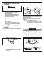
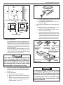
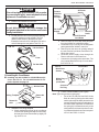
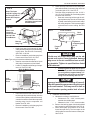
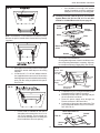
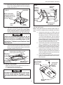
Place grill on return air cover and snap in place.
Decal is on end over circuit board.
7. Place slide handle through slots in grill into the
slide posts. Handle will fit in either direction.
8. This completes the installation of the air conditioner.
We recommend that power be supplied to the air
conditioner and check for proper operation. See
section "J. Configuration Of Remote" and refer to
Operating Manual or User's Guide for a description
of the air conditioner operation.
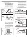
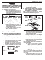
BATTERY COMPARTMENT
FIG. 33
J1 J2 J3 J4
OFF
Dip Switches
"ON"
Dip Switches
"OFF"
J. CONFIGURATION OF REMOTE
The Hand Held Remote when shipped from Dometic is always programmed as a cool/furnace model. The dip switches
are located in the hand held remote battery compartment.
See FIG. 33. If the control is to be used with the electric
heat strip or without the furnace its configuration must be
changed as follows:
1. Cool/furnace operation: Dip switches 1,2,& 3 "ON"
- dip switch 4 "OFF".
2. Cool Only-no heat operation: Dip switch 1 & 3 "ON"
- dip switches 2 & 4 "OFF".
3. Cool/Heat operation: Dip switches 1,2,3, & 4 "ON"
-no dip switches "OFF".
Note: After the remote switches are changed, point remote
at the receiver and press the reset button.
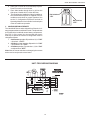
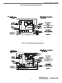
UNIT FIELD WIRING DIAGRAM
COMPRESSOR
PASSED
DIELECTRIC
C
MOTOR
R
GRN/YEL
S
O.L.
*
6 PIN CONN
BLU
WHT
BRN
WHT
FAN
C
HERM
1
BLK
2
YEL
3
RED
4
WHT
5
RED
WHT
RUN CAP
RED
6
COMP STARTER
START
CAP
PTCR
GRN/YEL
*
*
NOT USED ON
SOME MODELS
3105052.033
16