1
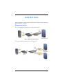
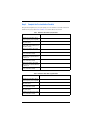
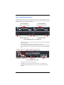
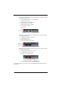
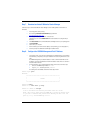
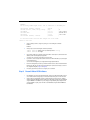
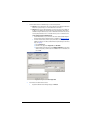
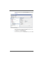
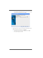
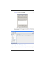
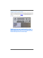
QUICK START GUIDE
[ Quick Start Guide ]
INTELLIGENT STORAGE ROUTER INSTALLATION
iSR6200
z
Purchasers of OEM products should consult with the OEM for support.
Please feel free to contact your QLogic approved reseller or QLogic Technical Support at
any phase of integration for assistance. QLogic Technical Support can be reached by the
following methods:
Web
http://support.qlogic.com
E-mail
[email protected]
The QLogic knowledge database contains troubleshooting information for the QLogic
adapters. Access the database from the QLogic Support Web page,
http://support.qlogic.com. Use the Support Center search engine to look for specific
troubleshooting information.
Quick Start Guide
The QLogic® iSR6200 Series of intelligent Storage Router (iSR) provides servers with iSCSI connectivity to SAN-attached
Fibre Channel based disk or tape storage.
Suggested Configurations
Figure 1 shows the iSR6200 connecting iSCSI servers to a direct-attached storage array.
Fibre
Channel
iSCSI
iSCSI
iSCSI
Initiator
iSR6200
IP Switched
Network
Server
RAID-Based Fibre
Channel Storage System
Figure 1. iSR6200 in Direct Attach Configuration
Figure 2 shows the iSR6200 connecting iSCSI servers to a SAN-attached array.
Fibre
Channel
iSCSI
iSCSI
Initiator
Server
iSCSI
IP Switched
Network
iSR6200
Fibre
Channel
Fibre Channel
SAN
RAID-Based
Fibre Channel
Storage Systems
Fibre Channel
SAN
Figure 2. iSR6200 in SAN-Attach Configuration
3
Installation Instructions
This quick start guide provides procedures for installing and configuring your new QLogic iSR6200 router.
■
Step 1. Verify the package contents.
■
Step 2. Complete the pre-installation checklist.
■
Step 3. Mount the router.
■
Step 4. As needed, insert additional blade into router.
■
Step 5. Install the small form factor pluggable (SFP) transceivers.
■
Step 6. Apply power to the router.
■
Step 7. Download and install SANsurfer® Router Manager
■
Step 8. Configure the iSR6200 management port IP address.
■
Step 9. Present LUNs to iSCSI initiators.
■
Step 10. Configure second blade (if provided).
■
Step 11. Configure an FCIP route
■
Step 12. Locate the blade serial number for the license key activation.
Step 1. Verify the Package Contents
Verify the contents of the purchased production package, either C12 or B10.
The iSR6200 router production package (C12) includes the following hardware components:
■
iSR6200 router chassis with two blades installed
■
DB9 to RJ45 cable adapter
■
Power cable (6 foot black)
■
Rail Mounting Kit, part number 50990-00
■
WEEE Conformance card
■
Read Me First card
■
China RoHs Electronic Info, RoHs Switch/Power/Fan SKUs Toxic Substance (Chinese Vers) 20 Years
■
iSR6200 Quick Start Guide (this document)
The standalone blade production package (B10) includes the following hardware components:
4
■
One blade
■
SFPs
■
WEEE Conformance card
■
Read Me First card
■
China RoHs Electronic Info, RoHs Switch/Power/Fan SKUs Toxic Substance (Chinese Vers) 20 Years
■
iSR6200 Quick Start Guide (this document)
Step 2. Complete the Pre-Installation Checklist
During the initial configuration process, the system prompts you to enter information for each blade contained in the
iSR6200. Use the spaces provided in Table 1 and Table 2 to record the IP addresses for each blade.
Table 1. Worksheet for Router Blade 1 (left) Parameters
Symbolic name of the iSR6200 Blade 1
Management port IP address, subnet
mask, and gateway (if not using DHCP)
iSCSI port 1 IP address, subnet mask,
and gateway (GE-1)
IP address of the Internet simple name
service (iSNS) server for iSCSI port 1 (if
iSNS will be enabled)
iSCSI port 2 IP address, subnet mask,
and gateway (GE-2)
IP address of the iSNS server for iSCSI
port 2 (if iSNS will be enabled)
iSCSI port 3 IP address, subnet mask,
and gateway for the optional (FC3, GE-3,
or 10GE-3) port
IP address of the iSNS server for iSCSI
port 3 (if iSNS will be enabled)
iSCSI port 4 IP address, subnet mask,
and gateway for the optional (FC4, GE-4,
or 10GE-4) port
IP address of the iSNS server for iSCSI
port 4 (if iSNS will be enabled)
Table 2. Worksheet for Router Blade 2 (right) Parameters
Symbolic name of the iSR6200 Blade 2
Management port IP address, subnet
mask, and gateway (if not using DHCP)
iSCSI port 1 IP address, subnet mask,
and gateway (GE-1)
IP address of the iSNS server for iSCSI
port 1 (if iSNS will be enabled)
iSCSI port 2 IP address, subnet mask,
and gateway (GE-2)
IP address of the iSNS server for iSCSI
port 2 (if iSNS will be enabled)
5
Table 2. Worksheet for Router Blade 2 (right) Parameters (Continued)
iSCSI port 3 IP address, subnet mask,
and gateway for the optional (FC3, GE-3,
or 10GE-3) port
IP address of the iSNS server for iSCSI
port 3 (if iSNS will be enabled)
iSCSI port 4 IP address, subnet mask,
and gateway for the optional (FC4, GE-4,
or 10GE-4) port
IP address of the iSNS server for iSCSI
port 4 (if iSNS will be enabled)
Step 3. Mount the Router
To mount the iSR6200 router in the rack, follow the instructions (QLogic 6200 Storage Router Rack Mounting Guide)
provided in the rack mount kit.
Step 4. Insert Additional Blade into Router (as needed)
If you have purchased an additional blade (B10), insert it into the iSR6200 router as follows:
1.
Move the ejector latch handle to a position horizontal to the base.
2.
Slide the blade into an open chassis slot.
3.
When the blade is completely inserted, raise the ejector latch handle to snap the blade into place.
Step 5. Install the SFP Transceivers
An SFP transceiver is required for each router port that will be connected to a Fibre Channel device or switch. SFPs are
included in the package. If you prefer to use SFP transceivers other than the ones provided, purchase one of the QLogic
recommended transceivers listed in Table 3.
Table 3. Recommended Replacement Transceivers
8Gb Transceivers
Manufacturer
Finisar®
®
JDS Uniphase
Part Number
10Gb Transceivers
Manufacturer
Part Number
FTLF8528P2BCV-QL
Finisar
FTLX8571D3BCL
PLRXPL-VC-SH4-22-N-Q
PLRXPL-VC-SH4-23-N-QL
JDS Uniphase
PLRXPL-SC-S43-22-N
To install an SFP transceiver, insert the transceiver into the router port, and then press gently until it snaps in place. The
transceiver will fit only one way. If the transceiver does not install under gentle pressure, flip it over and try again.
6
Step 6. Apply Power to the Router
The iSR6200 router chassis contains one or two router blades, along with a power cooling module (PCM) for each blade.
Each chassis blade provides light emitting diodes (LEDs) and connectors that face the front of the chassis. Each PCM
provides a power connector, as well as an LED (see Figure 3).
Front Plate iSR6200 Blade 1
Front Plate iSR6200 Blade 2
Blade Option Ports Based on Model
Blade Option Ports Based on Model
10GbE2
10GbE1
iSR6250
10GbE2
10GbE1
iSR6250
Intelligent Storage Router
FC1
MGMT
Intelligent Storage Router
FC2
FC1
IOIOI
MGMT
PCM Status LED
Power Connector
FC2
IOIOI
PCM Status LED
Back Plate PCM for Blade 2
Power Connector
Back Plate PCM for Blade 1
Figure 3. iSR6200 Router Chassis—Front and Back Plates
1.
Attach the AC power cord to the power connector, located on the back of the PCM connected directly
behind the router blade.
2.
Connect the opposite end of the power cord to the wall outlet or power strip.
3.
Check the PCM power LED to make sure the PCM is operational (green = power, yellow = no AC power).
Figure 4 shows the location of the ports and LEDs on one of the blades contained within the iSR6200
unit.
RS232 Port
Heartbeat LED
Power LED
Blade Option Ports Based on Model
GE4
10GbE2
GE3
10GbE1
iSR6240
iSR6250
Intelligent Storage Router
Intelligent Storage Router
iSR6200 System
MGMT
IOIOI
Management Port
FC1
System Fault LED
FC2
Fibre Channel Ports
GE1
GE2
iSCSI Ports
Figure 4. iSR6200 Blade Ports and LEDs
4.
Verify that the router’s input power LED is illuminated.
The iSR6200 router runs its self test and begins normal operation—this may take a minute.
5.
Verify that the heartbeat LED is blinking (once per second), and that the system fault LED is not
illuminated.
7
The iSR6240 router blade (see Figure 5) adds two iSCSI Ethernet ports to the blade configuration.
Each port has the following capacity:
❑
Auto negotiating transmission rates of 100 and 1000Mbps
❑
Full duplex transmission mode
❑
Support for jumbo frames (at 1000Mbps only)
❑
RJ45 copper Ethernet connector type
❑
iSCSI header and data digest in the hardware
❑
IPv4 and IPv6 protocol support
❑
iSCSI offload
Activity
Link Status
Figure 5. iSCSI (GE) Ports on the iSR6240 Router Blade
The iSR6250 router blade (see Figure 6) adds two 10Gb Ethernet ports to the blade configuration.
Each port has the following capacity:
❑
10GbE iSCSI ports that run in full duplex mode
❑
Support for jumbo frames
❑
IPv4 and IPv6 protocol support
❑
iSCSI header and data digest in the software
SAN (Green)
LAN (Green)
Figure 6. 10Gb Ethernet Ports on the iSR6250 Router Blade
The iSR6260 router blade (see Figure 7) adds two more Fibre Channel ports to the blade configuration.
Each port has the following capacity:
❑
Auto-negotiating transmission rates of 2, 4, or 8Gb
❑
Hot-pluggable SFP Fibre Channel connector
❑
N_Port, NL_Port, or transparent port type
8Gb (Yellow)
4Gb (Green)
2Gb (Amber)
Figure 7. Fibre Channel Ports on the iSR6260 Router Blade
For installation details, diagnostics, and troubleshooting, see the iSR6200 QLogic intelligent Storage Router (iSR)
Installation Guide.
8
Step 7. Download and Install SANsurfer Router Manager
Follow these steps to download the SANsurfer Router Manager tool from the QLogic Web site and install it on a
workstation:
1.
2.
Close all programs currently running.
Go to the QLogic Downloads and Documentation page located here:
http://driverdownloads.qlogic.com/
3.
Under QLogic Products, type iSR6200 in the search box.
(Alternatively, you can click the Guided Search link to obtain assistance in locating the utility to
download.)
4.
In the Resource Name column, click the SANsurfer Router Manager version for your operating system.
5.
Click Download Now.
6.
Save the file to your computer.
7.
Run the installer. (If your Internet browser displays a security warning, you can safely bypass it.)
8.
Follow the prompts in the SANsurfer Router Manager installation wizard.
Step 8. Configure the iSR6200 Management Port IP Address
1.
Using a switch or hub, connect the router’s management port (10/100 Ethernet) to your workstation.
As an alternative, you may directly connect your workstation to the router using an Ethernet crossover
cable.
The iSR6200 management port’s default IP address is 10.0.0.1, subnet 255.0.0.0. Make sure the
workstation connected to the iSR6200 router has Ethernet address 10.0.0.x, where x is other than 1
and subnet mask is 255.0.0.0.
2.
From the workstation, open a command window and using a Telnet session, follow these steps:
a.
Connect to the iSR6200 using IP address 10.0.0.1.
b.
Log in as guest, and use the password password.
The following shows the iSR6200 command line interface (CLI) window.
iSR6200 login: guest
Password:
******************************************************
*
*
*
ISR6200
*
*
*
******************************************************
iSR6200 #> blade 1
iSR6200 <1> #> admin start -p config
iSR6200 <1> (admin) #> set mgmt
A list of attributes with formatting and current values will follow.
Enter a new value or simply press the ENTER key to accept the current value.
If you wish to terminate this process before reaching the end of the list
press 'q' or 'Q' and the ENTER key to do so.
9
WARNING:
The following command might cause a loss of connections to the MGMT port.
IPv4
IPv4
IPv4
IPv4
IPv4
IPv6
Interface (0=Enable, 1=Disable)
Mode (0=Static, 1=DHCP, 2=Bootp, 3=Rarp)
Address
Subnet Mask
Gateway
Interface (0=Enable, 1=Disable)
[Enabled
[Dhcp
[10.0.0.1
[255.0.0.0
[0.0.0.0
[Disabled
]
]
]
]
]
]
0
172.17.136.55
255.255.254.0
172.17.136.1
All attribute values that have been changed will now be saved.
Connect to host lost.
3.
Select the blade you want to configure by issuing one of the following CLI commands:
blade 1
blade 2
4.
At the prompt, issue the following CLI commands (for blade 2):
iSR6200 (admin)#> admin start (the default password is config)
iSR6200 (admin)#> set mgmt
5.
Specify the mode. QLogic recommends using a static address. Select option 0, and then enter the IP
address, subnet mask, and gateway, if applicable.
You will lose the connectivity of the Telnet session at this time.
6.
If you want to continue using the CLI, restart the Telnet session with the IP address you just assigned
to the management port.
You now have the management port configured with the appropriate IP address.
7.
Connect the management port cable to your Ethernet network. Connect cables to the iSCSI and Fibre
Channel ports (GE1, FC1, and FC2, as well as the blade option ports based on model), as shown in
the configuration diagrams (Figure 1 and Figure 2).
8.
If necessary, repeat these procedures to configure your second blade.
Step 9. Present LUNs to iSCSI Initiators
10
1.
If the iSR6200 is connected in the Fibre Channel fabric, make sure the Fibre Channel fabric zoning is
set so that Fibre Channel storage array ports and router Fibre Channel ports are in the same zone.
2.
Using storage array management software, create all LUNs that you want to present to all iSCSI
initiators through this iSR6200. Present the LUNs from the Fibre Channel storage array to the iSR6200
using the WWPNs of this iSR6200. If you are setting up a high availability (HA) configuration that
uses two iSR6200s as a pair, present the LUNs to both iSR6200s using Fibre Channel WWPNs of
both iSR6200s.
3.
Create the iSCSI initiator list in iSR6200 using one of the following methods:
❑
Method 1: Enter the iSCSI initiator name using the SANsurfer Router Manager’s Add Initiator
Wizard. The system prompts you to enter the iSCSI name of an initiator.
❑
Method 2: From the server with iSCSI initiators, run a discovery session for the iSCSI port
IP address of the iSR6200. This automatically registers the iSCSI initiator names with the
iSR6200. Running the iSCSI discovery session on different OS environments may vary. The
following example illustrates how to run an iSCSI discovery session on a Windows Server.
To run a discovery session on Windows Server:
a. Install an iSCSI initiator on your server. This can be either a dedicated iSCSI adapter or
an iSCSI software initiator for Windows like the one available from www.microsoft.com.
b. Invoke the software initiator, and then specify the IP address of the iSCSI port on your
iSR6200. For example, on the Microsoft iSCSI Initiator Properties dialog box, follow these
steps (see Figure 8):
(1) Click the Discovery tab.
(2) On the Discovery page under Target portals, click Add Portal.
(3) On the Add Target Portal dialog box, in the IP address or DNS name box, type the IP
address of the portal you want to add, leave the Port number set to the default, and
then click OK.
Figure 8. Adding the iSCSI Initiator Target Portal
4.
Present LUNs to the iSCSI initiator as follows:
a.
To update the SANsurfer Router Manager display, click Refresh.
11
The iSCSI initiator name appears under the Discovered iSCSI Initiators node in the router tree
in the left pane, and details for the initiator appear on the Information page in the right pane
(see Figure 9).
Figure 9. Discovered iSCSI Initiators Information
To assign a LUN to a server, run the Target Presentation/LUN Mapping Wizard. This wizard
allows you to map a LUN to the iSCSI initiator on your server.
12
b.
On the Wizards menu, click LUN Presentation Wizard.
c.
On the LUN Presentation Type window, click LUN Presentation as the type, and then click Next.
d.
On the Select the Initiators for LUN Presentation window (Figure 10), select one or more
initiators, and then click Next.
Figure 10. Target Presentation/LUN Mapping Wizard: Selecting Initiators
e.
On the LUN Selection window, select one or more LUNs under the virtual port group node, and
then click Next.
f.
On the Confirm Changes window, review the LUN presentation information, and then click Next.
g.
In the Security Check dialog box, type the admin password, and then click OK to continue.
13
h.
On the LUN Masking Configuration Status window (Figure 11), review the results of the target
ports presented for the selected initiators, and then click Finish.
Figure 11. Target Presentation/LUN Mapping Wizard: Viewing Status
5.
14
Log into the iSCSI initiator. For example, if you are using the Microsoft iSCSI initiator, follow these
steps:
a.
On the iSCSI Initiator Properties dialog box, click the Targets tab.
b.
On the Targets page, select the target (the status is Inactive), and then click Log On.
c.
On the Log On To Target dialog box, click OK.
After the iSCSI initiator logs into the newly presented LUN, the iSCSI Initiator Properties Targets page
(see Figure 12) shows the target status as Connected.
Figure 12. iSCSI Initiator Properties: Target Connected
Now, when you select your iSCSI initiator in the left pane of the SANsurfer Router Manager window,
the Information page shows the status as Logged In. The LUN List page (Figure 13) shows the LUNs
mapped to that initiator.
Figure 13. LUN List Page
Step 10. Configure Second Blade (if provided)
To configure a second blade (if provided), repeat Step 9. Use Table 2 on page 5 to build the blade option configuration.
15
Step 11. Configure an FCIP Route
Fibre Channel over IP (FCIP)—a licensed feature of the iSR6200—is a protocol used to transport Fibre Channel frames
over TCP/IP to provide SAN-over-WAN capabilities. FCIP is commonly used to interconnect (merge) SANs that are
separated by such a distance that a direct connection is cost-prohibitive or technically unfeasible.
For detailed information about configuring FCIP parameters, refer to the iSR6200 QLogic intelligent Storage Router (iSR)
Installation Guide, chapter 5.
The iSR6200 system FCIP implementation has the following attributes and capabilities:
■
Compatible with all Fibre Channel vendor fabrics (all Fibre Channel switches)
■
E_Port extension—Bridges same Fibre Channel vendor SANs (such as Fibre Channel switches)
■
F_Port extension—Does not merge fabrics
■
Supported configurations:
■
❑
Two same-vendor Fibre Channel SAN islands
❑
Direct connect from one N_Port to a remote SAN island
Support for 1GbE and 10GbE connections (a licensed feature):
❑
100MBps on each 1Gb Ethernet or 8Gb Fibre Channel route
❑
400MBps on each 10Gb Ethernet or 8Gb Fibre Channel route
■
Compression at 1.5Gbps
■
TCP/IP selective acknowledgement (SACK) of packets
■
Support for bandwidth throttling
■
Distances up to 250ms with TCP window size up to 16M
■
Trace route and ping support links up to two locations per blade, four locations per chassis (two blades)
■
FICON® support
Step 12. Locate the Blade Serial Number for License Key Activation
The serial number of each blade is required for activating the router license key on the License Key Activation form. You
can locate the blade serial number (SN) with the following methods:
■
Use the QLogic utilities, either the CLI or SANsurfer Router Manager (GUI). (Recommended method; most
reliable)
■
View the serial number marked on the bottom of blade.
Serial Number Formats
It is very important that you enter the blade’s exact and entire serial number (case-sensitive). If any part of the serial
number is different or truncated, the generated license key will not work. The QLogic iSR6200 products have 10-digit
alphanumeric serial numbers, for example:
SN: 0951F00579
16
Using the CLI to Locate the Serial Number
To find the serial number of your blade from the command line, follow these steps:
1.
Telnet into the iSR6200, and then start the CLI.
2.
Log in as guest; the default password is password.
3.
Issue the show chassis command.
4.
Under Blade x Information, locate and write down the serial number for each blade.
In the following example, the two blade serial numbers are shown in bold blue text:
iSR6200 login: guest
Password:
******************************************************
*
*
*
ISR6200
*
*
*
******************************************************
iSR6200 #> show chassis
Chassis Information
--------------------Product Name
Chassis Name
Serial Number
HW Version
Fan Speed
iSR6200
0951F00579
31896-02 B
Normal
Blade 1 Information (Left Slot)
------------------------------Status
Online
Product Name
iSR6200
Symbolic Name
Blade-1
Serial Number
0952F00032
HW Version
31895-03 A
SW Version
3.1.0.2
Temp (Front/Rear/CPU1/CPU2)
40C/28C/35C/33C
Power Cooling Module 1
---------------------Status
Power Source
Fan1/Fan2/Fan3
Installed
Connected
Healthy/Healthy/Healthy
Blade 2 Information (Right Slot)
-------------------------------Status
Online
Product Name
iSR6200
Symbolic Name
Blade-2
Serial Number
0952F00019
17
HW Version
SW Version
Temp (Front/Rear/CPU1/CPU2)
Power Cooling Module 2
---------------------Status
Power Source
Fan1/Fan2/Fan3
iSR6200 #>
31895-03 A
3.2.0.0rc6b2
35C/25C/31C/33C
Installed
Not Connected
Healthy/Healthy/Healthy
Using the GUI to Locate the Serial Number
The following shows how to locate the serial number using the SANsurfer Router Manager utility provided by QLogic.
Refer to the iSR6200 Router Manager User’s Guide for specific information regarding the management utility.
To find the serial number of your blade from SANsurfer Router Manager, follow these steps:
1.
In the SANsurfer Router Manager’s left pane, click the Router tab.
2.
In the left pane’s router tree, click Blade 1.
3.
In the right pane on the Information page, locate and write down the Serial Number shown under
Basic Information (see Figure 14).
4.
Repeat the preceding steps to determine the Blade 2 serial number.
Figure 14. Locating the Blade Serial Number in the GUI
18
Finding the Serial Number on the Physical Blade
The iSR6200 products have the serial number printed on the bottom of the blade. For a detailed procedure for removing
the blade, refer to the iSR6200 QLogic intelligent Storage Router (iSR) Installation Guide, “Removal and Replacement”
chapter. You can view the installation guide online at QLogic.com on the Downloads and Documentation page for your
model number.
Figure 15 shows the labeling on a QLogic iSR6200 Series blade.
Figure 15. Locating the Blade Serial Number on the Physical Blade
Congratulations! You have now successfully installed your QLogic
iSR6200, mapped target LUNs to an iSCSI initiator on your server, and
determined the blade serial number. Your server should see the Fibre
Channel LUNs through the server’s volume manager.
19
20
21
22
© 2009–2012 QLogic Corporation. QLogic, the QLogic logo, SANsurfer, and SmartWrite are trademarks or registered
trademarks of QLogic Corporation. FICON is a registered trademark of International Business Machines
Corporation.Finisar is a registered trademark of Finisar Corporation. JDSU is a trademark of JDS Uniphase Corporation.
All other brands and product names are trademarks or registered trademarks of their respective owners. Information
supplied by QLogic is believed to be accurate and reliable. QLogic Corporation assumes no responsibility for any errors
in this brochure. QLogic Corporation reserves the right, without notice, to make changes in product design or
specifications.
Corporate Headquarters
QLogic Corporation
26650 Aliso Viejo Parkway
Aliso Viejo, CA 92656
949.389.6000 www.qlogic.com
*IS0054504-00
IS0054504-00 G
International Offices
UK | Ireland | Germany | France
India | Japan | China
Hong Kong | Singapore | Taiwan
G*