1
Important: On FAC, FEC, VMA16, and IOM Series controllers only, the 128 DIP switch on the controller’s device
address DIP switch block is a mode switch used to enable the controller to operate in a wireless mode
using the ZFR1800 Series Wireless Field Bus System. On any FAC, FEC, VMA16, or IOM Series
controller that is hardwired to an MS/TP Bus, set the 128 DIP switch to the OFF position. Operating
any FAC, FEC, VMA16, or IOM that is hardwired to an MS/TP Bus with the controller’s 128 DIP switch
set to the ON position results in communication failure on the bus.
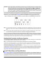
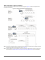
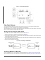
As you set the device address, the best practice is to set the highest switch value first, then the next highest switch
value, and so on, until the total of the switch values equal the intended device address. For example, positioning
switches 16, 4, and 1 to ON (as shown in Figure 8) sets the device address to 21 for a device on the FC bus.
Figure 8: Setting the Device Address and Wireless Operation Mode on the ADDRESS DIP Switch Block
Note: You must set switch 128 to OFF on all Metasys controllers that are hardwired to an FC Bus. Set switch 128
to ON only on FACs, FECs, VMA16s, and IOMs that operate on a Metasys ZFR1800 Series Wireless Field
Bus.
Note: Devices may go offline momentarily when a device address is changed on an active bus. A device reset is
not required on field controllers or supervisory engines after changing the MS/TP address.
Some devices, such as the TEC26xx Series thermostats and third-party MS/TP devices, use their own configuration
settings to establish the device address for their connection to the bus. Refer to the device manufacturer’s product
documentation for instructions on setting the device address. The device address values for TEC26xx thermostats
and all third-party devices must comply with the rules and ranges described previously.
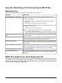
Enabling Field Controllers for Wireless Operation
The ZFR1800 Series Wireless Field Bus System enables wireless communication, allowing you to create wireless
connections between NAEs or NCEs and FACs, FECs, or VMA16s.
Note: The ZFR1800 Series Wireless Field Bus System is not supported on the Remote Field Bus.
On FAC, FEC, and VMA16 controllers, you can enable the controller to operate with a ZFR1800 Series wireless
system and connect an MS/TP Bus in a wireless mode by setting the 128 DIP switch on the device address DIP
switch block to ON. See Figure 8 for more information.
To operate with a ZFR1800 Series field bus, an FAC, FEC, or VMA16 must be connected to a ZFR1811 Wireless
Field Bus Router, and the associated NAE or NCE must be connected to a ZFR1810 Wireless Field Bus Coordinator.
See Related Documentation for references to more information about the ZFR1800 Series Wireless Field Bus
System, FACs, FECs, VMA16s, NCEs, and NAEs.
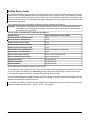
Local FC Bus Rules and Specifications
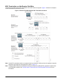
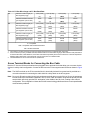
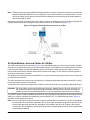
Table 5, Table 6, and Figure 9 provide rules and specifications for the local FC bus. (For the Remote Field Bus, see
Table 10.) Metasys MS/TP devices generate less data traffic than third-party MS/TP devices and TEC26xx thermostats.
Connecting third-party devices or TEC26xx thermostats to the FC bus increases data traffic, reduces bus performance,
and reduces the number of devices that can be connected to the FC bus.
MS/TP Communications Bus Technical Bulletin
21