1
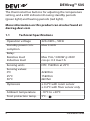
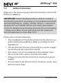
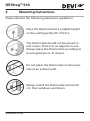
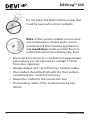
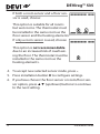
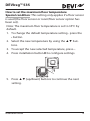
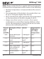
Installation Guide
DEVIreg™ 535
Electronic Thermostat
www.DEVI.com
The English language is used for the original instructions.
Other languages are a translation of the original instructions.
(Directive 2006/42/EC)
DEVIreg™ 535
Table of Contents
1
Introduction . . . . . . . . . . . . . . .
1.1
Technical Specifications . . . . .
1.2
Safety Instructions . . . . . . . .
3
4
6
2
Mounting Instructions
7
3
Settings
. . . . . . . . . . . . . . . . .
11
4
Warranty
. . . . . . . . . . . . . . . . .
15
5
Disposal Instruction
1
Introduction
. . . . . . . . .
. . . . . . . . . .
16
DEVIreg™ 535 is an electronic timer temperature controller,
specially designed for floor heating systems. The thermostat is provided with a room sensor to control the room
temperature and an additional floor sensor to limit the
maximum floor temperature. The thermostat can be either
flush-mounted or surface-mounted.
Once set, the thermostat will automatically adjust the heat
to meet your comfort requirements by measuring the floor
temperature and combining it with the measured air temperature regardless of changing weather conditions.
Installation Guide
3
DEVIreg™ 535
The thermostat has buttons for adjusting the temperature
setting, and a LED indicator showing standby periods
(green light) and heating periods (red light).
More information on this product can also be found at:
devireg.devi.com
1.1
4
Technical Specifications
Operation voltage
220-240V~, 50Hz
Standby power consumption
Max 0.30W
Relay:
Resistive load
Inductive load
Max 15A / 3450W @ 230V
cos φ= 0.3 max 1A
Sensing units
NTC 15kOhm at 25°C
Sensing values:
0°C
25°C
50°C
42kOhm
15kOhm
6kOhm
Hysteresis
± 0.2°C with room sensor
± 0.4°C with floor sensor only
Ambient temperature
-10°C to +30°C
Frost protection temp.
5°C -
Installation Guide
DEVIreg™ 535
Temperature range
5-35°C with room sensor
5-45°C with floor sensor only
Floor max 20-50°C
Floor min 10-35°C, when installed with combination of room
and floor sensor
Cable specification max
1x4mm2 or 2x2,5mm2
Ball pressure temperature
75°C
Pollution degree
2 (domestic use)
Type
1C
Storage temperature
-20°C to +65°C
IP class
31
Protection class
Class II -
Dimensions
85 x 85 x 54mm (in-wall depth:
24mm)
Weight
107g
The product complies with the EN/IEC Standard "Automatic
electrical controls for household and similar use":
▪ EN/IEC 60730-1 (general)
▪ EN/IEC 60730-2-7 (timer)
▪ EN/IEC 60730-2-9 (thermostat)
Installation Guide
5
DEVIreg™ 535
1.2
Safety Instructions
Make sure the mains supply to the thermostat is turned off
before installation.
IMPORTANT: When the thermostat is used to control a
floor heating element according to "Household and similar
electrical appliances - Safety - EN/IEC 60335-1 : General requirements" and "EN/IEC 60335-2-96: Particular requirements for flexible sheet heating elements for room heating
", always use a floor sensor and never set the maximum
floor temperature to more than 35°C.
Please also note the following:
▪ The installation of the thermostat must be done by an
authorized and qualified installer according to local
regulations.
▪ The thermostat must be connected to a power supply
via an all-pole disconnection switch.
▪ The sensor is to be considered as live voltage. Have
this in mind if the sensor must be extended.
▪ Always connect the thermostat to continuous power
supply.
▪ Do not expose the thermostat to moisture, water, dust,
and excessive heat.
6
Installation Guide
DEVIreg™ 535
2
Mounting Instructions
Please observe the following placement guidelines:
Place the thermostat at a suitable height
on the wall (typically 80-170cm.).
The thermostat should not be placed in
wet rooms. Place it in an adjacent room.
Always place the thermostat according to
local regulation on IP classes.
Do not place the thermostat on the inner
side of an exterior wall.
Always install the thermostat at least 50
cm. from windows and doors.
Installation Guide
7
DEVIreg™ 535
Do not place the thermostat in a way that
it will be exposed to direct sunlight.
Note: A floor sensor enables a more accurate temperature control and is recommended in all floor heating applications
and mandatory under wooden floors to
reduce the risk of over-heating the floor.
▪ Place the floor sensor in a conduit in an appropriate
place where it is not exposed to sunlight or draft
from door openings.
▪ Equally distant and >2cm from two heating cables.
▪ The conduit should be flush with the floor surface countersink the conduit if necessary.
▪ Route the conduit to the connection box.
▪ The bending radius of the conduit must be min
50mm.
8
Installation Guide
DEVIreg™ 535
Follow the steps below to mount the thermostat:
1. Open the thermostat:
devireg™550
D
▪ Gently press the release tab in the bottom of the
thermostat using a flat object.
▪ Carefully pull off the front cover.
2. Connect the thermostat according to the connection
diagram.
N
LOAD
L
L
LOAD
Mains
Max. Load
220-240V~ 15 (1) A
NTC
Sensor
N
IP31
-10T30
D535
Installation Guide
Standby maximum 0.3W
9
DEVIreg™ 535
The screen of the heating cable must be connected to
the earth conductor of the power supply cable by using a separate connector.
Note: Always install the floor sensor in a conduit in the
floor.
3. Mount and reassemble the thermostat.
▪ Fasten the thermostat to a socket or an exterior wall
box by driving the screws through the holes in each
side of the thermostat.
▪ Tighten the screws to fasten the thermostat.
4. Turn on the power supply.
Initially main supply the thermostat for 15 hours to fully
charge the battery. The current time and day is then kept
for 80 days if mains supply is off. All other settings are stored permanently.
10
Installation Guide
DEVIreg™ 535
3
Settings
Sensor: How to specify whether an external floor sensor, the built-in room sensor or both is used to control
the floor heating
Note: The floor sensor option is selected by default.
1. Press the installation button D with a blade end.
devireg™550
D
2. Press the • button.
3. Select one of the following options using the ▲▼
buttons:
If only a floor sensor is used, choose:
The built-in room sensor is not used.
This option is suitable for rooms in
which a constant floor temperature is
required, e.g. in a bathroom.
Installation Guide
11
DEVIreg™ 535
If both a room sensor and a floor sensor is used, choose:
This option is suitable for all rooms
but wet rooms. The thermostat must
be installed in the same room as the
floor sensor and the heating elements.
If only a room sensor is used, choose:
This option is not recommendable
due to an increased risk of overheating the floor. The thermostat must be
installed in the same room as the
heating elements.
4. To accept new selected sensor mode, press •.
5. Press installation button D to configure settings.
6. If you have chosen the floor sensor or room/floor sensor option, press ▲▼ (up/down) buttons to continue
to the next setting.
12
Installation Guide
DEVIreg™ 535
How to set the maximum floor temperature
Special condition: This setting only applies if a floor sensor
is used (the floor sensor or room/floor sensor option has
been set).
Note: The maximum floor temperature is set to 35°C by
default.
1. To change the default temperature setting - press the
• button.
2. Select the new temperature by using the ▲▼ buttons.
3. To accept the new selected temperature, press •.
4. Press installation button D to configure settings.
devireg™550
D
5. Press ▲▼ (up/down) buttons to continue the next
setting.
Installation Guide
13
DEVIreg™ 535
Note: Please contact the floor supplier before changing the
maximum floor temperature and be aware of the following:
▪ The floor temperature is measured where the sensor is
placed.
▪ The temperature of the bottom of a wooden floor can
be up to 10 degrees higher than the top.
▪ Floor manufactures often specify the max temperature
on the top surface of the floor (usually 27-28˚C).
▪ Always use a floor sensor or a room + floor sensor
combination to control floor heating. Without a floor
sensor, the temperature control may be less accurate
and you risk overheating the floor.
Thermal Examples of floor- Details
resisting
ance
[m2K/W]
0.05
8 mm HDF based
laminate
> 800 kg/m3
28˚C
0.10
14 mm beech parquet
650 - 800
kg/m3
31˚C
0.13
22 mm solid oak
plank
> 800 kg/m3
32˚C
< 0.17
Max. carpet thickness suitable for
floor heating
acc. to EN
1307
34˚C
22 mm solid fir
planks
450 - 650
kg/m3
35°C
0.18
14
Approximate
setting for
25˚C floor
temperature
Installation Guide
DEVIreg™ 535
How to define the temperature scale
Special condition: If floor sensor is selected, the numerical
scale with steps from 1 - 6 must be selected.
Note: By default, the Celsius scale is used.
1. To change the default temperature scale, press the •
button.
2. Select a scale, use the ▲▼ buttons.
You can choose between a numerical scale with steps
from 1- 6 or the Celsius scale with steps from 5° - 45°.
3. To accept the selected temperature scale, press •.
4. If desired, go back or forward through your installation settings by pressing the ▲▼ (up/down) buttons.
5. Press installation button D to exit the installation
mode.
6. Put the frame and front back on.
4
Warranty
2
YEAR
Installation Guide
15
DEVIreg™ 535
5
16
Disposal Instruction
Installation Guide
DEVIreg™ 535
Installation Guide
17
DEVIreg™ 535
18
Installation Guide
DEVIreg™ 535
Danfoss A/S
Electric Heating Systems
Ulvehavevej 61
7100 Vejle
Denmark
Phone: +45 7488 8500
Fax: +45 7488 8501
E-mail: [email protected]
www.DEVI.com
Danfoss can accept no responsibility for possible errors in catalogues, brochures and other printed material. Danfoss reserves the right to alter its
products without notice. This also applies to products already on order provided that such alterations can be made without subsequential changes
being necessary in specifications already agreed. All trademarks in this material are property of the respective companies. DEVI and the DEVI logotype are trademarks of Danfoss A/S. All rights reserved.
08091234 & VICKI402
Produced by Danfoss © 03/2012
Timer Thermostat
Floor/Room Sensor
220-240V~
50-60Hz~
+5 to +45°C
15A/3450W@230V~
IP 31
140F1050
DEVIREG 535 ELKO
5 703466 209134
Designed in Denmark for Danfoss A/S
NO EL 5402665
FI SSTL 3531009
Product Documentation