1
BM 2609140574 08-08
9/3/08
8:40 AM
Page 3
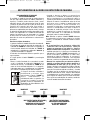
Safety Rules for Multi-Detector
Read all instructions. Failure to follow all instructions listed below may
! WARNING result in electric shock, fire and/or serious injury.
SAVE THESE INSTRUCTIONS
The detector alone should
The multi-detector’s ability to detect objects
is affected by the proximity of other equipment
that produce strong magnetic or
electromagnetic fields, and by moisture,
metallic building materials, foil-laminated
insulation materials and/or conductive
wallpaper.
! WARNING not be relied on exclusively
to locate items below the scanned surface.
Use other information sources to help locate
items before penetrating the surface. Such
additional sources include construction plans,
visible points of entry of pipes and wiring into
walls, such as in a basement, and standard
16” and 24” stud spacing practices.
The multi-detector’s ability to detect wood
substructures (studs) is also affected by
inconsistency on the thickness of the surface
material, such as plaster and lath.
Before
penetrating
a
! WARNING surface (such as with a
drill, router, saw or nail), always shut off
the electrical power, gas and water
supplies. Cutting, drilling, etc… into these
items when operational can result in personal
injury.
It is possible that there may be metal, wood or
wiring or something else, such as plastic
pipes, beneath the scanned surface that is not
detected.
Functional Description
Optimal operation of the multi-detector is possible only when the operating instructions
and information are read completely, and the instructions contained therein are strictly
followed.
SAVE THESE INSTRUCTIONS
INTENDED USE
The multi-detector is intended for the detection
of metals (ferrous and non-ferrous metals,
such as pipes, metal studs and rebar), wood
studs and joists, and “live” wires/conductors in
walls, ceilings and floors.
7 “On/off” button
8 Felt pads
9 Sensor area
10 Battery lid
11 Pencil for marking (removable)
12 Latch of battery lid
PRODUCT FEATURES
The numbering of the product features shown
refers to the illustration of the multi-detector on
the graphic page 2.
a
b
c
d
e
f
g
h
i
j
k
1
2
3
4
Illuminated ring
Marking hole
Display
Metal mode “ZOOM” button (also used for
wood calibration)
5 Wood detection mode button
6 Metal detection mode button
-3-
DISPLAY ELEMENTS
“Live” wire indicator
Wood detection mode indicator
Metal detection mode indicator
“ZOOM” indicator
“ZOOM” measuring indicator
Main measuring indicator
“AutoCal” calibration indicator
Magnetic metal indicator
Non-magnetic metal indicator
Switched-off audio signal indicator
Battery indicator