1
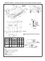
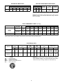
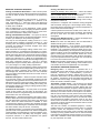
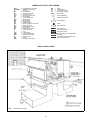
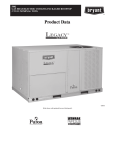
Bryant
Air Conditioning
COMMERCIAL ROOFTOP
PACKAGED HEAT PUMP
Model 542F
Size 180
15 Tons
MODEL 542F
DESCRIPTION
Model 542F is a high-efficiency, single-package heat pump that
has an energy efficiency ratio (EER) of 8.5 and a coefficient of
performance (COP) of 3.0 at 47 F outdoor temperature rating
point.
The 542F has supply- and return-air openings on the bottom of
the unit and is designed primarily for rooftop installation on a
factory-supplied 14- or 24-in. high roof curb. The air ducts connect to the curb only; therefore, the curb and ductwork may be
installed before the unit arrives at the jobsite.
A 24-in. high factory-supplied adapter for horizontal supply/
return duct connections to an over-and-under duct configuration
is also available for grade level or rooftop installation.
‘‘Variable circuited’’ indoor and outdoor coils allow both coils to
operate with parallel circuits when they are performing as
evaporators, and with a series of circuits when they are performing as condensers.
STANDARD FEATURES
FACTORY-ASSEMBLED PACKAGE is a compact, fully selfcontained heating/cooling unit that is prewired, prepiped, and
precharged for minimum installation time and expense.
TWO RUGGED, SERVICEABLE, SEMI-HERMETIC COMPRESSORS provide two stages of heating and cooling. These
compressors are electrically and mechanically independent.
COMPRESSOR ISOLATION MOUNTING minimizes vibration
(noise) transmission to building.
TWO SUCTION-TUBE ACCUMULATORS protect compressors against liquid slugging — permitting operation over wide
range of temperatures.
CRANKCASE HEATERS AND FILTER DRIERS are standard.
HIGH- AND LOW-PRESSURE SAFETY DEVICES are included
to prevent major component breakdown when abnormal refrigerant operating conditions occur.
INTERNAL AND EXTERNAL PROTECTION is provided
against compressor overload and overheat conditions.
HIGH-STATIC, BELT-DRIVEN BLOWER with an adjustable
motor pulley permits variable airflow rates. An optional motor
pulley adjusts the airflow range to meet most applications.
WEATHERIZED CABINET of heavy-duty phosphated and zinccoated steel is standard. Baked-on finish is corrosion and fade
resistant.
VERTICAL CONDENSER AIR DISCHARGE prevents recirculation of hot condenser air and reduces the operating sound
level.
MANUAL OUTDOOR-AIR DAMPER (standard equipment on
units without optional economizer) provides up to 25% outdoor
air for ventilation.
SUPPLEMENTAL ELECTRIC HEATERS are available as accessory equipment for operation on 208, 230, and 460 v, and
are modular in design for easy installation.
SINGLE-POINT POWER CONNECTION is provided on units
with field-installed electric heaters. Only one power supply with
one disconnect switch is required.
PROTECTION AS REQUIRED BY NEC (National Electrical
Code) for fan motors is factory supplied.
TWO-IN. FILTERS are standard.
RIGGING HOLES are provided in unit base rails for a 4-point lift
to facilitate lifting and moving operations.
THERMALLY AND ACOUSTICALLY INSULATED air-handling
section provides quieter and more efficient operation.
FACTORY-INSTALLED OPTIONS
DESCRIPTION AND USAGE
Economizer — The economizer will allow a fixed percentage
(between 0 and 100%) outdoor ventilation air into the unit any
time the indoor fan is running. A dry-bulb changeover thermostat
allows up to 100% outdoor air whenever the temperature of the
outdoor air alone will adequately provide cooling. If the economizer alone cannot provide enough cooling, then simultaneous
economizer and compressor operation will provide the most
economical operation.
SUGGESTED USE:
• To allow a fixed percentage of outdoor air any time the indoor
fan is on, or operates in economizer mode if outdoor air can
provide cooling, but closes when the indoor fan is off to prevent cold backdrafts and wasted energy.
• To reduce energy usage. Use whenever the number of hours
of operation at below 55 F is significant.
• The damper may be used on either vertical or horizontal
applications.
Alternate Indoor-Fan Drive — Alternate drive allows operation
of the indoor fan at conditions outside the range of the standard
factory motor and drive combination.
SUGGESTED USE:
• When higher static/airflow is required to meet job conditions.
Form No. PDS 542F.180.2B
Time GuardT Device — Package consists of a control to be
field wired into the unit controls, and provides a 5-minute delay
in compressor operation between cooling cycles.
SUGGESTED USE:
• Prevents compressor short cycling when rapid compressor
cycles may be a problem.
Electric Heat Packages — Each package consists of one or
more heater modules. Each module slides into keyed mounting
slots in the fan discharge section.
SUGGESTED USE:
• To provide heat in the unit when required.
Economizer — See description listed under Factory-Installed
Options Description and Usage section on page 1.
Remote Control Panel — The remote control panel accessory
consists of a decorative, indoor, wall-mounted panel. The panel
contains: 2-stage heat/2-stage cool thermostat with auxiliary
changeover, a system switch with HEAT-COOL-AUTO.-OFF
settings, a fan switch with ON-AUTO. settings, indicator lights
for HEAT-COOL-FAN operation, and 3 unused indicator lights
for field use.
SUGGESTED USE:
• Whenever remote unit operation is desired.
Emergency Heat Package — The emergency heat package includes an emergency heat control box containing: emergency
heat relays, outdoor thermostat(s), and an emergency heat
thermostat subbase with a warning light.
SUGGESTED USE:
• As auxiliary heating system in the event mechanical heating
should be locked out.
FIELD-INSTALLED ACCESSORY
DESCRIPTION AND USAGE
Roof Curbs (Vertical) — Full-perimeter galvanized steel support frame in 14- and 24-in. high designs provides wood nailer
to attach roof counter flashing. Insulated basepans in curb are
provided to prevent condensation. Ductwork attaches to rails
provided in the roof curb. A gasket is provided to form an airand watertight seal between unit and curb. The gasket meets
the standards of the NRCA (National Roofing Contractors’
Association).
SUGGESTED USE:
• Rooftop application for vertical discharge.
• Slab-mounted applications when elevation of the unit is
necessary.
Horizontal Adapters — The adapters are prefabricated, easily
field-assembled, and permit full perimeter mounting. Adapters
can be installed at the jobsite before unit is installed, eliminating
a major leak source.
SUGGESTED USE:
• Rooftop application for horizontal discharge.
• Rooftop applications for horizontal discharge on units where
high air delivery cfms are required.
Two-Position Damper — Package consists of a low-leak
damper assembly. The damper will allow either 0 or 25% outdoor air into the unit any time the evaporator fan is running.
When the evaporator fan is off, the damper will be closed.
SUGGESTED USE:
• Allows a fixed percentage of outdoor air any time the evaporator fan is on, but closes when the evaporator fan is off to
prevent cold backdrafts and wasted energy.
• The damper may be used on either vertical or horizontal airflow applications.
Thermostats and Subbases — Provide staged cooling and
heating, automatic (or manual) changeover, fan control, and indicator light.
SUGGESTED USE:
• To control unit operations.
Barometric Relief Package — This package is useful when it
is necessary to remove excess pressure from the conditioned
space.
NOTE: Optional economizer is required with this accessory.
Power Exhaust — This package is useful when it is necessary
to remove excess pressure from the conditioned space.
NOTE: Optional economizer is required with this accessory.
SUGGESTED USE:
• When the job requires the ability to relieve internal building
pressure and pressure losses through the return-air ductwork
are greater than 0.20 in. wg.
• When the job requires the ability to move large quantities
of air to relieve pressure in the conditioned space.
Head Pressure Control — Kit consists of an outdoor-air thermostat that permits adequate head pressure control during
cooling operation at low outdoor-ambient temperatures. Refer
to Trade Prices for more details.
SUGGESTED USE:
• When cooling at low-ambient outdoor temperatures is
desired.
CONTENTS
Page
Model Description . . . . . . . . . . . . . . . . . . . . . . . . . . . . . . . . . 3
ARI Capacity Ratings . . . . . . . . . . . . . . . . . . . . . . . . . . . . . . 3
Dimensional Drawings . . . . . . . . . . . . . . . . . . . . . . . . . . . . . 4-6
Specifications . . . . . . . . . . . . . . . . . . . . . . . . . . . . . . . . . . . . 7
Selection Procedure . . . . . . . . . . . . . . . . . . . . . . . . . . . . . . . 8
Gross Cooling Capacities . . . . . . . . . . . . . . . . . . . . . . . . . . . 9
Integrated Heating Capacities . . . . . . . . . . . . . . . . . . . . . . . 9
Air Delivery . . . . . . . . . . . . . . . . . . . . . . . . . . . . . . . . . . . . . 10
Electric Resistance Heater Data . . . . . . . . . . . . . . . . . . . . . 11
Electrical Data . . . . . . . . . . . . . . . . . . . . . . . . . . . . . . . . . . . 11
Operating Sequence . . . . . . . . . . . . . . . . . . . . . . . . . . . . . . 12
Application Data . . . . . . . . . . . . . . . . . . . . . . . . . . . . . . . . . 13
Typical Field Wiring . . . . . . . . . . . . . . . . . . . . . . . . . . . . . 14,15
Typical Installation . . . . . . . . . . . . . . . . . . . . . . . . . . . . . . . . 15
Engineers’ Specification Guide . . . . . . . . . . . . . . . . . . . . . . 16
2
MODEL DESCRIPTION
ODS CATALOG ORDERING NUMBER NOMENCLATURE
ARI* CAPACITY RATINGS
Total
kW
21.0
COOLING
Net
Capacity
Cfm
(Btuh)
162,000
6750
EER
8.5
HEATING-HIGH TEMP
Total
Total
Capacity
COP
kW
(Btuh)
166,000
17.5
2.8
LEGEND
COP
db
EER
ESP
kW
wb
—
—
—
—
—
—
HEATING-LOW TEMP
Total
Total
Capacity
COP
kW
(Btuh)
92,000
14.3
1.8
Cooling ratings are net values, reflecting the effects of circulating fan
heat. Ratings are based on:
ESP: −.35 in. wg
Cooling Standard: 80 F db, 67 F wb indoor coil entering-air temperature and 95 F outdoor coil entering-air temperature.
High-Temp Heating Standard: 70 F db indoor coil entering-air temperature and 47 F db, 43 F wb outdoor coil entering-air temperature.
Low-Temp Heating Standard: 70 F db indoor coil entering-air temperature and 17 F db, 15 F wb outdoor coil entering-air temperature.
Coefficient of Performance
Dry Bulb
Energy Efficiency Ratio
External Static Pressure
Kilowatts
Wet Bulb
*Air Conditioning and Refrigeration Institute.
NOTE: 542F180 units are rated in accordance with ARI Standard 340.
3
DIMENSIONAL DRAWING — BASE UNIT
NOTE: Space required for service clearance and airflow: Allow 68-09 above the unit; 78-09 on filter access panel end; and 48-09 on
remaining sides of unit.
4
DIMENSIONAL DRAWING — HORIZONTAL AND VERTICAL ROOF CURBS AND HORIZONTAL ADAPTER
NOTE: To prevent the hazard of stagnant water build-up in the
drain pan of the indoor-air section, unit can only be pitched as
shown.
ACCESSORY
CURB
DESCRIPTION
PACKAGE NO. HEIGHT
18-29
Standard Curb —
308450-201
(305)
149 High
Standard
Curb
28-09
308450-202
Units Requiring
(610) for
High Installation
308450-203
28-09
(610)
389210-201
18-119
(584)
Horizontal
Roof Curb
Pre-Assembled,
High-Static
Horizontal
Adapter
‘‘A’’
‘‘B’’
‘‘C’’
—
—
—
—
—
—
58-69 08-21⁄29
(1676) (64)
18-69
(457)
68-29 08-61⁄49 18-25⁄89
(1880) (159) (371)
LEGEND
COMP SECT. — Compressor Section
NOTES:
1. Roof curb accessory is shipped unassembled.
2. Insulated panels, 1⁄2-in. thick neoprene-coated,
2 lb density.
3. Dimensions in ( ) are in millimeters.
4.
Direction of airflow.
5. Roof curb: 18 gage steel.
6. Attach all ductwork to roof curb.
5
DIMENSIONAL DRAWING — HORIZONTAL ADAPTER INSTALLATION
NOTE: 389210-201 is a fully factory preassembled horizontal
adapter which includes an insulated high static regain transition duct
and substantially improves fan static performance.
6
SPECIFICATIONS
UNIT 542F
OPERATING WT (lb)
Unit
with Economizer
Roof Curb
COMPRESSOR
Quantity...Type
Oil (oz)
Capacity Steps
REFRIGERANT (Capillary Control)
Charge (lb) Sys 1*, Sys 2
OUTDOOR COIL
Rows
Fins/in.
Total Face Area (sq ft)
OUTDOOR-AIR FAN
Nominal Cfm
Quantity...Diameter (in.)
Motor Hp (1100 Rpm)...kW Input
INDOOR COIL
Total Face Area (sq ft)
Rows...Fins/in.
INDOOR-AIR FAN
Quantity...Size (in.)
Nominal Cfm
Rpm Range
Max Allowable Rpm
Fan Pulley Pitch Diameter (in.)
Motor Pulley Pitch Diameter (in.)
Motor Frame Size
Belt, Quantity...Type
Speed Change per Full Turn of
Moveable Pulley Flange (Rpm)
Moveable Pulley Maximum Full
Turns from Closed Position
Factory Setting — Full Turns Open
Factory Speed Setting (Rpm)
180 (15 TON)
1760
1870
200
Semi Hermetic, 4 Cyl
2...06D
112 ea
0, 50, 100
R-22
16.8, 16.8
Copper Tube, Aluminum Plate Fins
3
13.6
22.2
Propeller Type, Direct Drive
12,000
2...26
1...2.2
Copper Tube, Aluminum Plate Fins
18.3
3...14.4
Centrifugal, Adjustable Belt Drive
2...10 x 10
6000
916-1186
1158-1428
1550
6.4
3.4-4.4
4.3-5.3
56
—
1...A44
1...B45
54
Std
Alt
Std
Alt
Std
Alt
Std
Alt
5
5
916
1158
3...3500
Std
Alt
Motor (1750 Rpm), Hp...Max Watts
HIGH-PRESSURE SWITCH
Cutout (psig)
Reset (psig)
LOSS-OF-CHARGE/LOW-PRESSURE SWITCH
(Liquid Line)
Cutout (psig)
Reset (psig)
INDOOR-AIR FILTERS, Type
Quantity...Size (in.)
426
320
7
22
10% Efficient — Throwaway Fiberglass
4...20 x 20 x 2
4...16 x 20 x 2
*System 1 consists of upper portion of outdoor coil and lower portion of indoor coil, and System 2 consists of the upper
portion of the indoor coil and the lower portion of the outdoor coil.
7
SELECTION PROCEDURE (with example)
IV DETERMINE FAN SPEED AND POWER REQUIREMENTS AT DESIGN CONDITIONS:
Before entering the Air Delivery table calculate the total
static pressure required based on unit components. From
the given and the Pressure Drop tables, find:
External static pressure
0.75 in. wg
Economizer
0.07 in. wg
Electric heat
0.09 in. wg
Total static pressure
0.91 in. wg
I DETERMINE COOLING AND HEATING REQUIREMENTS AT DESIGN CONDITIONS:
Given:
Required Cooling Capacity (TC) . . . . . . . . . 172,000 Btuh
Sensible Heat Capacity (SHC) . . . . . . . . . . 133,000 Btuh
Required Heating Capacity . . . . . . . . . . . . . 170,000 Btuh
Outdoor Entering-Air Temperature . . . . . . . . . . . . . . 95 F
Indoor Entering-Air Temperature
(Cooling) . . . . . . . . . . . . . 80 F entering dry bulb (edb)
67 F entering wet bulb (ewb)
Outdoor Coil Entering Air Temperature (Heating) . . . 0° F
Indoor-Air Winter Design Temperature . . . . . . . . . . . 70 F
Evaporator Air Quantity . . . . . . . . . . . . . . . . . . . 6000 cfm
External Static Pressure (ESP) . . . . . . . . . . . 0.75 in. wg
Electrical Characteristics (V-Ph-Hz) . . . . . . . . . . 230-3-60
Enter the Air Delivery table on page 10. At 6000 cfm, the
standard motor with alternate drive will deliver up to
1.40 in. wg static pressure and 3.82 brake horsepower
(bhp). This will adequately handle job requirements.
V DETERMINE NET CAPACITIES:
Capacities are gross and do not include the effect of
indoor-fan motor (IFM) heat.
Determine net cooling capacity as follows:
Convert bhp to Watts using the formula found in the note
following the Air Delivery table on page 10.
For example:
746 x Bhp
Watts =
Motor Efficiency
746 x 3.82
Watts =
.81
Watts = 3518
II SELECT UNIT BASED ON REQUIRED COOLING
CAPACITY:
Enter Gross Cooling Capacities table on page 9 at outdoor
entering-air temperature of 95 F, indoor air entering at
6000 cfm and 67 F ewb. The 542F unit will provide a total
cooling capacity of 185,400 Btuh and a sensible heat capacity of 146,700 Btuh.
For indoor-air temperature other than 80 F edb, calculate
sensible heat capacity correction, as required, using the
formula found in Note 3 following the cooling capacities
table.
NOTE: Unit ratings are gross capacities and do not include
the effect of indoor-fan motor heat. To calculate net capacities, see Step V.
Net capacity = Gross capacity – IFM heat
= 185,400 Btuh – (3518 Watts
x 3.413 Btuh/Watts)
= 185,400 Btuh – 12,007 Btuh
= 173,393 Btuh
III SELECT ELECTRIC HEAT:
Enter the Integrated Heating Capacities table on page 9 at
6000 cfm. At 70 F return air and 0° F air entering outdoor
coil, the integrated heating capacity is 67,000 Btuh. (Deductions for outdoor-coil frost and defrosting have already
been made. No correction is required.)
The required heating capacity is 170,000 Btuh. Therefore,
103,000 Btuh (170,000 – 67,000 Btuh) additional electric
heat is required.
Determine additional electric heat capacity in kW.
103,000 Btuh
= 30.2 kW of heat required.
3413 Btuh/kW
Enter the Electric Resistance Heater Data table on page 11
for 542F at 230-3-60. The 31.0-kW heater at 230 v most
closely satisfies the heating required.
31.0 kW x 3413 Btuh/kW = 105,800 Btuh
Total unit heating capacity at 0° F is 172,800 Btuh
(105,800 + 67,000).
Net sensible capacity = 146,700 Btuh – 12,007 Btuh
= 134,693 Btuh
Determine net heating capacity as follows:
Net capacity = Gross capacity + IFM heat
+ Electric heat capacity
= 67,000 Btuh + 12,007 Btuh
+ 105,800 Btuh
= 184,807 Btuh
8
GROSS COOLING CAPACITIES
UNIT 542F180
Outdoor Air (F)
Indoor Air
Cfm
BF
5500
.07
6000
.08
7000
.09
Ewb
(F)
62
67
72
62
67
72
62
67
72
85
Capacity
MBtuh
Total Sensible
176.1
169.7
191.4
142.6
207.1
111.2
180.0
176.8
194.3
148.9
209.7
115.2
186.3
184.6
198.4
158.6
213.3
121.3
Compr
kW
13.9
14.6
15.3
14.0
14.6
15.2
13.8
14.3
15.0
95
Capacity
MBtuh
Total Sensible
167.2
165.4
182.7
139.9
199.8
109.4
171.4
161.9
185.4
146.7
202.3
113.3
178.3
178.3
189.4
156.6
205.9
119.7
Compr
kW
14.9
15.6
16.4
14.9
15.6
16.4
14.8
15.4
16.2
LEGEND
BF
— Bypass Factor
Edb — Entering Dry Bulb
Ewb — Entering Wet Bulb
kW — Compressor Power Input
SHC — Sensible Capacity
NOTES:
1. Direct interpolation is permissible. Do not extrapolate.
2. The following formula may be used:
sensible capacity (Btuh)
tldb = tedb −
1.10 x cfm
tlwb = Wet-Bulb temperature corresponding to enthalpy of air
leaving indoor coil (hlwb)
total capacity (Btuh)
hlwb = hewb −
4.5 x cfm
Where: hewb = Enthalpy of air entering indoor coil.
105
Capacity
MBtuh
Total Sensible
158.0
157.9
171.4
130.1
189.3
106.0
162.5
162.5
173.9
143.0
191.6
110.2
169.1
169.1
178.0
153.1
195.2
117.0
Compr
kW
16.0
16.6
17.6
16.1
16.6
17.5
16.0
16.4
17.3
115
Capacity
MBtuh
Total Sensible
148.4
148.4
159.0
130.8
176.9
102.0
152.7
152.7
161.5
137.4
179.0
106.3
158.9
158.9
165.4
147.5
182.6
113.2
Compr
kW
17.7
17.7
18.6
17.3
17.7
18.6
17.2
17.5
18.4
3. The SHC is based on 80 F edb temperature of air entering indoor
coil.
Below 80 F edb, subtract (correction factor x cfm) from SHC.
Above 80 F edb, add (correction factor x cfm) to SHC.
BF
79
81
.03
.10
.15
.20
1.06
.98
.93
.87
ENTERING AIR DRY-BULB TEMP (F)
78
77
76
75
Under 75
Over 85
82
83
84
85
Correction Factor
2.11
3.17
4.33
5.28
1.96
2.94
3.92
4.91
use formula
1.85
2.78
3.71
4.63
shown below
1.74
2.62
3.49
4.36
Interpolation is permissible. Do not extrapolate.
Correction Factor = 1.10 x (1 − BF) x (edb − 80).
INTEGRATED HEATING CAPACITIES
OUTDOORAIR TEMP
(F db at
70% RH)
60
50
40
30
20
10
0
−10
−20
INTEGRATED
TOTAL POWER
CAPACITY
INPUT (kW)
(MBtuh)*
Indoor-Air Temp (F edb)
55
70
80
55
70
80
Indoor Airflow (cfm)
5500
218 208 198 18.5 19.6 20.2
189 180 171 16.9 17.8 18.3
163 155 147 15.5 16.3 16.8
121 115 109 14.5 15.3 15.8
105 100
95 13.7 14.4 14.8
89
85
81 12.7 13.4 13.8
69
66
63 11.5 12.1 12.5
51
49
47 10.4 10.9 11.2
44
42
40
9.2
9.7 10.0
INTEGRATED
TOTAL POWER
CAPACITY
INPUT (kW)
(MBtuh)*
Indoor-Air Temp (F edb)
55
70
80
55
70
80
Indoor Airflow (cfm)
6000
221 210 200 18.5 19.5 20.1
192 183 174 17.0 17.9 18.4
165 157 149 15.8 16.6 17.1
122 116
110 14.7 15.5 16.0
107 102
97 14.1 14.8 15.2
91
87
83 13.3 14.0 14.4
70
67
64 11.7 12.3 12.7
53
50
48 10.5 11.1
11.4
46
44
42
9.4
9.9 10.2
LEGEND
ARI — Air Conditioning and Refrigeration Institute
Edb — Entering Dry Bulb
kW — Total Unit Power Input — Includes compressors, outdoor-fan
motors, and indoor-fan motor. Indoor-fan motor heat based
on unit operating at cfm shown and external static pressures
(ESP) of 0.35.
Conversion formula: Btuh = kW x 3413
*Includes effect of defrost and indoor-fan motor heat at ARI conditions.
9
INTEGRATED
TOTAL POWER
CAPACITY
INPUT (kW)
(MBtuh)*
Indoor-Air Temp (F edb)
55
70
80
55
70
80
Indoor Airflow (cfm)
7000
230 219 208 19.6 19.6 20.2
201 191 181 17.2 18.1 18.6
174 166 158 16.1 16.9 17.4
129 123 117 15.0 15.8 16.3
114 109 104 14.4 15.2 15.7
99
94
89 13.8 14.5 14.9
80
76
72 12.0 12.6 13.0
61
58
55 10.9 11.5
11.8
54
51
48
9.9 10.4 10.7
AIR DELIVERY
CFM
5500
6000
6500
7000
0.20
Rpm
Bhp
923
1.88
993
2.36
1064
2.92
1136
3.55
0.40
Rpm
Bhp
1002
2.13
1066
2.63
1131
3.21
1199
3.86
EXTERNAL STATIC PRESSURE (in. wg)
0.60
0.80
1.00
1.20
Rpm
Bhp
Rpm
Bhp
Rpm
Bhp
Rpm
Bhp
1075
2.35
1143
2.58
1208
2.80
1271
3.01
1135
2.88
1200
3.12
1260
3.36
1320
3.59
1197
3.48
1259
3.74
1318
4.00
—
—
—
—
—
—
—
—
—
—
LEGEND
Bhp — Brake horsepower
1.60
Rpm
Bhp
1394
3.49
—
—
—
—
—
—
5. Electric heater pressure drop must be accounted for in fan rpm and
bhp section (see Static Pressure Losses table on page 11).
6. Minimum cfm for units with electric resistance heat: 5650 cfm.
Converting Bhp to Watts:
Bhp x 746
Watts input =
Motor Efficiency
Approximate Motor Efficiency: .81
NOTES:
1.
1.40
Rpm
Bhp
1334
3.24
1378
3.82
—
—
—
—
— Alternate drive required.
2.
indicates maximum capability of standard drive.
3. Maximum allowable fan speed is 1550 rpm.
4. Fan performance is based on wet coil and clean 2-in. filters. Casing
losses have been deducted.
AIR DELIVERY USING ACCESSORY POWER EXHAUST
HORIZONTAL SUPPLY/RETURN FAN PERFORMANCE
WITH 389210-201 HIGH STATIC REGAIN ADAPTER
NOTE: The 389210-201 horizontal supply/return adapter accessory
improves 542F180 fan performance by increasing external static
pressure by amount shown above.
NOTE: The 389210-201 high static regain adapter accessory may
be used to provide horizontal supply/return.
10
INDOOR FAN DRIVE DATA
FAN RPM
Turns Open
2
3
1079
1029
1321
1267
TYPE
0
1186
1428
Std
Alt
1
1132
1374
ELECTRIC RESISTANCE HEATER DATA
4
970
1213
HEATER kW*
Unit Voltages
208
230
460
26
31
32
42
52
55
56
69
80
5
916
1158
HEATING
STAGES
% HEAT
PER STAGE
MAXIMUM
STAGES†
2
2
2
50/50
33/67
50/50
2
3
4
*Field-installed accessory only.
†Maximum number of stages using accessory outdoor-air thermostats.
NOTE: Heater kW is based on heater voltage of 240 v or 480 v. If power
distribution voltage to unit varies from rated heater voltage, heater kW
will vary accordingly.
STATIC PRESSURE LOSSES* (in. wg)
ACCESSORY/FIOP
UNIT
VOLTAGE
208/230-3-60
Electric
Heaters
460-3-60
Economizer
All
CFM
kW
26/31
42/52
56/69
32
55
80
—
3500
.04
.05
.06
.04
.05
.06
.02
4000
.05
.06
.07
.05
.06
.07
.03
4500
.06
.07
.08
.06
.07
.08
.04
5000
.07
.08
.10
.07
.08
.10
.05
5500
.08
.10
.12
.08
.10
.12
.06
6000
.09
.12
.15
.09
.12
.15
.07
6500
.11
.14
.17
.11
.14
.17
.08
7000
.12
.16
.20
.12
.16
.20
.09
FIOP — Factory-Installed Option
*Static pressure losses must be added to external static pressure before entering Air Delivery table.
ELECTRICAL DATA
V-PH-HZ
VOLTAGE
RANGE
COMPRESSOR
(each)
OUTDOOR
FAN
MOTOR
Qty
FLA
INDOOR
FAN
MOTOR
Hp
FLA
Min
Max
RLA
LRA
208/230-3-60
187
254
31.3
137
2
7.7
3.0
10.5
460-3-60
414
508
15.7
62
2
3.3
3.0
4.8
LEGEND
FLA
LRA
MCA
MOCP
RLA
—
—
—
—
—
ELECTRIC
HEAT
kW†
—
26/31
42/52
56/69
—
32
55
80
FLA
—
72/ 82
117/135
156/180
—
39
66
96
POWER SUPPLY*
MCA
97/ 97
186/199
243/231
252/276
47
96
113
143
MOCP
125/125
200/200
250/250
300/300
60
100
125
150
*Fuse only.
†Heater capacity (kW) is based on heater voltage of 240 v or 480 v. If
power distribution voltage to unit varies from rated heater voltage,
heater kW will vary accordingly. Heaters are field-installed only.
Full Load Amps
Locked Rotor Amps
Minimum Circuit Amps
Maximum Overcurrent Protection
Rated Load Amps
11
OPERATING SEQUENCE
Cooling, Units With Economizer
Outdoor Air Enthalpy Above Set Point — Indoor and outdoor
fans and compressors energize when there is a call for cooling.
The economizer damper moves to VENT position.
Outdoor Air Enthalpy Below Set Point — Indoor fan starts and
economizer damper opens fully on a first-stage call for cooling.
Compressor remains off.
Compressor is energized and mechanical cooling integrates
with economizer cooling upon a second stage call for cooling.
Economizer damper modulates when mixed-air temperature is
below mixed-air thermostat setting.
A freeze protection thermostat is located on the indoor coil. It
detects ice build-up and turns off the compressor, thus allowing
the coil to clear. Once ice melts, the compressor can be
reenergized.
Heating, Units With Economizer — Outdoor-air damper stays
at VENT position while indoor-air fan runs.
NOTE: If fan switch is at ON position, and room thermostat is
satisfied, damper goes to ventilation position.
Cycle-LOC™ Protection — If unit operation is interrupted by
an open high-pressure switch, low-pressure switch, indoor-coil
freezestat, or by compressor internal line-break device (overcurrent or overtemperature), and compressor is calling for either
cooling or heating, Cycle-LOC simultaneously locks out unit and
lights a warning light on the thermostat. Restart the unit by
manually turning room thermostat to OFF and then ON position.
If any of the protective devices opens again, the unit continues
to lock out until corrective action is taken.
NOTE: If the unit fails to operate due to compressor overcurrent
condition, restart by manually resetting circuit breakers at the
unit. Restart cannot be accomplished at room thermostat.
BASE UNIT OPERATING SEQUENCE
Cooling, Units Without Economizer — With unit main power
on, set thermostat at COOL position and desired room temperature. Set fan switch at AUTO. (on demand) or ON (continuous)
position.
On a rise in room temperature, cooling contact no. 1 in the thermostat closes, energizing compressor no. 1 contactor on all
units. Compressor no. 1, indoor-fan motors, and outdoor-fan
motors start. Compressor no. 1 cycles on demand of thermostat
to satisfy room conditions.
With an additional rise in room temperature, cooling contact
no. 2 in the thermostat closes, energizing compressor contactor
no. 2. Compressor no. 2 starts. Compressor no. 2 cycles on demand of the thermostat to satisfy room conditions.
Heating, Units Without Economizer — Turn power on and set
thermostat at HEAT position and desired temperature. Set fan
at AUTO. (on demand) or ON (continuous) position.
On a drop in room temperature, heating contact no. 1 in the
thermostat closes, energizing compressor contactor no. 1 and
reversing valve, and starting compressor no. 1. Indoor blower
contactors and outdoor-fan contactors energize at the same
time for heat pump cycle.
When thermostat second-stage heating contacts close, compressor contactor no. 2 energizes and compressor no. 2 starts.
Units have a built-in electric resistance heat lockout through the
defrost thermostat. Above 40 F (approximate) outdoor temperature, electric resistance heat is locked out and second-stage
heat is from compressor no. 2. Below 40 F (approximate) ambient temperature, when the thermostat first-stage heating contacts close, compressor contacts no. 1 and no. 2 energize
sequentially through a time delay. Both compressors (no. 1 and
no. 2) are brought on to satisfy heating requirements.
On a further drop in room temperature (outdoor ambient below
40 F), the thermostat second-stage heating contacts close, energizing the electric resistance heat contactor and starting
second-stage heat. Electric heaters with 2 or more contactors
can have outdoor thermostats wired into the control circuit for
additional staging.
Automatic Changeover — When the system selection switch
is set at AUTO. position, unit automatically changes from heat
operation to cooling operation when the temperature of the conditioned space rises to cooling lever setting. When the temperature of the conditioned space falls to heating lever setting, unit
automatically changes from cooling to heating operation (with a
3 F deadband in between).
Continuous Air Circulation — Turn unit power on. Set system
control at OFF position. Set fan switch at ON position. The
indoor-fan contactor is energized through the thermostat switch
and the indoor fan runs continuously.
Defrost Cycle — The defrost thermostat on the outdoor coil activates a defrost timer which energizes electric resistance heaters and deenergizes reversing valve relays and outdoor-fan
motors. When the defrost thermostat is satisfied or when
10 minutes have elapsed, reversing valve solenoids energize
and electric heaters deenergize. The defrost timer will energize
the electric heaters every 90 minutes, if necessary.
The defrost thermostat, in conjunction with a time-delay relay,
prevents electric heat operation above an ambient temperature
of approximately 40 F (depending on coil frost conditions). If defrost thermostat closes, time-delay relay energizes, closing
compressor contactor no. 2. Both compressors now operate
from W1, and W2 controls electric heat.
ACCESSORY OPERATING SEQUENCES
Emergency Heat — If compressor is inoperative due to a
tripped safety device (high-pressure, low-pressure, indoor-coil
freezestat, overcurrent, or overtemperature), Cycle-LOC™
locks out compressor and lights a warning light on the room
thermostat. When switch is on (thermostat is moved to the EM
HT position), compressor circuit and outdoor thermostats are
bypassed, and second stage of thermostat energizes indoor
blower and electric resistance heaters.
Time GuardT Control Circuit — The accessory Time Guard
control circuit provides a 5-minute delay of compressor restart
after desired space temperature has been attained and room
thermostat has shut down the compressor. Assuming that compressor has been off for at least 5 minutes due to room thermostat action, Time Guard control circuit sequence is as follows:
With fan selector switch at AUTO. position and a call for cooling
from the room thermostat, indoor blowers start immediately;
outdoor-air fans and compressor start 15 seconds later. When
room thermostat is satisfied, compressor shuts off. The Time
Guard control circuit timer motor then runs for 4 minutes and
45 seconds, at which point its internal switches reset so normal
sequence can begin again.
The base unit contains, as standard equipment, a factoryinstalled Cycle-LOC compressor protection device. If overload
protector causes the compressor to shut off, compressor
remains locked out until control circuit is manually reset. Reset
manually by moving system selector lever on room thermostat
to OFF position momentarily and then returning it to cooling position. After a standard 5-minute Time Guard control circuit delay, the compressor can restart.
12
APPLICATION DATA
1. Ductwork must be attached to the curb on all units. Interior
installation may proceed before unit is set in place on roof.
Field-fabricated concentric ductwork may be connected as
shown below.
2. Factory- and field-installed electric heat allows single power
entry to unit for both heating and cooling. Values shown for
minimum circuit amps (MCA) and maximum overcurrent
protection (MOCP) in the Electrical Data table on page 11
apply to factory- or field-installed heaters.
3. Indoor coil is draw-thru configuration. Condensate trap
(minimum 4 in. deep) must be field-installed prior to start-up
on cooling cycle. Install plug in condensate drain on opposite side of unit from trap.
4. When return-air ductwork systems are used, return horizontal static pressures should be limited to 0.4 in. wg.
5. Cfm and other values indicated throughout this literature illustrate the operating range of the equipment. Operation
outside these limits is not recommended.
6. When use is required with emergency heat, in addition to
accessory emergency-heat components, field-supplied
7.
8.
9.
10.
11.
emergency heat switch (DPST toggle switch) must be
used. Emergency heat subbase cannot be used with the remote control panel.
Units are designed to operate at outdoor temperatures
down to 40 F. At temperatures below 40 F, accessory head
pressure control device will permit operation at outdoor
temperatures as low as −20 F.
All roof curb and adapter installations must be counterflashed to prevent water leakage.
Select unit based on cooling only. Do not select heat pumps
on heating capacity. Add auxiliary resistance heat if
required.
Electric power may be brought to unit within curb perimeter
through fittings provided in basepan. Provide power supply
in accordance with local codes. Branch circuit protection to
unit must be provided by fuses no larger than MOCP shown
in Electrical Data table on page 11.
The 24-v control wiring to thermostat is NEC (National Electrical Code) Class II.
Shaded area indicates block-off panels.
NOTE: Do not drill in this area, damage to basepan may result in
water leak.
NOTE: Dimensions A, A8 and B, B8 are obtained from fieldsupplied ceiling diffuser.
Concentric Duct Air Distribution
Concentric Duct Details
OPTIONS AND ACCESSORIES
ITEM
Alternate Drive
Integrated Economizer
Electric Heater
Emergency Heat Package
Roof Curb (Vertical and Horizontal)
Horizontal Adapter
Remote Control Panel
Thermostats and Subbases
Time GuardT Control Device
Power Exhaust
Two-Position Damper
Barometric Relief Damper
Head Pressure Control
OPTION*
X
X
*Factory Installed.
†Field Installed.
13
ACCESSORY†
X
X
X
X
X
X
X
X
X
X
X
X
TYPICAL FIELD WIRING
14
LEGEND FOR TYPICAL FIELD WIRING
AHA
— Adjustable Heat Anticipator
BKR W/AT — Breaks With Amp Turns
C
— Contactor
CB
— Circuit Breaker
CC
— Cooling Compensator
CLO
— Cooling Lockout
CLS
— Cooling Lockout Switch
CR
— Control Relay
CT
— Current Transformer
DFR
— Defrost Relay
DM
— Damper Motor
DR
— Damper Relay
EC
— Enthalpy Control
FPT
— Freeze Protection Thermostat
HC
— Heater Contactor
HPS
— High-Pressure Switch
HR
— Heater Relay
IFC
— Indoor Fan Contactor
IP
— Internal Protector
L
— Light
LOR
— Lockout Relay
LPS
— Low-Pressure Switch
MAT
— Mixed Air Thermostat
PL
— Plug Assembly
PRI
— Primary
RVR
— Reversing Valve Relay
SW
TB
TC
TH
TRAN
—
—
—
—
—
Switch
Terminal Block
Thermostat, Cooling
Thermostat, Heating
Transformer
Terminal (Marked)
Terminal (Unmarked)
Terminal Block
Splice
Splice (Marked)
Factory Wiring
Field Control Wiring
Field Power Wiring
Accessory Wiring or Optional Wiring
Accessory
To indicate common potential only;
Not to represent wiring.
TYPICAL INSTALLATION
NEC — National Electrical Code
15
ENGINEER’S SPECIFICATION GUIDE
GENERAL: Furnish and install a self-contained, air-to-air electric heat pump rooftop unit with supply- and return-air connections off the bottom of the unit, mounted on a full perimeter, fieldassembled roof curb. The rooftop unit shall be completely
factory-assembled and tested, and shall include compressors,
indoor coil, outdoor coil, fans and motors, interconnecting wiring, prewired control panel, filters, and other necessary components mounted in a corrosion-resistant all-weather cabinet. Unit
shall be shipped fully charged with oil and R-22 refrigerant.
COOLING CAPACITY: Total net cooling capacity of the unit
shall be
Btuh or greater, and sensible capacity shall be
Btuh or greater at conditions of
ft3/min evaporator entering air of 67 F wet bulb, 80 F dry bulb, and condenser
entering air temperature of 95 F dry bulb. Equipment must have
an EER of 8.5 or higher at this condition.
HEATING CAPACITY: Total heating capacity shall be
Btuh or greater (integrated rating) when rated at
F dry bulb outdoor ambient with
ft3/min and
F air entering indoor (heating) coil. The equipment must
have a minimum heating COP of 3.0 at 47 F dry bulb outdoor
ambient (high temp) and 2.1 at 17 F dry bulb outdoor ambient
(low temp). Supplemental heat of
kW shall be provided
to satisfy heat loss at winter design conditions. The coefficient of
performance (COP) must be 2.9 or better at 47 F.
CABINET: The cabinet shall be constructed of heavy-gage zinccoated galvanized steel with baked enamel finish. This finish
shall exceed the U.S. Army Corps of Engineers standards without peeling, cracking, or rusting beyond 1⁄8 in. on a scratch mark
when subjected to 5% salt spray solution at 95 F for 1000 hours.
The cabinet shall be constructed such that one-piece top is
used for the entire indoor air-handling section to ensure watertightness. Two-in. replaceable filters mounted internally shall be
supplied.
COMPRESSORS: Compressors shall be of the serviceable,
semi-hermetic type, with crankcase heaters and suitable vibration isolators. A separate refrigerant circuit shall be provided for
each compressor. An automatic resetting circuit shall be provided to prevent rapid compressor cycling.
OUTDOOR SECTION: The outdoor coil shall be constructed of
aluminum plate fins mechanically bonded to seamless copper
tubes. Outdoor fans shall be direct-driven, slow-speed propeller
type for quiet operation and shall be mounted for vertical discharge. The outdoor motors shall be protected as required by
NEC and be supplied with rainshields.
Bryant
Air Conditioning
Copyright 1995 Carrier Corporation
INDOOR SECTION: Indoor coil shall be constructed of aluminum plate fins mechanically bonded to seamless copper tubes.
Indoor blower shall be of centrifugal type, forward curved. The
blower shall be belt-driven by means of an adjustable pitch pulley, permitting a variation of airflow by means of blower speed
adjustment. Blower motor shall be electrically protected as required by NEC. Blower motor shall be mounted on the adjustable base, allowing for proper alignment and tension. The steel
shaft shall rotate in prelubricated bearings.
CONTROL CIRCUIT: The unit control panel shall be prewired in
the unit casing furnished with a 24-v control transformer, highand low-pressure switches, compressor, outdoor and indoor fan
motor contactors, as well as other protective devices. The defrost circuit shall be time and temperature initiated. A
90-minute timer shall energize the defrost cycle only if the coil
temperature indicates a frost condition. Defrost shall terminate
after 10 minutes of operation, or when a satisfactory coil temperature is achieved to minimize defrost operating time.
APPROVALS: The unit shall be ETL tested and certified. All wiring shall be in accordance with NEC, and units shall meet
ASHRAE Standard 62. The unit shall be rated in accordance
with ARI Standard 340. Units shall be designed to conform to
NRCA standards. Insulation and adhesive shall meet NFPA 90A
requirements for flame spread and smoke generation.
OPTIONS: Factory-installed integrated economizer shall include all hardware and controls to provide cooling using outdoor
air alone, or in conjunction with mechanical cooling. Dampers
shall be low leakage type, not to exceed 2% leakage at
1.0 in. wg pressure differential. Economizer shall be capable of
introducing up to 100% outdoor air and shall be equipped with a
gravity relief damper. Economizer controls shall be dry-bulb
type.
On all units where the factory-installed economizer is not chosen, the factory-installed manual outdoor-air damper shall be included. In addition, a factory-installed alternate indoor-fan drive
is available.
ACCESSORIES: Field-installed accessories shall include:
Economizer, vertical and horizontal roof curbs (14 or 24 in.),
horizontal adapter, two-position damper, Time GuardT short
cycle circuit protection, thermostats and subbases, electric
heaters, barometric relief damper, power exhaust, emergency
heat, remote control panel, and head pressure control device.
SPECIFICATIONS SUBJECT TO CHANGE WITHOUT NOTICE
UNIT MUST BE INSTALLED IN ACCORDANCE
WITH INSTALLATION INSTRUCTIONS
Printed in U.S.A.
5/95
CATALOG NO. BY-3254-205