1
Time GuardT Device — Package consists of a control to be
field wired into the unit controls, and provides a 5-minute delay
in compressor operation between cooling cycles.
SUGGESTED USE:
• Prevents compressor short cycling when rapid compressor
cycles may be a problem.
Electric Heat Packages — Each package consists of one or
more heater modules. Each module slides into keyed mounting
slots in the fan discharge section.
SUGGESTED USE:
• To provide heat in the unit when required.
Economizer — See description listed under Factory-Installed
Options Description and Usage section on page 1.
Remote Control Panel — The remote control panel accessory
consists of a decorative, indoor, wall-mounted panel. The panel
contains: 2-stage heat/2-stage cool thermostat with auxiliary
changeover, a system switch with HEAT-COOL-AUTO.-OFF
settings, a fan switch with ON-AUTO. settings, indicator lights
for HEAT-COOL-FAN operation, and 3 unused indicator lights
for field use.
SUGGESTED USE:
• Whenever remote unit operation is desired.
Emergency Heat Package — The emergency heat package includes an emergency heat control box containing: emergency
heat relays, outdoor thermostat(s), and an emergency heat
thermostat subbase with a warning light.
SUGGESTED USE:
• As auxiliary heating system in the event mechanical heating
should be locked out.
FIELD-INSTALLED ACCESSORY
DESCRIPTION AND USAGE
Roof Curbs (Vertical) — Full-perimeter galvanized steel support frame in 14- and 24-in. high designs provides wood nailer
to attach roof counter flashing. Insulated basepans in curb are
provided to prevent condensation. Ductwork attaches to rails
provided in the roof curb. A gasket is provided to form an airand watertight seal between unit and curb. The gasket meets
the standards of the NRCA (National Roofing Contractors’
Association).
SUGGESTED USE:
• Rooftop application for vertical discharge.
• Slab-mounted applications when elevation of the unit is
necessary.
Horizontal Adapters — The adapters are prefabricated, easily
field-assembled, and permit full perimeter mounting. Adapters
can be installed at the jobsite before unit is installed, eliminating
a major leak source.
SUGGESTED USE:
• Rooftop application for horizontal discharge.
• Rooftop applications for horizontal discharge on units where
high air delivery cfms are required.
Two-Position Damper — Package consists of a low-leak
damper assembly. The damper will allow either 0 or 25% outdoor air into the unit any time the evaporator fan is running.
When the evaporator fan is off, the damper will be closed.
SUGGESTED USE:
• Allows a fixed percentage of outdoor air any time the evaporator fan is on, but closes when the evaporator fan is off to
prevent cold backdrafts and wasted energy.
• The damper may be used on either vertical or horizontal airflow applications.
Thermostats and Subbases — Provide staged cooling and
heating, automatic (or manual) changeover, fan control, and indicator light.
SUGGESTED USE:
• To control unit operations.
Barometric Relief Package — This package is useful when it
is necessary to remove excess pressure from the conditioned
space.
NOTE: Optional economizer is required with this accessory.
Power Exhaust — This package is useful when it is necessary
to remove excess pressure from the conditioned space.
NOTE: Optional economizer is required with this accessory.
SUGGESTED USE:
• When the job requires the ability to relieve internal building
pressure and pressure losses through the return-air ductwork
are greater than 0.20 in. wg.
• When the job requires the ability to move large quantities
of air to relieve pressure in the conditioned space.
Head Pressure Control — Kit consists of an outdoor-air thermostat that permits adequate head pressure control during
cooling operation at low outdoor-ambient temperatures. Refer
to Trade Prices for more details.
SUGGESTED USE:
• When cooling at low-ambient outdoor temperatures is
desired.
CONTENTS
Page
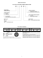
Model Description . . . . . . . . . . . . . . . . . . . . . . . . . . . . . . . . . 3
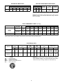
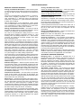
ARI Capacity Ratings . . . . . . . . . . . . . . . . . . . . . . . . . . . . . . 3
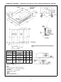
Dimensional Drawings . . . . . . . . . . . . . . . . . . . . . . . . . . . . . 4-6
Specifications . . . . . . . . . . . . . . . . . . . . . . . . . . . . . . . . . . . . 7
Selection Procedure . . . . . . . . . . . . . . . . . . . . . . . . . . . . . . . 8
Gross Cooling Capacities . . . . . . . . . . . . . . . . . . . . . . . . . . . 9
Integrated Heating Capacities . . . . . . . . . . . . . . . . . . . . . . . 9
Air Delivery . . . . . . . . . . . . . . . . . . . . . . . . . . . . . . . . . . . . . 10
Electric Resistance Heater Data . . . . . . . . . . . . . . . . . . . . . 11
Electrical Data . . . . . . . . . . . . . . . . . . . . . . . . . . . . . . . . . . . 11
Operating Sequence . . . . . . . . . . . . . . . . . . . . . . . . . . . . . . 12
Application Data . . . . . . . . . . . . . . . . . . . . . . . . . . . . . . . . . 13
Typical Field Wiring . . . . . . . . . . . . . . . . . . . . . . . . . . . . . 14,15
Typical Installation . . . . . . . . . . . . . . . . . . . . . . . . . . . . . . . . 15
Engineers’ Specification Guide . . . . . . . . . . . . . . . . . . . . . . 16
2