1
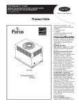
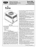
48HC
High Efficiency
Gas Heat/Electric Cooling Packaged Rooftop
15 to 25 Nominal Tons
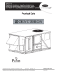
Product Data
C10997
(Unit shown with economizer and power exhaust.)
the environmentally sound refrigerant
TABLE OF CONTENTS
PAGE
PAGE
FEATURES AND BENEFITS . . . . . . . . . . . . . . . . . . . . 3
APPLICATION/SELECTION DATA . . . . . . . . . . . . . . 24
MODEL NUMBER NOMENCLATURE . . . . . . . . . . . . 4
COOLING CAPACITIES . . . . . . . . . . . . . . . . . . . . . . . 26
FACTORY OPTIONS AND/OR ACCESSORIES . . . . . 6
STATIC PRESSURE ADDERS . . . . . . . . . . . . . . . . . . 34
AHRI COOLING RATING TABLES . . . . . . . . . . . . . . . 9
DAMPER, BARO RELIEF & PE PERFORMANCE . 35
HEAT RATING TABLE . . . . . . . . . . . . . . . . . . . . . . . . . 9
FAN PERFORMANCE . . . . . . . . . . . . . . . . . . . . . . . . . 37
SOUND PERFORMANCE TABLE . . . . . . . . . . . . . . . 10
ELECTRICAL INFORMATION . . . . . . . . . . . . . . . . . 42
PHYSICAL DATA . . . . . . . . . . . . . . . . . . . . . . . . . . . . . 11
SEQUENCE OF OPERATION . . . . . . . . . . . . . . . . . . . 57
DIMENSIONS . . . . . . . . . . . . . . . . . . . . . . . . . . . . . . . . 14
GUIDE SPECIFICATIONS . . . . . . . . . . . . . . . . . . . . . . 60
OPTIONS & ACCESSORIES WEIGHT ADDERS . . . 23
Your new 15 to 25 Ton WeatherMaster Carrier rooftop unit (RTU) was designed by customers for customers. With a newly
designed cabinet that integrates “no-- strip” screw collars, handled access panels, and more we’ve made your unit easy to
install, easy to maintain, easy to use and reliable.
Easy to install:
These new WeatherMaster units are designed for dedicated factory-- supplied vertical or horizontal air flow duct
configurations. No special field kits are required. Designed to fit on pre-- installed curbs by another manufacturer, these
units also fit on past designed Carrier installed curbs with a new certified and authorized adapter curb. This new cabinet
design also integrates a large control box that gives you room to work and room to mount Carrier accessory controls.
Easy to maintain:
Easy access handles by Carrier provide quick and easy access to all normally serviced components. Our “no-- strip” screw
system has superior holding power and guides screws into position while preventing the screw from stripping the unit’s
metal. Take accurate pressure readings by reading system pressures with panels in place as compressors are strategically
located to eliminate any air bypass.
Easy to use:
The newly designed, central terminal board by Carrier puts all your connections and troubleshooting points in one
convenient place, standard. Most low voltage connections are made to the same board and make it easy to find what you’re
looking for and easy to access it.
Reliable:
Each unit comes with precision sized and tested scroll compressor that is internally protected from over temperature and
pressures. In addition, each refrigerant circuit is further protected with a high pressure and low pressure switch as well as
containing a liquid line filter drier. Each unit is factory tested prior to shipment to help ensure unit operation once properly
installed.
2
FEATURES AND BENEFITS
S Two stage cooling capability with independent circuits and control.
S High performance copper tube / aluminum plate (RTPF) fin condenser and evaporator coils with optional coating.
S EER’s up to 12.0
S IEER’s up to 13.2 with single speed indoor fan motor and 13.8 with SAVt (Staged Air Volume) 2-- speed/VFD indoor
fan motor
S Gas heating efficiencies up to 81% thermal efficiency.
S Dedicated vertical and horizontal air flow duct configuration models. No field kits required.
S Utility connections through the side or bottom. Bottom connections are also in an enclosed environment to help prevent
water entry. Field supplied couplings are required.
S Standardized components and layout. Standardized components and controls make service and stocking parts easier.
S Scroll compressors on all units. This makes service, stocking parts, replacement, and trouble-- shooting easier.
S Precision sized TXV metering device on each refrigerant circuit.
S Easy-- adjust, belt-- drive motor available. Motor assembly also contains a fan belt break protection system on all models
and reliable pillow block bearing system that allows lubrication thru front of the unit.
S Single-- point gas / electrical connection.
S Sloped, composite drain pan sheds water; and won’t rust.
S Standardized controls and control box layout. Standardized components and controls make stocking parts and service
easier.
S Clean, large, easy to use control box.
S Color-- coded wiring.
S Large, laminated wiring and power wiring drawings which are affixed to unit make troubleshooting easy.
S Single, central terminal board for test and wiring connections.
S Fast-- access, handled, panels for easy access on normally accessed service panels.
S “No-- strip” screw system guides screws into the panel and captures them tightly without stripping the screw, the panel, or
the unit.
S Mechanical cooling (125_F to 35_F / 52_C to - 2_C) standard on all models. Low ambient controller allows operation
down to - 20_F / - 29_C
S Redundant gas valve for 2-- stage gas heating capacity control with induced-- draft flue exhaust design to help ensure no
flue gas can escape into the indoor air stream.
S Exclusive IGC solid state gas controller for on board diagnostics with LED error code designation, burner control logic
and energy saving indoor fan motor delay.
S 2-- in (51mm) disposable filters on all units, with 4-- in (102mm) filter track field-- installed.
S Refrigerant filter-- drier on each circuit.
S High and low pressure switches. Added reliability with high pressure switch and low pressure switch.
S Many factory-- installed options ranging from air management economizers, 2 position dampers, manual outdoor air
dampers, plus convenience outlets, disconnect switch and smoke detectors.
S Factory-- installed Humidi-- MiZerr Adaptive Dehumidification System.
S Standard Parts Warranty: 10 year aluminized heat exchanger, 5 year compressor, 1 year others.
S Optional Staged Air Volume (SAV) system utilizes a Variable Frequency Drive (VFD) to automatically adjust the indoor
fan motor speed between cooling stages. Available on models with electromechanical, ComfortLink or RTU Open
controls.
3
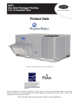
MODEL NUMBER NOMENCLATURE
1
4
2
8
3
4
5
6
H C D D
7
2
8
4
9
A
10 11 12 13 14 15 16 17 18
3
A
5
---
0
A
0
Product Type
48 --- Gas Heat Pkg. Rooftop
A
0
Packaging
0 --- Standard
Model Series --- WeatherMaster
HC --- High Efficiency
Electrical Options
A --- None
B --- HACR breaker
C --- Non--- fused disconnect
G --- 2--- speed indoor fan (VFD) controller
J --- 2--- spd contr (VFD) & non--- fused disc.
Heat Size
D --- Low Gas Heat
E --- Medium Gas Heat
F --- High Gas Heat
S --- Low Heat w/Stainless Steel Exchanger
R = Med Heat w/Stainless Steel Exchanger
T --- High Heat w/Stainless Steel Exchanger
Service Options
0 --- None
1 --- Un--- powered Convenience Outlet
2 --- Powered Convenience Outlet
3 --- Hinged Panels
4 --- Hinged Panels, un--- powered C.O.
5 --- Hinged Panels, powered C.O.
C --- Foil faced insulation
Refrigerant System Options
D --- 2 stage Cooling
E --- 2 stg cooling w/Humidi--- MiZer
G --- 2 stg cool w/Motormaster low amb cntl
Nominal Cooling Capacity (Tons)
17 --- 15 tons
20 --- 17.5 tons
24 --- 20 tons
28 --- 25 tons
Intake / Exhaust Options
A --- None
B --- Temperature Economizer w/Barometric Relief
F --- Enthalpy Economizer w/Barometric Relief
K --- 2 position Damper
U --- Temp Ultra Low Leak Economizer w/Baro Relief
W --- Enthalpy Ultra Low Leak Econo w/Baro Relief
X --- Enthalpy Ultra Low Leak Econ w/P (cent)--Vertical Air Only
Sensor Options
A --- None
B --- RA Smoke Detector
C --- SA Smoke Detector
D --- RA + SA Smoke Detector
E --- CO2 Sensor
F --- RA Smoke Detector + CO2
G --- SA Smoke Detector + CO2
H --- RA + SA Smoke Detector + CO2
Base Unit Controls
0 --- Base Electromechanical Controls
1 --- PremierLink Controller
2 --- RTU Open Multi--- Protocol Controller
6 --- Electromechanical with 2 speed fan and W7220
Econo controller
D --- ComfortLink Controls
Indoor Fan Options & Air Flow Configuration
1 --- Standard Static / Vertical Supply, Return Air Flow
2 --- Medium Static / Vertical Supply, Return Air Flow
3 --- High Static / Vertical Supply, Return Air Flow
B --- Med Static High Eff Motor / Vert Supply, Return Air Flow
C = High Static High Eff Motor / Vert Supply, Return Air Flow
2 --- Medium Static Option --- Belt Drive
5 --- Standard Static / Horizontal Supply, Return Air Flow
6 --- Medium Static / Horizontal Supply, Return Air Flow
7 --- High Static / Horizontal Supply, Return Air Flow
F --- Med Static Hi Eff Motor / Horizontal Supply, Return Air Flow
G --- High Static High Eff Motor / Horiz Supply, Return Air Flow
Design Revision
--- Factory Design Revision
Voltage
1 --- 575/3/60
5 --- 208--- 230/3/60
6 --- 460/3/60
Coil Options (RTPF) (Outdoor ---Indoor ---Hail Guard)
A --- Al/Cu --- Al/Cu
B --- Pre--- coat Al/Cu --- Al/Cu
C --- E--- coat Al/Cu --- Al/Cu
D --- E--- coat AL/Cu --- E--- coat AL/Cu
E --- Cu/Cu --- Al/Cu
F --- Cu/Cu --- Cu/Cu
M --- Al/Cu --- Al/Cu --- Louvered Hail Guard
N --- Pre--- Coat Al/Cu --- Al/Cu --- Louvered Hail Guard
P --- E--- Coat Al/Cu --- Al/Cu Louvered Hail Guard
Q --- E---Coat Al/Cu --- E---coat Al/Cu --- Louvered Hail Guard
R --- Cu/Cu --- Al/Cu --- Louvered Hail Guard
S --- Cu/Cu --- Cu/Cu --- Louvered Hail Guard
Not all possible options can be displayed above --- see following pages for more details
4
Table 1 – FACTORY-- INSTALLED OPTIONS AND FIELD-- INSTALLED ACCESSORIES
CATEGORY
Cabinet
Coil Options
Humidity Control
Condenser Protection
Controls
Economizers
& Outdoor Air
Dampers
Economizer Sensors
&
IAQ Devices
Gas Heat
Indoor Motor
& Drive
Low Ambient
Control
Power
Options
Roof Curbs
ITEM
Dedicated Vertical Air Flow Duct Configuration
Dedicated Horizontal Air Flow Duct Configuration
Hinged Access Panels
Foil faced insulation throughout entire cabinet
Cu/Cu (indoor) coils
E ---coated (outdoor & indoor) coils
Pre ---coated outdoor coils
Humidi ---MiZer Adaptive Dehumidification System
Condenser coil hail guard (louvered design)
Thermostats, temperature sensors, and subbases
PremierLink DDC communicating controller
ComfortLink Controls
RTU Open protocol controller
Smoke detector (supply and/or return air)
Time Guard II compressor delay control circuit
Phase Monitor
EconoMi$ert IV (for electro---mechanical controlled RTUs)
EconoMi$ert2 (for DDC controlled RTUs)
Motorized 2 position outdoor ---air damper
Manual outdoor ---air damper (25%)
Barometric relief1
Barometric hood (Horizontal economizer)
Power exhaust–centrifugal blower
Ultra Low Leak EconoMi$er X (for 2---speed SAV system only 17 to
28 sizes with 2 stages of cooling), vertical supply and return air only.
Single dry bulb temperature sensors2
Differential dry bulb temperature sensors2
Single enthalpy sensors2
Differential enthalpy sensors2
Wall or duct mounted CO2 sensor2
Unit mounted CO2 sensor2
4---in Filter Track Assembly
Propane conversion kit
Stainless steel heat exchanger
High altitude conversion kit
Flue Discharge Deflector
Multiple motor and drive packages
Staged Air Vol (SAV) system w/VFD controller (2---stage cool only
with electrical mechanical and RTU Open controls)
Display Kit for SAV system with VFD
Winter start kit3
Motormaster head pressure controller to ---20_F (---29_C)3
Cooling Low Ambient Controller to 0_F (---18_C)3
Convenience outlet (powered)
Convenience outlet (unpowered)
HACR circuit breaker4
Non ---fused disconnect5
Roof curb 14---in (356mm)
Roof curb 24---in (610mm)
Adapter Curb (Adapts to Models – DP/DR/HJ/TM/TJ)6
FACTORY
INSTALLED
OPTION
X
X
X
X
X
X
X
X
X
X
X
X
X
FIELD
INSTALLED
ACCESSORY
X
X
X
X
X
X
X
X
X
X
X
X
X
X
X
X
X
X
X
X
X
X
X
X
X
X
X
X
X
X
X
X
X
X
X
X
X
X
X
X
X
X
X
X
X
X
X
NOTES:
1. Included with economizer.
2. Sensors used to optimize economizer performance.
3. See application data for assistance.
4. HACR circuit breaker cannot be used when rooftop MOCP electrical rating exceeds 200 amps at 208/230 volt, 90 amps at 460 volt and
90 amps at 575 volt. 575 volt can only be used on Wye power supply. Delta power supply is prohibited. Carrier RTUBuilder selects this
automatically.
5. Non--- fused disconnect switch cannot be used when FLA electrical rating exceeds 200 amps at 460/575 volt and 200 amps at 208/230
volt. Carrier Packaged RTUBuilder selects this automatically.
6. Not for 48TJE024--- 028 models using 48DP900041, 48DP900051 or 48DP900061 roofcurbs.
5
FACTORY OPTIONS AND/OR ACCESSORIES
Economizer (dry--bulb or enthalpy)
Power Exhaust with Barometric Relief
Economizers save money. They bring in fresh, outside air
for ventilation; and provide cool, outside air to cool your
building. This is the preferred method of low-- ambient
cooling. When coupled to CO2 sensors, economizers can
provide even more savings by coupling the ventilation air
to only that amount required.
Superior internal building pressure control. This
field-- installed accessory or factory-- installed option may
eliminate the need for costly, external pressure control
fans.
Economizers are available, installed and tested by the
factory, with either enthalpy or dry-- bulb temperature
inputs. There are also models for electromechanical as
well as direct digital controllers. Additional sensors are
available as accessories to optimize the economizers.
This CCN controller regulates your rooftop’s performance
to tighter tolerances and expanded limits, as well as
facilitates zoning systems and digital accessories. It also
unites your Carrier HVAC equipment together on one,
coherent CCN network. The PremierLink can be
factory-- installed, or easily field-- installed.
Economizers include gravity controlled, barometric relief
equalizes building pressure and ambient air pressures.
This can be a cast effective solution to prevent building
pressurization. If further control of exhaust air is required,
a dual centrifugal fan power exhaust system is also
available.
CO2 Sensor
Improves productivity and saves money by working with
the economizer to intake only the correct amount of
outside air for ventilation. As occupants fill your building,
the CO2 sensor detects their presence through increasing
CO2 levels, and opens the economizer appropriately.
When the occupants leave, the CO2 levels decrease, and
the sensor appropriately closes the economizer. This
intelligent control of the ventilation air, called Demand
Control Ventilation (DCV) reduces the overall load on the
rooftop, saving money.
Smoke Detectors
Trust the experts. Smoke detectors make your application
safer and your job easier. Carrier smoke detectors
immediately shut down the rooftop unit when smoke is
detected. They are available, installed by the factory, for
supply air, return air, or both.
Louvered Hail Guards
Sleek, louvered panels protect the condenser coil from
hail damage, foreign objects, and incidental contact.
Convenience Outlet (powered or un--powered)
Reduce service and/or installation costs by including a
convenience outlet in your specification. Carrier will
install this service feature at our factory. Provides a
convenient, 15 amp, 115v GFCI receptacle with “Wet in
Use” cover. The “powered” option allows the installer to
power the outlet from the line side of the disconnect side
as required by code. The “unpowered” option is to be
powered from a separate 115/120v power source.
Non--Fused Disconnect
This OSHA-- compliant, factory-- installed, safety switch
allows a service technician to locally secure power to the
rooftop.
PremierLink, DDC Controller
RTU Open Protocol Controller
Connect the rooftop to an existing BAS without needing
complicated translators or adapter modules using the RTU
Open controller. This new controller speaks the 4 most
common building automation system languages (Bacnet,
Modbus, N2, and Lonworks). Use this controller when
you have an existing BAS.
Time Guard II Control Circuit
This accessory protects your compressor by preventing
short-- cycling in the event of some other failure, prevents
the compressor from restarting for 30 seconds after
stopping. Not required with PremierLink, RTU Open, or
authorized commercial thermostats.
Motorized 2--Position Damper
The new Carrier 2-- position, motorized outdoor air damper
admits up to 100% outside air. Using reliable, gear-- driven
technology, the 2-- position damper opens to allow
ventilation air and closes when the rooftop stops, stopping
unwanted infiltration.
Manual OA Damper
Manual outdoor air dampers are an economical way to
bring in ventilation air. The dampers are available in 25%
versions.
Optional Humidi--MiZer Adaptive
Dehumidification System
Carrier’s Humidi-- MiZer adaptive dehumidification
system is an all-- inclusive factory installed option that can
be ordered with any WeatherMaster 48HC17-- 28 rooftop
unit.
This system expands the envelope of operation of
Carrier’s WeatherMaster rooftop products to provide
unprecedented flexibility to meet year round comfort
conditions.
The Humidi-- MiZer adaptive dehumidification system has
the industry’s only dual dehumidification mode setting.
The Humidi-- MiZer system includes two new modes of
operation.
6
FACTORY OPTIONS AND/OR ACCESSORIES (cont.)
Opt. Humidi--MiZer Adap. Dehum. Syst. (cont.)
The WeatherMaster 48HC17-- 28 rooftop coupled with the
Humidi-- MiZer system is capable of operating in normal
design cooling mode, subcooling mode, and hot gas reheat
mode. Normal design cooling mode is when the unit will
operate under its normal sequence of operation by cycling
compressors to maintain comfort conditions.
Subcooling mode will operate to satisfy part load type
conditions when the space requires combined sensible and
a higher proportion of latent load control. Hot Gas Reheat
mode will operate when outdoor temperatures diminish
and the need for latent capacity is required for sole
humidity control. Hot Gas Reheat mode will provide
neutral air for maximum dehumidification operation.
Staged Air Volume (SAV) Indoor Fan Speed
System
Carrier’s Staged Air Volume (SAV) system saves energy
and installation time by utilizing a Variable Frequency
Drive (VFD) to automatically adjust the indoor fan motor
speed in sequence with the units cooling operation. Per
ASHRAE 90.1 2010 standard section 6.4.3.10.b, during
the first stage of cooling operation the VFD will adjust the
fan motor to provide 2/3rd of the total cfm established for
the unit. When a call for the second stage of cooling is
required, the VFD will allow the total cfm for the unit
established (100%). During the heating mode the VFD
will allow total design cfm (100%) operation and during
the ventilation mode the VFD will allow operation to
2/3rd of total cfm.
Compared to single speed indoor fan motor systems,
Carrier’s SAV system can save substantial energy, 25%+*,
versus single speed indoor fan motor systems.
The VFD used in Carrier’s SAV system has soft start
capabilities to slowly ramp up the speeds, thus eliminating
any high inrush air volume during initial start-- up. It also
has internal over current protection for the fan motor and
a field installed display kit that allows adjustment and in
depth diagnostics of the VFD.
This SAV system is available on models with 2-- stage
cooling operation with electrical mechanical or RTU
Open, Multi Protocol controls. Both space sensor and
conventional thermostats controls can be used to provide
accurate control in any application.
The SAV system is very flexible for initial fan
performance set up and adjustment. The standard factory
shipped VFD is pre-- programmed to automatically stage
the fan speed between the first and second stage of
cooling. The unit fan performance static pressure and cfm
can be easily adjusted using the traditional means of
pulley adjustments. The other means to adjust the unit
static and cfm performance is to utilize the field installed
Display Kit and adjust the frequency and voltage in the
VFD to required performance requirements. In either case,
once set up, the VFD will automatically adjust the speed
between the cooling stage operations.
*Data based on .10 ($/kWh) in an office application
utilizing Carrier’s HAP 4.6 simulation software program.
MotorMaster Head Pressure Controller
The MotorMaster motor controller is a low ambient, head
pressure controller kit that is designed to maintain the
unit’s condenser head pressure during periods of low
ambient cooling operation. This device should be used as
an alternative to economizer free cooling not when
economizer usage is either not appropriate or desired. The
Motormaster will either cycle the outdoor-- fan motors or
operate them at reduced speed to maintain the unit
operation, depending on the model.
MotorMaster allows cooling operation down to - 20_F
(-- 29_C) ambient conditions.
Winter Start Kit
The winter start kit by Carrier extends the low ambient
limit of your rooftop to 25_F (-- 4_C). The kit bypasses the
low pressure switch, preventing nuisance tripping of the
low pressure switch. Other low ambient precautions may
still be prudent.
Propane Heating
Convert your gas heat rooftop from standard natural gas
operation to Propane using this field-- installed kit.
High Altitude Heating
High altitudes have less oxygen, which means heat
exchangers need less fuel. The new gas orifices in this
field-- installed kit make the necessary adjustment for high
altitude applications. They restore the optimal fuel to air
mixture and maintain healthy combustion at altitudes
above 2000 ft (610m). Kits may not be required in all
areas.
Optional Stainless Steel Heat Exchanger
The stainless steel heat exchanger option provides the
tubular heat exchanger be made out of a minimum 20
gauge type 409 stainless steel for applications where the
mixed air to the heat exchanger is expected to drop below
45_F (7_C). Stainless steel may be specified on
applications where the presence of airborne contaminants
require its use (applications such as paper mills) or in area
with very high outdoor humidity that may result in severe
condensation in the heat exchanger during cooling
operation.
Flue Discharge Deflector
The flue discharge deflector is a useful accessory when
flue gas recirculation is a concern. By venting the flue
discharge upwards, the deflector minimizes the chance for
a neighboring unit to intake the flue exhaust.
7
FACTORY OPTIONS AND/OR ACCESSORIES (cont.)
Alternate Motors and Drives
Some applications need larger horsepower motors, some
need more airflow, and some need both. Regardless of the
case, your Carrier expert has a factory installed
combination to meet your application. A wide selection of
motors and pulleys (drives) are available, factory
installed, to handle nearly any application.
Thru--the--Base Connections
Thru-- the-- base provisions/connection points are available
as standard with every unit. When bottom connections are
required, field furnished couplings are required.
Barometric Hood
For Horizontal Economizer applications where relief
damper is installed in duct work. This kit provides the
needed protection.
Hinged Access Panels
Allows access to unit’s major components with
specifically designed hinged access panels. Panels are
filter, control box, indoor fan motor.
ComfortLink Controls
Models with the optional Carrier ComfortLink Controls
allow added unit diagnostics and operation setup
capabilities, as well as controlling logic for single zone
Variable Air Volume (VAV) applications.
The ComfortLink control is your link to a world of simple
and easy to use rooftop units that offer outstanding
performance and value. It optimizes the performance of
the refrigeration circuits as conditions change, resulting in
the following features:
—
—
—
—
—
Better control of temperature and humidity
Superior reliability
Automatic redundancy
Low ambient cooling operation to 0_F (-- 18_C)
More accurate diagnostics, at unit or remote
The ComfortLink Scrolling Marquee is very easy to use.
The messages are displayed in easy to understand English,
no decoding is required. A scrolling readout provides
detailed explanations of control information. Only four,
large, easy-- to-- use buttons are required to maneuver
through the entire menu. The readout is designed to be
visible even in the brightest sunlight. A handheld
Navigator accessory or wall-- mounted System Pilott
accessory can be used for added service flexibility.
The ComfortLink control provides unparalleled service
diagnostic information. Temperature and pressure can be
read directly from the display with no need for separate
gauges. Other data, such as compressor cycles, unit run
time hours, current alarms, can also be accessed. A history
of alarms is also available for viewing.
The service run test can be very helpful when
troubleshooting. The user can run test major components
to determine the root cause of a problem. The unit can be
run-- tested before an installation is complete to ensure
satisfactory start-- up. To ensure reliability, the
ComfortLink control prevents reverse compressor
rotation. No laptop computers are required for start-- up.
Time schedules are built in and the Scrolling Marquee
display provides easy access to setpoints. The
ComfortLink control accepts input from a CO2 sensor and
a smoke detector. Both are available as factory installed
options or as field installed accessories.
HACR Breaker
These manual reset devices provide overload and short
circuit protection for the unit. Factory wired and mounted
with the units with access cover to help provide
environment protection.
On 575V applications, HACR breaker can only be used
with WYE power distribution systems. Use on Delta
power distribution systems is prohibited.
Foil Faced Insulated Cabinet
Cabinet is fully insulated with non-- fibrous, foil faced
cleanable insulation that is secured and encapsulated in
unit design.
Low Ambient Controller
The low ambient controller is a head pressure controller
kit that is designed to maintain the unit’s condenser head
pressure during periods of low ambient cooling operation.
This device should be used as an alternative to
economizer free cooling not when economizer usage is
either not appropriate or desired. The low ambient
controller will either cycle the outdoor fan motors or
operate them at reduced speed to maintain the unit
operation, depending on the model. This controller allows
cooling operation down to 0_F (-- 18_C) ambient
conditions.
8
Table 2 – AHRI COOLING RATING TABLE 2-- STAGE COOLING
UNIT
COOLING
STAGES
NOM.
CAPACITY
(TONS)
17
20
24
28
2
2
2
2
15
18
20
25
LEGEND
AHRI
ASHRAE
EER
IEER
NET
COOLING
CAPACITY
(MBH)
174.0
202.0
236.0
282.0
TOTAL
POWER (kW)
EER
IEER WITH
SINGLE SPEED
INDOOR FAN
IEER WITH
2---SPEED
INDOOR FAN
14.5
16.8
19.7
25.2
12.0
12.0
12.0
11.2
13.0
13.0
13.2
12.0
13.5
13.6
13.8
12.5
NOTES:
1. Rated and certified under AHRI Standard 340/360, as appropriate.
2. Ratings are based on:
Cooling Standard: 80_F (27_C) db, 67_F (19_C) wb indoor
air temp and 95_F (35_C) db outdoor air temp.
IEER Standard: A measure that expresses cooling part--- load
EER efficiency for commercial unitary air conditioning and
heat pump equipment on the basis of weighted operation at
various load capacities.
3. All 48HC units comply with ASHRAE 90.1 and Energy Star
Energy Standard for minimum EER and IEER requirements.
4. 48HC units comply with US Energy Policy Act (2005). To evaluate code compliance requirements, refer to state and local
codes or visit the following website: http://bcap --- energy.org
to determine if compliance with this standard pertains to your
state, territory, or municipality.
--- Air Conditioning, Heating and Refrigeration
Institute Test Standard
--- American Society of Heating, Refrigerating
and Air Conditioning, Inc.
--- Energy Efficiency Ratio
--- Integrated Energy Efficiency Ratio
Use of the AHRI Certified
TM Mark indicates a
manufacturer’s
participation in the
program For verification
of certification for individual
products, go to
www.ahridirectory.org.
Table 3 – HEATING RATING TABLE - NATURAL GAS & PROPANE
MODEL
SIZE
17
20
24
28
HEAT
SIZE
LOW
MED
HIGH
LOW
MED
HIGH
LOW
MED
HIGH
LOW
MED
HIGH
AL/SS HEAT EXCHANGER
INPUT / OUTPUT
STAGE 1 (MBH)
176 / 142
248 / 200
320 / 260
176 / 142
248 / 200
320 / 260
176 / 142
248 / 200
320 / 260
176 / 142
248 / 200
320 / 260
INPUT / OUTPUT
STAGE 2 (MBH)
220 / 178
310 / 251
400 / 324
220 / 178
310 / 251
400 / 324
220 / 178
310 / 251
400 / 324
220 / 178
310 / 251
400 / 324
TEMP RISE
(DEG F)
THERMAL
EFFICIENCY
(%)
20 --- 55
30 --- 60
35 --- 65
15 --- 55
25 --- 60
30--- 65
15 --- 55
20 --- 60
30--- 65
10 --- 55
15 --- 60
20 --- 65
81%
81%
81%
81%
81%
81%
81%
81%
81%
81%
81%
81%
NOTES:
Heat ratings are for natural gas heat exchangers operated at or below 2000 ft (610 m). For information on Propane or altitudes above 2000
ft (610 m), see the Application Data section of this book. Accessory Propane/High Altitude kits are also available.
In the USA the input rating for altitudes above 2000 ft (610m) must be derated by 4% for each 1000 ft (305 m) above sea level. In Canada,
the input rating must be derated by 10% for altitudes of 2000 ft (610 m) to 4500 ft (1372 m) above sea level.
9
Table 4 – SOUND PERFORMANCE TABLE
Outdoor Sound (dB)
MODEL
SIZE
COOLING
STAGES
17
20
24
28
2
2
2
2
A ---Wtg.
AHRI
370
Rating
63
125
250
500
1000
2000
4000
8000
84.1
84.1
86.5
85.9
84
84
87
86
92.2
92.2
95.6
97.1
83.9
83.9
87.5
88.3
80.4
80.4
84.2
84.4
81.8
81.8
84.2
83.3
78.7
78.7
81.7
80.7
76.5
76.5
77.9
77.4
72.2
72.2
73.2
73.4
65.4
65.4
66.3
67.3
LEGEND
dB --- Decibel
NOTES:
1. Outdoor sound data is measure in accordance with AHRI
standard 270--- 2008.
2. Measurements are expressed in terms of sound power. Do
not compare these values to sound pressure values because
sound pressure depends on specific environmental factors
which normally do not match individual applications. Sound
power values are independent of the environment and therefore more accurate.
3. A--- weighted sound ratings filter out very high and very low
frequencies, to better approximate the response of “average”
human ear. A--- weighted measurements for Carrier units are
taken in accordance with AHRI standard 270--- 2008.
Table 5 – MINIMUM - MAXIMUM AIRFLOW RATINGS - NATURAL GAS & PROPANE
COOLING
MODEL
SIZE
HEAT
SIZE
Minimum
Single
Speed
Fan Motor
LOW
MED
4500
HIGH
LOW
MED
20
5250
HIGH
LOW
MED
24
6000
HIGH
LOW
MED
28
7500
HIGH
AL = Aluminum Gas Heat Exchanger
SS = Stainless Steel Gas Heat Exchanger
17
Minimum
2---speed
Fan Motor
(at high
speed)
Minimum
2---speed
Fan Motor
(at low
speed)
Maximum
5070
3346
7500
5915
3904
9000
7500
4950
10000
8450
5577
12500
10
AL HEAT EXCHANGER
HEATING
SS HEAT EXCHANGER
HEATING
Minimum
Maximum
Minimum
Maximum
3000
3880
4620
3000
3880
4620
3000
3880
4620
3000
3880
4620
8250
7750
8570
11000
9300
10000
11000
11630
10000
16500
15500
15000
3000
3880
4620
2960
3880
4620
3000
3880
4620
2960
3880
4620
8250
7750
8570
11000
9300
10000
11000
11630
10000
16500
15500
15000
48HC*17
48HC*20
48HC*24
48HC*28
2 / 2 / Scroll
17/16.4
24.5/25.7
TXV
630 / 505
54 / 117
27 / 44
50% / 100%
2 / 2 / Scroll
17.5/16.8
25.5/25.5
TXV
630 / 505
54 / 117
27 / 44
50% / 100%
2 / 2 / Scroll
23.8/23.1
30.0/30.7
TXV
630 / 505
54 / 117
27 / 44
50% / 100%
2 / 2 / Scroll
24.9/27.7
35.1/35.4
TXV
630 / 505
54 / 117
27 / 44
50% / 100%
Cu / Al
3/8--- in RTPF
4 / 15
22
3/4--- in
Cu / Al
3/8--- in RTPF
4 / 15
22
3/4--- in
Cu / Al
3/8--- in RTPF
4 / 15
26
3/4--- in
Cu / Al
3/8--- in RTPF
4 / 15
26
3/4--- in
Cu / Al
3/8--- in RTPF
1 / 17
22
Cu / Al
3/8--- in RTPF
1 / 17
22
Cu / Al
3/8--- in RTPF
1 / 17
26
Cu / Al
3/8--- in RTPF
1 / 17
26
Standard Static
15 - 25 TONS
Motor Qty / Drive type
Max BHP
RPM range
Motor frame size
Fan Qty / Type
Fan Diameter (in)
1 / Belt
2.2
514--- 680
56
2 / Centrifugal
15 x 15
1 / Belt
3.3
622--- 822
56
2 / Centrifugal
15 x 15
1 / Belt
4.9
690--- 863
56
2 / Centrifugal
15 x 15
1 / Belt
4.9
717--- 911
56
2 / Centrifugal
15 x 15
Medium Static
(COOLING)
Motor Qty / Drive type
Max BHP
RPM range
Motor frame size
Fan Qty / Type
Fan Diameter (in)
1 / Belt
3.3
679--- 863
56
2 / Centrifugal
15 x 15
1 / Belt
4.9
713--- 879
56
2 / Centrifugal
15 x 15
1 / Belt
6.5
835--- 1021
184T
2 / Centrifugal
15 x 15
1 / Belt
6.5
913--- 1116
184T
2 / Centrifugal
15 x 15
High Static
Table 6 – PHYSICAL DATA
Motor Qty / Drive type
Max BHP
RPM range
Motor frame size
Fan Qty / Type
Fan Diameter (in)
1 / Belt
4.9
826--- 1009
56
2 / Centrifugal
15 x 15
1 / Belt
6.5
882--- 1078
184T
2 / Centrifugal
15 x 15
1 / Belt
8.7
941--- 1176
213T
2 / Centrifugal
15 x 15
1 / Belt
8.7
941--- 1176
213T
2 / Centrifugal
15 x 15
Refrigeration System
# Circuits / # Comp. / Type
R--- 410a charge A/B (lbs)
Humidi--- MiZer R--- 410a charge A/B (lbs)
Metering device
High--- press. Trip / Reset (psig)
Low--- press. Trip / Reset (psig)
Humidi--- MiZer Low--- press. Trip / Reset (psig)
Compressor Capacity Staging (%)
Evap. Coil
Material
Tube Diameter
Rows / FPI
Total face area (ft2)
Condensate drain conn. size
Humidi---MiZer Coil
Material
Tube Diameter
Rows / FPI
Total face area (ft2)
Evap. fan and motor
VERTICAL
11
48HC*17
48HC*20
48HC*24
48HC*28
Standard Static
15 - 25 TONS
Motor Qty / Drive type
Max BHP
RPM range
Motor frame size
Fan Qty / Type
Fan Diameter (in)
1 / Belt
2.2
514--- 680
56
2 / Centrifugal
18 x 15/15 X 11
1 / Belt
3.3
622--- 822
56
2 / Centrifugal
18 x 15/15 X 11
1 / Belt
4.9
690--- 863
56
2 / Centrifugal
18 x 15/15 X 11
1 / Belt
4.9
647--- 791
184T
2 / Centrifugal
18 x 15/15 X 11
Medium Static
(COOLING)
Motor Qty / Drive type
Max BHP
RPM range
Motor frame size
Fan Qty / Type
Fan Diameter (in)
1 / Belt
3.3
614--- 780
56
2 / Centrifugal
18 x 15/15 X 11
1 / Belt
4.9
713--- 879
56
2 / Centrifugal
18 x 15/15 X 11
1 / Belt
6.5
835--- 1021
184T
2 / Centrifugal
18 x 15/15 X 11
1 / Belt
6.5
755--- 923
184T
2 / Centrifugal
18 x 15/15 X 11
High Static
Table 6 – PHYSICAL DATA (cont.)
Motor Qty / Drive type
Max BHP
RPM range
Motor frame size
Fan Qty / Type
Fan Diameter (in)
1 / Belt
4.9
746--- 912
56
2 / Centrifugal
18 x 15/15 X 11
1 / Belt
6.5
882--- 1078
184T
2 / Centrifugal
18 x 15/15 X 11
1 / Belt
8.7
941--- 1176
213T
2 / Centrifugal
18 x 15/15 X 11
1 / Belt
8.7
827--- 1010
213T
2 / Centrifugal
18 x 15/15 X 11
RTPF
70
44
2 /17
21.4
RTPF
72
44
2 /17
22.0
RTPF
82
52
2 /17
29.6
RTPF
95
52
2 /17
34.3
RTPF
70
44
2 /17
21.4
RTPF
64
44
2 /17
19.5
RTPF
80
52
2 /17
29.6
RTPF
95
52
2 /17
34.3
3 / direct
1/4 / 1100
22
4 / direct
1/4 / 1100
22
4/ direct
1/4 / 1100
22
6 / direct
1/4 / 1100
22
6 / 20 x 25 x 2
4 / 16 x 25 x 1
6 / 20 x 25 x 2
4 / 16 x 25 x 1
9 / 16 x 25 x 2
4 / 16 x 25 x 1
9 / 16 x 25 x 2
4 / 16 x 25 x 1
HORIZONTAL
Cond. Coil (Circuit A)
Coil type
Coil Length (in)
Coil Height (in)
Rows / FPI (fins per inch)
Total face area (ft2)
Cond. Coil (Circuit B)
Coil type
Coil Length (in)
Coil Height (in)
Rows / FPI (fins per inch)
Total face area (ft2)
Cond. fan / motor
Qty / Motor drive type
Motor HP / RPM
Fan diameter (in)
Filters
RA Filter # / size (in)
OA inlet screen # / size (in)
12
Table 7 – PHYSICAL DATA
(HEATING)
15 - 25 TONS
48HC*D17
48HC*D20
48HC*D24
48HC*D28
# of Gas Valves
Nat. gas supply line press (in. w.g.)/(PSIG)
Propane supply line press (in. w.g.)/(PSIG)
1
5 --- 13 / 0.18--- 0.47
11--- 13 / 0.40--- 0.47
1
5 --- 13 / 0.18--- 0.47
11--- 13 / 0.40--- 0.47
1
5 --- 13 / 0.18--- 0.47
11--- 13 / 0.40--- 0.47
1
5 --- 13 / 0.18--- 0.47
11--- 13 / 0.40--- 0.47
Heat Anticipator Setting (Amps)
1st stage
2nd stage
0.14
0.14
0.14
0.14
0.14
0.14
0.14
0.14
Natural Gas Heat
# of stages / # of burners (total)
Connection size
Rollout switch opens / closes
Temperature rise range (F)
2/5
3/4--- in NPT
195 / 115
25 --- 55
2/5
3/4--- in NPT
195 / 115
25 --- 55
2/5
3/4--- in NPT
195 / 115
25 --- 55
2/5
3/4--- in NPT
195 / 115
25 --- 55
# of stages / # of burners (total)
Connection size
Rollout switch opens / closes
Temperature rise range (F)
2/7
3/4--- in NPT
195 / 115
30 --- 60
2/7
3/4--- in NPT
195 / 115
30 --- 60
2/7
3/4--- in NPT
195 / 115
30 --- 60
2/7
3/4--- in NPT
195 / 115
30 --- 60
# of stages / # of burners (total)
Connection size
Rollout switch opens / closes
Temperature rise range (F)
2 / 10
3/4--- in NPT
195 / 115
35 --- 65
2 / 10
3/4--- in NPT
195 / 115
35 --- 65
2 / 10
3/4--- in NPT
195 / 115
35 --- 65
2 / 10
3/4--- in NPT
195 / 115
35 --- 65
Liquid Propane Heat
# of stages / # of burners (total)
Connection size
Rollout switch opens / closes
Temperature rise range (F)
2/5
3/4--- in NPT
195 / 115
25 --- 55
2/5
3/4--- in NPT
195 / 115
25 --- 55
2/5
3/4--- in NPT
195 / 115
25 --- 55
2/5
3/4--- in NPT
195 / 115
25 --- 55
# of stages / # of burners (total)
Connection size
Rollout switch opens / closes
Temperature rise range (F)
2/7
3/4--- in NPT
195 / 115
30 --- 60
2/7
3/4--- in NPT
196 / 115
30 --- 60
2/7
3/4--- in NPT
197 / 115
30 --- 60
2/7
3/4--- in NPT
198 / 115
30 --- 60
# of stages / # of burners (total)
Connection size
Rollout switch opens / closes
Temperature rise range (F)
2 / 10
3/4--- in NPT
195 / 115
35 --- 65
2 / 10
3/4--- in NPT
195 / 115
35 --- 65
2 / 10
3/4--- in NPT
195 / 115
35 --- 65
2 / 10
3/4--- in NPT
195 / 115
35 --- 65
HIGH
MED
LOW
HIGH
MED
LOW
Gas Connection
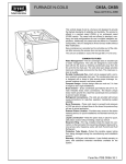
13
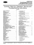
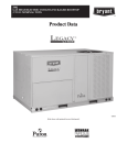
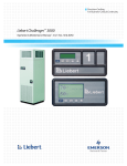
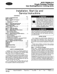
DIMENSIONS
C10896
Fig. 1 -- Dimensions 48HC*D17
14
DIMENSIONS (cont.)
UNIT
48HC17
STD UNIT
WEIGHT*
CORNER
WEIGHT (A)
CORNER
WEIGHT (B)
CORNER
WEIGHT (C)
CORNER
WEIGHT (D)
C.G.
LBS.
KG.
LBS.
KG.
LBS.
KG.
LBS.
KG.
LBS.
KG.
X
Y
Z
1892
860
401
182
449
204
565
257
505
230
48 [1219]
67 13/32 [1712]
16 1/2 [419]
* Standard unit weight is with low gas heat and without packaging
For other options and accessories, refer to the product data catalog
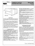
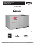
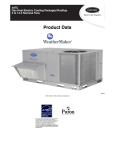
C11166
Fig. 2 -- Dimensions 48HC*D17
C
D
B
A
C09051
Fig. 3 -- Service Clearance
LOC
DIMENSION
A
36 ---in
Recommended clearance for airflow and service.
B
42 ---in
Recommended clearance for airflow and service.
18 ---in
1. No CO. 2. No Economizer. 3. No field installed disconnect on economizer hood side (Factory ---installed disconnect installed.
36 ---in
1. CO installed. 2. Vertical surface behind servicer is electrically non ---conductive (e.g., wood, fiberglass).
42 ---in
1. CO installed. 2 Vertical surface behind servicer is electrically conductive (e.g., metal, masonry)
96 ---in
1. Economizer and/or Power Exhaust installed. 2. Check for sources of flue products within 10 ---ft of economizer fresh air intake.
42 ---in
Recommended clearance for service.
C
D
CONDITION
NOTE: Unit not designed to have overhead obstruction. Contact Application Engineering for guidance on any application planning overhead
obstruction or for vertical clearances.
15
DIMENSIONS (cont.)
C10954
Fig. 4 -- Curb Dimensions 48HC*D17
16
DIMENSIONS (cont.)
C10892
Fig. 5 -- Dimensions 48HC*D20 -- 24
17
DIMENSIONS (cont.)
UNIT
STD UNIT
WEIGHT*
CORNER
WEIGHT (A)
CORNER
CORNER
WEIGHT (B) WEIGHT (C)
CORNER
WEIGHT (D)
C.G.
LBS.
KG.
LBS.
KG.
LBS.
KG.
LBS.
KG.
LBS.
KG.
X
Y
Z
48HC20
2102
956
474
215
390
177
593
269
582
265
47 1/2 [1207]
71 9/32 [1811]
16 1/2 [419]
48HC24
2247
1021
540
246
556
253
598
272
581
264
44 21/32 [1135]
71 5/8 [1819]
19 [483]
* Standard unit weight is with low gas heat and without packaging.
For other options and accessories, refer to the product data catalog.
C11167
Fig. 6 -- 48HCD20 -- 24
C
D
B
A
C10579
Fig. 7 -- Service Clearance
LOC
DIMENSION
A
36 ---in
Recommended clearance for airflow and service.
B
42 ---in
Recommended clearance for airflow and service.
18 ---in
1. No CO. 2. No Economizer. 3. No field installed disconnect on economizer hood side (Factory ---installed disconnect installed.
36 ---in
1. CO installed. 2. Vertical surface behind servicer is electrically non ---conductive (e.g., wood, fiberglass).
42 ---in
1. CO installed. 2 Vertical surface behind servicer is electrically conductive (e.g., metal, masonry)
96 ---in
1. Economizer and/or Power Exhaust installed. 2. Check for sources of flue products within 10 ---ft of economizer fresh air intake.
42 ---in
Recommended clearance for service.
C
D
CONDITION
NOTE: Unit not designed to have overhead obstruction. Contact Application Engineering for guidance on any application planning overhead
obstruction or for vertical clearances.
18
DIMENSIONS (cont.)
C10955
Fig. 8 -- Curb Dimensions 48HC*D20 -- 24
19
DIMENSIONS (cont.)
C10971
Fig. 9 -- Dimensions 48HC*D28
20
DIMENSIONS (cont.)
STD UNIT
WEIGHT*
UNIT
48HC28
CORNER
WEIGHT (A)
CORNER
CORNER
WEIGHT (B) WEIGHT (C)
CORNER
WEIGHT (D)
C.G.
LBS.
KG.
LBS.
KG.
LBS.
KG.
LBS.
KG.
LBS.
KG.
X
Y
Z
2292
1042
577
262
559
254
583
265
602
274
44 [1118]
77 17/32 [1969]
19 [483]
* Standard unit weight is with low gas heat and without packaging.
For other options and accessories, refer to the product data catalog.
C11168
Fig. 10 -- Dimensions 48HC*D28
C
D
B
A
C10998
Fig. 11 -- Service Clearance
LOC
DIMENSION
A
36 ---in
Recommended clearance for airflow and service.
B
42 ---in
Recommended clearance for airflow and service.
18 ---in
1. No CO. 2. No Economizer. 3. No field installed disconnect on economizer hood side (Factory ---installed disconnect installed.
36 ---in
1. CO installed. 2. Vertical surface behind servicer is electrically non ---conductive (e.g., wood, fiberglass).
42 ---in
1. CO installed. 2 Vertical surface behind servicer is electrically conductive (e.g., metal, masonry)
96 ---in
1. Economizer and/or Power Exhaust installed. 2. Check for sources of flue products within 10 ---ft of economizer fresh air intake.
42 ---in
Recommended clearance for service.
C
D
CONDITION
NOTE: Unit not designed to have overhead obstruction. Contact Application Engineering for guidance on any application planning overhead
obstruction or for vertical clearances.
21
DIMENSIONS (cont.)
C10956
Fig. 12 -- Curb Dimensions 48HC*D28
22
OPTIONS AND ACCESSORIES WEIGHT ADDERS
BASE UNIT WITH OPTIONS AND
ACCESSORIES
(Weight Adders)
Humidi--- MiZer
Base Unit Operating Weight
Power Exhaust
Economizer
Copper Tube/Fin Evaporator Coil
Low Gas Heat
Medium Gas Heat
High Gas Heat
Flue Discharge Deflector
Roof Curb 14--- in (356mm)
Roof Curb 24--- in (610mm)
Louvered Hail Guard
CO2 sensor
Return Smoke Detector
Supply Smoke Detector
Fan/Filter Status Switch
Non--- Fused Disconnect
HACR Circuit Breaker
Powered Convenience Outlet
Non--- Powered Convenience Outlet
Enthalpy Sensor
Differential Enthalpy Sensor
Two Position Motorized Damper
Manual Damper
Field Filter Track 4--- in (102mm)
MotorMaster Controller
Standard Static Motor/Drive
Medium Static Motor/Drive
High Static Motor/Drive
Barometric Relief Hood (Horizontal)
SAV System with VFD
48HC*17
lb
83
1892
125
170
110
85
90
113
7
240
340
60
5
5
5
2
15
15
35
5
2
3
50
35
12
35
0
5
11
25
20
kg
38
858
57
77
50
39
41
51
3
109
154
27
2
2
2
1
7
7
16
2
1
1
23
16
5
16
0
2
5
11
9
MAX WEIGHT ADD
48HC*20
48HC*24
lb
kg
lb
kg
83
38
88
40
2102
953
2247
1019
125
57
125
57
170
77
170
77
110
50
135
61
85
39
85
39
90
41
90
41
113
51
113
51
7
3
7
3
240
109
240
109
340
154
340
154
60
27
120
54
5
2
5
2
5
2
5
2
5
2
5
2
2
1
2
1
15
7
15
7
15
7
15
7
35
16
35
16
5
2
5
2
2
1
2
1
3
1
3
1
50
23
50
23
35
16
35
16
12
5
12
5
35
16
35
16
0
0
0
0
6
3
6
3
12
5
16
7
25
11
25
11
20
9
20
9
23
48HC*28
lb
kg
92
42
2292
1040
125
57
195
88
161
73
85
39
90
41
113
51
7
3
255
116
355
161
150
68
5
2
5
2
5
2
2
1
15
7
15
7
35
16
5
2
2
1
3
1
65
29
40
18
12
5
35
16
0
0
6
3
16
7
25
11
20
9
APPLICATION/SELECTION DATA
Min operating ambient temp (cooling):
Outdoor air application strategies:
In mechanical cooling mode, your Carrier rooftop unit can
safely operate down to an outdoor ambient temperature of
35_F (2_C). It is possible to provide cooling at lower
outdoor ambient temperatures by using less outside air,
economizers, and/or accessory low ambient kits.
Economizers reduce operating expenses and compressor
run time by providing a free source of cooling and a
means of ventilation to match application changing needs.
In fact, they should be considered for most applications.
Also, consider the various economizer control methods
and their benefits, as well as sensors required to
accomplish your application goals. Please contact your
local Carrier representative for assistance.
Max operating ambient temp (cooling):
The maximum operating ambient temperature for cooling
mode is 125_F (52_C). While cooling operation above
125_F (52_C) may be possible, it could cause either a
reduction in performance, reliability, or a protective action
by the unit’s internal safety devices.
Min mixed air temp (heating):
Using the factory settings, the minimum temperatures for
the mixed air (the combined temperature of the warm
return air and the cold outdoor air) entering the dimpled,
gas heat exchangers are:
Aluminized
50_F (10_C) continuous
45_F (7_C) intermittent
Stainless Steel
40_F (4_C) continuous
35_F (2_C) intermittent
Operating at lower mixed-- air temperatures may be
possible, if a field-- supplied, outdoor air thermostat
initiates both heat stages when the temperature is less than
the minimum temperatures listed above. Please contact
your local Carrier representative for assistance.
Min and max airflow (heating and cooling):
To maintain safe and reliable operation of your rooftop,
operate within the heating airflow limits during heating
mode and cooling airflow limits during cooling mode.
Operating above the max may cause blow-- off, undesired
airflow noise, or airflow related problems with the rooftop
unit. Operating below the min may cause problems with
coil freeze-- up and unsafe heating operation. Heating and
cooling limitations differ when evaluating operating CFM,
the minimum value is the HIGHER of the cooling and
heating minimum CFM values published in Table 5 and
the maximum value is the LOWER of the cooling and
heating minimum values published in Table 5.
Heating--to--cooling changeover:
Your unit will automatically change from heating to
cooling mode when using a thermostat with an
auto-- change-- over feature.
Airflow:
All units are draw-- through in cooling mode and
blow-- through in heating mode.
Motor limits, break horsepower (BHP):
Due to internal design of Carrier units, the air path, and
specially designed motors, the full horsepower (maximum
continuous BHP) band, as listed in Physical Data Table
Cooling, can be used with the utmost confidence. There is
no need for extra safety factors, as Carrier motors are
designed and rigorously tested to use the entire, listed
BHP range without either nuisance tripping or premature
motor failure.
Propane heating:
Propane has different physical qualities than natural gas.
As a result, Propane requires different fuel to air mixture.
To optimize the fuel/air mixture for Propane, Carrier sells
different burner orifices in an easy to install accessory kit.
To select the correct burner orifices or determine the heat
capacity for an Propane application, use either the
selection software, or the unit’s service manual.
High altitude heating:
High altitudes have less oxygen, which affects the fuel/air
mixture in heat exchangers. In order to maintain a proper
fuel/air mixture, heat exchangers operating in altitudes
above 2000 ft (610m) require different orifices. To select
the correct burner orifices or determine the heat capacity
for a high altitude application, use either the selection
software, or the unit’s service manual.
High altitudes have less oxygen, which means heat
exchangers need less fuel. The new gas orifices in this
field-- installed kit make the necessary adjustment for high
altitude applications. They restore the optimal fuel to air
mixture and maintain healthy combustion on altitudes
above 2000 ft (610m).
NOTE: Typical natural gas heating value ranges from
975 to 1050 Btu/ft3 at sea level nationally. The heating
value goes down approximately 1.7% per every thousand
feet elevation. Standard factory orifices can typically be
used up to 2000 ft (610m) elevation without any
operational issues.
NOTE: For installations in Canada, the input rating
should be derated by 10% for altitudes from 2000 ft
(610m) to 4500 ft (1372m) above sea level.
24
APPLICATION/SELECTION DATA (cont.)
Sizing a rooftop
Bigger isn’t necessarily better. While an air conditioner
needs to have enough capacity to meet the design loads, it
doesn’t need excess capacity. In fact, excess capacity
typically results in very poor part load performance and
humidity control.
Using higher design temperatures than ASHRAE
recommends for your location, adding “safety factors” to
the calculated load, are all signs of oversizing air
conditioners. Oversizing the air conditioner leads to poor
humidity control, reduced efficiency, higher utility bills,
larger indoor temperature swings, excessive noise, and
increased wear and tear on the air conditioner.
Rather than oversizing an air conditioner, engineers
should “right-- size” or even slightly undersize air
conditioners. Correctly sizing an air conditioner controls
humidity better; promotes efficiency; reduces utility bills;
extends equipment life, and maintains even, comfortable
temperatures. Please contact your local Carrier
representative for assistance.
Low ambient applications
The optional Carrier economizer can adequately cool your
space by bringing in fresh, cool outside air. In fact, when
so equipped, accessory low-- ambient kit may not be
necessary. In low ambient conditions, unless the outdoor
air
is
excessively
humid
or
contaminated,
economizer-- based “free cooling” is the preferred less
costly and energy conscious method.
In low ambient applications where outside air might not
be desired (such as contaminated or excessively humid
outdoor environments), your Carrier rooftop can operate
to ambient temperatures down to - 20_F (-- 29_C) using the
recommended field installed accessory Motormaster low
ambient controller or down to 0_F (-- 18_C) with the
factory installed low ambient controller option.
Application/Selection Option
Staged Air Volume (SAV) with Variable
Frequency Drive (VFD)
Carrier’s Staged Air Volume (SAV) system utilizes a
Variable Frequency Drive (VFD) to automatically adjust
the indoor fan motor speed in sequence with the units
cooling operation. Per ASHRAE 90.1 2010 standard
section 6.4.3.10.b, during the first stage of cooling
operation the VFD will adjust the fan motor to provide
2/3rd of the total cfm established for the unit. When a call
for the second stage of cooling is required, the VFD will
allow the total cfm for the unit established (100%).
During the heating mode, the VFD will allow total design
cfm (100%) operation and during the ventilation mode the
VFD will allow operation to 2/3rd of total cfm.
The VFD used in Carrier’s SAV system has soft start
capabilities to slowly ramp up the speeds, thus eliminating
any high inrush air volume during initial start-- up. It also
has internal over current protection for the fan motor and
a field installed display kit that allows adjustment and in
depth diagnostics of the VFD.
This SAV system is available on models with 2-- stage
cooling operation with electrical mechanical or RTU Open
(multi Protocol) controls. Both space sensor and
conventional thermostats controls can be used to provide
accurate control in any application.
The SAV system is very flexible for initial fan
performance set up and adjustment. The standard factory
shipped VFD is pre programmed to automatically stage
the fan speed between the first and second stage of
cooling. The unit fan performance static pressure and cfm
can be easily adjusted using the traditional means of
pulley adjustments. The other means to adjust the unit
static and cfm performance is to utilize the field installed
display module and adjust the frequency and voltage in
the VFD to required performance requirements. In either
case, once set up the VFD will automatically adjust the
speed between the cooling stage operation.
Selection software by Carrier saves time by performing
many of the steps above. Contact your Carrier sales
representative for assistance.
25
Table 8 – COOLING CAPACITIES
48HC*D17
62
EAT (wb)
4500 CFM
58
67
72
76
62
EAT (wb)
5250 CFM
58
67
72
76
62
EAT (wb)
6000 CFM
58
67
72
76
62
EAT (wb)
6750 CFM
58
67
72
76
62
EAT (wb)
7500 CFM
58
67
72
76
TC
SHC
TC
SHC
TC
SHC
TC
SHC
TC
SHC
TC
SHC
TC
SHC
TC
SHC
TC
SHC
TC
SHC
TC
SHC
TC
SHC
TC
SHC
TC
SHC
TC
SHC
TC
SHC
TC
SHC
TC
SHC
TC
SHC
TC
SHC
TC
SHC
TC
SHC
TC
SHC
TC
SHC
TC
SHC
75
158.3
137.3
166.8
123.1
182.9
100.0
200.5
76.1
----166.7
144.6
172.0
132.5
188.3
106.1
206.1
78.8
----173.8
150.8
176.3
140.9
192.3
112.0
210.4
81.2
----179.8
156.0
180.5
147.6
195.6
117.5
213.8
83.5
----185.1
160.6
185.2
152.5
198.1
122.8
216.6
85.6
-----
85
EA (dB)
80
158.3
158.3
166.8
146.1
182.9
123.1
200.5
99.5
215.4
80.2
166.7
166.7
172.0
158.8
188.3
132.7
206.1
105.6
221.2
83.6
173.8
173.8
176.3
170.2
192.3
142.0
210.4
111.4
225.6
86.7
179.8
179.8
180.5
179.2
195.6
150.8
213.8
117.0
229.1
89.6
185.1
185.1
185.2
185.2
198.1
159.3
216.6
122.3
231.9
92.4
85
179.2
179.2
169.0
169.0
182.9
146.1
200.5
122.8
215.4
105.0
188.8
188.8
185.1
185.1
188.3
159.3
206.1
132.5
221.2
111.7
196.8
196.8
199.5
199.5
192.3
172.0
210.4
141.7
225.6
117.9
203.7
203.7
210.7
210.7
195.6
184.1
213.8
150.5
229.1
124.0
209.6
209.6
218.0
218.0
198.1
195.9
216.6
159.0
231.9
129.9
2-- STAGE COOLING
75
152.6
132.4
159.5
119.7
174.9
96.7
191.6
72.9
----160.6
139.3
164.3
128.9
179.7
102.8
196.7
75.5
----167.2
145.1
168.5
136.9
183.4
108.5
200.6
77.9
----172.9
150.0
173.0
142.4
186.2
114.0
203.6
80.1
----177.7
154.2
177.9
146.4
188.6
119.2
206.1
82.2
-----
95
EA (dB)
80
152.6
152.6
159.5
142.6
174.9
119.8
191.6
96.2
205.8
77.1
160.6
160.6
164.3
155.1
179.7
129.3
196.7
102.3
211.0
80.3
167.2
167.2
168.5
165.9
183.4
138.5
200.6
108.0
215.0
83.3
172.9
172.9
173.0
173.0
186.2
147.3
203.6
113.5
218.1
86.2
177.7
177.7
177.9
177.9
188.6
155.7
206.1
118.8
220.7
88.9
AMBIENT TEMPERATURE
105
EA (dB)
85
75
80
85
75
172.9 146.6 146.6 166.1 140.2
172.9 127.2 146.6 166.1 121.6
165.6 151.8 151.8 161.9 143.6
165.6 116.1 139.0 161.9 112.3
174.9 166.3 166.3 166.3 157.2
142.8 93.2 116.3 139.4 89.7
191.6 182.2 182.2 182.2 172.2
119.5 69.5
92.8 116.1 66.0
205.8
--195.6 195.6
--101.7
--73.7
98.2
--181.9 154.0 154.0 174.4 147.0
181.9 133.6 154.0 174.4 127.6
181.2 156.3 156.3 177.0 147.8
181.2 125.0 151.0 177.0 120.9
179.7 170.7 170.7 170.7 161.0
155.9 99.3 125.8 152.4 95.6
196.7 186.7 186.7 186.7 176.2
129.1 72.1
98.8 125.6 68.5
211.0
--200.3 200.3
--108.2
--76.9 104.6
--189.4 160.2 160.2 181.4 152.7
189.4 139.0 160.2 181.4 132.5
194.9 160.5 160.5 188.9 152.9
194.9 132.1 160.5 188.9 125.8
183.4 173.9 173.9 173.9 164.0
168.5 104.9 134.9 164.8 101.2
200.6 190.2 190.2 190.2 179.3
138.2 74.4 104.5 134.6 70.7
215.0
--203.8 203.8
--114.5
--79.9 110.8
--195.8 165.5 165.5 187.4 157.5
195.8 143.5 165.5 187.4 136.7
203.6 165.6 165.6 194.9 157.7
203.6 136.3 165.6 194.9 129.8
186.2 176.5 176.5 176.8 166.2
180.5 110.4 143.6 176.8 106.5
203.6 192.9 192.9 192.9 181.6
147.0 76.5 109.9 143.3 72.8
218.1
--206.6 206.6
--120.5
--82.7 116.8
--201.3 170.0 170.0 192.5 161.6
201.3 147.5 170.0 192.5 140.2
209.3 170.1 170.1 200.2 161.8
209.3 140.0 170.1 200.2 133.2
192.1 178.6 178.6 188.1 168.1
192.1 115.5 151.8 188.1 111.5
206.1 195.1 195.1 195.1 183.5
155.5 78.6 115.2 151.7 74.9
220.7
--208.9 208.9
--126.3
--85.4 122.6
---
* See Minimum--- Maximum Airflow Ratings in Table 5. Do not operate outside these limits.
LEGEND:
----- Do not operate
Cfm
--- Cubic feet per minute (supply air)
EAT(db)
--- Entering air temperature (dry bulb)
EAT(wb)
--- Entering air temperature (wet bulb)
SHC
--- Sensible heat capacity
TC
--- Total capacity
26
15 TONS
115
EA (dB)
80
140.2
140.2
143.6
135.1
157.2
112.7
172.2
89.3
184.8
70.2
147.0
147.0
147.8
146.6
161.0
122.1
176.2
95.2
189.0
73.3
152.7
152.7
152.9
152.9
164.0
131.1
179.3
100.8
192.1
76.3
157.5
157.5
157.7
157.7
166.2
139.6
181.6
106.1
194.6
79.0
161.6
161.6
161.8
161.8
168.1
147.7
183.5
111.3
196.5
81.6
85
158.8
158.8
157.9
157.9
157.2
135.7
172.2
112.5
184.8
94.5
166.5
166.5
172.4
172.4
161.0
148.6
176.2
121.9
189.0
100.9
173.0
173.0
179.9
179.9
164.0
161.0
179.3
130.8
192.1
107.1
178.4
178.4
185.5
185.5
172.7
172.7
181.6
139.4
194.6
113.0
183.0
183.0
190.4
190.4
183.8
183.8
183.5
147.8
196.5
118.7
75
133.2
115.5
134.9
108.2
147.6
85.9
161.7
62.4
----139.5
121.0
139.6
114.9
150.9
91.7
165.3
64.8
----144.7
125.5
144.8
119.2
153.4
97.2
167.9
67.0
----149.0
129.3
149.1
122.8
155.4
102.4
169.9
69.1
----152.8
132.5
152.9
125.8
157.2
107.3
171.6
71.1
-----
125
EA (dB)
80
133.2
133.2
134.9
130.8
147.6
108.9
161.7
85.6
173.6
66.7
139.5
139.5
139.6
139.6
150.9
118.2
165.3
91.4
177.2
69.7
144.7
144.7
144.8
144.8
153.4
127.1
167.9
96.9
180.0
72.6
149.0
149.0
149.1
149.1
155.4
135.4
169.9
102.3
182.1
75.2
152.8
152.8
152.9
152.9
157.2
143.2
171.6
107.4
183.8
77.8
85
150.8
150.8
153.4
153.4
147.6
131.9
161.7
108.8
173.6
90.7
157.9
157.9
164.3
164.3
150.9
144.7
165.3
118.0
177.2
97.1
163.8
163.8
170.4
170.4
156.9
156.9
167.9
126.9
180.0
103.2
168.8
168.8
175.5
175.5
168.4
168.4
169.9
135.5
182.1
109.0
173.0
173.0
179.9
179.9
179.1
179.1
171.6
143.8
183.8
114.6
Table 9 – COOLING CAPACITIES
Temp (F) Air Ent
Condenser (Edb)
75
85
95
105
115
125
TC
SHC
kW
TC
SHC
kW
TC
SHC
kW
TC
SHC
kW
TC
SHC
kW
TC
SHC
kW
Temp (F) Air Ent
Condenser (Edb)
80
75
70
60
50
40
LEGEND
Edb --Ewb --kW --Idb --Iwb --SHC --TC
---
TC
SHC
kW
TC
SHC
kW
TC
SHC
kW
TC
SHC
kW
TC
SHC
kW
TC
SHC
kW
2-- STAGE COOLING
48HC017 (15 TONS) --- UNIT WITH HUMIDI---MIZER IN SUBCOOLING MODE
AIR ENTERING EVAPORATOR --- CFM
4,500
6,000
Air Entering Evaporator --- --- Ewb (F)
72
67
62
72
67
62
72
202.9
184.6
166.2
213.7
194.6
175.4
222.3
91.9
112.4
132.9
106.1
126.4
146.8
117.5
10.19
10.12
9.78
10.51
10.19
9.95
10.61
189.8
171.8
153.8
201.0
182.2
163.3
209.9
75.9
101.0
126.2
91.2
116.3
141.3
103.4
11.57
11.49
11.15
11.88
11.56
11.32
11.98
176.7
159.1
141.4
188.3
169.7
151.2
197.5
59.8
89.7
119.6
76.2
106.1
135.9
89.4
12.87
12.81
12.47
13.20
12.88
12.64
13.30
163.6
146.3
129.0
175.6
157.3
139.1
185.1
43.8
78.4
112.9
61.3
95.9
130.4
75.3
14.05
14.00
13.65
14.39
14.07
13.82
14.40
150.5
133.5
116.5
162.9
144.9
127.0
172.7
27.7
67.0
106.3
46.4
85.7
125.0
61.3
15.44
15.36
15.02
15.75
15.43
15.19
15.85
137.4
120.8
104.1
150.2
132.5
114.9
160.3
11.7
55.7
99.6
31.4
75.5
112.9
47.3
16.77
16.71
16.37
17.10
16.78
16.54
17.20
15 TONS (cont.)
7,500
67
202.5
137.7
10.36
190.4
128.4
11.73
178.2
119.2
13.05
166.1
109.9
14.24
154.0
100.6
15.60
141.9
91.3
16.95
48HC017 (15 TONS) --- UNIT WITH HUMIDI---MIZER IN HOT GAS REHEAT MODE
AIR ENTERING EVAPORATOR --- Ewb (F)
75 Dry Bulb
75 Dry Bulb
75 Dry Bulb
62.5 Wet Bulb
64 Wet Bulb
65.3 Wet Bulb
(50% Relative)
(56% Relative)
(60% Relative)
Air Entering Evaporator --- Cfm
4,500
6,000
7,500
4,500
6,000
7,500
4,500
6,000
64.50
71.00
73.30
68.40
74.50
77.30
71.20
79.70
12.60
24.90
36.80
6.80
13.70
23.90
--- 0.80
5.50
10.10
10.26
10.42
10.18
10.40
10.56
10.33
10.47
66.60
73.10
75.60
70.50
76.60
79.50
73.20
80.80
14.30
26.70
38.50
8.10
14.90
25.70
0.70
7.00
10.05
10.22
10.36
10.14
10.36
10.52
10.28
10.43
68.70
75.10
77.40
72.50
78.60
81.40
75.20
82.80
15.40
27.80
40.00
9.50
16.20
26.80
2.10
8.40
10.00
10.18
10.33
10.10
10.31
10.47
10.23
10.40
72.80
79.30
81.60
76.70
82.80
85.70
79.40
86.90
19.00
31.10
43.20
12.70
19.90
30.10
5.30
11.60
9.92
10.09
10.24
10.01
10.22
10.37
10.14
10.31
76.80
83.40
85.70
80.80
86.90
89.70
83.50
90.90
21.70
34.20
46.20
15.80
22.70
33.20
8.40
14.70
9.83
10.00
10.15
9.92
10.13
10.29
10.05
10.21
80.90
87.30
89.60
84.90
90.80
93.60
87.40
94.80
24.90
37.10
49.30
19.00
26.00
36.10
11.60
17.90
9.74
9.91
10.06
9.83
10.04
10.20
9.96
10.12
Entering Dry--- Bulb
Entering Wet--- Bulb
Compressor Motor Power Input
Leaving Dry--- Bulb
Leaving Wet--- Bulb
Sensible Heat Capacity (1000 Btuh) Gross
Total Capacity (1000 Btuh) Gross
62
182.7
158.0
10.12
170.8
153.5
11.49
159.0
149.0
12.81
147.1
144.4
14.00
135.3
133.4
15.36
123.5
123.0
16.71
7,500
80.60
13.80
10.67
82.90
15.00
10.62
84.90
16.30
10.58
88.80
20.00
10.49
92.80
22.80
10.39
96.70
26.20
10.30
NOTES:
1. Direct interpolation is permissible. Do not extrapolate.
2. The following formulas may be used:
sensible capacity (Btuh)
1.10 x cfm
tlwb = Wet--- bulb temperature corresponding to enthalpy of air
leaving evaporator coil (hlwb)
tldb = tedb –
total capacity (Btuh)
4.5 x cfm
Where: hewb = Enthalpy of air entering evaporator coil
hlwb = hewb –
27
Table 10 – COOLING CAPACITIES
48HC*D20
62
EAT (wb)
5250 CFM
58
67
72
76
62
EAT (wb)
6125 CFM
58
67
72
76
62
EAT (wb)
7000 CFM
58
67
72
76
62
EAT (wb)
7875 CFM
58
67
72
76
62
EAT (wb)
8750 CFM
58
67
72
76
TC
SHC
TC
SHC
TC
SHC
TC
SHC
TC
SHC
TC
SHC
TC
SHC
TC
SHC
TC
SHC
TC
SHC
TC
SHC
TC
SHC
TC
SHC
TC
SHC
TC
SHC
TC
SHC
TC
SHC
TC
SHC
TC
SHC
TC
SHC
TC
SHC
TC
SHC
TC
SHC
TC
SHC
TC
SHC
75
185.1
161.1
193.8
145.6
212.2
119.0
232.3
91.5
----194.7
169.4
199.6
156.5
218.0
126.2
238.5
94.7
----202.7
176.4
204.6
166.0
222.5
133.0
243.3
97.5
----209.6
182.3
209.8
173.4
226.1
139.6
247.0
100.2
----215.4
187.4
215.5
178.1
228.9
145.8
250.1
102.8
-----
85
EA (dB)
80
185.1
185.1
193.8
172.6
212.2
146.0
232.3
118.8
249.5
96.7
194.7
194.7
199.6
187.2
218.0
157.4
238.5
126.1
255.9
100.7
202.7
202.7
204.6
200.2
222.5
168.2
243.3
132.9
260.8
104.4
209.6
209.6
209.8
209.8
226.1
178.6
247.0
139.5
264.7
107.9
215.4
215.4
215.5
215.5
228.9
188.6
250.1
145.8
267.8
111.2
85
209.2
209.2
199.5
199.5
212.2
173.1
232.3
146.2
249.5
125.3
220.0
220.0
218.0
218.0
218.0
188.6
238.5
157.5
255.9
133.3
229.1
229.1
234.4
234.4
222.5
203.4
243.3
168.3
260.8
140.8
236.8
236.8
246.2
246.2
226.1
217.7
247.0
178.8
264.7
148.1
243.4
243.4
253.0
253.0
231.5
231.5
250.1
188.9
267.8
155.2
2-- STAGE COOLING
75
178.7
155.4
185.6
141.7
203.3
115.3
222.7
87.9
----187.8
163.3
191.1
152.3
208.7
122.4
228.4
91.0
----195.4
170.0
196.0
160.8
212.8
129.2
232.7
93.8
----201.8
175.6
202.0
167.0
216.0
135.6
236.2
96.5
----207.3
180.3
207.5
171.5
218.7
141.8
239.0
99.0
-----
95
EA (dB)
80
178.7
178.7
185.6
168.6
203.3
142.3
222.7
115.2
239.2
93.2
187.8
187.8
191.1
182.9
208.7
153.6
228.4
122.4
245.1
97.1
195.4
195.4
196.0
194.4
212.8
164.3
232.7
129.2
249.6
100.7
201.8
201.8
202.0
202.0
216.0
174.7
236.2
135.7
253.1
104.2
207.3
207.3
207.5
207.5
218.7
184.5
239.0
142.0
256.0
107.4
AMBIENT TEMPERATURE
105
EA (dB)
85
75
80
85
75
201.9 171.8 171.8 194.1 164.5
201.9 149.4 171.8 194.1 143.1
195.4 176.9 176.9 191.1 167.7
195.4 137.6 164.4 191.1 133.2
203.3 193.8 193.8 193.8 183.8
169.4 111.4 138.4 165.4 107.3
222.7 212.4 212.4 212.4 201.6
142.5 84.1 111.4 138.7 80.2
239.2
--228.2 228.2
--121.7
--89.5 117.9
--212.2 180.4 180.4 203.8 172.5
212.2 156.9 180.4 203.8 150.1
213.5 182.1 182.1 208.4 173.0
213.5 147.7 178.0 208.4 141.8
208.7 198.7 198.7 198.7 188.2
184.7 118.4 149.6 180.7 114.3
228.4 217.7 217.7 217.7 206.3
153.8 87.2 118.5 149.8 83.1
245.1
--233.6 233.6
--129.6
--93.3 125.6
--220.8 187.5 187.5 211.9 179.2
220.8 163.1 187.5 211.9 155.9
228.0 187.7 187.7 220.3 179.3
228.0 155.1 187.7 220.3 148.2
212.8 202.4 202.4 202.4 191.5
199.5 125.1 160.3 195.4 120.9
232.7 221.6 221.6 221.6 209.9
164.5 89.9 125.2 160.5 85.8
249.6
--237.7 237.7
--137.0
--96.9 133.0
--228.1 193.6 193.6 218.8 184.8
228.1 168.4 193.6 218.8 160.8
237.1 193.8 193.8 227.4 185.0
237.1 160.1 193.8 227.4 152.9
216.0 205.4 205.4 209.4 194.2
213.7 131.5 170.5 209.4 127.1
236.2 224.7 224.7 224.7 212.7
174.9 92.5 131.7 170.9 88.4
253.1
--240.9 240.9
--144.3
--100.2 140.2
--234.3 198.7 198.7 224.6 189.6
234.3 172.9 198.7 224.6 164.9
243.5 198.9 198.9 233.4 189.7
243.5 164.4 198.9 233.4 156.8
227.3 207.8 207.8 222.8 196.4
227.3 137.5 180.1 222.8 133.0
239.0 227.3 227.3 227.3 214.9
185.0 95.0 137.9 180.9 90.8
256.0
--243.5 243.5
--151.3
--103.5 147.1
---
* See Minimum--- Maximum Airflow Ratings in Table 5. Do not operate outside these limits.
LEGEND:
----- Do not operate
Cfm
--- Cubic feet per minute (supply air)
EAT(db)
--- Entering air temperature (dry bulb)
EAT(wb)
--- Entering air temperature (wet bulb)
SHC
--- Sensible heat capacity
TC
--- Total capacity
28
17.5 TONS
115
EA (dB)
80
164.5
164.5
167.7
159.8
183.8
134.3
201.6
107.4
216.6
85.6
172.5
172.5
173.0
171.5
188.2
145.4
206.3
114.4
221.4
89.3
179.2
179.2
179.3
179.3
191.5
156.0
209.9
121.1
225.1
92.8
184.8
184.8
185.0
185.0
194.2
166.0
212.7
127.5
227.9
96.1
189.6
189.6
189.7
189.7
196.4
175.5
214.9
133.7
230.2
99.3
85
185.8
185.8
186.4
186.4
183.8
161.3
201.6
134.6
216.6
113.8
194.9
194.9
201.2
201.2
188.2
176.5
206.3
145.7
221.4
121.5
202.5
202.5
210.5
210.5
191.5
191.0
209.9
156.3
225.1
128.8
208.9
208.9
217.1
217.1
204.8
204.8
212.7
166.6
227.9
135.9
214.2
214.2
222.7
222.7
217.9
217.9
214.9
176.5
230.2
142.8
75
156.7
136.3
158.2
128.3
173.1
103.0
190.1
76.0
----164.1
142.8
164.3
135.8
177.1
109.9
194.3
78.9
----170.3
148.1
170.4
140.8
180.0
116.4
197.4
81.6
----175.5
152.7
175.6
145.1
182.4
122.5
199.9
84.1
----179.9
156.5
180.0
148.8
184.5
128.2
201.8
86.4
-----
125
EA (dB)
80
156.7
156.7
158.2
154.7
173.1
130.0
190.1
103.2
204.3
81.5
164.1
164.1
164.3
164.3
177.1
141.0
194.3
110.1
208.5
85.1
170.3
170.3
170.4
170.4
180.0
151.4
197.4
116.7
211.7
88.5
175.5
175.5
175.6
175.6
182.4
161.2
199.9
123.1
----179.9
179.9
180.0
180.0
184.5
170.4
201.8
129.2
-----
85
177.0
177.0
181.1
181.1
173.1
157.0
190.1
130.4
204.3
109.5
185.5
185.5
192.8
192.8
177.1
172.1
194.3
141.4
208.5
117.1
192.4
192.4
200.0
200.0
186.4
186.4
197.4
151.9
211.7
124.4
198.3
198.3
206.1
206.1
199.9
199.9
199.9
162.1
----203.2
203.2
211.2
211.2
212.6
212.6
201.8
172.0
-----
Table 11 – COOLING CAPACITIES
Temp (F) Air Ent
Condenser (Edb)
75
85
95
105
115
125
TC
SHC
kW
TC
SHC
kW
TC
SHC
kW
TC
SHC
kW
TC
SHC
kW
TC
SHC
kW
Temp (F) Air Ent
Condenser (Edb)
80
75
70
60
50
40
LEGEND
Edb --Ewb --kW --Idb --Iwb --SHC --TC
---
TC
SHC
kW
TC
SHC
kW
TC
SHC
kW
TC
SHC
kW
TC
SHC
kW
TC
SHC
kW
2-- STAGE COOLING
48HC020 (17.5 TONS) --- UNIT WITH HUMIDI---MIZER IN SUBCOOLING MODE
AIR ENTERING EVAPORATOR --- CFM
5,250
7,000
Air Entering Evaporator --- --- Ewb (F)
72
67
62
72
67
62
72
232.0
211.3
190.6
242.4
221.0
199.7
250.7
110.9
133.7
156.4
127.6
150.3
173.0
141.1
12.45
12.16
11.81
12.74
12.41
12.02
12.93
215.9
195.7
175.5
226.0
205.2
184.4
234.2
90.6
118.8
147.0
108.4
136.6
164.9
122.7
13.48
13.20
12.88
13.77
13.47
13.07
13.96
199.7
180.0
160.3
209.7
189.4
169.1
217.6
70.3
104.0
137.7
89.2
123.0
156.7
104.4
14.60
14.25
13.94
14.89
14.51
14.15
15.08
183.6
164.5
145.2
193.3
173.5
153.8
201.0
50.0
89.1
128.3
70.0
109.3
148.6
86.0
15.64
15.36
15.--- 01
15.93
15.60
15.21
16.12
167.5
148.8
130.1
176.9
157.7
138.5
184.5
29.7
74.3
118.9
50.7
95.6
138.1
67.7
16.70
16.38
15.82
16.98
16.63
16.03
17.17
151.4
133.2
115.0
160.6
141.9
123.1
167.9
9.4
59.5
109.6
31.5
81.9
123.0
49.3
17.71
17.39
17.09
18.01
17.65
17.30
18.20
17.5 TONS (cont.)
8,750
67
228.9
163.7
12.51
212.8
151.0
13.58
196.8
138.2
14.63
180.8
125.5
15.72
164.8
112.7
16.75
148.8
100.0
17.76
62
207.0
186.4
12.18
191.5
179.2
13.23
176.1
172.1
14.31
160.6
158.6
15.37
145.1
145.1
16.19
129.7
129.7
17.46
48HC020 (17.5 TONS) --- UNIT WITH HUMIDI---MIZER IN HOT GAS REHEAT MODE
AIR ENTERING EVAPORATOR --- Ewb (F)
75 Dry Bulb
75 Dry Bulb
75 Dry Bulb
62.5 Wet Bulb
64 Wet Bulb
65.3 Wet Bulb
(50% Relative)
(56% Relative)
(60% Relative)
Air Entering Evaporator --- Cfm
5,250
7,000
8,750
5,250
7,000
8,750
5,250
7,000
8,750
67.80
71.30
74.10
70.50
74.80
79.80
73.30
78.20
82.40
9.00
26.50
41.70
2.20
13.20
26.90
--- 5.20
2.90
13.80
11.65
11.75
11.87
11.82
11.90
11.98
11.93
12.10
12.19
72.50
76.00
78.80
75.00
79.20
84.30
78.00
83.00
86.90
13.40
30.90
46.10
6.50
18.00
31.30
--- 2.10
7.20
17.90
11.44
11.54
11.66
11.61
11.68
11.75
11.70
11.86
11.95
77.10
80.60
83.40
79.50
83.90
88.90
82.40
87.30
91.10
17.60
34.70
49.90
10.80
22.20
35.10
3.20
11.50
22.20
11.22
11.33
11.45
11.40
11.46
11.54
11.49
11.64
11.75
86.30
89.90
92.70
88.80
93.20
98.20
91.70
96.60
100.50
26.20
43.20
58.40
19.40
30.80
43.60
11.60
20.10
30.70
10.76
10.86
10.98
10.93
11.00
11.07
11.03
11.18
11.28
95.50
99.10
101.90
98.00
102.40
107.40
101.00
106.00
109.80
34.80
51.80
67.00
28.00
39.40
52.20
20.10
28.70
39.40
10.33
10.43
10.55
10.50
10.52
10.63
10.59
10.74
10.85
104.80
108.40
111.20
107.30
111.70
116.60
110.30
115.30
119.10
43.40
60.40
75.60
36.60
48.00
60.80
28.80
37.30
47.90
9.87
9.97
10.09
10.04
10.11
10.18
10.14
10.28
10.40
Entering Dry--- Bulb
Entering Wet--- Bulb
Compressor Motor Power Input
Leaving Dry--- Bulb
Leaving Wet--- Bulb
Sensible Heat Capacity (1000 Btuh) Gross
Total Capacity (1000 Btuh) Gross
NOTES:
1. Direct interpolation is permissible. Do not extrapolate.
2. The following formulas may be used:
sensible capacity (Btuh)
1.10 x cfm
tlwb = Wet--- bulb temperature corresponding to enthalpy of air
leaving evaporator coil (hlwb)
tldb = tedb –
total capacity (Btuh)
4.5 x cfm
Where: hewb = Enthalpy of air entering evaporator coil
hlwb = hewb –
29
Table 12 – COOLING CAPACITIES
48HC*D24
62
EAT (wb)
6000 CFM
58
67
72
76
62
EAT (wb)
7000 CFM
58
67
72
76
62
EAT (wb)
8000 CFM
58
67
72
76
62
EAT (wb)
9000 CFM
58
67
72
76
62
EAT (wb)
10,000 CFM
58
67
72
76
TC
SHC
TC
SHC
TC
SHC
TC
SHC
TC
SHC
TC
SHC
TC
SHC
TC
SHC
TC
SHC
TC
SHC
TC
SHC
TC
SHC
TC
SHC
TC
SHC
TC
SHC
TC
SHC
TC
SHC
TC
SHC
TC
SHC
TC
SHC
TC
SHC
TC
SHC
TC
SHC
TC
SHC
TC
SHC
75
214.4
186.3
226.8
167.0
248.4
136.5
271.9
105.1
----225.8
196.2
233.9
179.4
255.7
144.7
279.4
108.7
----235.3
204.5
239.7
190.7
261.3
152.3
285.3
111.9
----243.5
211.6
245.4
199.7
265.6
159.6
289.9
114.9
----250.4
217.7
250.8
207.0
269.2
166.6
293.7
117.8
-----
85
EA (dB)
80
214.4
214.4
226.8
197.3
248.4
167.1
271.9
136.0
291.7
110.7
225.8
225.8
233.9
214.1
255.7
179.7
279.4
144.1
299.4
115.3
235.3
235.3
239.7
229.4
261.3
191.8
285.3
151.7
305.4
119.4
243.5
243.5
245.4
241.3
265.6
203.3
289.9
159.0
310.1
123.2
250.4
250.4
250.8
250.8
269.2
214.5
293.7
166.0
313.9
126.8
85
242.5
242.5
227.7
227.7
248.4
197.6
271.9
167.0
291.7
143.7
255.3
255.3
248.8
248.8
255.7
214.8
279.4
179.6
299.4
152.9
266.2
266.2
268.1
268.1
261.3
231.2
285.3
191.5
305.4
161.0
275.4
275.4
282.9
282.9
265.6
247.1
289.9
203.0
310.1
168.9
283.2
283.2
294.6
294.6
269.2
262.5
293.7
214.2
313.9
176.5
2-- STAGE COOLING
75
207.0
179.9
217.3
162.4
237.9
132.2
260.3
100.8
----217.8
189.3
223.8
174.6
244.6
140.2
267.3
104.3
----226.8
197.1
229.4
185.4
249.6
147.7
272.5
107.5
----234.5
203.8
235.4
193.2
253.6
154.9
276.7
110.4
----240.9
209.4
241.1
199.0
256.8
161.9
280.1
113.2
-----
95
EA (dB)
80
207.0
207.0
217.3
192.7
237.9
162.7
260.3
131.7
279.2
106.5
217.8
217.8
223.8
209.2
244.6
175.2
267.3
139.7
286.2
110.9
226.8
226.8
229.4
223.7
249.6
187.1
272.5
147.2
291.6
114.9
234.5
234.5
235.4
233.9
253.6
198.6
276.7
154.4
295.8
118.6
240.9
240.9
241.1
241.1
256.8
209.7
280.1
161.3
299.3
122.2
AMBIENT TEMPERATURE
105
EA (dB)
85
75
80
85
75
234.2 199
199 225.1 190.2
234.2 173
199 225.1 165.3
223.0 206.9 206.9 218 195.8
223.0 157.6 187.8 218 152.3
237.9 226.6 226.6 226.6 214.3
193.2 127.5 158 188.4 122.5
260.3 247.9 247.9 247.9 234.5
162.5 96.3 127.1 157.9 91.4
279.2
--265.7 265.7
--139.5
--102 134.7
--246.3 209.1 209.1 236.5 199.6
246.3 181.7 209.1 236.5 173.4
243.8 213.1 213.1 238.2 201.4
243.8 169.4 203.8 238.2 163.7
244.6 232.6 232.6 232.6 219.6
210.2 135.4 170.4 205.4 130.3
267.3 254.1 254.1 254.1 240.1
175.1 99.6
135 170.3 94.7
286.2
--272.1 272.1
--148.2
--106.3 143.3
--256.5 217.5 217.5 246 207.4
256.5 189 217.5 246 180.2
262.0 219
219 253.3 208.3
262.0 178.6 215.9 253.3 170.4
249.6 237.1 237.1 237.1 223.6
226.6 142.9 182.2 221.6 137.7
272.5 258.9 258.9 258.9 244.2
186.9 102.7 142.4 182
97.7
291.6
--276.8 276.8
--156.2
--110.1 151.2
--265.2 224.6 224.6 254 213.9
265.2 195.2 224.6 254 185.9
274.6 225
225 264.3 214.4
274.6 185.6 224.9 264.3 176.8
253.6 240.7 240.7 240.7 226.8
242.3 150 193.6 237.3 144.7
276.7 262.6 262.6 262.6 247.5
198.3 105.6 149.5 193.3 100.5
295.8
--280.6 280.6
--164.1
--113.8 159
--272.5 230.7 230.7 260.9 219.5
272.5 200.5 230.7 260.9 190.7
283.3 231.1 231.1 271.4 219.6
283.3 190.7 231.1 271.4 181.2
257.6 243.5 243.5 252.3 229.4
257.6 156.8 204.5 252.3 151.3
280.1 265.6 265.6 265.6 250.2
209.3 108.3 156.3 204.3 103.2
299.3
--283.7 283.7
--171.6
--117.3 166.5
---
* See Minimum--- Maximum Airflow Ratings in Table 5. Do not operate outside these limits.
LEGEND:
----- Do not operate
Cfm
--- Cubic feet per minute (supply air)
EAT(db)
--- Entering air temperature (dry bulb)
EAT(wb)
--- Entering air temperature (wet bulb)
SHC
--- Sensible heat capacity
TC
--- Total capacity
30
20 TONS
115
EA (dB)
80
190.2
190.2
195.8
182.4
214.3
152.9
234.5
122.1
251.3
97.2
199.6
199.6
201.4
197.8
219.6
165.2
240.1
129.9
256.9
101.3
207.4
207.4
208.3
206.2
223.6
177.0
244.2
137.2
261.2
105.1
213.9
213.9
214.4
214.3
226.8
188.3
247.5
144.2
264.4
108.7
219.5
219.5
219.6
219.6
229.4
198.9
250.2
151.0
267.1
112.1
85
215.2
215.2
212.5
212.5
214.3
183.4
234.5
152.9
251.3
129.7
225.7
225.7
231.8
231.8
219.6
200.2
240.1
165.1
256.9
138.0
234.5
234.5
241.9
241.9
223.6
216.3
244.2
176.7
261.2
146.0
241.9
241.9
251.7
251.7
231.8
231.8
247.5
188.0
264.4
153.6
248.2
248.2
258.0
258.0
246.4
246.4
250.2
198.8
267.1
161.0
75
180.6
157.0
183.7
146.6
201.0
117.2
220.1
86.3
----189.2
164.4
190.0
155.9
205.7
124.9
224.9
89.5
----196.3
170.6
196.7
162.3
209.2
132.2
228.6
92.4
----202.3
175.8
202.5
167.1
212.0
139.0
231.4
95.2
----207.3
180.2
207.5
171.2
214.3
145.5
233.7
97.8
-----
125
EA (dB)
80
180.6
180.6
183.7
176.5
201.0
147.6
220.1
116.9
235.8
92.1
189.2
189.2
190.0
188.7
205.7
159.8
224.9
124.6
240.7
96.1
196.3
196.3
196.7
196.7
209.2
171.4
228.6
131.8
244.4
99.8
202.3
202.3
202.5
202.5
212.0
182.4
231.4
138.7
247.3
103.4
207.3
207.3
207.5
207.5
214.3
192.8
233.7
145.4
249.6
106.7
85
204.3
204.3
206.4
206.4
201.0
178.0
220.1
147.6
235.8
124.3
214.0
214.0
221.5
221.5
205.7
194.7
224.9
159.7
240.7
132.6
222.0
222.0
231.0
231.0
210.6
210.6
228.6
171.2
244.4
140.4
228.8
228.8
237.8
237.8
225.8
225.8
231.4
182.3
247.3
147.9
234.5
234.5
243.7
243.7
240.0
240.0
233.7
193.1
249.6
155.1
Table 13 – COOLING CAPACITIES
Temp (F) Air Ent
Condenser (Edb)
75
85
95
105
115
125
TC
SHC
kW
TC
SHC
kW
TC
SHC
kW
TC
SHC
kW
TC
SHC
kW
TC
SHC
kW
Temp (F) Air Ent
Condenser (Edb)
80
75
70
60
50
40
LEGEND
Edb --Ewb --kW --Idb --Iwb --SHC --TC
---
TC
SHC
kW
TC
SHC
kW
TC
SHC
kW
TC
SHC
kW
TC
SHC
kW
TC
SHC
kW
2-- STAGE COOLING
48HC024 (20 TONS) --- UNIT WITH HUMIDI---MIZER IN SUBCOOLING MODE
AIR ENTERING EVAPORATOR --- CFM
6,000
8,000
Air Entering Evaporator --- --- Ewb (F)
72
67
62
72
67
62
72
281.6
256.5
231.3
293.1
267.0
240.9
302.3
114.7
141.0
167.4
140.6
166.6
192.6
161.6
13.52
13.25
12.95
13.82
13.46
13.21
13.97
261.3
236.9
212.4
272.1
247.7
221.3
280.7
90.9
123.5
156.1
118.8
151.1
183.3
141.4
14.95
14.68
14.48
15.25
14.89
14.64
15.40
241.1
217.2
193.4
251.1
226.4
201.7
259.2
67.2
106.0
144.8
97.1
120.1
174.1
121.2
16.52
16.25
15.95
16.82
16.46
16.21
16.97
220.8
197.5
174.4
230.2
206.2
182.2
237.7
43.4
88.4
133.5
75.3
120.1
164.9
101.0
18.09
17.82
17.52
18.39
18.03
17.78
18.54
200.5
178.0
155.5
209.2
185.9
162.6
216.2
19.7
70.9
122.2
53.5
104.6
155.7
80.9
19.65
19.38
19.08
19.95
19.59
19.34
20.10
180.2
158.4
136.5
188.2
165.6
143.0
194.7
--- 4.1
53.4
110.8
31.7
89.1
142.2
60.7
20.59
20.32
20.02
20.89
20.53
20.28
21.04
20 TONS (cont.)
10,000
67
275.4
187.3
13.60
254.6
173.4
15.03
233.8
159.5
16.60
213.0
145.7
18.17
192.2
131.8
19.73
171.4
118.0
20.67
62
248.6
212.9
13.31
228.5
205.4
14.74
208.4
197.8
16.31
188.4
178.9
17.88
168.7
161.2
19.44
148.2
145.1
20.38
48HC024 (20 TONS) --- UNIT WITH HUMIDI---MIZER IN HOT GAS REHEAT MODE
AIR ENTERING EVAPORATOR --- Ewb (F)
75 Dry Bulb
75 Dry Bulb
75 Dry Bulb
62.5 Wet Bulb
64 Wet Bulb
65.3 Wet Bulb
(50% Relative)
(56% Relative)
(60% Relative)
Air Entering Evaporator --- Cfm
6,000
8,000
10,000
6,000
8,000
10,000
6,000
8,000
10,000
115.20
123.30
130.60
120.40
129.30
138.20
122.80
135.00
143.70
40.80
58.30
76.10
32.30
45.50
60.40
20.10
34.30
48.00
13.24
13.32
13.39
13.43
13.57
13.65
13.49
13.68
13.74
119.80
128.60
135.90
125.50
135.30
143.20
128.00
139.50
148.40
45.60
62.80
82.10
37.00
49.80
65.20
24.30
38.70
52.60
13.05
13.10
13.17
13.21
13.35
13.43
13.27
13.46
13.52
122.50
133.10
140.20
129.80
140.70
147.60
132.40
144.40
153.20
49.80
76.00
86.10
41.10
54.30
69.20
28.80
41.40
56.80
12.80
12.87
12.94
12.98
13.12
13.20
13.04
13.23
13.29
133.80
142.50
149.60
139.30
150.40
157.40
141.50
154.20
163.00
58.60
76.00
95.00
50.20
63.50
78.10
37.80
52.10
65.90
12.34
12.42
12.49
12.53
12.67
12.75
12.59
12.78
12.84
143.50
151.80
159.30
149.00
160.00
167.00
151.30
163.60
172.50
67.70
84.80
103.80
59.10
72.40
87.00
46.70
61.00
74.90
11.88
11.95
12.03
12.07
12.21
12.29
12.13
12.32
12.38
153.20
161.30
168.70
158.60
169.20
176.60
160.80
173.10
182.00
76.50
93.60
111.60
68.00
81.50
95.80
55.80
69.80
84.00
11.42
11.49
11.56
11.60
11.74
11.82
11.66
11.85
11.91
Entering Dry--- Bulb
Entering Wet--- Bulb
Compressor Motor Power Input
Leaving Dry--- Bulb
Leaving Wet--- Bulb
Sensible Heat Capacity (1000 Btuh) Gross
Total Capacity (1000 Btuh) Gross
NOTES:
1. Direct interpolation is permissible. Do not extrapolate.
2. The following formulas may be used:
sensible capacity (Btuh)
1.10 x cfm
tlwb = Wet--- bulb temperature corresponding to enthalpy of air
leaving evaporator coil (hlwb)
tldb = tedb –
total capacity (Btuh)
4.5 x cfm
Where: hewb = Enthalpy of air entering evaporator coil
hlwb = hewb –
31
Table 14 – COOLING CAPACITIES
48HC*D28
62
EAT (wb)
7,500 CFM
58
67
72
76
62
EAT (wb)
8,750 CFM
58
67
72
76
62
EAT (wb)
10,000 CFM
58
67
72
76
62
EAT (wb)
11,250 CFM
58
67
72
76
62
EAT (wb)
12,500 CFM
58
67
72
76
TC
SHC
TC
SHC
TC
SHC
TC
SHC
TC
SHC
TC
SHC
TC
SHC
TC
SHC
TC
SHC
TC
SHC
TC
SHC
TC
SHC
TC
SHC
TC
SHC
TC
SHC
TC
SHC
TC
SHC
TC
SHC
TC
SHC
TC
SHC
TC
SHC
TC
SHC
TC
SHC
TC
SHC
TC
SHC
75
264.4
229.9
278.7
206.8
305.3
169.0
334.0
129.9
----278.2
241.9
287.2
222.1
314.0
179.1
343.0
134.3
----289.7
251.9
294.6
234.7
320.6
188.6
350.0
138.4
----299.4
260.3
302.2
244.8
325.9
197.6
355.5
142.1
----307.7
267.6
308.4
254.6
330.2
206.3
360.1
145.7
-----
85
EA (dB)
80
264.4
264.4
278.7
244.6
305.3
207.0
334.0
168.5
358.2
137.0
278.2
278.2
287.2
265.2
314.0
222.7
343.0
178.5
367.3
142.6
289.7
289.7
294.6
282.1
320.6
237.7
350.0
187.9
374.4
147.7
299.4
299.4
302.2
295.4
325.9
252.1
355.5
197.0
380.0
152.4
307.7
307.7
308.4
308.4
330.2
265.9
360.1
205.7
384.6
157.0
85
298.9
298.9
282.4
282.4
305.3
245.0
334.0
207.1
358.2
178.2
314.5
314.5
308.3
308.3
314.0
266.4
343.0
222.6
367.3
189.4
327.5
327.5
329.6
329.6
320.6
286.8
350.0
237.5
374.4
199.5
338.4
338.4
346.0
346.0
325.9
306.5
355.5
251.8
380.0
209.4
347.9
347.9
362.2
362.2
330.2
325.5
360.1
265.7
384.6
218.9
2-- STAGE COOLING
75
254.6
221.4
266.3
200.9
291.9
163.4
319.4
124.5
----267.8
232.8
274.3
215.7
299.8
173.3
327.7
128.8
----278.7
242.3
282.2
226.8
305.9
182.7
334.0
132.8
----287.8
250.2
289.3
236.7
310.7
191.7
339.1
136.4
----295.7
257.1
295.9
244.4
314.6
200.3
343.2
139.9
-----
95
EA (dB)
80
254.6
254.6
266.3
238.7
291.9
201.4
319.4
163.0
342.4
131.7
267.8
267.8
274.3
258.6
299.8
216.9
327.7
172.9
350.8
137.1
278.7
278.7
282.2
273.3
305.9
231.8
334.0
182.2
357.3
142.1
287.8
287.8
289.3
286.2
310.7
246.1
339.1
191.2
362.4
146.8
295.7
295.7
295.9
295.9
314.6
259.7
343.2
199.8
366.5
151.2
AMBIENT TEMPERATURE
105
EA (dB)
85
75
80
85
75
287.9 244.1 244.1 276.0 232.7
287.9 212.2 244.1 276.0 202.3
276.4 252.8 252.8 269.8 238.5
276.4 194.6 232.2 269.8 187.7
291.9 277.3 277.3 277.3 261.5
239.4 157.4 195.3 233.3 151.0
319.4 303.6 303.6 303.6 286.5
201.5 118.7 157.1 195.5 112.5
342.4
--325.4 325.4
--172.9
--126.0 166.9
--302.8 256.5 256.5 289.9 244.2
302.8 223.0 256.5 289.9 212.3
301.5 260.8 260.8 291.7 247.0
301.5 207.7 249.7 291.7 199.0
299.8 284.4 284.4 284.4 267.8
260.6 167.2 210.8 254.3 160.7
327.7 311.1 311.1 311.1 293.1
216.9 122.9 166.9 210.8 116.6
350.8
--333.0 333.0
--183.5
--131.2 177.3
--315.0 266.6 266.6 301.4 253.6
315.0 231.8 266.6 301.4 220.5
319.7 268.7 268.7 309.1 254.1
319.7 218.4 263.7 309.1 209.7
305.9 289.9 289.9 289.9 272.7
280.9 176.5 225.5 274.5 169.8
334.0 316.8 316.8 316.8 298.2
231.7 126.8 176.1 225.5 120.4
357.3
--338.7 338.7
--193.7
--136.1 187.4
--325.4 275.2 275.2 311.1 261.4
325.4 239.2 275.2 311.1 227.3
335.7 275.5 275.5 323.5 262.1
335.7 227.5 275.5 323.5 216.4
310.7 294.2 294.2 294.2 276.6
300.4 185.3 239.6 293.9 178.5
339.1 321.3 321.3 321.3 302.2
245.9 130.4 185.0 239.6 123.9
362.4
--343.3 343.3
--203.4
--140.7 197.0
--334.2 282.5 282.5 319.3 268.2
334.2 245.6 282.5 319.3 233.2
347.4 283.1 283.1 332.4 268.4
347.4 233.8 283.1 332.4 221.7
319.2 297.8 297.8 312.3 279.8
319.2 193.8 253.1 312.3 186.7
343.2 325.0 325.0 325.0 305.4
259.7 133.8 193.5 253.3 127.3
366.5
--346.9 346.9
--212.9
--145.1 206.3
---
* See Minimum--- Maximum Airflow Ratings in Table 5. Do not operate outside these limits.
LEGEND:
----- Do not operate
Cfm
--- Cubic feet per minute (supply air)
EAT(db)
--- Entering air temperature (dry bulb)
EAT(wb)
--- Entering air temperature (wet bulb)
SHC
--- Sensible heat capacity
TC
--- Total capacity
32
25 TONS
115
EA (dB)
80
232.7
232.7
238.5
225.0
261.5
188.9
286.5
150.8
307.1
119.9
244.2
244.2
247.0
240.0
267.8
204.2
293.1
160.4
313.8
125.0
253.6
253.6
254.1
254.1
272.7
218.8
298.2
169.6
318.9
129.7
261.4
261.4
262.1
262.1
276.6
232.6
302.2
178.3
322.8
134.2
268.2
268.2
268.4
268.4
279.8
245.7
305.4
186.8
325.9
138.5
85
263.1
263.1
262.4
262.4
261.5
226.8
286.5
189.2
307.1
160.4
276.1
276.1
280.9
280.9
267.8
247.7
293.1
204.3
313.8
170.7
286.7
286.7
298.4
298.4
272.7
267.7
298.2
218.8
318.9
180.6
295.6
295.6
307.7
307.7
286.7
286.7
302.2
232.8
322.8
190.2
303.2
303.2
315.2
315.2
304.7
304.7
305.4
246.3
325.9
199.3
75
220.3
191.5
223.9
178.7
244.5
144.2
268.1
106.0
----230.8
200.7
232.0
189.7
250.0
153.7
273.8
109.9
----239.4
208.2
239.7
197.9
254.3
162.8
278.3
113.6
----246.6
214.4
246.8
203.8
257.7
171.2
281.8
117.1
----252.7
219.7
252.8
208.8
260.6
179.0
284.6
120.4
-----
125
EA (dB)
80
220.3
220.3
223.9
215.0
244.5
182.1
268.1
144.2
287.4
113.4
230.8
230.8
232.0
229.4
250.0
197.2
273.8
153.6
293.2
118.4
239.4
239.4
239.7
239.7
254.3
211.5
278.3
162.6
297.5
123.0
246.6
246.6
246.8
246.8
257.7
225.1
281.8
171.3
300.9
127.3
252.7
252.7
252.8
252.8
260.6
237.4
284.6
179.7
303.5
131.5
85
249.1
249.1
251.3
251.3
244.5
219.9
268.1
182.3
287.4
153.4
261.0
261.0
269.1
269.1
250.0
240.6
273.8
197.3
293.2
163.7
270.7
270.7
281.4
281.4
260.3
260.3
278.3
211.7
297.5
173.5
278.8
278.8
289.8
289.8
278.9
278.9
281.8
225.5
300.9
182.8
285.7
285.7
296.9
296.9
295.9
295.9
284.6
238.9
303.5
191.7
Table 15 – COOLING CAPACITIES
Temp (F) Air Ent
Condenser (Edb)
75
85
95
105
115
125
TC
SHC
kW
TC
SHC
kW
TC
SHC
kW
TC
SHC
kW
TC
SHC
kW
TC
SHC
kW
Temp (F) Air Ent
Condenser (Edb)
80
75
70
60
50
40
LEGEND
Edb --Ewb --kW --Idb --Iwb --SHC --TC
---
TC
SHC
kW
TC
SHC
kW
TC
SHC
kW
TC
SHC
kW
TC
SHC
kW
TC
SHC
kW
2-- STAGE COOLING
48HC028 (25 TONS) --- UNIT WITH HUMIDI---MIZER IN SUBCOOLING MODE
AIR ENTERING EVAPORATOR --- CFM
7,500
10,000
Air Entering Evaporator --- --- Ewb (F)
72
67
62
72
67
62
72
351.3
319.5
287.8
370.4
337.3
304.1
385.8
166.5
199.4
232.3
191.2
245.6
258.5
211.4
16.75
16.55
15.20
17.30
16.75
15.85
17.80
327.5
296.4
265.3
346.1
313.6
281.2
361.1
137.4
178.2
219.0
162.6
204.5
246.4
183.3
18.65
18.45
17.25
19.20
18.65
17.80
19.45
303.7
273.3
242.9
321.8
290.0
258.3
336.4
108.2
157.0
205.8
134.0
184.1
234.3
155.1
20.60
20.40
19.34
21.15
20.60
19.95
21.60
279.9
250.2
220.4
297.5
266.4
235.3
311.7
79.0
135.8
192.5
105.4
163.8
222.2
127.1
22.85
22.65
21.45
23.40
22.85
22.05
23.70
256.2
227.1
198.0
273.2
242.8
212.4
287.0
49.9
114.5
179.2
76.8
143.4
210.1
98.9
25.05
24.85
23.65
25.60
25.05
24.25
25.90
232.4
203.9
175.5
248.9
219.2
189.5
262.3
20.7
93.3
166.0
48.2
123.1
188.9
70.8
27.25
27.05
25.80
27.80
27.25
26.50
28.15
25 TONS (cont.)
12,500
67
351.5
245.6
17.50
327.5
226.0
19.15
303.5
206.4
21.30
279.5
186.7
23.40
255.5
167.1
25.60
231.5
147.4
27.85
62
317.2
279.9
16.50
294.0
268.7
18.15
270.7
257.6
20.30
247.4
246.4
22.40
224.1
223.8
24.60
200.8
200.8
26.85
48HC028 (25 TONS) --- UNIT WITH HUMIDI---MIZER IN HOT GAS REHEAT MODE
AIR ENTERING EVAPORATOR --- Ewb (F)
75 Dry Bulb
75 Dry Bulb
75 Dry Bulb
62.5 Wet Bulb
64 Wet Bulb
65.3 Wet Bulb
(50% Relative)
(56% Relative)
(60% Relative)
Air Entering Evaporator --- Cfm
7,500
10,000
12,500
7,500
10,000
12,500
7,500
10,000
12,500
124.40
133.90
139.00
132.00
142.10
145.10
135.60
149.10
151.50
37.60
60.70
82.20
27.80
45.40
65.80
17.50
34.20
50.10
15.83
15.90
16.00
15.97
16.13
16.16
16.11
16.31
16.38
129.00
138.50
144.60
136.60
147.60
150.10
140.60
154.00
156.30
47.10
70.60
92.10
37.30
55.30
75.70
27.00
43.70
60.00
15.77
15.83
15.94
15.91
16.07
16.10
16.05
16.25
16.32
133.60
143.10
149.20
141.20
152.30
154.80
145.30
158.80
161.10
57.30
80.70
102.20
47.50
65.40
85.80
37.20
53.90
70.10
15.68
15.75
15.86
15.83
16.00
16.04
15.88
16.08
16.15
142.80
158.40
158.40
150.40
161.40
163.90
153.90
167.40
169.70
76.50
121.40
121.40
66.70
84.60
105.00
56.40
73.10
89.30
15.54
15.60
15.71
15.68
15.84
15.87
15.82
16.02
16.09
151.80
161.30
167.40
159.40
170.50
173.20
162.80
176.20
178.80
94.10
117.50
139.00
84.30
102.20
122.60
74.00
90.70
106.90
15.40
15.47
15.58
15.54
15.68
15.71
15.66
15.86
15.93
161.20
170.70
176.80
168.80
179.80
182.50
172.20
185.70
188.20
114.10
137.60
159.10
104.30
122.30
142.70
94.00
110.70
127.00
15.24
15.31
15.42
15.39
15.55
15.58
15.53
15.73
15.80
Entering Dry--- Bulb
Entering Wet--- Bulb
Compressor Motor Power Input
Leaving Dry--- Bulb
Leaving Wet--- Bulb
Sensible Heat Capacity (1000 Btuh) Gross
Total Capacity (1000 Btuh) Gross
NOTES:
1. Direct interpolation is permissible. Do not extrapolate.
2. The following formulas may be used:
sensible capacity (Btuh)
1.10 x cfm
tlwb = Wet--- bulb temperature corresponding to enthalpy of air
leaving evaporator coil (hlwb)
tldb = tedb –
total capacity (Btuh)
4.5 x cfm
Where: hewb = Enthalpy of air entering evaporator coil
hlwb = hewb –
33
Table 16 – STATIC PRESSURE ADDERS (IN. WG) - (FACTORY OPTIONS AND/OR ACCESSORIES)
Humidi-- MiZer
Humidi-MiZer Coil
0.20
0.18
Static Pressure (in. wg)
0.16
0.14
0.12
0.10
HC-17/HC-20
HC-24/HC-28
0.08
0.06
0.04
0.02
0.00
4000
5000
6000
7000
8000
9000
10000 11000 12000 13000
CFM Air Flow
C11174
Economizer - Vertical and Horizontal Duct Configuration
CFM
Static Pressure Adder (in. wg)
CFM
Static Pressure Adder (in. wg)
4500
0.047
8500
0.088
MODEL SIZES 17 --- 28
5000
5500
6000
0.052
0.057
0.062
9000
0.093
MODEL SIZES 17 --- 28
9500
10000
10500
0.098
0.103
0.109
34
6500
0.067
11000
0.114
7000
0.072
11500
0.119
7500
0.077
12000
0.125
8000
0.082
12500
0.131
DAMPER, BAROMETRIC RELIEF AND PE PERFORMANCE
Manual Damper Performance
0.50
0.45
0.40
STATIC PRESSURE (IN WC
0.35
0.30
0.25
0.20
0.15
1 inch open
2 inches open
0.10
3 inches open
4 inches open
0.05
5 inches open
0.00
0
500
1000
1500
2000
2500
3000
3500
4000
4500
5000
AIRFLOW (CU FT/MIN)
C09264
Fig. 13 -- Manual Damper Performance
Barometric Relief Flow Capacity
Return Duct Static Pressure (in wg.)
0.9
0.8
0.7
0.6
0.5
0.4
0.3
0.2
Vertical Economizer,
15 - 25 Ton
0.1
0
0
1000
2000
3000
4000
5000
Relief Flow (CFM)
C101044
Fig. 14 -- Barometric Relief Flow Capacity
Static Pressure Between Return Duct and OA (in. wg)
Power Exhaust Fan Performance
Low Speed 208 V
Med Speed 208 V
High Speed 208 V
Low Speed 230,460,575V
Med Speed 230,460,575V
High Speed 230,460,575V
0.9
0.8
0.7
0.6
0.5
0.4
0.3
0.2
0.1
0
3250
3350
3450
3550
3650
3750
3850
3950
4050
4250
4450
4650
4850
Exhaust Airflow (CFM)
C09270
Fig. 15 -- Power Exhaust Fan Performance
35
GENERAL FAN PERFORMANCE NOTES:
1. Interpolation is permissible. Do not extrapolate.
2. External static pressure is the static pressure difference between the return duct and the supply duct plus the static
pressure caused by any FIOPs or accessories.
3. Tabular data accounts for pressure loss due to clean filters, high gas heat, unit casing, and wet coils. Factory options
and accessories may add static pressure losses. Selection software is available, through your salesperson, to help you
select the best motor/drive combination for your application.
4. The Fan Performance tables offer motor/drive recommendations. In cases when two motor/drive combinations would
work, Carrier recommended the lower horsepower option.
5. For information on the electrical properties of Carrier motors, please see the Electrical information section of this
book.
6. For more information on the performance limits of Carrier motors, see the application data section of this book.
36
FAN PERFORMANCE
Table 17 – 48HC*D17
CFM
4500
4900
5250
5600
6000
6400
6750
7100
7500
0.2
RPM
490
517
541
566
595
624
650
676
706
CFM
4500
4900
5250
5600
6000
6400
6750
7100
7500
VERTICAL SUPPLY / RETURN
BHP
0.76
0.92
1.08
1.26
1.49
1.75
2.00
2.27
2.62
RPM
575
597
618
639
664
690
713
736
763
1.2
RPM
854
865
876
888
903
920
935
952
--- --- --- ---
Available External Static Pressure (in. wg)
0.4
0.6
0.8
BHP
RPM
BHP
RPM
1.07
653
1.41
724
1.24
671
1.60
740
1.42
688
1.79
754
1.61
707
2.00
770
1.86
729
2.27
790
2.14
751
2.56
810
2.41
772
2.84
829
2.70
793
3.15
848
3.06
819
3.54
871
1.4
BHP
2.63
2.86
3.08
3.33
3.64
3.98
4.30
4.65
--- --- --- ---
RPM
913
923
932
943
956
971
986
--- --- --- ----- --- --- ---
CFM
5250
5700
6100
6500
7000
7500
7900
8300
8750
CFM
5250
5700
6100
6500
7000
7500
7900
8300
8750
BHP
1.08
1.31
1.55
1.81
2.19
2.62
3.00
3.42
3.94
RPM
618
645
670
696
729
763
791
819
852
1.2
RPM
876
892
907
924
947
971
992
1013
--- --- --- ---
RPM
791
804
817
831
848
866
883
901
922
BHP
2.19
2.41
2.62
2.86
3.15
3.48
3.79
4.13
4.55
2.0
RPM
1077
1082
--- --- --- ----- --- --- ----- --- --- ----- --- --- ----- --- --- ----- --- --- ----- --- --- ---
BHP
4.62
4.89
--- --- --- ----- --- --- ----- --- --- ----- --- --- ----- --- --- ----- --- --- ----- --- --- ---
Medium Static Motor and Drive --- 679--- 863 RPM, Max BHP 3.3
--- --- --- --- Outside operating range
VERTICAL SUPPLY / RETURN
0.2
RPM
541
573
602
631
668
706
736
767
801
1.0
BHP
1.79
1.99
2.19
2.42
2.70
3.01
3.30
3.63
4.03
Available External Static Pressure (in. wg)
1.6
1.8
BHP
RPM
BHP
RPM
BHP
3.09
970
3.57
1024
4.09
3.33
978
3.83
1031
4.35
3.56
986
4.07
1038
4.60
3.82
995
4.34
1046
4.88
4.14
1008
4.67
--- --- --- ----- --- --- --4.50
--- --- --- ----- --- --- ----- --- --- ----- --- --- --4.83
--- --- --- ----- --- --- ----- --- --- ----- --- --- ----- --- --- ----- --- --- ----- --- --- ----- --- --- ----- --- --- ----- --- --- ----- --- --- ----- --- --- ----- --- --- ----- --- --- ---
Std Static Motor and Drive --- 514--- 680 RPM, Max BHP 2.2
High Static Motor and Drive --- 826--- 1009 RPM, Max BHP 4.9
Boldface --- Field --- supplied Drive
Table 18 – 48HC*D20
15 TON
Available External Static Pressure (in. wg)
0.4
0.6
0.8
BHP
RPM
BHP
RPM
1.42
688
1.79
754
1.67
712
2.06
775
1.93
734
2.34
795
2.21
757
2.64
815
2.61
787
3.06
843
3.06
819
3.54
871
3.47
844
3.96
895
3.90
870
4.41
919
4.44
900
4.97
948
1.4
BHP
3.08
3.40
3.72
4.07
4.55
5.08
5.55
6.06
--- --- --- ---
RPM
932
946
960
975
996
1019
1038
--- --- --- ----- --- --- ---
17.5 TON
1.0
BHP
2.19
2.48
2.77
3.09
3.53
4.03
4.47
4.94
5.52
Available External Static Pressure (in. wg)
1.6
1.8
BHP
RPM
BHP
RPM
BHP
3.56
986
4.07
1038
4.60
3.90
998
4.42
1049
4.96
4.23
1011
4.76
1060
5.31
4.59
1025
5.13
1072
5.70
5.09
1044
5.65
1090
6.23
5.64
1064
6.22
--- --- --- ----- --- --- --6.13
--- --- --- ----- --- --- ----- --- --- ----- --- --- ----- --- --- ----- --- --- ----- --- --- ----- --- --- ----- --- --- ----- --- --- ----- --- --- ----- --- --- ----- --- --- ----- --- --- ---
Std Static Motor and Drive --- 622--- 822 RPM, Max BHP 3.3
High Static Motor and Drive --- 882--- 1078 RPM, Max BHP 6.5
Boldface --- Field --- supplied Drive
RPM
817
835
852
871
896
922
944
967
993
BHP
2.62
2.93
3.23
3.57
4.03
4.55
5.00
5.49
6.09
2.0
RPM
1088
1097
1107
1119
--- --- --- ----- --- --- ----- --- --- ----- --- --- ----- --- --- ---
Medium Static Motor and Drive --- 713--- 879 RPM, Max BHP 4.9
--- --- --- --- Outside operating range
37
BHP
5.15
5.52
5.89
6.28
--- --- --- ----- --- --- ----- --- --- ----- --- --- ----- --- --- ---
FAN PERFORMANCE (cont.)
Table 19 – 48HC*D24
CFM
6000
6500
7000
7500
8000
8500
9000
9500
10000
0.2
RPM
605
644
683
722
762
803
843
884
925
CFM
6000
6500
7000
7500
8000
8500
9000
9500
10000
VERTICAL SUPPLY / RETURN
BHP
1.48
1.82
2.22
2.68
3.20
3.78
4.43
5.15
5.95
RPM
674
709
744
781
818
855
893
932
970
1.2
RPM
907
932
958
985
1014
1044
1075
1106
1139
Available External Static Pressure (in. wg)
0.4
0.6
0.8
BHP
RPM
BHP
RPM
1.77
738
2.08
798
2.14
770
2.47
827
2.56
802
2.91
857
3.04
836
3.41
888
3.58
870
3.97
920
4.19
905
4.60
953
4.86
941
5.30
987
5.61
978
6.06
1022
6.43
1015
6.91
1057
1.4
BHP
3.10
3.54
4.04
4.59
5.21
5.90
6.66
7.49
8.40
RPM
958
981
1005
1031
1058
1087
1116
1146
--- --- --- ---
CFM
7500
8000
8500
9000
9500
10000
10500
11000
11500
12000
12500
CFM
7500
8000
8500
9000
9500
10000
10500
11000
11500
12000
12500
BHP
2.74
3.17
3.65
4.19
4.79
5.46
6.19
7.01
7.89
2.0
RPM
1097
1116
1137
1159
--- --- --- ----- --- --- ----- --- --- ----- --- --- ----- --- --- ---
BHP
4.63
5.14
5.70
6.32
--- --- --- ----- --- --- ----- --- --- ----- --- --- ----- --- --- ---
Medium Static Motor and Drive --- 835--- 1021 RPM, Max BHP 6.5
--- --- --- --- Outside operating range
BHP
2.25
2.68
3.17
3.71
4.31
4.83
5.70
6.50
7.38
8.33
--- --- --- ---
RPM
946
976
1006
1037
1069
1102
1135
1168
--- --- --- ----- --- --- ----- --- --- ---
Available External Static Pressure (in. wg)
1.6
1.8
BHP
RPM
BHP
RPM
BHP
4.60
1089
5.05
1133
5.51
5.14
1115
5.60
1158
6.07
5.74
1141
6.21
--- --- --- ----- --- --- --6.39
1169
6.88
--- --- --- ----- --- --- --7.11
--- --- --- ----- --- --- ----- --- --- ----- --- --- ----- --- --- ----- --- --- ----- --- --- ----- --- --- ----- --- --- ----- --- --- ----- --- --- ----- --- --- ----- --- --- ----- --- --- ----- --- --- ----- --- --- ----- --- --- ----- --- --- ----- --- --- ----- --- --- ----- --- --- ----- --- --- ----- --- --- ----- --- --- ----- --- --- ----- --- --- ----- --- --- ----- --- --- ----- --- --- ----- --- --- ----- --- --- ----- --- --- ----- --- --- ----- --- --- ---
RPM
1175
--- --- --- ----- --- --- ----- --- --- ----- --- --- ----- --- --- ----- --- --- ----- --- --- ----- --- --- ----- --- --- ----- --- --- ---
1.4
BHP
4.17
4.70
5.27
5.91
6.61
7.38
--- --- --- ----- --- --- ----- --- --- ----- --- --- ----- --- --- ---
25 TON
Available External Static Pressure (in. wg)
0.4
0.6
0.8
RPM
BHP
RPM
BHP
RPM
BHP
778
2.61
838
2.97
894
3.36
814
3.06
871
3.44
925
3.85
850
3.56
905
3.97
957
4.39
887
4.12
939
4.55
989
4.99
924
4.75
974
5.19
1023
5.66
961
5.43
1010
5.90
1057
6.38
999
6.18
1046
6.67
1091
7.17
1037
7.01
1083
7.52
1126
8.04
1076
7.90
1119
8.43
--- --- --- ----- --- --- ----- --- --- ----- --- --- ----- --- --- ----- --- --- ----- --- --- ----- --- --- ----- --- --- ----- --- --- ----- --- --- ----- --- --- ----- --- --- ----- --- --- ---
1.2
RPM
996
1024
1053
1083
1113
1145
--- --- --- ----- --- --- ----- --- --- ----- --- --- ----- --- --- ---
RPM
854
881
908
938
968
999
1032
1065
1098
VERTICAL SUPPLY / RETURN
0.2
RPM
713
752
791
831
870
910
950
990
1030
1070
--- --- --- ---
1.0
BHP
2.41
2.81
3.28
3.80
4.38
5.02
5.74
6.53
7.40
Available External Static Pressure (in. wg)
1.6
1.8
BHP
RPM
BHP
RPM
BHP
3.46
1006
3.84
1052
4.23
3.92
1027
4.31
1073
4.72
4.43
1051
4.84
1094
5.27
5.01
1075
5.44
1118
5.87
5.65
1101
6.09
1142
6.55
6.35
1128
6.82
1168
7.29
7.13
1156
7.61
--- --- --- ----- --- --- --7.98
--- --- --- ----- --- --- ----- --- --- ----- --- --- ----- --- --- ----- --- --- ----- --- --- ----- --- --- ----- --- --- ---
Std Static Motor and Drive --- 690--- 863 RPM, Max BHP 4.9
High Static Motor and Drive --- 941--- 1176 RPM, Max BHP 8.7
Boldface --- Field --- supplied Drive
Table 20 – 48HC*D28
20 TON
RPM
1044
1071
1098
1127
1156
--- --- --- ----- --- --- ----- --- --- ----- --- --- ----- --- --- ----- --- --- ---
Std Static Motor and Drive --- 717--- 911 RPM, Max BHP 4.9
High Static Motor and Drive --- 941--- 1176 RPM, Max BHP 8.7
Boldface --- Field --- supplied Drive
1.0
BHP
3.76
4.26
4.83
5.45
6.13
6.87
7.69
8.57
--- --- --- ----- --- --- ----- --- --- --2.0
Medium Static Motor and Drive --- 913--- 1116 RPM, Max BHP 6.5
--- --- --- --- Outside operating range
38
BHP
5.98
--- --- --- ----- --- --- ----- --- --- ----- --- --- ----- --- --- ----- --- --- ----- --- --- ----- --- --- ----- --- --- ----- --- --- ---
FAN PERFORMANCE (cont.)
Table 21 – 48HC*D17
CFM
4500
4900
5250
5600
6000
6400
6750
7100
7500
0.2
RPM
523
557
587
617
652
688
719
750
786
CFM
4500
4900
5250
5600
6000
6400
6750
7100
7500
HORIZONTAL SUPPLY / RETURN
BHP
1.13
1.38
1.62
1.90
2.25
2.65
3.04
3.47
4.01
RPM
593
623
650
678
710
743
772
802
836
1.2
RPM
814
837
858
879
--- --- --- ----- --- --- ----- --- --- ----- --- --- ----- --- --- ---
RPM
766
790
811
833
860
--- --- --- ----- --- --- ----- --- --- ----- --- --- ---
Available External Static Pressure (in. wg)
1.6
1.8
BHP
RPM
BHP
RPM
BHP
4.27
901
4.88
--- --- --- ----- --- --- --4.67
--- --- --- ----- --- --- ----- --- --- ----- --- --- ----- --- --- ----- --- --- ----- --- --- ----- --- --- ----- --- --- ----- --- --- ----- --- --- ----- --- --- ----- --- --- ----- --- --- ----- --- --- ----- --- --- ----- --- --- ----- --- --- ----- --- --- ----- --- --- ----- --- --- ----- --- --- ----- --- --- ----- --- --- ----- --- --- ----- --- --- ----- --- --- ----- --- --- ----- --- --- ----- --- --- ----- --- --- ----- --- --- ----- --- --- ----- --- --- ----- --- --- ----- --- --- ----- --- --- ----- --- --- ----- --- --- ---
RPM
--- --- --- ----- --- --- ----- --- --- ----- --- --- ----- --- --- ----- --- --- ----- --- --- ----- --- --- ----- --- --- ---
1.4
BHP
3.68
4.05
4.40
4.78
--- --- --- ----- --- --- ----- --- --- ----- --- --- ----- --- --- ---
RPM
859
882
--- --- --- ----- --- --- ----- --- --- ----- --- --- ----- --- --- ----- --- --- ----- --- --- ---
Std Static Motor and Drive --- 514--- 680 RPM, Max BHP 2.2
High Static Motor and Drive --- 746--- 912 RPM, Max BHP 4.9
Boldface --- Field --- supplied Drive
Table 22 – 48HC*D20
CFM
5250
5700
6100
6500
7000
7500
7900
8300
8750
CFM
5250
5700
6100
6500
7000
7500
7900
8300
8750
BHP
3.10
3.44
3.77
4.14
4.60
--- --- --- ----- --- --- ----- --- --- ----- --- --- --2.0
BHP
--- --- --- ----- --- --- ----- --- --- ----- --- --- ----- --- --- ----- --- --- ----- --- --- ----- --- --- ----- --- --- ---
Medium Static Motor and Drive --- 614--- 780 RPM, Max BHP 3.3
--- --- --- --- Outside operating range
BHP
1.62
1.98
2.35
2.76
3.34
4.01
4.60
5.26
6.06
RPM
811
840
866
894
929
--- --- --- ----- --- --- ----- --- --- ----- --- --- ---
Available External Static Pressure (in. wg)
1.6
1.8
BHP
RPM
BHP
RPM
BHP
5.05
943
5.72
983
6.41
5.58
969
6.28
--- --- --- ----- --- --- --6.10
--- --- --- ----- --- --- ----- --- --- ----- --- --- ----- --- --- ----- --- --- ----- --- --- ----- --- --- ----- --- --- ----- --- --- ----- --- --- ----- --- --- ----- --- --- ----- --- --- ----- --- --- ----- --- --- ----- --- --- ----- --- --- ----- --- --- ----- --- --- ----- --- --- ----- --- --- ----- --- --- ----- --- --- ----- --- --- ----- --- --- ----- --- --- ----- --- --- ----- --- --- ----- --- --- ----- --- --- ----- --- --- ----- --- --- ----- --- --- ---
RPM
--- --- --- ----- --- --- ----- --- --- ----- --- --- ----- --- --- ----- --- --- ----- --- --- ----- --- --- ----- --- --- ---
1.4
BHP
4.40
4.90
5.40
5.94
--- --- --- ----- --- --- ----- --- --- ----- --- --- ----- --- --- ---
17.5 TON
Available External Static Pressure (in. wg)
0.4
0.6
0.8
RPM
BHP
RPM
BHP
RPM
BHP
650
2.11
708
2.63
761
3.18
686
2.51
740
3.05
791
3.63
718
2.91
771
3.48
820
4.09
751
3.36
802
3.96
849
4.59
793
3.99
841
4.63
886
5.30
836
4.70
882
5.39
925
6.09
871
5.34
915
6.06
--- --- --- ----- --- --- --906
6.03
--- --- --- ----- --- --- ----- --- --- ----- --- --- ----- --- --- ----- --- --- ----- --- --- ----- --- --- ----- --- --- ----- --- --- ---
1.2
RPM
858
885
911
937
--- --- --- ----- --- --- ----- --- --- ----- --- --- ----- --- --- ---
1.0
HORIZONTAL SUPPLY / RETURN
0.2
RPM
587
626
661
696
741
786
823
860
901
15 TON
Available External Static Pressure (in. wg)
0.4
0.6
0.8
BHP
RPM
BHP
RPM
BHP
1.56
656
2.03
713
2.55
1.84
683
2.33
738
2.87
2.11
708
2.63
761
3.18
2.41
733
2.95
785
3.53
2.80
763
3.37
813
3.97
3.24
794
3.84
841
4.46
3.66
821
4.29
--- --- --- ----- --- --- --4.12
849
4.78
--- --- --- ----- --- --- --4.70
--- --- --- ----- --- --- ----- --- --- ----- --- --- ---
RPM
902
928
953
--- --- --- ----- --- --- ----- --- --- ----- --- --- ----- --- --- ----- --- --- ---
Std Static Motor and Drive --- 622--- 822 RPM, Max BHP 3.3
High Static Motor and Drive --- 882--- 1078 RPM, Max BHP 6.5
Boldface --- Field --- supplied Drive
1.0
BHP
3.77
4.25
4.73
5.25
5.99
--- --- --- ----- --- --- ----- --- --- ----- --- --- --2.0
Medium Static Motor and Drive --- 713--- 879 RPM, Max BHP 4.9
--- --- --- --- Outside operating range
39
BHP
--- --- --- ----- --- --- ----- --- --- ----- --- --- ----- --- --- ----- --- --- ----- --- --- ----- --- --- ----- --- --- ---
FAN PERFORMANCE (cont.)
Table 23 – 48HC*D24
CFM
6000
6500
7000
7500
8000
8500
9000
9500
10000
0.2
RPM
651
696
741
787
833
879
926
973
--- --- --- ---
CFM
6000
6500
7000
7500
8000
8500
9000
9500
10000
HORIZONTAL SUPPLY / RETURN
BHP
2.25
2.77
3.37
4.05
4.83
5.70
6.69
7.78
--- --- --- ---
RPM
858
893
929
965
1003
1042
--- --- --- ----- --- --- ----- --- --- ---
Available External Static Pressure (in. wg)
1.6
1.8
BHP
RPM
BHP
RPM
BHP
5.93
983
6.62
1021
7.32
6.65
1014
7.38
1051
8.12
7.44
1046
8.21
--- --- --- ----- --- --- --8.32
--- --- --- ----- --- --- ----- --- --- ----- --- --- ----- --- --- ----- --- --- ----- --- --- ----- --- --- ----- --- --- ----- --- --- ----- --- --- ----- --- --- ----- --- --- ----- --- --- ----- --- --- ----- --- --- ----- --- --- ----- --- --- ----- --- --- ----- --- --- ----- --- --- ----- --- --- ----- --- --- ----- --- --- ----- --- --- ----- --- --- ----- --- --- ----- --- --- ----- --- --- ---
RPM
1057
1086
--- --- --- ----- --- --- ----- --- --- ----- --- --- ----- --- --- ----- --- --- ----- --- --- ---
1.2
RPM
902
935
970
1005
1042
--- --- --- ----- --- --- ----- --- --- ----- --- --- ---
1.4
BHP
5.25
5.94
6.70
7.54
8.48
--- --- --- ----- --- --- ----- --- --- ----- --- --- ---
RPM
943
976
1009
1043
--- --- --- ----- --- --- ----- --- --- ----- --- --- ----- --- --- ---
Std Static Motor and Drive --- 690--- 863 RPM, Max BHP 4.9
High Static Motor and Drive --- 941--- 1176 RPM, Max BHP 8.7
Boldface --- Field --- supplied Drive
Table 24 – 48HC*D28
CFM
7500
8000
8500
9000
9500
10000
10500
11000
11500
CFM
7500
8000
8500
9000
9500
10000
10500
11000
11500
BHP
3.12
3.65
4.24
4.88
5.57
6.33
7.14
8.01
8.94
RPM
767
800
834
867
916
932
965
997
1029
1.2
RPM
948
975
1002
1030
--- --- --- ----- --- --- ----- --- --- ----- --- --- ----- --- --- ---
1.0
BHP
4.60
5.24
5.97
6.78
7.69
8.69
--- --- --- ----- --- --- ----- --- --- --2.0
BHP
8.04
8.88
--- --- --- ----- --- --- ----- --- --- ----- --- --- ----- --- --- ----- --- --- ----- --- --- ---
Medium Static Motor and Drive --- 835--- 1021 RPM, Max BHP 6.5
--- --- --- --- Outside operating range
HORIZONTAL SUPPLY / RETURN
0.2
RPM
715
751
786
822
856
890
924
958
991
20 TON
Available External Static Pressure (in. wg)
0.4
0.6
0.8
RPM
BHP
RPM
BHP
RPM
BHP
709
2.78
762
3.35
812
3.96
750
3.33
801
3.94
848
4.57
792
3.96
840
4.60
886
5.27
834
4.67
880
5.34
924
6.05
878
5.48
921
6.18
963
6.92
922
6.39
963
7.13
1003
7.89
966
7.41
1006
8.17
--- --- --- ----- --- --- --1011
8.54
--- --- --- ----- --- --- ----- --- --- ----- --- --- ----- --- --- ----- --- --- ----- --- --- ----- --- --- ----- --- --- ----- --- --- ---
RPM
906
934
963
991
1020
--- --- --- ----- --- --- ----- --- --- ----- --- --- ---
Available External Static Pressure (in. wg)
1.6
1.8
BHP
RPM
BHP
RPM
BHP
6.98
1027
7.72
1065
8.49
7.67
1052
8.43
--- --- --- ----- --- --- --8.40
--- --- --- ----- --- --- ----- --- --- ----- --- --- ----- --- --- ----- --- --- ----- --- --- ----- --- --- ----- --- --- ----- --- --- ----- --- --- ----- --- --- ----- --- --- ----- --- --- ----- --- --- ----- --- --- ----- --- --- ----- --- --- ----- --- --- ----- --- --- ----- --- --- ----- --- --- ----- --- --- ----- --- --- ----- --- --- ----- --- --- ----- --- --- ----- --- --- ----- --- --- ----- --- --- ----- --- --- ----- --- --- ----- --- --- ----- --- --- ---
RPM
--- --- --- ----- --- --- ----- --- --- ----- --- --- ----- --- --- ----- --- --- ----- --- --- ----- --- --- ----- --- --- ---
1.4
BHP
6.27
6.93
7.64
8.41
--- --- --- ----- --- --- ----- --- --- ----- --- --- ----- --- --- ---
RPM
988
1014
1041
--- --- --- ----- --- --- ----- --- --- ----- --- --- ----- --- --- ----- --- --- ---
25 TON
Available External Static Pressure (in. wg)
0.4
0.6
0.8
BHP
RPM
BHP
RPM
BHP
3.68
815
4.28
862
4.90
4.25
847
4.87
892
5.53
4.86
879
5.51
922
6.19
5.53
910
6.21
952
6.91
6.25
941
6.95
981
7.68
7.03
973
7.76
1011
8.52
7.87
1004
8.62
--- --- --- --8.70
--- --- --- ----- --- --- ----- --- --- ----- --- --- --9.73
--- --- --- ----- --- --- ----- --- --- ----- --- --- ---
Std Static Motor and Drive --- 647--- 791 RPM, Max BHP 4.9
High Static Motor and Drive --- 827--- 1010 RPM, Max BHP 8.7
Boldface --- Field --- supplied Drive
1.0
BHP
5.58
6.21
6.90
7.64
8.44
--- --- --- ----- --- --- ----- --- --- ----- --- --- --2.0
Medium Static Motor and Drive --- 755--- 923 RPM, Max BHP 6.5
--- --- --- --- Outside operating range
40
BHP
--- --- --- ----- --- --- ----- --- --- ----- --- --- ----- --- --- ----- --- --- ----- --- --- ----- --- --- ----- --- --- ---
FAN PERFORMANCE (cont.)
Table 25 – PULLEY ADJUSTMENT
MODEL
SIZE
MOTOR/DRIVE COMBO
0
0.5
Standard Static
680
663
Medium Static
863
845
17
High Static
1009
991
Standard Static
822
802
Medium Static
879
862
20
High Static
1078
1058
Standard Static
863
846
Medium Static
1021
1002
24
High Static
1176
1153
Standard Static
911
892
Medium Static
1116
1096
28
High Static
1176
1153
NOTE: Do not adjust pulley further than 5 turns open.
1
647
826
972
782
846
1039
828
984
1129
872
1075
1129
MOTOR PULLEY TURNS OPEN
1.5
2
2.5
3
3.5
630
614
597
580
564
808
789
771
753
734
954
936
918
899
881
762
742
722
702
682
829
813
796
779
763
1019
1000
980
960
941
811
794
777
759
742
965
947
928
909
891
1106
1082
1059
1035
1012
853
833
814
795
775
1055
1035
1015
994
974
1106
1082
1059
1035
1012
--- Factory settings
41
4
547
716
863
662
746
921
725
872
988
756
954
988
4.5
531
697
844
642
730
902
707
854
965
736
933
965
5
514
679
826
622
713
882
690
835
941
717
913
941
ELECTRICAL DATA FOR UNITS
PRODUCED ON OR AFTER JULY 30, 2012
NOTE: Check the serial number of unit to verify production date.
To confirm the date of manufacture, locate the unit nameplate and check the first four digits of the Serial Number. If the
number listed in the first 4 digits of the Serial Number is 3112 or higher, the unit was produced on or after July 30, 2012.
Position:
Example:
1
3
2
1
3
1
4
2
5
U
6
1
7
2
Week of manufacture
(fiscal calendar)
Year of manufacture
("12" = 2012)
8
3
9
4
10
5
Sequence number
Manufacturing location
C12562A
42
ELECTRICAL INFORMATION
(UNITS PRODUCED ON OR AFTER JULY 30, 2012
Table 26 – 2-- STAGE COOLING WITH SINGLE SPEED INDOOR FAN MOTOR
UNIT
V ---Ph---Hz
VOLTAGE
RANGE
COMP 1
COMP 2
OFM (ea)
MIN
MAX
RLA
LRA
RLA
LRA
WATTS
FLA
208--- 3--- 60
187
253
25.0
164
25.0
164
350
1.5
230--- 3--- 60
187
253
25.0
164
25.0
164
350
1.5
460--- 3--- 60
414
506
12.8
100
12.8
100
277
0.9
575--- 3--- 60
518
633
9.6
78
9.6
78
397
0.6
208--- 3--- 60
187
253
27.6
191
25.0
164
350
1.5
230--- 3--- 60
187
253
27.6
191
25.0
164
350
1.5
460--- 3--- 60
414
506
12.8
100
12.2
100
277
0.9
575--- 3--- 60
518
633
9.6
78
9.0
78
397
0.6
208--- 3--- 60
187
253
30.1
225
30.1
225
350
1.5
230--- 3--- 60
187
253
30.1
225
30.1
225
350
1.5
460--- 3--- 60
414
506
16.7
114
16.7
114
277
0.9
575--- 3--- 60
518
633
12.2
80
12.2
80
397
0.6
208--- 3--- 60
187
253
48.1
245
33.3
239
350
1.5
230--- 3--- 60
187
253
48.1
245
33.3
239
350
1.5
460--- 3--- 60
414
506
18.6
125
17.9
125
277
0.9
575--- 3--- 60
518
633
14.7
100
12.8
80
397
0.6
17
20
24
28
43
IFM
TYPE
STD
MED
HIGH
STD
MED
HIGH
STD
MED
HIGH
STD
MED
HIGH
STD
MED
HIGH
STD
MED
HIGH
STD
MED
HIGH
STD
MED
HIGH
STD
MED
HIGH
STD
MED
HIGH
STD
MED
HIGH
STD
MED
HIGH
STD
MED
HIGH
STD
MED
HIGH
STD
MED
HIGH
STD
MED
HIGH
EFF at
Full Load
88.6%
87.0%
82.9%
88.6%
87.0%
82.9%
88.6%
87.0%
82.9%
81.1%
81.1%
83.6%
87.0%
82.9%
89.5%
87.0%
82.9%
89.5%
87.0%
82.9%
89.5%
81.1%
83.6%
89.5%
82.9%
89.5%
91.7%
82.9%
89.5%
91.7%
82.9%
89.5%
91.7%
83.6%
89.5%
91.7%
82.9%
89.5%
91.7%
82.9%
89.5%
91.7%
82.9%
89.5%
91.7%
83.6%
89.5%
91.7%
FLA
8.4
10.6
13.6
8.3
10.6
12.7
4.2
5.3
6.4
2.8
2.8
5.6
10.6
13.6
17.1
10.6
12.7
17.1
5.3
6.4
8.6
2.8
5.6
7.6
13.6
17.1
28.5
12.7
17.1
28.5
6.4
8.6
14.3
5.6
7.6
9.5
13.6
17.1
28.5
12.7
17.1
28.5
6.4
8.6
14.3
5.6
7.6
9.5
ELECTRICAL INFORMATION
(UNITS PRODUCED ON OR AFTER JULY 30, 2012) cont.
Table 27 – 2-- STAGE COOLING WITH 2-- SPEED INDOOR FAN MOTOR
UNIT
V ---Ph---Hz
VOLTAGE
RANGE
COMP 1
COMP 2
OFM (ea)
RLA
LRA
RLA
LRA
WATTS
FLA
253
25.0
164
25.0
164
350
1.5
187
253
25.0
164
25.0
164
350
1.5
460--- 3--- 60
414
506
12.8
100
12.8
100
277
0.9
575--- 3--- 60
518
633
9.6
78
9.6
78
397
0.6
208--- 3--- 60
187
253
27.6
191
25.0
164
350
1.5
230--- 3--- 60
187
253
27.6
191
25.0
164
350
1.5
460--- 3--- 60
414
506
12.8
100
12.2
100
277
0.9
575--- 3--- 60
518
633
9.6
78
9.0
78
397
0.6
208--- 3--- 60
187
253
30.1
225
30.1
225
350
1.5
230--- 3--- 60
187
253
30.1
225
30.1
225
350
1.5
460--- 3--- 60
414
506
16.7
114
16.7
114
277
0.9
575--- 3--- 60
518
633
12.2
80
12.2
80
397
0.6
208--- 3--- 60
187
253
48.1
245
33.3
239
350
1.5
230--- 3--- 60
187
253
48.1
245
33.3
239
350
1.5
460--- 3--- 60
414
506
18.6
125
17.9
125
277
0.9
575--- 3--- 60
518
633
14.7
100
12.8
80
397
0.6
MIN
MAX
208--- 3--- 60
187
230--- 3--- 60
17
20
24
28
44
IFM
TYPE
EFF at
Full Load
FLA
STD
MED
HIGH
STD
MED
HIGH
STD
MED
HIGH
STD
MED
HIGH
STD
MED
HIGH
STD
MED
HIGH
STD
MED
HIGH
STD
MED
HIGH
STD
MED
HIGH
STD
MED
HIGH
STD
MED
HIGH
STD
MED
HIGH
STD
MED
HIGH
STD
MED
HIGH
STD
MED
HIGH
STD
MED
HIGH
85.0%
81.5%
83.6%
85.0%
81.5%
83.6%
85.0%
81.5%
83.6%
81.1%
81.1%
83.6%
81.5%
83.6%
89.5%
81.5%
83.6%
89.5%
81.5%
83.6%
89.5%
81.1%
83.6%
89.5%
83.6%
89.5%
91.7%
83.6%
89.5%
91.7%
83.6%
89.5%
91.7%
83.6%
89.5%
91.7%
83.6%
89.5%
91.7%
83.6%
89.5%
91.7%
83.6%
89.5%
91.7%
83.6%
89.5%
91.7%
8.6
10.8
13.6
7.8
9.8
12.7
3.8
4.9
6.4
4.5
4.5
6.2
10.8
13.6
17.1
9.8
12.7
17.1
4.9
6.4
8.6
4.5
6.2
7.6
13.6
17.1
28.5
12.7
17.1
28.5
6.4
8.6
14.3
6.2
7.6
9.5
13.6
17.1
28.5
12.7
17.1
28.5
6.4
8.6
14.3
6.2
7.6
9.5
45
48HC**28
48HC**24
48HC**20
48HC**17
UNIT
575---3---60
460---3---60
208/230---3---60
575---3---60
460---3---60
208/230---3---60
575---3---60
460---3---60
208/230---3---60
575---3---60
460---3---60
208/230---3---60
NOM.
V---Ph---Hz
STD
MED
HIGH
STD
MED
HIGH
STD
MED
HIGH
STD
MED
HIGH
STD
MED
HIGH
STD
MED
HIGH
STD
MED
HIGH
STD
MED
HIGH
STD
MED
HIGH
STD
MED
HIGH
STD
MED
HIGH
STD
MED
HIGH
IFM
TYPE
69.2/69.1
71.4
74.4/73.5
35.7
36.8
37.9
26.2
26.2
29
76.1
79.1/78.2
82.6
37.1
38.2
40.4
26.2
29.0
31
87.3/86.4
90.8
102.2
47.6
49.8
55.5
35.5
37.5
39.4
116.0/115.1
119.5
130.9
53
55.2
60.9
40.4
42.4
44.3
MCA
NO C.O. or UNPWR C.O.
NO P.E.
w/ P.E. (pwrd fr/ unit)
MAX
MAX
DISC. SIZE
DISC. SIZE
FUSE or
FUSE or
MCA
HACR
HACR
FLA
LRA
FLA
LRA
BRKR
BRKR
90/90
72/72
409
81.0/80.9
100/100
86/86
429
90
75
423
83.2
100
88
443
90/90
78/77
425
86.2/85.3
100/100
92/91
445
45
37
242
41.9
50
45
254
45
39
249
43.0
50
46
261
50
40
250
44.1
50
47
262
30
27
184
31
40
33
192
30
27
184
31.0
40
33
192
35
31
198
33.8
40
36
206
100
80
453
87.9
100
93
473
100/100
83/82
455
90.9/90.0
100/100
97/96
475
100
87
451
94.4
110
101
471
45
39
251
43.3
50
46
263
50
40
252
44.4
50
47
264
50
43
250
46.6
50
50
262
30
27
186
31
40
33
194
35
31
200
33.8
40
36
208
40
33
198
35.8
45
38
206
100/100
92/91
550
99.1/98.2
125/125 105/104
570
100
96
546
102.6
125
109
566
125
109
625
114.0
125
122
645
60
50
280
53.8
60
57
292
60
52
278
56.0
70
60
290
60
59
318
61.7
70
66
330
45
37
204
40.3
50
43
212
45
40
202
42.3
50
45
210
50
42
229
44.2
50
47
237
150/150 120/119
590
127.8/126.9 175/175 133/132
610
150
124
586
131.3
175
137
606
175
137
665
142.7
175
150
685
60
56
306
59.2
70
63
318
60
58
304
61.4
70
65
316
70
65
344
67.1
80
72
356
50
42
228
45.2
50
48
236
50
45
226
47.2
60
50
234
50
47
253
49.1
60
52
261
Table 28 – UNIT WIRE/FUSE OR HACR BREAKER SIZING DATA
74.0/73.9
76.2
79.2/78.3
37.9
39.0
40.1
27.9
27.9
30.7
80.9
83.9/83.0
87.4
39.3
40.4
42.6
27.9
30.7
32.7
92.1/91.2
95.6
107.0
49.8
52.0
57.7
37.2
39.2
41.1
120.8/119.9
124.3
135.7
55.2
57.4
63.1
42.1
44.1
46
MCA
w/ PWRD C.O.
NO P.E.
w/ P.E. (pwrd fr/ unit)
MAX
MAX
DISC. SIZE
DISC. SIZE
FUSE or
FUSE or
MCA
HACR
HACR
FLA
LRA
FLA
LRA
BRKR
BRKR
90/90
78/78
414
85.8/85.7
100/100
91/91
434
100
80
428
88.0
100
94
448
100/100
84/83
430
91.0/90.1
100/100
97/96
450
50
40
244
44.1
50
47
256
50
41
251
45.2
50
48
263
50
42
252
46.3
50
50
264
35
29
186
32.7
40
35
194
35
29
186
32.7
40
35
194
40
33
200
35.5
45
38
208
100
85
458
92.7
100
99
478
100/100
89/88
460
95.7/94.8
110/110 102/101
480
100
93
456
99.2
125
106
476
50
42
253
45.5
50
49
265
50
43
254
46.6
50
50
266
50
45
252
48.8
60
52
264
35
29
188
32.7
40
35
196
40
33
202
35.5
45
38
210
40
35
200
37.5
45
40
208
100/100
97/96
555
103.9/103.0 125/125 111/110
575
125
101
551
107.4
125
115
571
125
114
630
118.8
150
128
650
60
52
282
56
70
60
294
60
55
280
58.2
70
62
292
70
62
320
63.9
80
69
332
45
39
206
42
50
45
214
50
42
204
44.0
50
47
212
50
44
231
45.9
50
49
239
150/150 125/124
595
132.6/131.7 175/175 139/138
615
150
129
591
136.1
175
143
611
175
142
670
147.5
175
156
690
60
58
308
61.4
70
65
320
70
61
306
63.6
80
68
318
80
67
346
69.3
80
74
358
50
44
230
46.9
60
50
238
50
46
228
48.9
60
52
236
60
49
255
50.8
60
54
263
ELECTRICAL INFORMATION
(UNITS PRODUCED ON OR AFTER JULY 30, 2012) cont.
46
48HC**28
48HC**24
48HC**20
48HC**17
UNIT
575---3---60
460---3---60
208/230---3---60
575---3---60
460---3---60
208/230---3---60
575---3---60
460---3---60
208/230---3---60
575---3---60
460---3---60
208/230---3---60
NOM.
V---Ph---Hz
STD
MED
HIGH
STD
MED
HIGH
STD
MED
HIGH
STD
MED
HIGH
STD
MED
HIGH
STD
MED
HIGH
STD
MED
HIGH
STD
MED
HIGH
STD
MED
HIGH
STD
MED
HIGH
STD
MED
HIGH
STD
MED
HIGH
IFM
TYPE
69.2/69.2
71.4
74.4/74.4
35.7
36.8
37.9
26.2
26.2
29
76.1
79.1/79.1
82.6
37.1
38.2
40.4
26.2
29.0
31
87.3/87.3
90.8
102.2
47.6
49.8
55.5
35.5
37.5
39.4
116.0/116.0
119.5
130.9
53
55.2
60.9
40.4
42.4
44.3
MCA
NO C.O. or UNPWR C.O.
NO P.E.
w/ P.E. (pwrd fr/ unit)
DISC. SIZE
DISC. SIZE
HACR
HACR
MCA
BRKR
BRKR
FLA
LRA
FLA
LRA
90/90
72/72
409
81.0/81.0
100/100
86/86
429
90
75
423
83.2
100
88
443
90/90
78/77
425
86.2/86.2
100/100
92/91
445
45
37
242
41.9
50
45
254
45
39
249
43.0
50
46
261
50
40
250
44.1
50
47
262
30
27
184
31
40
33
192
30
27
184
31.0
40
33
192
35
31
198
33.8
40
36
206
100
80
453
87.9
100
93
473
100/100
83/82
455
90.9/90.9
100/100
97/96
475
100
87
451
94.4
110
101
471
45
39
251
43.3
50
46
263
50
40
252
44.4
50
47
264
50
43
250
46.6
50
50
262
30
27
186
31
40
33
194
35
31
200
33.8
40
36
208
40
33
198
35.8
45
38
206
100/100
92/91
550
99.1/99.1
125/125 105/104
570
100
96
546
102.6
125
109
566
125
109
625
114.0
125
122
645
60
50
280
53.8
60
57
292
60
52
278
56.0
70
60
290
60
59
318
61.7
70
66
330
45
37
204
40.3
50
43
212
45
40
202
42.3
50
45
210
50
42
229
44.2
50
47
237
150/150 120/119
590
127.8/127.8 175/175 133/132
610
150
124
586
131.3
175
137
606
175
137
665
142.7
175
150
685
60
56
306
59.2
70
63
318
60
58
304
61.4
70
65
316
70
65
344
67.1
80
72
356
50
42
228
45.2
50
48
236
50
45
226
47.2
60
50
234
50
47
253
49.1
60
52
261
Table 29 – UNIT WIRE SIZING DATA WITH FACTORY INSTALLED HACR BREAKER
74.0/74.0
76.2
79.2/79.2
37.9
39.0
40.1
27.9
27.9
30.7
80.9
83.9/83.9
87.4
39.3
40.4
42.6
27.9
30.7
32.7
92.1/92.1
95.6
107.0
49.8
52.0
57.7
37.2
39.2
41.1
120.8/120.8
124.3
135.7
55.2
57.4
63.1
42.1
44.1
46
MCA
w/ PWRD C.O.
NO P.E.
w/ P.E. (pwrd fr/ unit)
DISC. SIZE
DISC. SIZE
HACR
HACR
MCA
BRKR
BRKR
FLA
LRA
FLA
LRA
90/90
78/78
414
85.8/85.8
100/100
91/91
434
100
80
428
88.0
100
94
448
100/100
84/83
430
91.0/91.0
100/100
97/96
450
50
40
244
44.1
50
47
256
50
41
251
45.2
50
48
263
50
42
252
46.3
50
50
264
35
29
186
32.7
40
35
194
35
29
186
32.7
40
35
194
40
33
200
35.5
45
38
208
100
85
458
92.7
100
99
478
100/100
89/88
460
95.7/95.7
110/110 102/101
480
100
93
456
99.2
125
106
476
50
42
253
45.5
50
49
265
50
43
254
46.6
50
50
266
50
45
252
48.8
60
52
264
35
29
188
32.7
40
35
196
40
33
202
35.5
45
38
210
40
35
200
37.5
45
40
208
100/100
97/96
555
103.9/103.9 125/125 111/110
575
125
101
551
107.4
125
115
571
125
114
630
118.8
150
128
650
60
52
282
56
70
60
294
60
55
280
58.2
70
62
292
70
62
320
63.9
80
69
332
45
39
206
42
50
45
214
50
42
204
44.0
50
47
212
50
44
231
45.9
50
49
239
150/150 125/124
595
132.6/132.6 175/175 139/138
615
150
129
591
136.1
175
143
611
175
142
670
147.5
175
156
690
60
58
308
61.4
70
65
320
70
61
306
63.6
80
68
318
80
67
346
69.3
80
74
358
50
44
230
46.9
60
50
238
50
46
228
48.9
60
52
236
60
49
255
50.8
60
54
263
ELECTRICAL INFORMATION
(UNITS PRODUCED ON OR AFTER JULY 30, 2012) cont.
47
48HC**28
48HC**24
48HC**20
48HC**17
UNIT
575---3---60
460---3---60
208/230---3---60
575---3---60
460---3---60
208/230---3---60
575---3---60
460---3---60
208/230---3---60
575---3---60
460---3---60
208/230---3---60
NOM.
V---Ph---Hz
STD
MED
HIGH
STD
MED
HIGH
STD
MED
HIGH
STD
MED
HIGH
STD
MED
HIGH
STD
MED
HIGH
STD
MED
HIGH
STD
MED
HIGH
STD
MED
HIGH
STD
MED
HIGH
STD
MED
HIGH
STD
MED
HIGH
IFM
TYPE
69.4/68.6
71.6/70.6
74.4/73.5
35.3
36.4
37.9
27.9
27.9
29.6
76.3/75.3
79.1/78.2
82.6
36.7
38.2
40.4
27.9
29.6
31.0
87.3/86.4
90.8
102.2
47.6
49.8
55.5
36.1
37.5
39.4
116.0/115.1
119.5
130.9
53.0
55.2
60.9
41.0
42.4
44.3
MCA
90/90
90/90
90/90
45
45
50
35
35
35
100/100
100/100
100
45
50
50
35
35
40
100/100
100
125
60
60
60
45
45
50
150/150
150
175
60
60
70
50
50
50
MAX
FUSE or
HACR
BRKR
FLA
390
414
425
233
245
250
184
184
198
444
455
451
247
252
250
186
200
198
550
546
625
280
278
318
204
202
229
590
586
665
306
304
344
228
226
253
LRA
DISC. SIZE
81.2/80.4
83.4/82.4
86.2/85.3
41.5
42.6
44.1
32.7
32.7
34.4
88.1/87.1
90.9/90.0
94.4
42.9
44.4
46.6
32.7
34.4
35.8
99.1/98.2
102.6
114.0
53.8
56.0
61.7
40.9
42.3
44.2
127.8/126.9
131.3
142.7
59.2
61.4
67.1
45.8
47.2
49.1
MCA
100/100
100/100
100/100
50
50
50
40
40
40
100/100
100/100
110
50
50
50
40
40
45
125/125
125
125
60
70
70
50
50
50
175/175
175
175
70
70
80
60
60
60
MAX
FUSE or
HACR
BRKR
86/85
89/88
92/91
44
45
47
35
35
37
93/92
97/96
101
46
47
50
35
37
38
105/104
109
122
57
60
66
43
45
47
133/132
137
150
63
65
72
48
50
52
FLA
410
434
445
245
257
262
192
192
206
464
475
471
259
264
262
194
208
206
570
566
645
292
290
330
212
210
237
610
606
685
318
316
356
236
234
261
LRA
DISC. SIZE
w/ P.E. (pwrd fr/ unit)
NO C.O. or UNPWR C.O.
73/72
75/74
78/77
37
38
40
29
29
31
80/79
83/82
87
39
40
43
29
31
33
92/91
96
109
50
52
59
38
40
42
120/119
124
137
56
58
65
43
45
47
NO P.E.
74.2/73.4
76.4/75.4
79.2/78.3
37.5
38.6
40.1
29.6
29.6
31.3
81.1/80.1
83.9/83.0
87.4
38.9
40.4
42.6
29.6
31.3
32.7
92.1/91.2
95.6
107.0
49.8
52.0
57.7
37.8
39.2
41.1
120.8/119.9
124.3
135.7
55.2
57.4
63.1
42.7
44.1
46.0
MCA
Table 30 – UNIT WIRE SIZING DATA WITH FACTORY INSTALLED 2 SPEED INDOOR FAN OPTION
90/90
100/100
100/100
50
50
50
35
35
40
100/100
100/100
100
50
50
50
35
40
40
100/100
125
125
60
60
70
45
50
50
150/150
150
175
60
70
80
50
50
60
MAX
FUSE or
HACR
BRKR
NO P.E.
FLA
78/77
81/79
84/83
39
41
42
31
31
33
85/84
89/88
93
41
43
45
31
33
35
97/96
101
114
52
55
62
40
42
44
125/124
129
142
58
61
67
45
46
49
395
419
430
235
247
252
186
186
200
449
460
456
249
254
252
188
202
200
555
551
630
282
280
320
206
204
231
595
591
670
308
306
346
230
228
255
LRA
100/100
100/100
100/100
50
50
50
40
40
45
100/100
110/110
125
50
50
60
40
45
45
125/125
125
150
70
70
80
50
50
50
175/175
175
175
70
80
80
60
60
60
MAX
FUSE or
HACR
BRKR
92/91
94/93
97/96
47
48
50
37
37
39
99/98
102/101
106
48
50
52
37
39
40
111/110
115
128
60
62
69
45
47
49
139/138
143
156
65
68
74
50
52
54
FLA
415
439
450
247
259
264
194
194
208
469
480
476
261
266
264
196
210
208
575
571
650
294
292
332
214
212
239
615
611
690
320
318
358
238
236
263
LRA
DISC. SIZE
w/ P.E. (pwrd fr/ unit)
86.0/85.2
88.2/87.2
91.0/90.1
43.7
44.8
46.3
34.4
34.4
36.1
92.9/91.9
95.7/94.8
99.2
45.1
46.6
48.8
34.4
36.1
37.5
103.9/103.0
107.4
118.8
56.0
58.2
63.9
42.6
44.0
45.9
132.6/131.7
136.1
147.5
61.4
63.6
69.3
47.5
48.9
50.8
MCA
w/ PWRD C.O.
DISC. SIZE
ELECTRICAL INFORMATION
(UNITS PRODUCED ON OR AFTER JULY 30, 2012) cont.
48
48HC**28
48HC**24
48HC**20
48HC**17
UNIT
575---3---60
460---3---60
208/230---3---60
575---3---60
460---3---60
208/230---3---60
575---3---60
460---3---60
208/230---3---60
575---3---60
460---3---60
208/230---3---60
NOM.
V---Ph---Hz
STD
MED
HIGH
STD
MED
HIGH
STD
MED
HIGH
STD
MED
HIGH
STD
MED
HIGH
STD
MED
HIGH
STD
MED
HIGH
STD
MED
HIGH
STD
MED
HIGH
STD
MED
HIGH
STD
MED
HIGH
STD
MED
HIGH
IFM
TYPE
69.4/69.4
71.6/71.6
74.4/74.4
35.3
36.4
37.9
27.9
27.9
29.6
76.3/76.3
79.1/79.1
82.6
36.7
38.2
40.4
27.9
29.6
31
87.3/87.3
90.8
102.2
47.6
49.8
55.5
36.1
37.5
39.4
116.0/116.0
119.5
130.9
53
55.2
60.9
41
42.4
44.3
MCA
90/90
90/90
90/90
45
45
50
35
35
35
100/100
100/100
100
45
50
50
35
35
40
100/100
100
125
60
60
60
45
45
50
150/150
150
175
60
60
70
50
50
50
HACR
BRKR
LRA
390
414
425
233
245
250
184
184
198
444
455
451
247
252
250
186
200
198
550
546
625
280
278
318
204
202
229
590
586
665
306
304
344
228
226
253
DISC. SIZE
81.2/81.2
83.4/83.4
86.2/86.2
41.5
42.6
44.1
32.7
32.7
34.4
88.1/88.1
90.9/90.9
94.4
42.9
44.4
46.6
32.7
34.4
35.8
99.1/99.1
102.6
114.0
53.8
56.0
61.7
40.9
42.3
44.2
127.8/127.8
131.3
142.7
59.2
61.4
67.1
45.8
47.2
49.1
MCA
100/100
100/100
100/100
50
50
50
40
40
40
100/100
100/100
110
50
50
50
40
40
45
125/125
125
125
60
70
70
50
50
50
175/175
175
175
70
70
80
60
60
60
HACR
BRKR
FLA
86/85
89/88
92/91
44
45
47
35
35
37
93/92
97/96
101
46
47
50
35
37
38
105/104
109
122
57
60
66
43
45
47
133/132
137
150
63
65
72
48
50
52
LRA
410
434
445
245
257
262
192
192
206
464
475
471
259
264
262
194
208
206
570
566
645
292
290
330
212
210
237
610
606
685
318
316
356
236
234
261
DISC. SIZE
w/ P.E. (pwrd fr/ unit)
NO C.O. or UNPWR C.O.
FLA
73/72
75/74
78/77
37
38
40
29
29
31
80/79
83/82
87
39
40
43
29
31
33
92/91
96
109
50
52
59
38
40
42
120/119
124
137
56
58
65
43
45
47
NO P.E.
74.2/74.2
76.4/76.4
79.2/79.2
37.5
38.6
40.1
29.6
29.6
31.3
81.1/81.1
83.9/83.9
87.4
38.9
40.4
42.6
29.6
31.3
32.7
92.1/92.1
95.6
107.0
49.8
52.0
57.7
37.8
39.2
41.1
120.8/120.8
124.3
135.7
55.2
57.4
63.1
42.7
44.1
46
MCA
90/90
100/100
100/100
50
50
50
35
35
40
100/100
100/100
100
50
50
50
35
40
40
100/100
125
125
60
60
70
45
50
50
150/150
150
175
60
70
80
50
50
60
HACR
BRKR
NO P.E.
FLA
78/77
81/79
84/83
39
41
42
31
31
33
85/84
89/88
93
41
43
45
31
33
35
97/96
101
114
52
55
62
40
42
44
125/124
129
142
58
61
67
45
46
49
LRA
395
419
430
235
247
252
186
186
200
449
460
456
249
254
252
188
202
200
555
551
630
282
280
320
206
204
231
595
591
670
308
306
346
230
228
255
DISC. SIZE
100/100
100/100
100/100
50
50
50
40
40
45
100/100
110/110
125
50
50
60
40
45
45
125/125
125
150
70
70
80
50
50
50
175/175
175
175
70
80
80
60
60
60
HACR
BRKR
FLA
92/91
94/93
97/96
47
48
50
37
37
39
99/98
102/101
106
48
50
52
37
39
40
111/110
115
128
60
62
69
45
47
49
139/138
143
156
65
68
74
50
52
54
LRA
415
439
450
247
259
264
194
194
208
469
480
476
261
266
264
196
210
208
575
571
650
294
292
332
214
212
239
615
611
690
320
318
358
238
236
263
DISC. SIZE
w/ P.E. (pwrd fr/ unit)
86.0/86.0
88.2/88.2
91.0/91.0
43.7
44.8
46.3
34.4
34.4
36.1
92.9/92.9
95.7/95.7
99.2
45.1
46.6
48.8
34.4
36.1
37.5
103.9/103.9
107.4
118.8
56
58.2
63.9
42.6
44.0
45.9
132.6/132.6
136.1
147.5
61.4
63.6
69.3
47.5
48.9
50.8
MCA
w/ PWRD C.O.
Table 31 – UNIT WIRE SIZING DATA WITH FACTORY INSTALLED HACR BREAKER AND 2 SPEED INDOOR FAN OPTION
ELECTRICAL INFORMATION
(UNITS PRODUCED ON OR AFTER JULY 30, 2012) cont.
49
% Voltage Imbalance
= 100 x
average voltage
max voltage deviation from average voltage
LEGEND:
BRKR
--- Circuit breaker
CO
--- Convenience outlet
DISC
--- Disconnect
FLA
--- Full load amps
IFM
--- Indoor fan motor
LRA
--- Locked rotor amps
MCA
--- Minimum circuit amps
MOCP
--- MAX FUSE or HACR Breaker
PE
--- Power exhaust
PWRD CO
--- Powered convenient outlet
UNPWR CO
--- Unpowered convenient outlet
NOTES:
1. In compliance with NEC requirements for multimotor and combination load equipment (refer to NEC Articles 430 and 440), the overcurrent protective device for the
unit shall be fuse or HACR breaker. Canadian units may be fuse or circuit breaker.
2. Unbalanced 3-Phase Supply Voltage
Never operate a motor where a phase imbalance in supply voltage is greater than
2%. Use the following formula to determine the percentage of voltage imbalance.
227
3
(224 + 231 + 226)
=
= 1.76%
= 100 x
4
227
3
681
This amount of phase imbalance is satisfactory as it is below the maximum allowable 2%.
IMPORTANT: If the supply voltage phase imbalance is more than 2%, contact your local electric
utility company immediately.
% Voltage Imbalance
Determine maximum deviation from average voltage.
(AB) 227 – 224 = 3 v
(BC) 231 – 227 = 4 v
(AC) 227 – 226 = 1 v
Maximum deviation is 4 v.
Determine percent of voltage imbalance.
=
Average Voltage =
AB = 224 v
BC = 231 v
AC = 226 v
Example: Supply voltage is 230-3-60
ELECTRICAL DATA FOR UNITS
PRODUCED PRIOR TO JULY 30, 2012
NOTE: Check the serial number of unit to verify production date.
To confirm the date of manufacture, locate the unit nameplate and check the first four digits of the Serial Number. If the
number listed in the first 4 digits of the Serial Number is 3012 or lower, the unit was produced prior to July 30, 2012.
Position:
Example:
1
3
2
1
3
1
4
2
5
U
6
1
7
2
Week of manufacture
(fiscal calendar)
Year of manufacture
("12" = 2012)
8
3
9
4
10
5
Sequence number
Manufacturing location
C12562A
50
ELECTRICAL INFORMATION
(UNITS PRODUCED PRIOR TO JULY 30, 2012)
Table 32 – 2-- STAGE COOLING WITH SINGLE SPEED INDOOR FAN MOTOR
UNIT
V ---PH ---HZ
VOLTAGE
RANGE
COMP 1
COMP 2
OFM (ea)
RLA
LRA
RLA
LRA
WATTS
FLA
253
29.5
195
30.1
225
350
1.5
187
253
29.5
195
30.1
225
350
1.5
460--- 3--- 60
414
506
14.7
95
16.7
114
277
0.9
575--- 3--- 60
518
633
12.2
80
12.2
80
397
0.6
208--- 3--- 60
187
253
29.5
195
30.1
225
350
1.5
230--- 3--- 60
187
253
29.5
195
30.1
225
350
1.5
460--- 3--- 60
414
506
14.7
95
16.7
114
277
0.9
575--- 3--- 60
518
633
12.2
80
12.2
80
397
0.6
208--- 3--- 60
187
253
48.1
245
29.5
195
350
1.5
230--- 3--- 60
187
253
48.1
245
29.5
195
350
1.5
460--- 3--- 60
414
506
18.6
125
14.7
95
277
0.9
575--- 3--- 60
518
633
14.7
100
12.2
80
397
0.6
208--- 3--- 60
187
253
48.1
245
48.1
245
350
1.5
230--- 3--- 60
187
253
48.1
245
48.1
245
350
1.5
460--- 3--- 60
414
506
18.6
125
18.6
125
277
0.9
575--- 3--- 60
518
633
14.7
100
14.7
100
397
0.6
MIN
MAX
208--- 3--- 60
187
230--- 3--- 60
17
20
24
28
51
IFM
TYPE
EFF at
Full Load
FLA
STD
MED
HIGH
STD
MED
HIGH
STD
MED
HIGH
STD
MED
HIGH
STD
MED
HIGH
STD
MED
HIGH
STD
MED
HIGH
STD
MED
HIGH
STD
MED
HIGH
STD
MED
HIGH
STD
MED
HIGH
STD
MED
HIGH
STD
MED
HIGH
STD
MED
HIGH
STD
MED
HIGH
STD
MED
HIGH
81.3%
83.8%
83.6%
81.3%
83.8%
83.6%
81.3%
83.8%
83.6%
81.1%
81.1%
83.6%
83.8%
83.6%
89.5%
83.8%
83.6%
89.5%
83.8%
83.6%
89.5%
81.1%
83.6%
89.5%
83.6%
89.5%
91.7%
83.6%
89.5%
91.7%
83.6%
89.5%
91.7%
83.6%
89.5%
91.7%
83.6%
89.5%
91.7%
83.6%
89.5%
91.7%
83.6%
89.5%
91.7%
83.6%
89.5%
91.7%
7.5
10.2
15.0
7.5
10.2
15.0
3.4
4.8
7.4
2.8
2.8
5.6
10.2
15.0
20.4
10.2
15.0
20.4
4.8
7.4
20.4
2.8
5.6
9.0
15.0
20.4
33.1
15.0
20.4
33.1
7.4
20.4
33.1
5.6
9.0
9.5
15.0
20.4
33.1
15.0
20.4
33.1
7.4
20.4
33.1
5.6
9.0
9.5
ELECTRICAL INFORMATION
(UNITS PRODUCED PRIOR TO JULY 30, 2012) cont.
Table 33 – 2-- STAGE COOLING WITH 2-- SPEED INDOOR FAN MOTOR
UNIT
V ---Ph---Hz
VOLTAGE
RANGE
COMP 1
COMP 2
OFM (ea)
RLA
LRA
RLA
LRA
WATTS
FLA
253
25.0
164
25.0
164
350
1.5
187
253
25.0
164
25.0
164
350
1.5
460--- 3--- 60
414
506
12.8
100
12.8
100
277
0.9
575--- 3--- 60
518
633
9.6
78
9.6
78
397
0.6
208--- 3--- 60
187
253
27.6
191
25.0
164
350
1.5
230--- 3--- 60
187
253
27.6
191
25.0
164
350
1.5
460--- 3--- 60
414
506
12.8
100
12.2
100
277
0.9
575--- 3--- 60
518
633
9.6
78
9.0
78
397
0.6
208--- 3--- 60
187
253
30.1
225
30.1
225
350
1.5
230--- 3--- 60
187
253
30.1
225
30.1
225
350
1.5
460--- 3--- 60
414
506
16.7
114
16.7
114
277
0.9
575--- 3--- 60
518
633
12.2
80
12.2
80
397
0.6
208--- 3--- 60
187
253
48.1
245
33.3
239
350
1.5
230--- 3--- 60
187
253
48.1
245
33.3
239
350
1.5
460--- 3--- 60
414
506
18.6
125
17.9
125
277
0.9
575--- 3--- 60
518
633
14.7
100
12.8
80
397
0.6
MIN
MAX
208--- 3--- 60
187
230--- 3--- 60
17
20
24
48
52
IFM
TYPE
EFF at
Full Load
FLA
STD
MED
HIGH
STD
MED
HIGH
STD
MED
HIGH
STD
MED
HIGH
STD
MED
HIGH
STD
MED
HIGH
STD
MED
HIGH
STD
MED
HIGH
STD
MED
HIGH
STD
MED
HIGH
STD
MED
HIGH
STD
MED
HIGH
STD
MED
HIGH
STD
MED
HIGH
STD
MED
HIGH
STD
MED
HIGH
85.0%
81.5%
83.6%
85.0%
81.5%
83.6%
85.0%
81.5%
83.6%
81.1%
81.1%
83.6%
81.5%
83.6%
89.5%
81.5%
83.6%
89.5%
81.5%
83.6%
89.5%
81.1%
83.6%
89.5%
83.6%
89.5%
91.7%
83.6%
89.5%
91.7%
83.6%
89.5%
91.7%
83.6%
89.5%
91.7%
83.6%
89.5%
91.7%
83.6%
89.5%
91.7%
83.6%
89.5%
91.7%
83.6%
89.5%
91.7%
8.6
10.8
13.6
7.8
9.8
12.7
3.8
4.9
6.4
4.5
4.5
6.2
10.8
13.6
17.1
9.8
12.7
17.1
4.9
6.4
8.6
4.5
6.2
7.6
13.6
17.1
28.5
12.7
17.1
28.5
6.4
8.6
14.3
6.2
7.6
9.5
13.6
17.1
28.5
12.7
17.1
28.5
6.4
8.6
14.3
6.2
7.6
9.5
53
28
24
20
17
UNIT
575--- 3--- 60
460--- 3--- 60
208/
230--- 3--- 60
575--- 3--- 60
460--- 3--- 60
208/
230--- 3--- 60
575--- 3--- 60
460--- 3--- 60
208/
230--- 3--- 60
575--- 3--- 60
460--- 3--- 60
208/
230--- 3--- 60
NOM.
V ---Ph---Hz
STD
MED
HIGH
STD
MED
HIGH
STD
MED
HIGH
STD
MED
HIGH
STD
MED
HIGH
STD
MED
HIGH
STD
MED
HIGH
STD
MED
HIGH
STD
MED
HIGH
STD
MED
HIGH
STD
MED
HIGH
STD
MED
HIGH
IFM
TYPE
68.3
71.0
75.8
34.9
36.3
38.9
26.2
26.2
29.0
75.7
80.5
82.6
36.6
39.2
40.4
26.2
29.0
31.0
88.7
90.8
102.2
48.6
49.8
55.5
35.5
37.5
39.4
117.4
119.5
130.9
54.0
55.2
60.9
40.4
42.4
44.3
MCA
NO P.E.
MAX
FUSE or
HACR
BRKR
90
90
100
45
45
50
30
30
35
100
100
100
45
50
50
30
35
40
100
100
125
60
60
60
45
45
50
150
150
175
60
60
70
50
50
50
NO C.O. or UNPWR C.O.
w/ P.E. (pwrd fr/ unit)
MAX
DISC. SIZE
DISC. SIZE
FUSE or
MCA
HACR
FLA
LRA
FLA
LRA
BRKR
71
393
80.1
100
85
413
74
410
82.8
100
88
430
80
419
87.6
100
93
439
36
234
41.1
50
44
246
38
243
42.5
50
45
255
41
247
45.1
50
48
259
27
184
31.0
40
33
192
27
184
31.0
40
33
192
31
198
33.8
40
36
206
79
440
87.5
100
93
460
85
449
92.3
100
98
469
87
451
94.4
110
101
471
38
245
42.8
50
46
257
41
249
45.4
50
49
261
43
250
46.6
50
50
262
27
186
31.0
40
33
194
31
200
33.8
40
36
208
33
198
35.8
45
38
206
93
544
100.5
125
107
564
96
546
102.6
125
109
566
109
625
114.0
125
122
645
51
277
54.8
60
58
289
52
278
56.0
70
60
290
59
318
61.7
70
66
330
37
204
40.3
50
43
212
40
202
42.3
50
45
210
42
229
44.2
50
47
237
121
584
129.2
175
135
604
124
586
131.3
175
137
606
137
665
142.7
175
150
685
57
303
60.2
70
64
315
58
304
61.4
70
65
316
65
344
67.1
80
72
356
42
228
45.2
50
48
236
45
226
47.2
60
50
234
47
253
49.1
60
52
261
Table 34 – UNIT WIRE/FUSE OR HACR BREAKER SIZING DATA
73.1
75.8
80.6
37.1
38.5
41.1
27.9
27.9
30.7
80.5
85.3
87.4
38.8
41.4
42.6
27.9
30.7
32.7
93.5
95.6
107.0
50.8
52.0
57.7
37.2
39.2
41.1
122.2
124.3
135.7
56.2
57.4
63.1
42.1
44.1
46.0
MCA
NO P.E.
MAX
FUSE or
HACR
BRKR
90
100
100
45
50
50
35
35
40
100
100
100
50
50
50
35
40
40
110
125
125
60
60
70
45
50
50
150
150
175
70
70
80
50
50
60
77
80
85
39
41
44
29
29
33
85
90
93
41
44
45
29
33
35
99
101
114
54
55
62
39
42
44
127
129
142
59
61
67
44
46
49
FLA
398
415
424
236
245
249
186
186
200
445
454
456
247
251
252
188
202
200
549
551
630
279
280
320
206
204
231
589
591
670
305
306
346
230
228
255
LRA
84.9
87.6
92.4
43.3
44.7
47.3
32.7
32.7
35.5
92.3
97.1
99.2
45.0
47.6
48.8
32.7
35.5
37.5
105.3
107.4
118.8
57.0
58.2
63.9
42.0
44.0
45.9
134.0
136.1
147.5
62.4
63.6
69.3
46.9
48.9
50.8
MCA
w/ PWRD C.O.
DISC. SIZE
ELECTRICAL INFORMATION
(UNITS PRODUCED PRIOR TO JULY 30, 2012) cont.
w/ P.E. (pwrd fr/ unit)
MAX
DISC. SIZE
FUSE or
HACR
FLA
LRA
BRKR
100
90
418
100
93
435
100
99
444
50
46
248
50
48
257
60
51
261
40
35
194
40
35
194
45
38
208
100
98
465
110
104
474
125
106
476
50
48
259
60
51
263
60
52
264
40
35
196
45
38
210
45
40
208
125
112
569
125
115
571
150
128
650
70
61
291
70
62
292
80
69
332
50
45
214
50
47
212
50
49
239
175
140
609
175
143
611
175
156
690
80
66
317
80
68
318
80
74
358
60
50
238
60
52
236
60
54
263
54
28
24
20
17
UNIT
575--- 3--- 60
460--- 3--- 60
208/
230--- 3--- 60
575--- 3--- 60
460--- 3--- 60
208/
230--- 3--- 60
575--- 3--- 60
460--- 3--- 60
208/
230--- 3--- 60
575--- 3--- 60
460--- 3--- 60
208/
230--- 3--- 60
NOM.
V ---Ph---Hz
MCA
68.3
71.0
75.8
34.9
36.3
38.9
26.2
26.2
29.0
75.7
80.5
82.6
36.6
39.2
40.4
26.2
29.0
31.0
88.7
90.8
102.2
48.6
49.8
55.5
35.5
37.5
39.4
117.4
119.5
130.9
54.0
55.2
60.9
40.4
42.4
44.3
TYPE
STD
MED
HIGH
STD
MED
HIGH
STD
MED
HIGH
STD
MED
HIGH
STD
MED
HIGH
STD
MED
HIGH
STD
MED
HIGH
STD
MED
HIGH
STD
MED
HIGH
STD
MED
HIGH
STD
MED
HIGH
STD
MED
HIGH
IFM
NO P.E.
HACR
BRKR
90
90
100
45
45
50
30
30
35
100
100
100
45
50
50
30
35
40
100
100
125
60
60
60
45
45
50
150
150
175
60
60
70
50
50
50
NO C.O. or UNPWR C.O.
w/ P.E. (pwrd fr/unit)
DISC. SIZE
DISC. SIZE
HACR
MCA
BRKR
FLA
LRA
FLA
LRA
71
393
80.1
100
85
413
74
410
82.8
100
88
430
80
419
87.6
100
93
439
36
234
41.1
50
44
246
38
243
42.5
50
45
255
41
247
45.1
50
48
259
27
184
31.0
40
33
192
27
184
31.0
40
33
192
31
198
33.8
40
36
206
79
440
87.5
100
93
460
85
449
92.3
100
98
469
87
451
94.4
110
101
471
38
245
42.8
50
46
257
41
249
45.4
50
49
261
43
250
46.6
50
50
262
27
186
31.0
40
33
194
31
200
33.8
40
36
208
33
198
35.8
45
38
206
93
544
100.5
125
107
564
96
546
102.6
125
109
566
109
625
114.0
125
122
645
51
277
54.8
60
58
289
52
278
56.0
70
60
290
59
318
61.7
70
66
330
37
204
40.3
50
43
212
40
202
42.3
50
45
210
42
229
44.2
50
47
237
121
584
129.2
175
135
604
124
586
131.3
175
137
606
137
665
142.7
175
150
685
57
303
60.2
70
64
315
58
304
61.4
70
65
316
65
344
67.1
80
72
356
42
228
45.2
50
48
236
45
226
47.2
60
50
234
47
253
49.1
60
52
261
Table 35 – UNIT WIRE SIZING DATA WITH FACTORY INSTALLED HACR BREAKER
73.1
75.8
80.6
37.1
38.5
41.1
27.9
27.9
30.7
80.5
85.3
87.4
38.8
41.4
42.6
27.9
30.7
32.7
93.5
95.6
107.0
50.8
52.0
57.7
37.2
39.2
41.1
122.2
124.3
135.7
56.2
57.4
63.1
42.1
44.1
46.0
MCA
NO P.E.
HACR
BRKR
90
100
100
45
50
50
35
35
40
100
100
100
50
50
50
35
40
40
110
125
125
60
60
70
45
50
50
150
150
175
70
70
80
50
50
60
84.9
87.6
92.4
43.3
44.7
47.3
32.7
32.7
35.5
92.3
97.1
99.2
45.0
47.6
48.8
32.7
35.5
37.5
105.3
107.4
118.8
57.0
58.2
63.9
42.0
44.0
45.9
134.0
136.1
147.5
62.4
63.6
69.3
46.9
48.9
50.8
MCA
w/ PWRD C.O.
DISC. SIZE
FLA
LRA
77
398
80
415
85
424
39
236
41
245
44
249
29
186
29
186
33
200
85
445
90
454
93
456
41
247
44
251
45
252
29
188
33
202
35
200
99
549
101
551
114
630
54
279
55
280
62
320
39
206
42
204
44
231
127
589
129
591
142
670
59
305
61
306
67
346
44
230
46
228
49
255
ELECTRICAL INFORMATION
(UNITS PRODUCED PRIOR TO JULY 30, 2012) cont.
w/ P.E. (pwrd fr/unit)
DISC. SIZE
HACR
BRKR
FLA
LRA
100
90
418
100
93
435
100
99
444
50
46
248
50
48
257
60
51
261
40
35
194
40
35
194
45
38
208
100
98
465
110
104
474
125
106
476
50
48
259
60
51
263
60
52
264
40
35
196
45
38
210
45
40
208
125
112
569
125
115
571
150
128
650
70
61
291
70
62
292
80
69
332
50
45
214
50
47
212
50
49
239
175
140
609
175
143
611
175
156
690
80
66
317
80
68
318
80
74
358
60
50
238
60
52
236
60
54
263
55
28
24
20
17
UNIT
575--- 3--- 60
460--- 3--- 60
208/
230--- 3--- 60
575--- 3--- 60
460--- 3--- 60
208/
230--- 3--- 60
575--- 3--- 60
460--- 3--- 60
208/
230--- 3--- 60
575--- 3--- 60
460--- 3--- 60
208/
230--- 3--- 60
NOM.
V ---Ph---Hz
STD
MED
HIGH
STD
MED
HIGH
STD
MED
HIGH
STD
MED
HIGH
STD
MED
HIGH
STD
MED
HIGH
STD
MED
HIGH
STD
MED
HIGH
STD
MED
HIGH
STD
MED
HIGH
STD
MED
HIGH
STD
MED
HIGH
IFM
TYPE
NO P.E.
MAX
FUSE or
MCA
HACR
BRKR
69.4/68.6
90/90
71.6/70.6
90/90
74.4/73.5
90/90
35.3
45
36.4
45
37.9
50
27.9
35
27.9
35
29.6
35
76.3/75.3
100/100
79.1/78.2
100/100
82.6
100
36.7
45
38.2
50
40.4
50
27.9
35
29.6
35
31.0
40
87.3/86.4
100/100
90.8
100
102.2
125
47.6
60
49.8
60
55.5
60
36.1
45
37.5
45
39.4
50
116.0/115.1 150/150
119.5
150
130.9
175
53.0
60
55.2
60
60.9
70
41.0
50
42.4
50
44.3
50
NO C.O. or UNPWR C.O.
w/ P.E. (pwrd fr/ unit)
MAX
DISC. SIZE
DISC. SIZE
FUSE or
MCA
HACR
FLA
LRA
FLA
LRA
BRKR
73/72
390
81.2/80.4
100/100
86/85
410
75/74
414
83.4/82.4
100/100
89/88
434
78/77
425
86.2/85.3
100/100
92/91
445
37
233
41.5
50
44
245
38
245
42.6
50
45
257
40
250
44.1
50
47
262
29
184
32.7
40
35
192
29
184
32.7
40
35
192
31
198
34.4
40
37
206
80/79
444
88.1/87.1
100/100
93/92
464
83/82
455
90.9/90.0
100/100
97/96
475
87
451
94.4
110
101
471
39
247
42.9
50
46
259
40
252
44.4
50
47
264
43
250
46.6
50
50
262
29
186
32.7
40
35
194
31
200
34.4
40
37
208
33
198
35.8
45
38
206
92/91
550
99.1/98.2
125/125 105/104 570
96
546
102.6
125
109
566
109
625
114.0
125
122
645
50
280
53.8
60
57
292
52
278
56.0
70
60
290
59
318
61.7
70
66
330
38
204
40.9
50
43
212
40
202
42.3
50
45
210
42
229
44.2
50
47
237
120/119 590 127.8/126.9 175/175 133/132 610
124
586
131.3
175
137
606
137
665
142.7
175
150
685
56
306
59.2
70
63
318
58
304
61.4
70
65
316
65
344
67.1
80
72
356
43
228
45.8
60
48
236
45
226
47.2
60
50
234
47
253
49.1
60
52
261
NO P.E.
MAX
FUSE or
MCA
HACR
BRKR
74.2/73.4
90/90
76.4/75.4
100/100
79.2/78.3
100/100
37.5
50
38.6
50
40.1
50
29.6
35
29.6
35
31.3
40
81.1/80.1
100/100
83.9/83.0
100/100
87.4
100
38.9
50
40.4
50
42.6
50
29.6
35
31.3
40
32.7
40
92.1/91.2
100/100
95.6
125
107.0
125
49.8
60
52.0
60
57.7
70
37.8
45
39.2
50
41.1
50
120.8/119.9 150/150
124.3
150
135.7
175
55.2
60
57.4
70
63.1
80
42.7
50
44.1
50
46.0
60
Table 36 – UNIT WIRE SIZING DATA WITH FACTORY INSTALLED TWO SPEED INDOOR FAN OPTION
78/77
81/79
84/83
39
41
42
31
31
33
85/84
89/88
93
41
43
45
31
33
35
97/96
101
114
52
55
62
40
42
44
125/124
129
142
58
61
67
45
46
49
FLA
395
419
430
235
247
252
186
186
200
449
460
456
249
254
252
188
202
200
555
551
630
282
280
320
206
204
231
595
591
670
308
306
346
230
228
255
LRA
w/ P.E. (pwrd fr/ unit)
MAX
DISC. SIZE
FUSE or
MCA
HACR
FLA
LRA
BRKR
86.0/85.2
100/100
92/91
415
88.2/87.2
100/100
94/93
439
91.0/90.1
100/100
97/96
450
43.7
50
47
247
44.8
50
48
259
46.3
50
50
264
34.4
40
37
194
34.4
40
37
194
36.1
45
39
208
92.9/91.9
100/100
99/98
469
95.7/94.8
110/110 102/101 480
99.2
125
106
476
45.1
50
48
261
46.6
50
50
266
48.8
60
52
264
34.4
40
37
196
36.1
45
39
210
37.5
45
40
208
103.9/103.0 125/125 111/110 575
107.4
125
115
571
118.8
150
128
650
56.0
70
60
294
58.2
70
62
292
63.9
80
69
332
42.6
50
45
214
44.0
50
47
212
45.9
50
49
239
132.6/131.7 175/175 139/138 615
136.1
175
143
611
147.5
175
156
690
61.4
70
65
320
63.6
80
68
318
69.3
80
74
358
47.5
60
50
238
48.9
60
52
236
50.8
60
54
263
w/ PWRD C.O.
DISC. SIZE
ELECTRICAL INFORMATION
(UNITS PRODUCED PRIOR TO JULY 30, 2012) cont.
56
28
24
20
17
UNIT
575--- 3--- 60
460--- 3--- 60
208/
230--- 3--- 60
575--- 3--- 60
460--- 3--- 60
208/
230--- 3--- 60
575--- 3--- 60
460--- 3--- 60
208/
230--- 3--- 60
575--- 3--- 60
460--- 3--- 60
208/
230--- 3--- 60
NOM.
V ---Ph---Hz
MCA
69.4/69.4
71.6/71.6
74.4/74.4
35.3
36.4
37.9
27.9
27.9
29.6
76.3/76.3
79.1/79.1
82.6
36.7
38.2
40.4
27.9
29.6
31.0
87.3/87.3
90.8
102.2
47.6
49.8
55.5
36.1
37.5
39.4
116.0/116.0
119.5
130.9
53.0
55.2
60.9
41.0
42.4
44.3
TYPE
STD
MED
HIGH
STD
MED
HIGH
STD
MED
HIGH
STD
MED
HIGH
STD
MED
HIGH
STD
MED
HIGH
STD
MED
HIGH
STD
MED
HIGH
STD
MED
HIGH
STD
MED
HIGH
STD
MED
HIGH
STD
MED
HIGH
IFM
NO P.E.
HACR
BRKR
90/90
90/90
90/90
45
45
50
35
35
35
100/100
100/100
100
45
50
50
35
35
40
100/100
100
125
60
60
60
45
45
50
150/150
150
175
60
60
70
50
50
50
NO C.O. or UNPWR C.O.
w/ P.E. (pwrd fr/unit)
DISC. SIZE
DISC. SIZE
HACR
MCA
BRKR
FLA
LRA
FLA
LRA
73/72
390
81.2/81.2
100/100
86/85
410
75/74
414
83.4/83.4
100/100
89/88
434
78/77
425
86.2/86.2
100/100
92/91
445
37
233
41.5
50
44
245
38
245
42.6
50
45
257
40
250
44.1
50
47
262
29
184
32.7
40
35
192
29
184
32.7
40
35
192
31
198
34.4
40
37
206
80/79
444
88.1/88.1
100/100
93/92
464
83/82
455
90.9/90.9
100/100
97/96
475
87
451
94.4
110
101
471
39
247
42.9
50
46
259
40
252
44.4
50
47
264
43
250
46.6
50
50
262
29
186
32.7
40
35
194
31
200
34.4
40
37
208
33
198
35.8
45
38
206
92/91
550
99.1/99.1
125/125 105/104 570
96
546
102.6
125
109
566
109
625
114.0
125
122
645
50
280
53.8
60
57
292
52
278
56.0
70
60
290
59
318
61.7
70
66
330
38
204
40.9
50
43
212
40
202
42.3
50
45
210
42
229
44.2
50
47
237
120/119 590 127.8/127.8 175/175 133/132 610
124
586
131.3
175
137
606
137
665
142.7
175
150
685
56
306
59.2
70
63
318
58
304
61.4
70
65
316
65
344
67.1
80
72
356
43
228
45.8
60
48
236
45
226
47.2
60
50
234
47
253
49.1
60
52
261
74.2/74.2
76.4/76.4
79.2/79.2
37.5
38.6
40.1
29.6
29.6
31.3
81.1/81.1
83.9/83.9
87.4
38.9
40.4
42.6
29.6
31.3
32.7
92.1/92.1
95.6
107.0
49.8
52.0
57.7
37.8
39.2
41.1
120.8/120.8
124.3
135.7
55.2
57.4
63.1
42.7
44.1
46.0
MCA
NO P.E.
HACR
BRKR
90/90
100/100
100/100
50
50
50
35
35
40
100/100
100/100
100
50
50
50
35
40
40
100/100
125
125
60
60
70
45
50
50
150/150
150
175
60
70
80
50
50
60
DISC. SIZE
FLA
LRA
78/77
395
81/79
419
84/83
430
39
235
41
247
42
252
31
186
31
186
33
200
85/84
449
89/88
460
93
456
41
249
43
254
45
252
31
188
33
202
35
200
97/96
555
101
551
114
630
52
282
55
280
62
320
40
206
42
204
44
231
125/124 595
129
591
142
670
58
308
61
306
67
346
45
230
46
228
49
255
w/ P.E. (pwrd fr/unit)
DISC. SIZE
HACR
MCA
BRKR
FLA
LRA
86.0/86.0
100/100
92/91
415
88.2/88.2
100/100
94/93
439
91.0/91.0
100/100
97/96
450
43.7
50
47
247
44.8
50
48
259
46.3
50
50
264
34.4
40
37
194
34.4
40
37
194
36.1
45
39
208
92.9/92.9
100/100
99/98
469
95.7/95.7
110/110 102/101 480
99.2
125
106
476
45.1
50
48
261
46.6
50
50
266
48.8
60
52
264
34.4
40
37
196
36.1
45
39
210
37.5
45
40
208
103.9/103.9 125/125 111/110 575
107.4
125
115
571
118.8
150
128
650
56.0
70
60
294
58.2
70
62
292
63.9
80
69
332
42.6
50
45
214
44.0
50
47
212
45.9
50
49
239
132.6/132.6 175/175 139/138 615
136.1
175
143
611
147.5
175
156
690
61.4
70
65
320
63.6
80
68
318
69.3
80
74
358
47.5
60
50
238
48.9
60
52
236
50.8
60
54
263
w/ PWRD C.O.
Table 37 – UNIT WIRE SIZING DATA WITH FACTORY INSTALLED HACR BREAKER AND 2-- SPEED INDOOR FAN OPTION
ELECTRICAL INFORMATION
(UNITS PRODUCED PRIOR TO JULY 30, 2012) cont.
SEQUENCE OF OPERATION
General
The sequence below describes the sequence of operation
for an electro-- mechanical unit with and without a factory
installed EconoMi$ert IV and X (called “economizer” in
this sequence). For information regarding a direct digital
controller,
see
the
start-- up,
operations,
and
troubleshooting manual for the applicable controller.
Electro--mechanical units with no economizer
Cooling (Single speed indoor fan motor) —
When the thermostat calls for cooling, terminals G and Y1
are energized. As a result, the indoor-- fan contactor (IFC)
and the compressor contactor (C1) are energized, causing
the indoor-- an motor (IFM), compressor #1, and outdoor
fan to start. If the unit has 2 stages of cooling, the
thermostat will additionally energize Y2. The Y2 signal
will energize compressor contactor #2 (C2), causing
compressor #2 to start. Regardless of the number of
stages, the outdoor-- fan motor runs continuously while
unit is cooling.
Cooling (2-- speed indoor fan motor) —
Per ASHRAE 90.1 2010 standard section 6.4.3.10.b,
during the first stage of cooling operation the VFD will
adjust the fan motor to provide 2/3rd of the total cfm
established for the unit. When a call for the second stage
of cooling is required, the VFD will allow the total cfm
for the unit established (100%).
Heating —
NOTE: WeatherMaker (48HC) units have 2 stages of gas
heat.
When the thermostat calls for heating, power is sent to W
on the Integrated Gas Controller (IGC) board. An LED
(light-- emitting diode) on the IGC board turns on and
remains on during normal operation. A check is made to
ensure that the rollout switch and limit switch are closed.
If the check was successful, the induced-- draft motor is
energized, and when its speed is satisfactory, as proven by
the “hall effect” sensor, the ignition activation period
begins. The burners will ignite within 5 seconds. If the
burners do not light, there is a 22-- second delay before
another 5-- second attempt. This sequence is repeated for
15 minutes or until the burners light. If, after the 15
minutes, the burners still have not lit, heating is locked
out. To reset the control, break 24-- v power to the
thermostat.
When ignition occurs, the IGC board will continue to
monitor the condition of the rollout switch, the limit
switches, the “hall effect” sensor, as well as the flame
sensor. Forty-- five seconds after ignition occurs, assuming
the unit is controlled through a room thermostat set for fan
auto, the indoor-- fan motor will energize (and the
outdoor-- air dampers will open to their minimum
position). If, for some reason, the over-- temperature limit
opens prior to the start of the indoor fan blower, the unit
will shorten the 45-- second delay to 5 seconds less than
the time from initiation of heat to when the limit tripped.
Gas will not be interrupted to the burners and heating will
continue. Once the fan-- on delay has been modified, it will
not change back to 45 seconds until power is reset to the
control.
On units with 2 stages of heat, when additional heat is
required, W2 closes and initiates power to the second
stage of the main gas valve. When the thermostat is
satisfied, W1 and W2 open and the gas valve closes,
interrupting the flow of gas to the main burners.
If the call for W1 lasted less than 1 minute, the heating
cycle will not terminate until 1 minute after W1 became
active. If the unit is controlled through a room thermostat
set for fan auto, the indoor-- fan motor will continue to
operate for an additional 45 seconds then stop. If the
over-- temperature limit opens after the indoor motor is
stopped, but within 10 minutes of W1 becoming inactive,
on the next cycle the time will be extended by 15 seconds.
The maximum delay is 3 minutes. Once modified, the fan
off delay will not change back to 45 seconds unless power
is reset to the control. A LED indicator is provided on the
IGC to monitor operation.
Electro--mechanical units with an economizer
Cooling —
When free cooling is not available, the compressors will
be controlled by the zone thermostat. When free cooling is
available, the outdoor-- air damper is modulated by the
EconoMi$er IV and X control to provide a 50_F (10_C) to
55_F (13_C) mixed-- air temperature into the zone. As the
mixed air temperature fluctuates above 55_F (13_C) or
below 50_F (10_C) dampers will be modulated (open or
close) to bring the mixed-- air temperature back within
control. If mechanical cooling is utilized with free
cooling, the outdoor-- air damper will maintain its current
position at the time the compressor is started. If the
increase in cooling capacity causes the mixed-- air
temperature to drop below 45_F (7_C), then the
outdoor-- air damper position will be decreased to the
minimum position. If the mixed-- air temperature continues
to fall, the outdoor-- air damper will close. Control returns
to normal once the mixed-- air temperature rises above
48_F (9_C). The power exhaust fans will be energized and
de-- energized, if installed, as the outdoor-- air damper
opens and closes.
If field-- installed accessory CO2 sensors are connected to
the EconoMi$er IV and X control, a demand controlled
ventilation strategy will begin to operate. As the CO2
level in the zone increases above the CO2 setpoint, the
minimum position of the damper will be increased
proportionally. As the CO2 level decreases because of the
increase in fresh air, the outdoor-- air damper will be
proportionally closed. For EconoMi$er IV and X
operation, there must be a thermostat call for the fan (G).
If the unit is occupied and the fan is on, the damper will
operate at minimum position. Otherwise, the damper will
be closed.
57
SEQUENCE OF OPERATION (cont.)
When the EconoMi$er IV and X control is in the occupied
mode and a call for cooling exists (Y1 on the thermostat),
the control will first check for indoor fan operation. If the
fan is not on, then cooling will not be activated. If the fan
is on, then the control will open the EconoMi$er IV and
damper to the minimum position.
On the initial power to the EconoMi$er IV and X control,
it will take the damper up to 2-- 1/2 minutes before it
begins to position itself. After the initial power-- up,
further changes in damper position can take up to 30
seconds to initiate. Damper movement from full closed to
full open (or vice versa) will take between 1-- 1/2 and
2-- 1/2 minutes. If free cooling can be used as determined
from the appropriate changeover command (switch, dry
bulb, enthalpy curve, differential dry bulb, or differential
enthalpy), then the control will modulate the dampers
open to maintain the mixed-- air temperature setpoint at
50_F (10_C) to 55_F (13_C). If there is a further demand
for cooling (cooling second stage - Y2 is energized), then
the control will bring on compressor stage 1 to maintain
the mixed-- air temperature setpoint. The EconoMi$er IV
and X damper will be open at maximum position.
EconoMi$er IV and X operation is limited to a single
compressor.
2-- Speed Note: When operating in ventilation mode only,
the indoor fan motor will automatically adjust to 2/3rd of
the total cfm established.
Optional Humidi-- MiZer Dehumidification System
Units with the factory equipped Humidi-- MiZer option are
capable of providing multiple modes of improved
dehumidification as a variation of the normal cooling
cycle. The Humidi-- MiZer option includes additional
valves in the liquid line and discharge line of each
refrigerant circuit, a small reheat condenser coil
downstream of the evaporator, and Motormaster
variable-- speed control of some or all outdoor fans.
Operation of the revised refrigerant circuit for each mode
is described below.
The Humidi-- MiZer system provides three sub-- modes of
operation: Cool, Reheat1, and Reheat2.
Cool mode - provides a normal ratio of Sensible and
Latent Cooling effect from the evaporator coil.
Reheat1 - provides increased Latent Cooling while
slightly reducing the Sensible Cooling effect.
Reheat2 - provides normal Latent Cooling but with null
or minimum Sensible Cooling effect delivered to the
space.
The Reheat1 and Reheat2 modes are available when the
unit is not in a Heating mode and when the Low Ambient
Lockout switch is closed.
Heating —
The sequence of operation for the heating is the same as
an electromechanical unit with no economizer. The only
difference is how the economizer acts. The economizer
will stay at the Economizer Minimum Position while the
evaporator fan is operating. The outdoor-- air damper is
closed when the indoor fan is not operating.
Refer to Service and Maintenance Manual for further
details.
58
SEQUENCE OF OPERATION (cont.)
INDOOR LEAVING
AIR
RDV1
VALVE
LDV1
VALVE
CONDENSER COIL
HUMIDI-MIZER COIL
CIR 1
RDV2
VALVE
LDV2
VALVE
CONDENSER COIL
CIR 2
OUTDOOR AIR
OUTDOOR AIR
TXV
METERING
DEVICE
TXV
METERING
DEVICE
COMPRESSOR
CIR 1
= CLOSED VALVE
COMPRESSOR
CIR 2
EVAPORATOR COIL
= OPEN VALVE
= 3-WAY VALVE
INDOOR ENTERING
AIR
C12705
Normal Cooling Mode -- Humidi--MiZer System
INDOOR LEAVING
AIR
RDV1
VALVE
LDV1
VALVE
CONDENSER COIL
HUMIDI-MIZER COIL
CIR 1
RDV2
VALVE
LDV2
VALVE
CONDENSER COIL
CIR 2
OUTDOOR AIR
OUTDOOR AIR
TXV
METERING
DEVICE
TXV
METERING
DEVICE
COMPRESSOR
CIR 1
= CLOSED VALVE
COMPRESSOR
CIR 2
EVAPORATOR COIL
= OPEN VALVE
= 3-WAY VALVE
INDOOR ENTERING
AIR
C12706
Subcooling Mode (Reheat 1) -- Humidi--MiZer System
INDOOR LEAVING
AIR
RDV1
VALVE
LDV1
VALVE
CONDENSER COIL
HUMIDI-MIZER COIL
CIR 1
CIR 2
RDV2
VALVE
LDV2
VALVE
CONDENSER COIL
OUTDOOR AIR
OUTDOOR AIR
COMPRESSOR
TXV
METERING
DEVICE
TXV
METERING
DEVICE
CIR 1
= CLOSED VALVE
COMPRESSOR
CIR 2
EVAPORATOR COIL
= OPEN VALVE
= 3-WAY VALVE
INDOOR ENTERING
AIR
C12707
Hot Gas Reheat Mode (Reheat 2) -- Humidi--MiZer System
59
GUIDE SPECIFICATIONS -- 48HC*D17--28
Note about this specification:
These specifications are written in “Masterformat” as published by the Construction Specification Institute. Please feel free
to copy this specification directly into your building spec.
Gas Heat/Electric Cooling Packaged Rooftop
HVAC Guide Specifications
the environmentally sound refrigerant
Size Range:
15 to 25 Nominal Tons
Section
Description
23 06 80
Schedules for Decentralized HVAC Equipment
23 06 80.13
Decentralized Unitary HVAC Equipment Schedule
23 06 80.13.A. Rooftop unit schedule
1. Schedule is per the project specification requirements.
23 07 16
HVAC Equipment Insulation
23 07 16.13
Decentralized, Rooftop Units:
23 07 16.13.A. Evaporator fan compartment:
1. Interior cabinet surfaces shall be insulated with a minimum 1/2-- in. thick, minimum 1 1/2 lb density, flexible
fiberglass insulation bonded with a phenolic binder, neoprene coated on the air side.
2. Insulation and adhesive shall meet NFPA 90A requirements for flame spread and smoke generation.
23 07 16.13.B. Gas heat compartment:
1. Aluminum foil-- faced fiberglass insulation shall be used.
2. Insulation and adhesive shall meet NFPA 90A requirements for flame spread and smoke generation.
23 09 13
Instrumentation and Control Devices for HVAC
23 09 13.23
Sensors and Transmitters
23 09 13.23.A. Thermostats
1. Thermostat must
a. energize both “W” and “G” when calling for heat.
b. have capability to energize 2 different stages of cooling, and 2 different stages of heating.
c. include capability for occupancy scheduling.
23 09 23
Direct-- digital Control system for HVAC
23 09 23.13
Decentralized, Rooftop Units:
23 09 23.13.A. PremierLink controller
1. Shall be ASHRAE 62-- 2001 compliant.
2. Shall accept 18-- 32 VAC input power.
3. Shall have an operating temperature range from - 40_F (-- 40_C) to 158_F (70_C), 10% - 95% RH (non-- condensing).
4. Shall include an integrated economizer controller to support an economizer with 4 to 20 mA actuator input and
no microprocessor controller.
5. Controller shall accept the following inputs: space temperature, setpoint adjustment, outdoor air temperature,
indoor air quality, outdoor air quality, indoor relative humidity, compressor lock-- out, fire shutdown, enthalpy, fan
status, remote time clock/door switch.
6. Shall accept a CO2 sensor in the conditioned space, and be Demand Control Ventilation (DCV) ready.
7. Shall provide the following outputs: economizer, fan, cooling stage 1, cooling stage 2, heat stage 1, heat stage 2,
heat stage 3/ exhaust/ reversing valve/ dehumidify/ occupied.
8. Unit shall provide surge protection for the controller through a circuit breaker.
9. Shall be Internet capable, and communicate at a Baud rate of 38.4K or faster
10. Shall have an LED display independently showing the status of activity on the communication bus, and processor
operation.
60
11. Shall include an EIA-- 485 protocol communication port, an access port for connection of either a computer or a
Carrier technician tool, an EIA-- 485 port for network communication to intelligent space sensors and displays,
and a port to connect an optional LonWorks plug-- in communications card.
12. Shall have built-- in Carrier Comfort Network (CCN) protocol, and be compatible with other CCN devices, including ComfortVIEW controllers.
13. Shall have built-- in support for Carrier technician tool.
14. Software upgrades will be accomplished by local download. Software upgrades through chip replacements are
not allowed.
15. Shall be shock resistant in all planes to 5G peak, 11ms during operation, and 100G peak, 11ms during storage.
16. Shall be vibration resistant in all planes to 1.5G @ 20-- 300 Hz.
17. Shall support a bus length of 4000 ft (1219m) max, 60 devices per 1000 ft (305m) section, and 1 RS-- 485 repeater per 1000 ft (305m) sections.
23 09 23.13.B. RTU Open protocol, direct digital controller:
1. Shall be ASHRAE 62-- 2001 compliant.
2. Shall accept 18-- 30VAC, 50-- 60Hz, and consumer 15VA or less power.
3. Shall have an operating temperature range from - 40_F (-- 40_C) to 130_F (54_C), 10% - 90% RH (non-- condensing).
4. Shall include built-- in protocol for BACNET (MS/TP and PTP modes), Modbus (RTU and ASCII), Johnson N2
and LonWorks. LonWorks Echelon processor required for all Lon applications shall be contained in separate
communication board.
5. Shall allow access of up to 62 network variables (SNVT). Shall be compatible with all open controllers
6. Baud rate Controller shall be selectable using a dipswitch.
7. Shall have an LED display independently showing the status of serial communication, running, errors, power, all
digital outputs, and all analog inputs.
8. Shall accept the following inputs: space temperature, setpoint adjustment, outdoor air temperature, indoor air
quality, outdoor air quality, compressor lock-- out, fire shutdown, enthalpy switch, and fan status/filter status/
humidity/ remote occupancy.
9. Shall provide the following outputs: economizer, fan, cooling stage 1, cooling stage 2, heat stage 1, heat stage 2,
heat stage 3/ exhaust/ reversing valve.
10. Shall have built-- in surge protection circuitry through solid state polyswitches. Polyswitches shall be used on
incoming power and network connections. Polyswitches will return to normal when the “trip” condition clears.
11. Shall have a battery back-- up capable of a minimum of 10,000 hours of data and time clock retention during
power outages.
12. Shall have built-- in support for Carrier technician tool.
13. Shall include an EIA-- 485 protocol communication port, an access port for connection of either a computer or a
Carrier technician tool, an EIA-- 485 port for network communication to intelligent space sensors and displays,
and a port to connect an optional LonWorks communications card.
14. Software upgrades will be accomplished by either local or remote download. No software upgrades through chip
replacements are allowed.
23 09 23.13.C. ComfortLink Unit Controls shall contain:
1. Four button detailed English scrolling marquee display.
2. CCN (Carrier Comfort Network) capable.
3. Unit control with standard suction pressure transducers and condensing temperature thermistors.
4. Shall provide a 5_F temperature difference between cooling and heating set points to meet ASHRAE 90.1 Energy Standard.
5. Shall provide and display a current alarm list and an alarm history list.
6. Service run test capability.
7. Shall accept input from a CO2 sensor (both indoor and outdoor).
8. Configurable alarm light shall be provided which activates when certain types of alarms occur.
9. Compressor minimum run time (3 minutes) and minimum off time (5 minutes) are provided.
10. Service diagnostic mode.
11. Economizer control (optional).
12. Control multi capacity stages
13. Unit shall be complete with self-- contained low voltage control circuit.
14. Unit shall have 0_F low ambient cooling operation.
61
23 09 33
Electric and Electronic Control System for HVAC
23 09 33.13
Decentralized, Rooftop Units:
23 09 33.13.A. General:
1. Shall be complete with self-- contained low-- voltage control circuit protected by a resettable circuit breaker on the
24-- v transformer side. Transformer shall have 75VA capability.
2. Shall utilize color-- coded wiring.
3. Shall include a central control terminal board to conveniently and safely provide connection points for vital
control functions such as: smoke detectors, phase monitor, gas controller, economizer, thermostat, DDC control
options, and low and high pressure switches.
4. The heat exchanger shall be controlled by an integrated gas controller (IGC) microprocessor. See heat exchanger
section of this specification.
5. Unit shall include a minimum of one 8-- pin screw terminal connection board for connection of control wiring.
23 09 33.23.B. Safeties:
1. Compressor over-- temperature, over-- current. High internal pressure differential.
2. Low-- pressure switch.
a. Units shall have different sized connectors for the circuit 1 and circuit 2 low and high pressure switches.
They shall physically prevent the cross-- wiring of the safety switches between circuits 1 and 2.
b. Low pressure switch shall use different color wire than the high pressure switch. The purpose is to assist the
installer and service technician to correctly wire and or troubleshoot the rooftop unit.
3. High-- pressure switch.
a. Units shall have different sized connectors for the circuit 1 and circuit 2 low and high pressure switches. They
shall physically prevent the cross-- wiring of the safety switches between circuits 1 and 2.
b. High pressure switch shall use different color wire than the low pressure switch. The purpose is to assist the
installer and service technician to correctly wire and or troubleshoot the rooftop unit.
4. Automatic reset, motor thermal overload protector.
5. Heating section shall be provided with the following minimum protections:
a. High-- temperature limit switches.
b. Induced draft motor speed sensor.
c. Flame rollout switch.
d. Flame proving controls.
23 09 93
Sequence of Operations for HVAC Controls
23 09 93.13
Decentralized, Rooftop Units:
23 09 93.13
INSERT SEQUENCE OF OPERATION
23 40 13
Panel Air Filters
23 40 13.13
Decentralized, Rooftop Units:
23 40 13.13.A. Standard filter section
1. Shall consist of factory-- installed, low velocity, disposable 2-- in. thick fiberglass filters of commercially available
sizes.
2. Unit shall use only one filter size. Multiple sizes are not acceptable.
3. Filters shall be accessible through a dedicated, weather tight access panel.
4. 4-- in filter capabilities shall be capable with pre-- engineered and approved Carrier filter track field installed accessory. This kit requires field furnished filters.
23 81 19
Self-- Contained Air Conditioners
23 81 19.13
Medium-- Capacity Self-- Contained Air Conditioners (48HC*D17-- 28)
23 81 19.13.A. General
1. Outdoor, rooftop mounted, electrically controlled, heating and cooling unit utilizing a fully hermetic scroll compressor(s) for cooling duty and gas combustion for heating duty.
2. Factory assembled, single-- piece heating and cooling rooftop unit. Contained within the unit enclosure shall be
all factory wiring, piping, controls, and special features required prior to field start-- up.
3. Unit shall use environmentally sound, Puron refrigerant.
4. Unit shall be installed in accordance with the manufacturer’s instructions.
5. Unit must be selected and installed in compliance with local, state, and federal codes.
23 81 19.13.B. Quality Assurance
1. Unit meets ASHRAE 90.1 minimum efficiency requirements.
62
2.
3.
4.
5.
Units are Energy Star certified where sizes are required.
Unit shall be rated in accordance with AHRI Standard 340/360.
Unit shall be designed to conform to ASHRAE 15.
Unit shall be ETL-- tested and certified in accordance with ANSI Z21.47 Standards and ETL-- listed and certified
under Canadian standards as a total package for safety requirements.
6. Insulation and adhesive shall meet NFPA 90A requirements for flame spread and smoke generation.
7. Unit casing shall be capable of withstanding 500-- hour salt spray exposure per ASTM B117 (scribed specimen).
8. Unit casing shall be capable of withstanding Federal Test Method Standard No. 141 (Method 6061) 5000-- hour
salt spray.
9. Unit shall be designed and manufactured in accordance with ISO 9001.
10. Roof curb shall be designed to conform to NRCA Standards.
11. Unit shall be subjected to a completely automated run test on the assembly line. The data for each unit will be
stored at the factory, and must be available upon request.
12. Unit shall be designed in accordance with UL Standard 1995, ETL listed including tested to withstand rain.
13. Unit shall be constructed to prevent intrusion of snow and tested to prevent snow intrusion into the control box
up to 40 mph.
14. Unit shake tested to assurance level 1, ASTM D4169 to ensure shipping reliability.
15. High Efficient Motors listed shall meet section 313 of the Energy Independence and Security Act of 2007 (EISA
2007).
23 81 19.13.C. Delivery, Storage, and Handling
1. Unit shall be stored and handled per manufacturer’s recommendations.
2. Lifted by crane requires either shipping top panel or spreader bars.
3. Unit shall only be stored or positioned in the upright position.
23 81 19.13.E. Project Conditions
1. As specified in the contract.
23 81 19.13.F. Operating Characteristics
1. Unit shall be capable of starting and running at 125_F (52_C) ambient outdoor temperature, meeting maximum
load criteria of AHRI Standard 340/360 at ± 10% voltage.
2. Compressor with standard controls shall be capable of operation down to 35_F (2_C), ambient outdoor temperatures. Accessory winter start kit is necessary if mechanically cooling at ambient temperatures below 35_F (2_C).
3. Unit shall discharge supply air vertically or horizontally as shown on contract drawings.
4. Unit shall be factory configured and ordered for vertical supply & return configurations.
5. Unit shall be factory furnished for either vertical or horizontal configuration without the use of special conversion kits. No field conversion is possible.
23 81 19.13.G. Electrical Requirements
1. Main power supply voltage, phase, and frequency must match those required by the manufacturer.
23 81 19.13.H. Unit Cabinet
1. Unit cabinet shall be constructed of galvanized steel, and shall be bonderized and coated with a pre-- painted
baked enamel finish on all externally exposed surfaces.
2. Unit cabinet exterior paint shall be: film thickness, (dry) 0.003 inches minimum, gloss (per ASTM D523, 60_F /
16_C): 60, Hardness: H-- 2H Pencil hardness.
3. Evaporator fan compartment interior cabinet insulation shall conform to AHRI Standard 340/360 minimum exterior sweat criteria. Interior surfaces shall be insulated with a minimum 1/2-- in. thick, 1 lb density, flexible
fiberglass insulation, neoprene coated on the air side. Aluminum foil-- faced fiberglass insulation shall be used in
the gas heat compartment.
4. Base of unit shall have a minimum of four locations for thru-- the-- base gas and electrical connections standard.
Both gas and electric connections shall be internal to the cabinet to protect from environmental issues.
5. Base Rail
a. Unit shall have base rails on a minimum of 2 sides.
b. Holes shall be provided in the base rails for rigging shackles to facilitate maneuvering and overhead rigging.
c. Holes shall be provided in the base rail for moving the rooftop by fork truck.
d. Base rail shall be a minimum of 16 gauge thickness.
6. Condensate pan and connections:
a. Shall be a sloped condensate drain pan made of a non-- corrosive material.
63
b. Shall comply with ASHRAE Standard 62.
c. Shall use a 3/4-- in - 14 NPT drain connection, through the side of the drain pan. Connection shall be made
per manufacturer’s recommendations.
7. Top panel:
a. Shall be a multi-- piece top panel linked with water tight flanges and locking systems.
8. Gas Connections:
a. All gas piping connecting to unit gas valve shall enter the unit cabinet at a single location on side of unit
(horizontal plane).
b. Thru-- the-- base capability
(1.) Standard unit shall have a thru-- the-- base gas-- line location using a raised, embossed portion of the unit
basepan.
(2.) Thru-- the-- base provisions/connections are available as standard with every unit. When bottom connections are required, field furnished couplings are required.
(3.) No basepan penetration, other than those authorized by the manufacturer, is permitted.
9. Electrical Connections
a. All unit power wiring shall enter unit cabinet at a single, factory-- prepared, knockout location.
b. Thru-- the-- base capability.
(1.) Thru-- the-- base provisions/connections are available as standard with every unit. When bottom connections are required, field furnished couplings are required.
(2.) No basepan penetration, other than those authorized by the manufacturer, is permitted.
10. Component access panels (standard)
a. Cabinet panels shall be easily removable for servicing.
b. Unit shall have one factory installed, tool-- less, removable, filter access panel.
c. Panels covering control box and filter shall have molded composite handles while the blower access door
shall have an integrated flange for easy removal.
d. Handles shall be UV modified, composite. They shall be permanently attached, and recessed into the panel.
e. Screws on the vertical portion of all removable access panel shall engage into heat resistant, molded composite collars.
f. Collars shall be removable and easily replaceable using manufacturer recommended parts.
23 81 19.13.I. Gas Heat
1. General
a. Heat exchanger shall be an induced draft design. Positive pressure heat exchanger designs shall not be allowed.
b. Shall incorporate a direct-- spark ignition system and redundant main gas valve.
c. Gas supply pressure at the inlet to the rooftop unit gas valve must match that required by the manufacturer.
2. The heat exchanger shall be controlled by an integrated gas controller (IGC) microprocessor.
a. IGC board shall notify users of fault using an LED (light-- emitting diode).
b. The LED shall be visible without removing the control box access panel.
c. IGC board shall contain algorithms that modify evaporator-- fan operation to prevent future cycling on high
temperature limit switch.
d. Unit shall be equipped with anti-- cycle protection with one short cycle on unit flame rollout switch or 4
continuous short cycles on the high temperature limit switch. Fault indication shall be made using an LED.
3. Standard Heat Exchanger construction
a. Heat exchanger shall be of the tubular-- section type constructed of a minimum of 20-- gauge steel coated
with a nominal 1.2 mil aluminum-- silicone alloy for corrosion resistance.
b. Burners shall be of the in-- shot type constructed of aluminum-- coated steel.
c. Burners shall incorporate orifices for rated heat output up to 2000 ft (610m) elevation. Additional accessory
kits may be required for applications above 2000 ft (610m) elevation, depending on local gas supply conditions.
d. Each heat exchanger tube shall contain multiple dimples for increased heating effectiveness.
4. Optional Stainless Steel Heat Exchanger construction
a. Use energy saving, direct-- spark ignition system.
b. Use a redundant main gas valve.
c. Burners shall be of the in-- shot type constructed of aluminum-- coated steel.
d. All gas piping shall enter the unit cabinet at a single location on side of unit (horizontal plane).
64
e. The optional stainless steel heat exchanger shall be of the tubular-- section type, constructed of a minimum
of 20-- gauge type 409 stainless steel.
f. Type 409 stainless steel shall be used in heat exchanger tubes and vestibule plate.
g. Complete stainless steel heat exchanger allows for greater application flexibility.
5. Induced draft combustion motor and blower
a. Shall be a direct-- drive, single inlet, forward-- curved centrifugal type.
b. Shall be made from steel with a corrosion-- resistant finish.
c. Shall have permanently lubricated sealed bearings.
d. Shall have inherent thermal overload protection.
e. Shall have an automatic reset feature.
23 81 19.13.J. Coils
1. Standard Aluminum Fin/Copper Tube Coils:
a. Standard evaporator and condenser coils shall have aluminum lanced plate fins mechanically bonded to
seamless internally grooved copper tubes with all joints brazed.
b. Evaporator coils shall be leak tested to 150 psig, pressure tested to 450 psig, and qualified to UL 1995 burst
test at 1775 psig.
c. Condenser coils shall be leak tested to 150 psig, pressure tested to 650 psig, and qualified to UL 1995 burst
test at 1980 psig.
2. Optional Pre-- coated aluminum-- fin condenser coils:
a. Shall have a durable epoxy-- phenolic coating to provide protection in mildly corrosive coastal environments.
b. Coating shall be applied to the aluminum fin stock prior to the fin stamping process to create an inert barrier between the aluminum fin and copper tube.
c. Epoxy-- phenolic barrier shall minimize galvanic action between dissimilar metals.
3. Optional Copper-- fin evaporator and condenser coils:
a. Shall be constructed of copper fins mechanically bonded to copper tubes and copper tube sheets.
b. Galvanized steel tube sheets shall not be acceptable.
c. A polymer strip shall prevent coil assembly from contacting the sheet metal coil pan to minimize potential
for galvanic corrosion between coil and pan.
4. Optional E-- coated aluminum-- fin evaporator and condenser coils:
a. Shall have a flexible epoxy polymer coating uniformly applied to all coil surface areas without material
bridging between fins.
b. Coating process shall ensure complete coil encapsulation of tubes, fins and headers.
c. Color shall be high gloss black with gloss per ASTM D523-- 89.
d. Uniform dry film thickness from 0.8 to 1.2 mil on all surface areas including fin edges.
e. Superior hardness characteristics of 2H per ASTM D3363-- 92A and cross-- hatch adhesion of 4B-- 5B per
ASTM D3359-- 93.
f. Impact resistance shall be up to 160 in.-- lb (ASTM D2794-- 93).
g. Humidity and water immersion resistance shall be up to minimum 1000 and 250 hours respectively (ASTM
D2247-- 92 and ASTM D870-- 92).
h. Corrosion durability shall be confirmed through testing to be no less than 1000 hours salt spray per ASTM
B117-- 90.
5. Optional E-- coated aluminum-- fin, aluminum tube condenser coils:
a. Shall have a flexible epoxy polymer coating uniformly applied to all coil external surface areas without
material bridging between fins or louvers.
b. Coating process shall ensure complete coil encapsulation, including all exposed fin edges.
c. E-- coat thickness of 0.8 to 1.2 mil with top coat having a uniform dry film thickness from 1.0 to 2.0 mil on
all external coil surface areas, including fin edges, shall be provided.
d. Shall have superior hardness characteristics of 2H per ASTM D3363-- 00 and cross-- hatch adhesion of
4B-- 5B per ASTM D3359-- 02.
e. Shall have superior impact resistance with no cracking, chipping or peeling per NSF/ANSI 51-- 2002 Method
10.2.
23 81 19.13.K. Refrigerant Components
1. Refrigerant circuit shall include the following control, safety, and maintenance features:
65
a. Thermostatic Expansion Valve (TXV) shall help provide optimum performance across the entire operating
range. Shall contain removable power element to allow change out of power element and bulb without removing the valve body.
b. Refrigerant filter drier - Solid core design.
c. Service gauge connections on suction and discharge lines.
d. Pressure gauge access through a specially designed access screen on the side of the unit.
2. Compressors
a. Unit shall use fully hermetic, scroll compressor for each independent refrigeration circuit.
b. Models shall be available with 2 compressor/2-- stage cooling.
c. Compressor motors shall be cooled by refrigerant gas passing through motor windings.
d. Compressors shall be internally protected from high discharge temperature conditions.
e. Compressors shall be protected from an over-- temperature and over-- amperage conditions by an internal,
motor overload device.
f. Compressor shall be factory mounted on rubber grommets.
g. Compressor motors shall have internal line break thermal, current overload and high pressure differential
protection.
h. Crankcase heaters shall not be required for normal operating range, unless provided by the factory.
23 81 19.13.L. Filter Section
1. Filters access is specified in the unit cabinet section of this specification.
2. Filters shall be held in place by a preformed, slide-- out filter tray, facilitating easy removal and installation.
3. Shall consist of factory-- installed, low velocity, throw-- away 2-- in. thick fiberglass filters.
4. Filters shall be standard, commercially available sizes.
5. Only one size filter per unit is allowed.
6. 4-- in filter capability is possible with a field installed pre engineered slide out filter track accessory. 4-- in filters
are field furnished.
23 81 19.13.M. Evaporator Fan and Motor
1. Evaporator fan motor:
a. Shall have inherent automatic-- reset thermal overload protection or circuit breaker.
b. Shall have a maximum continuous bhp rating for continuous duty operation; no safety factors above that
rating shall be required.
2. Belt-- driven Evaporator Fan:
a. Belt drive shall include an adjustable-- pitch motor pulley and belt break protection system.
b. Shall use rigid pillow block bearing system with lubricant fittings at accessible bearing or lubrication line.
c. Blower fan shall be double-- inlet type with forward-- curved blades.
d. Shall be constructed from steel with a corrosion resistant finish and dynamically balanced.
e. Standard on all 17-- 28 size Humidi-- MiZer models.
23 81 19.13.N. Condenser Fans and Motors
1. Condenser fan motors:
a. Shall be a totally enclosed motor.
b. Shall use permanently lubricated bearings.
c. Shall have inherent thermal overload protection with an automatic reset feature.
d. Shall use a shaft-- down design.
2. Condenser Fans:
a. Shall be a direct-- driven propeller type fan.
b. Shall have galvalum blades riveted to corrosion-- resistant steel spiders and shall be dynamically balanced.
23 81 19.13.O. Special Features Options and Accessories
1. Staged Air Volume System (SAV) for 2-- stage cooling models only:
a. Evaporator fan motor:
(1.) Shall have permanently lubricated bearings.
(2.) Shall have a maximum continuous bhp rating for continuous duty operation; no safety factors above
that rating.
(3.) Shall be Variable Frequency duty and 2-- speed control.
(4.) Shall contain motor shaft grounding ring to prevent electrical bearing fluting damage by safely diverting harmful shaft voltages and bearing currents to ground.
66
2. Variable Frequency Drive (VFD). Only available on 2-- speed indoor fan motor option (SAV):
a. Shall be installed inside the unit cabinet, mounted, wired and tested.
b. Shall contain Electromagnetic Interference (EMI) frequency protection.
c. Insulated Gate Bi-- Polar Transistors (IGBT) used to produce the output pulse width modulated (PWM)
waveform, allowing for quiet motor operation.
d. Self diagnostics with fault and power code LED indicator. Field accessory Display Kit available for further
diagnostics and special setup applications.
e. RS485 capability standard.
f. Electronic thermal overload protection.
g. 5% swinging chokes for harmonic reduction and improved power factor.
h. All printed circuit boards shall be conformal coated.
3. Standard Integrated Economizers (Factory installed on 3 Phase Models Only. Field installed on all 3 and 1 Phase
Models):
a. Integrated, gear-- driven opposing blade design type capable of simultaneous economizer and compressor
operation.
b. Independent modules for vertical or horizontal return configurations shall be available. Vertical and horizontal return modules shall be available as a factory installed option.
c. Damper blades shall be galvanized steel with composite gears. Plastic or composite blades on intake or return shall not be acceptable.
d. Shall include all hardware and controls to provide free cooling with outdoor air when temperature and/or
humidity are below setpoints.
e. Shall be equipped with gear driven dampers for both the outdoor ventilation air and the return air for positive air stream control.
f. Standard models shall be equipped with low-- leakage dampers, not to exceed 2% leakage at 1 in. wg pressure differential. Economizer controller on electromechanical units shall be Honeywell W7212 that
provides:
(1.) Combined minimum and DCV maximum damper position potentiometers with compressor staging relay.
(2.) Functions with solid state analog enthalpy or dry bulb changeover control sensing.
(3.) Contain LED indicates for:
When free cooling is available
When module is in DCV mode
When exhaust fan contact is closed
g. Ultra low leak EconoMi$er X system shall be available on models with SAV 2-- speed Variable Frequency
Drive (VFD) systems. Only available on 2-- speed indoor fan motor systems with electromechanical, ComfortLink or RTU Open controls.
(1.) Maximum damper leakage rate to be equal to or less than 4.0 cfm/sq. ft. at 1.0 in. w.g., meeting or
exceeding ASHRAE 90.1 requirements. Economizer controller on electromechanical units shall be
Honeywell W7220 that provides:
(2.) 2-- line LCD interface screen for setup, configuration and troubleshooting.
(3.) On-- board fault detection and diagnostics
(4.) Sensor failure loss of communication identification
(5.) Automatic sensor detection
(6.) Capabilities for use with multiple-- speed indoor fan systems
(7.) Utilize digital sensors: Dry bulb and Enthalpy
h. Shall be capable of introducing up to 100% outdoor air.
i. Shall be equipped with a barometric relief damper capable of relieving up to 100% return air.
j. Shall be designed to close damper(s) during loss-- of-- power situations with spring return built into motor.
k. Dry bulb outdoor air temperature sensor shall be provided as standard. Outdoor air sensor setpoint shall be
adjustable and shall range from 40 to 100_F / 4 to 38_C. Additional sensor options shall be available as
accessories.
l. The economizer controller shall also provide control of an accessory power exhaust unit function. Factory
set at 100%, with a range of 0% to 100%.
m. The economizer shall maintain minimum airflow into the building during occupied period and provide
design ventilation rate for full occupancy. A remote potentiometer may be used to override the damper setpoint.
67
4.
5.
6.
7.
8.
9.
10.
11.
n. Dampers shall be completely closed when the unit is in the unoccupied mode.
o. Economizer controller shall accept a 2-- 10 Vdc CO2 sensor input for IAQ/DCV control. In this mode,
dampers shall modulate the outdoor air damper to provide ventilation based on the sensor input.
p. Compressor lockout sensor shall open at 35_F (2_C) and close closes at 50_F (10_C).
q. Actuator shall be direct coupled to economizer gear. No linkage arms or control rods shall be acceptable.
r. Economizer controller shall provide indications when in free cooling mode, in the DCV mode, or the exhaust fan contact is closed.
Two-- Position Motorized Damper (Factory installed on 3 Phase Models Only. Field installed on all 3 and 1 Phase
Models)
a. Damper shall be a 2-- position damper. Damper travel shall be from the full closed position to the field adjustable %-- open setpoint.
b. Damper shall include adjustable damper travel from 25% to 100% (full open).
c. Damper shall include single or dual blade, gear driven dampers and actuator motor.
d. Actuator shall be direct coupled to damper gear. No linkage arms or control rods shall be acceptable.
e. Damper will admit up to 100% outdoor air for applicable rooftop units.
f. Damper shall close upon indoor (evaporator) fan shutoff and/or loss of power.
g. The damper actuator shall plug into the rooftop unit’s wiring harness plug. No hard wiring shall be required.
h. Outside air hood shall include aluminum water entrainment filter.
Manual damper
a. Manual damper package shall consist of damper, air inlet screen, and rain hood which can be preset to admit up to 25% outdoor air for year round ventilation.
Humidi-- MiZer Adaptive Dehumidification System (3 Phase Models Only).
a. The Humidi-- MiZer Adaptive Dehumidification System shall be factory installed and shall provide greater
dehumidification of the occupied space by two modes of dehumidification operations in addition to its normal design cooling mode:
(1.) Subcooling mode further sub cools the hot liquid refrigerant leaving the condenser coil when both temperature and humidity in the space are not satisfied.
(2.) Hot gas reheat mode shall mix a portion of the hot gas from the discharge of the compressor with the
hot liquid refrigerant leaving the condenser coil to create a two-- phase heat transfer in the system, resulting in a neutral leaving air temperature when only humidity in the space is not satisfied.
(3.) Includes head pressure controller.
Head Pressure Control Package (MotorMaster)
a. Controller shall control coil head pressure by condenser-- fan speed modulation or condenser-- fan cycling
and wind baffles.
b. Shall consist of solid-- state control and condenser-- coil temperature sensor to maintain condensing temperature at outdoor ambient temperatures down to - 20_F (-- 29_C).
Low Ambient Controller (Factory installed only)
a. Controller shall control coil head pressure by condenser-- fan speed modulation or condenser-- fan cycling
and wind baffles.
b. Shall consist of solid-- state control and condenser-- coil temperature sensor to maintain condensing temperature at outdoor ambient temperatures down to 0_F (-- 18_C).
Propane Conversion Kit
a. Package shall contain all the necessary hardware and instructions to convert a standard natural gas unit for
use with liquefied propane. Kits shall be available for elevations from 0 up to 14,000 ft (4,276m).
Condenser Coil Hail Guard Assembly
a. Shall protect against damage from hail.
b. Shall be louvered style design.
Unit-- Mounted, Non-- Fused Disconnect Switch:
a. Switch shall be factory-- installed, internally mounted.
b. National Electric Code (NEC) and ETL approved non-- fused switch shall provide unit power shutoff.
c. Shall be accessible from outside the unit.
d. Shall provide local shutdown and lockout capability.
68
12. HACR Breaker
a. These manual reset devices provide overload and short circuit protection for the unit. Factory wired and
mounted with the units, with access cover to help provide environmental protection. On 575V applications,
HACR breaker can only be used with WYE power distribution systems. Use on Delta power distribution
systems is prohibited.
13. Convenience Outlet:
a. Powered convenience outlet.
(1.) Outlet shall be powered from main line power to the rooftop unit.
(2.) Outlet shall be powered from line side of disconnect by installing contractor, as required by code. If
outlet is powered from load side of disconnect, unit electrical ratings shall be ETL certified and rated
for additional outlet amperage.
(3.) Outlet shall be factory-- installed and internally mounted with easily accessible 115-- v female receptacle.
(4.) Outlet shall include 15 amp GFI receptacles with independent fuse protection.
(5.) Voltage required to operate convenience outlet shall be provided by a factory-- installed step-- down
transformer.
(6.) Outlet shall be accessible from outside the unit.
b. Non-- Powered convenience outlet.
(1.) Outlet shall be powered from a separate 115/120v power source.
(2.) A transformer shall not be included.
(3.) Outlet shall be factory-- installed and internally mounted with easily accessible 115-- v female receptacle.
(4.) Outlet shall include 15 amp GFI receptacles with independent fuse protection.
(5.) Outlet shall be accessible from outside the unit.
14. Flue Discharge Deflector:
a. Flue discharge deflector shall direct unit exhaust vertically instead of horizontally.
b. Deflector shall be defined as a “natural draft” device by the National Fuel and Gas (NFG) code.
15. Centrifugal Propeller Power Exhaust:
a. Power exhaust shall be used in conjunction with an integrated economizer.
b. Independent modules for vertical or horizontal return configurations shall be available.
c. Horizontal power exhaust is shall be mounted in return ductwork.
d. Power exhaust shall be controlled by economizer controller operation. Exhaust fans shall be energized when
dampers open past the 0-- 100% adjustable setpoint on the economizer control.
16. Roof Curbs (Vertical):
a. Full perimeter roof curb with exhaust capability providing separate air streams for energy recovery from the
exhaust air without supply air contamination.
b. Formed galvanized steel with wood nailer strip and shall be capable of supporting entire unit weight.
c. Permits installation and securing of ductwork to curb prior to mounting unit on the curb.
17. Adapter Curb (Vertical):
a. Full perimeter – fully assembled and welded roof curb with exhaust capability providing separate air
streams for energy recovery from the exhaust air without supply air contamination.
b. Formed galvanized steel with wood nailer strip and shall be capable of supporting entire unit weight.
c. Permits installation of new 48HC17-- 28 models to past Carrier design curb models: DP, DR, HJ, TM, and
TJ. (Not for 48TJE024-- 028 models.) Check with Carrier sales expert of further details and information.
18. High Altitude Gas Conversion Kit:
a. Package shall contain all the necessary hardware and instructions to convert a standard natural gas unit to
operate from 3,000-- 10,000 ft (914 to 3048m) elevation and 10,001-- 14,000 ft (3049-- 4267m) elevation.
19. Outdoor Air Enthalpy Sensor:
a. The outdoor air enthalpy sensor shall be used to provide single enthalpy control. When used in conjunction
with a return air enthalpy sensor, the unit will provide differential enthalpy control. The sensor allows the
unit to determine if outside air is suitable for free cooling.
20. Return Air Enthalpy Sensor:
a. The return air enthalpy sensor shall be used in conjunction with an outdoor air enthalpy sensor to provide
differential enthalpy control.
69
21. Indoor Air Quality (CO2) Sensor:
a. Shall be able to provide demand ventilation indoor air quality (IAQ) control.
b. The IAQ sensor shall be available in duct mount, wall mount, or wall mount with LED display. The setpoint shall have adjustment capability.
22. Smoke detectors:
a. Shall be a Four-- Wire Controller and Detector.
b. Shall be environmental compensated with differential sensing for reliable, stable, and drift-- free sensitivity.
c. Shall use magnet-- activated test/reset sensor switches.
d. Shall have tool-- less connection terminal access.
e. Shall have a recessed momentary switch for testing and resetting the detector.
f. Controller shall include:
(1.) One set of normally open alarm initiation contacts for connection to an initiating device circuit on a
fire alarm control panel.
(2.) Two Form-- C auxiliary alarm relays for interface with rooftop unit or other equipment.
(3.) One Form-- C supervision (trouble) relay to control the operation of the Trouble LED on a remote test/
reset station.
(4.) Capable of direct connection to two individual detector modules.
(5.) Can be wired to up to 14 other duct smoke detectors for multiple fan shutdown applications
23. Winter start kit
a. Shall contain a bypass device around the low pressure switch.
b. Shall be required when mechanical cooling is required down to 25_F (-- 4_C).
c. Shall not be required to operate on an economizer when below an outdoor ambient of 40_F (4_C).
24. Time Guard
a. Shall prevent compressor short cycling by providing a 5-- minute delay (±2 minutes) before restarting a compressor after shutdown for any reason.
b. One device shall be required per compressor.
25. Barometric Hood (Horizontal Economizer Applications)
a. Shall be required when a horizontal economizer and barometric relief are required. Barometric relief
damper must be installed in the return air (horizontal) duct work. This hood provides weather protection.
26. Hinged Access Panels
a. Shall provide easy access through integrated quarter turn latches.
b. Shall be on major panels of – filter, control box, fan motor and compressor.
27. Display Kit for Variable Frequency Drive
a. Kit allows the ability to access the VFD controller programs to provide special setup capabilities and diagnostics.
b. Kit contains display module, mounting bracket and communication cable.
c. Display Kit can be permanently installed in the unit or used on any SAV system VFD controller as needed.
28. Foil faced insulation
a. Throughout unit cabinet air stream, non-- fibrous and cleanable foil faced insulation is used.
Copyright 2012 Carrier Corp. S 7310 W. Morris St. S Indianapolis, IN 46231
Edition Date: 09/12
Manufacturer reserves the right to change, at any time, specifications and designs without notice and without obligations.
70
Catalog No: 48HC ---16PD
Replaces: 48HC--- 12PD