1
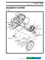
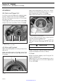
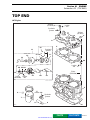
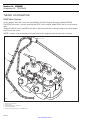
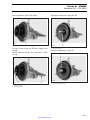
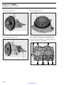
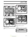
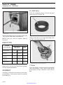
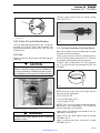
GSX Limited
www.SeaDooManuals.net
Legal deposit:
National Library of Quebec
National Library of Canada
All rights reserved. No parts of this manual may be
reproduced in any form without the prior written
permission of Bombardier Inc.
©
Bombardier Inc. 1997
Printed in Canada
*Registered trademarks of Bombardier Inc.
®
Loctite® is a trademark of Loctite Corporation
Snap-on® is a trademark of Snap-on Tools Corporation
Gelcote® is a trademark of Gelcote International
Limited
www.SeaDooManuals.net
TABLE OF CONTENTS
SECTION
SUBSECTION
PAGE
SAFETY NOTICE .......................................................................................................................................
II
01
ENGINE
01 - Magneto System................................................................
02 - Top End ..............................................................................
03 - Bottom End ........................................................................
04 - Exhaust System .................................................................
02
COOLING SYSTEM
01 - Circuit ................................................................................. 02-01-1
03
FUEL SYSTEM
01 - Carburetion ........................................................................ 03-01-1
04
ELECTRICAL SYSTEM
01 - Ignition and Charging Systems........................................... 04-01-1
02 - Starter................................................................................. 04-02-1
05
PROPULSION SYSTEM
01 - Drive System and Jet Pump............................................... 05-01-1
06
TECHNICAL DATA
01 - GSX Limited ....................................................................... 06-01-1
07
WIRING DIAGRAM ........................................................................................................................ 07-01-1
01-01-1
01-02-1
01-03-1
01-04-1
VOLUME
2
VOLUME
1 1997
www.SeaDooManuals.net
I
SAFETY NOTICE
SAFETY NOTICE
This manual was primarily published to be used by watercraft technicians trained by the manufacturer
who are already familiar with all service and maintenance procedures relating to Bombardier made SeaDoo watercraft.
Please note that the instructions will apply only if proper hand tools and special service tools are used.
It is understood that this manual may be translated into another language. In the event of any discrepancy, the English version shall prevail.
The content depicts parts and/or procedures applicable to the particular product at its time of manufacture. It does not include dealer modifications, whether authorized or not by Bombardier, after manufacturing the product.
The use of Bombardier parts is most strongly recommended when considering replacement of any component. Dealer and/or distributor assistance should be sought in case of doubt.
Torque wrench tightening specifications must be strictly adhered to. Locking devices (ex.: locking disk,
lock nut) must be installed or replaced with new ones, where specified. If the efficiency of a locking
device is impaired, it must be renewed.
This manual emphasizes particular information denoted by the wording and symbols;
◆
WARNING
Identifies an instruction which, if not followed, could cause serious personal injury including
possibility of death.
-
CAUTION
Denotes an instruction which, if not followed, could severely damage watercraft components.
NOTE: Indicates supplementary information needed to fully complete an instruction.
Although the mere reading of such information does not eliminate the hazard, your understanding of the
information will promote its correct use. Always use common shop safety practice.
This information relates to the preparation and use of Bombardier watercraft and has been utilized safely
and effectively by Bombardier Inc. However, Bombardier Inc. disclaims liability for all damages and/or
injuries resulting from the improper use of the contents. We strongly recommend that any services be
carried out and/or verified by a highly skilled professional technician. It is understood that certain modifications may render use of the watercraft illegal under existing federal, provincial and state regulations.
II
www.SeaDooManuals.net
Section 01 ENGINE
Subsection 01 (MAGNETO SYSTEM)
MAGNETO SYSTEM
0
947 Engine
9 N•m
(80 lbf•in) 2
8
Loctite 242
Anti-seize
lubricant
1
10
13 N•m
(115 lbf•in)
3
12
11
Loctite 242
13
9 N•m
(80 lbf•in)
9
Loctite 242
Loctite 648
115 N•m 6
(85 lbf•ft)
7
13 N•m
(115 lbf•in)
Loctite
648
4
5
F06D0IS
PARTS
www.SeaDooManuals.net
FLAT RATE
01-01-1
Section 01 ENGINE
Subsection 01 (MAGNETO SYSTEM)
DISASSEMBLY
1, Cover
Loosen screws no. 2. Remove engine magneto
cover.
F06D0KA
1
1. Remove pulse fitting
Turn engine manually until slot in crankshaft counterweight is aligned with the crankcase hole. Insert a M8 x 50 fixation screw to lock crankshaft.
F06D1RA
1
2
1. Cover
2. Screw
Remove oil pump shaft from flywheel nut.
F06B04A
CRANKSHAFT FIXATION SCREW (P/N 290 240 882)
F06D23A
1
1. Remove oil pump shaft
4,5, Rotor and Flywheel
To remove the rotor or the flywheel, the crankshaft must be locked.
Remove the pulse fitting beside the starter bracket
on the lower crankcase half.
F06D2AA
1. Crankshaft locked
01-01-2
www.SeaDooManuals.net
1
Section 01 ENGINE
Subsection 01 (MAGNETO SYSTEM)
If necessary, the magneto rotor can be removed
without the engine flywheel. Remove the 6
screws no. 7.
1
F06D0PA
F06D0LA
1
1. Puller
1. Screw
8,9, Stator and Trigger Coil
To remove the flywheel/rotor assembly, unscrew
nut no. 6 counterclockwise when facing it.
F06D0MA
Loosen screws no. 10 and no. 11 to remove the
stator and trigger coil from the engine magneto
cover.
1
1. Nut
1
F06D0NA
The flywheel is easily freed from crankshaft with
puller (P/N 420 976 235).
Install protective cap (P/N 290 877 414) to crankshaft.
Fully thread puller in engine flywheel.
1. Screws
CLEANING
Clean all metal components in a solvent.
-
CAUTION
Clean coils and magnet using only a clean
cloth.
Clean crankshaft taper and threads.
01-01-3
www.SeaDooManuals.net
Section 01 ENGINE
Subsection 01 (MAGNETO SYSTEM)
ASSEMBLY
8,9, Stator and Trigger Coil
Install the stator and trigger coil in engine magneto cover. Torque screws to 9 N•m (80 lbf•in).
Reinstall wiring harness bracket no. 12 using taptite screws no. 13.
Torque trigger coil screws no. 11 to 9 N•m (80 lbf•in).
Torque stator screws no. 10 to 13 N•m (115 lbf•in).
Apply Loctite 648 (green) on screws no. 7 retaining rotor to flywheel and torque screws in a crisscross sequence to 13 N•m (115 lbf•in).
Apply Loctite 242 (blue) on crankshaft taper.
F06D24A
1
1. Loctite 242 (blue) on crankshaft taper
F06D0NB
1
2
Install flywheel and make sure to align keyway
with the crankshaft Woodruff key.
Apply Loctite 242 (blue) on nut no. 6. Install nut
with lock washer and torque to 115 N•m (85
lbf•ft).
3
1. Torque to 9 N•m (80 lbf•in)
2. Taptite screws
3. Torque to 13 N•m (115 lbf•in)
-
4,5, Rotor and Flywheel
Never use any type of impact wrench.
Apply Loctite 648 (green) on mating surface of the
rotor no. 4.
When reinstalling rotor to flywheel, one of the
protrusion end of rotor must be aligned with hole
in flywheel.
1
2
CAUTION
Unlock crankshaft. Reinstall pulse fitting with
washer and torque to 23 N•m (17 lbf•ft).
1, Cover
Before installation, properly install O-ring no. 3 in
engine magneto cover.
Apply Loctite 767 anti-seize compound on screws
no. 2. Torque screws in a criss-cross sequence to
9 N•m (80 lbf•in).
F06D0OA
1. Protrusion
2. Hole
01-01-4
www.SeaDooManuals.net
Section 01 ENGINE
Subsection 02 (TOP END)
TOP END
0
947 Engine
34 N•m
(25 lbf•ft) 3
Loctite
242
Synthetic
grease
34 N•m
(25 lbf•ft)
4
1
5
16
Synthetic
grease
11
15 18
13
17
14
26
Loctite
242
22 23 24
3 N•m
(26 lbf•in)
12
Loctite
9 N•m
242
(80 lbf•in)
21
20
19
2
36
rollers 10
8
Synthetic
grease
7
9
8
6
F06D17S
PARTS
www.SeaDooManuals.net
FLAT RATE
01-02-1
Section 01 ENGINE
Subsection 02 (TOP END)
THEORY OF OPERATION
RAVE Valve System
On this engine, the RAVE valves are controlled by the Multi-Purpose Electronic Module (MPEM).
The MPEM measures 2 factors to control the RAVE valves: engine speed (RPM) and its rate of acceleration.
To open the RAVE valves, the MPEM activates a solenoid which directs the positive pressure from engine
crankcase to the valves.
NOTE: A check valve on the pressure line eliminates the negative pressure from the crankcase.
4
5
3
2
1
F06D16S
RAVE VALVE OPENED
1. Pulse from crankcase
2. Check valve
3. Positive pressure to solenoid
4. Solenoid activated
5. Positive crankcase pressure to RAVE valves
01-02-2
www.SeaDooManuals.net
Section 01 ENGINE
Subsection 02 (TOP END)
To close the RAVE valves, the MPEM deactivates the solenoid which blocks the crankcase positive pressure. The RAVE valves are opened to the atmosphere.
4
3
2
5
1
F06D16T
RAVE VALVE CLOSED
1. Pulse from crankcase
2. Check valve
3. Positive pressure blocked by the solenoid
4. Solenoid deactivated
5. RAVE valves are opened to atmosphere
01-02-3
www.SeaDooManuals.net
Section 01 ENGINE
Subsection 02 (TOP END)
DISASSEMBLY
Remove the compression spring no. 15.
11, RAVE Valve
Loosen Allen screws no. 12 each side of RAVE
valve.
F06D25A
1
1. Remove spring
Remove spring no. 16 retaining bellows no. 17 to
valve piston no. 18.
1
F06D0QA
1. Remove screws
Remove RAVE valve no. 11.
Remove the cover no. 13 of the valve by releasing
the spring no. 14.
;
WARNING
Firmly hold cover to valve base. The compression spring inside the valve is applying
pressure against the cover.
F06D0SA
1. Spring
F06D0RA
1
1. Spring
01-02-4
www.SeaDooManuals.net
1
Section 01 ENGINE
Subsection 02 (TOP END)
Remove bellows from valve piston.
Remove compression spring no. 22.
1
F06D0TA
1
A06D26A
1. Bellows removed from piston
Unscrew valve piston no. 18 from sliding valve
no. 19.
NOTE: Hold the sliding valve to prevent it from
turning.
1. Remove spring
Remove supporting ring no. 23.
1
F06D27A
F06D0TB
1
2
1. Remove supporting ring
1. Unscrew piston
2. Hold sliding valve
01-02-5
www.SeaDooManuals.net
Section 01 ENGINE
Subsection 02 (TOP END)
Remove O-ring no. 24.
Remove bellows no. 17.
1
F06D28A
1
F06D0VA
1. Remove O-ring
1. Remove bellows
Remove sliding valve no. 19.
1,2, Cylinder Head and Cylinder Block
Loosen cylinder head bolts no. 3 following the sequence shown in the next photo.
F06D0UA
6
4
F06D0WA
5
2
1
1. Remove sliding valve
1
3
7
UNTORQUING SEQUENCE FOR THE CYLINDER HEAD BOLTS
01-02-6
www.SeaDooManuals.net
Section 01 ENGINE
Subsection 02 (TOP END)
Loosen nuts no. 4 following the sequence shown
in the next photo.
5
2
4
7
F06D2BA
1
1. Remove studs
Remove cylinder block no. 2.
F06D29A
6
3
1
8
UNTORQUING SEQUENCE FOR THE NUTS
Remove cylinder head no. 1.
Remove cylinder head gasket no. 5.
1
F06D0ZA
1. Remove cylinder block
F06D0YA
NOTE: To ease removal, a plastic tip hammer can
be used.
Remove cylinder base gasket no. 6.
1
1. Remove gasket
7, Piston
Remove studs no. 25.
NOTE: Studs must be removed prior cylinder
block.
To remove piston circlip no. 8, insert a pointed
tool in piston notch then pry it out and discard.
;
WARNING
Always wear safety glasses when removing
piston circlips.
01-02-7
www.SeaDooManuals.net
Section 01 ENGINE
Subsection 02 (TOP END)
11, RAVE Valve
Install the supporting ring no. 23 with the bevel
side facing the O-ring no. 24.
1
F06D10A
1
1. Piston notch
F06D11A
To extract piston pin no. 9, use puller. Refer to the
1997 Sea-Doo Shop Manual for procedure.
NOTE: Piston pin features cageless bearing
(36 rollers).
1. Bevel facing the O-ring
There is only one way to insert the sliding valve
no. 19 in valve housing no. 21.
INSPECTION
ENGINE
MEASUREMENT
TOLERANCES
NEW PARTS
(min.) (max.)
WEAR
LIMIT
Cylinder Taper
N.A.
0.05 mm
(.002 in)
0.1 mm
(.004 in)
Cylinder Out
of Round
N.A.
0.008 mm
(.0003 in)
0.08 mm
(.003 in)
Piston/Cylinder Wall
Clearance
0.10 mm
(.004 in)
0.12 mm
(.005 in)
0.20 mm
(.008 in)
Ring/Piston Groove
Clearance
0.03 mm
(.001 in)
0.07 mm
(.003 in)
0.20 mm
(.008 in)
Ring End Gap
0.25 mm
(.010 in)
0.40 mm
(.016 in)
1.0 mm
(.039 in)
1
F06D12A
1. Sliding valve ridge toward housing groove
N.A.: Not Applicable
Refer to the 1997 Sea-Doo Shop Manual for proper measurement procedures.
ASSEMBLY
7, Piston
Install the pistons to the crankshaft connecting
rods with the letters “AUS” (over an arrow on the
piston dome) facing in direction of the exhaust
port.
Assembly is essentially the reverse of disassembly procedures. However pay particular attention
to the following.
01-02-8
www.SeaDooManuals.net
Section 01 ENGINE
Subsection 02 (TOP END)
To easily insert circlip no. 8, use circlip installer
(P/N 290 877 517).
1
AUS
A01C01A
TYPICAL — PISTON DOME SHOWN
1. Exhaust side
9,10, Piston Pin and Roller Bearing
To install roller bearing and piston pin, use piston
pin puller (P/N 290 877 094) used at removal. For
installation procedure, refer to the 1997 Sea-Doo
Shop Manual.
8, Circlip
Secure circlips no. 8 taking into consideration the
following.
-
CAUTION
To minimize the stress on the circlips, install
them so that their openings are located at 6
o’clock (at bottom). Always use new circlips.
At installation, take care not to deform them.
F06B01A
1
1. Circlip installer
1,2, Cylinder Head and Cylinder Block
Both the cylinder head and cylinder block are positioned with locating dowels.
There is only one way to install cylinder base gasket no. 6 and cylinder head gasket no. 5. They are
also properly positioned by locating dowels.
To easily slide cylinder block no. 2 over pistons
no. 7, install on piston ring compressor (P/N 290
876 965).
A01B1TA
1
1. Ring compressor
1
F06D18A
1. Circlip opening at 6 o’clock (at bottom)
◆
WARNING
Always wear safety glasses when installing
piston circlips.
NOTE: For each ring, make sure to align ring end
gap with piston locating pin.
Install studs no. 25.
Install cylinder block no. 2.
Install O-rings no. 26.
NOTE: The O-rings must be installed and properly
positioned in the cylinder block. The O-rings are
meant to dampen stud vibration.
Apply Loctite 242 (blue) on the threads of the cylinder block studs no. 25.
Apply Loctite 242 (blue) below head of cylinder
head bolts no. 3.
Apply synthetic grease on threads of cylinder
head bolts no. 3.
01-02-9
www.SeaDooManuals.net
Section 01 ENGINE
Subsection 02 (TOP END)
Torque bolts and nuts to 15 N•m (11 lbf•ft) as per following sequence in the next photo. Repeat the torquing sequence by retightening to 34 N•m (25 lbf•ft).
7 12
F06D0WB
13
1
4
10
8
9 5 11
3
2
14
6
15
TORQUING SEQUENCE
01-02-10
www.SeaDooManuals.net
Section 01 ENGINE
Subsection 03 (BOTTOM END)
BOTTOM END
0
947 Engine
30 mL
(1 oz)
Formula
XP-S
synthetic
oil
26
11
17
16
18
19
22
1
Synthetic
grease
Synthetic
grease
Loctite
242
20
21
Loctite 242
19
24
18
14
17
15
Loctite
242
15
Anti-seize
lubricant
9 N•m
7 (80 lbf•in)
8
Anti-seize
lubricant
9
Loctite
242
15
Loctite
242
9 N•m
Synthetic
(80 lbf•in)
grease Loctite
648
Loctite
242
Synthetic
grease
Loctite
242
Loctite
518
6
11
23
15
1
Synthetic
grease
2
Loctite 518
Synthetic grease
13
23 N•m
(17 lbf•ft)
F06D19S
10
25
Loctite
518
Synthetic
grease
Loctite
518
12
13 23 N•m
(17 lbf•ft)
12
Synthetic grease
PARTS
www.SeaDooManuals.net
5
115 N•m
(85 lbf•ft)
4
23 N•m
3
(17 lbf•ft)
Loctite 518
Synthetic grease
13 23 N•m
(17 lbf•ft)
40 N•m
(30 lbf•ft)
FLAT RATE
01-03-1
Section 01 ENGINE
Subsection 03 (BOTTOM END)
DISASSEMBLY
The following components should be removed
prior to opening bottom end:
– magneto cover
– magneto flywheel
– starter
Loosen bolt no. 5 retaining the PTO flywheel to
the crankshaft.
1, Seal
If a crankshaft end seal has to be replaced, bottom end must be opened.
2, PTO Flywheel
Lock the crankshaft using the same procedure for
the magneto flywheel removal. Refer to ENGINE
01-01.
Loosen the 6 Allen screws no. 4 retaining the
coupling flange no. 3 to the PTO flywheel.
F06D1BA
1
1. Bolt
Remove the PTO flywheel no. 2 using puller
(P/N 290 976 237).
F06B02A
F06D1AA
1
1. Allen screw (6)
Remove the coupling flange no. 3.
Install puller to PTO flywheel. Insert 6 M8 x 30
screws (P/N 290 940 481) through puller holes
and tighten screws in PTO flywheel to extract it
from crankshaft.
01-03-2
www.SeaDooManuals.net
Section 01 ENGINE
Subsection 03 (BOTTOM END)
6, Starter Drive Assembly
10, Reed Valve
Loosen 2 Allen screws no. 7 retaining starter
drive cover no. 8.
Remove both carburetor flanges.
F06D0JA
1
1. Carburetor flange
F06D1CA
2
1
Remove reed valves from crankcase.
1. Cover
2. Allen screw
11, Crankcase
Remove starter drive cover no. 8 and spring
no. 9.
Remove starter drive assembly no. 6.
Place engine upright on crankcase magneto side.
F06D1DA
1. Starter drive assembly
F06D1QA
1
Loosen crankcase bolts no. 12 and no. 13 starting from center to the outside.
Put engine back on a trestle and remove the upper crankcase half.
Insert a pry bar between crankcase lugs to separate halves. Be careful not to damage precision
machined surfaces.
01-03-3
www.SeaDooManuals.net
Section 01 ENGINE
Subsection 03 (BOTTOM END)
6
1
3
5
4
2
F06B03A
1.
2.
3.
4.
5.
6.
F06D1FA
1
6
Puller (P/N 420 877 635)
Protective cap (P/N 290 877 414)
Distance ring (P/N 290 876 569)
Ring (P/N 290 977 480)
Ring halves (P/N 290 876 330)
Screw (P/N 290 940 755)
NOTE: To facilitate ring or distance ring installation, lubricate their inside diameters.
Or, use a bearing extractor such as Proto no. 4332
and a press to remove 2 bearings at a time.
1. Separate halves by prying at provided lugs (both sides)
Remove crankshaft and counterbalance shaft.
14, Crankshaft
NOTE: Do not needlessly remove crankshaft
bearings.
Remove end seals no. 1.
1
2
F01D1PA
TYPICAL
1. Press bearings out
2. Bearing extractor
F06D1GA
16, Counterbalance Shaft
1
1. End seal (MAG side)
To remove end bearings no. 15 from crankshaft,
use the following tools:
NOTE: Do not needlessly remove counterbalance
shaft bearings.
Use a press to remove counterweights no. 17
and bearings no. 18.
-
CAUTION
There is no woodruff key to position the
counterweights. An index mark must be
traced to retain the proper position of the
counterweight.
01-03-4
www.SeaDooManuals.net
Section 01 ENGINE
Subsection 03 (BOTTOM END)
10, Reed Valve
Check reed valve petals no. 24 for cracks or other
defects. The reed petals must lie completely flat
against the reed valve body no. 25. To check, hold
against light.
F06D1HA
1
1. Trace an index mark
Remove seals no. 19.
Remove bearing no. 20 and washer no. 21.
Use a press to remove gear no. 22.
INSPECTION
1
F06D1JA
Visually inspect parts for corrosion damage.
Inspect plane surfaces for warpage. Small deformation can be corrected by grinding surface with
a fine sandpaper.
Inspect bearings. Check for scoring, pitting, chipping or other evidence of wear.
Check bearing no. 23 of starter drive assembly
no. 6 in crankcase.
1. No play
In case of a play, turn reed petals upside down
and recheck. If there is still a play, replace petals.
Check perfect condition of rubber coating on reed
valve body.
Check stopper distance from center of reed valve
block.
A
F06D1IA
1
F06D1EA
1. Bearing of starter drive assembly
A. 13 ± 0.25 mm (.512 ± .010 in)
NOTE: Distance should be the same on both
sides.
01-03-5
www.SeaDooManuals.net
Section 01 ENGINE
Subsection 03 (BOTTOM END)
Bent stopper as required to obtain the proper distance.
2
14, Crankshaft
Refer to the 1997 Sea-Doo Shop Manual for complete procedure of crankshaft inspection.
ASSEMBLY
15, Bearing
Apply Loctite 767 anti-seize on part of crankshaft
where bearings fit.
Prior to installation, place bearings into a container
filled with oil, previously heated to 75°C (167°F).
This will expand bearings and ease their installations.
To properly position the outer PTO and MAG bearings, a distance gauge should be temporarily installed against the inner bearing. Slide the outer
bearing until stopped by the distance gauge, then
remove it.
F06D1KA
1
1
1. Outer bearing drive pins on this side
2. Inner bearing drive pins on this side
Seals no. 1 are positioned with the outer lip in the
crankcase recess.
1
1
F01B0HA
1. Distance gauge
1, Seal
At seal assembly, apply a light coat of synthetic
grease on seal lips.
F06D1LA
14, Crankshaft
Install crankshaft in crankcase lower half.
Pay attention to properly position drive pins of
center and outer bearings. Drive pins of outer
bearings must be on the opposite side of the
counterbalance shaft. Drive pins of inner bearings
must be on the same side as the counterbalance
shaft.
1. Seal lip in crankcase recess
16, Counterbalance Shaft
Install bearing no. 20 and washer no. 21.
When installing seals no. 19, apply a light coat of
synthetic grease on seal lips.
Place bearings no. 18 into a container filled with
oil, previously heated to 75°C (167°F). This will expand bearings and ease their installation.
Reinstall counterweights no. 17 using a press and
take care to align index marks previously traced.
01-03-6
www.SeaDooManuals.net
Section 01 ENGINE
Subsection 03 (BOTTOM END)
Install the counterbalance shaft in crankcase lower half. Make sure to properly index crankshaft
and counterbalance shaft by aligning marks of
gears.
1
F06D1OA
1. Seal in place
11, Crankcase
F06D1MA
1
1. Marks must be aligned
Properly position bearing no. 20 and washer
no. 21.
F06D1NA
Crankcase halves are factory matched and therefore, are not interchangeable or available as single
halves.
Make sure all locating dowels are in place.
1 2
F06D1PA
1
1. Dowel
1. Bearing
2. Washer in crankcase groove
Place seals no. 19 in their respective positions.
Prior to joining crankcase halves, apply a light coat
of Loctite 518 on mating surfaces. Do not apply in
excess as it will spread out inside crankcase.
NOTE: On aluminum material it is recommended
to use Loctite Primer N to reduce curing time and
increase gap filling capability. Refer to manufacturer’s instructions.
Position crankcase halves together.
01-03-7
www.SeaDooManuals.net
Section 01 ENGINE
Subsection 03 (BOTTOM END)
Apply synthetic grease below head of bolts
no. 12 and no. 13.
Apply also Loctite 518 on threads of bolts no. 12
and no. 13.
Torque crankcase bolts to 12 N•m (9 lbf•ft) as per
following sequence. Repeat procedure, retightening all bolts to 23 N•m (17 lbf•ft).
9
7
14
3
1
16
5
18
11
20
10
21
8
19
2
F06D32A
13
2
1. Handle
2. Pusher
17
6
2, PTO Flywheel
Apply Loctite 242 (blue) on bolt no. 5.
Torque bolt no. 5 to 115 N•m (85 lbf•ft).
Apply Loctite 648 on mating surface of PTO flywheel and coupling flange.
22
12
F06D1QB
As a final step, torque only the M10 x 73,5 bolts
no. 12 to 40 N•m (30 lbf•ft) as per following sequence.
10
7
8
3
4
1
2
5
11
6
To install bearing no. 23 of starter drive assembly,
use pusher (P/N 290 876 502) and handle (P/N 290
877 650).
1
4
15
9
23, Bearing
26, Filler Plug
When engine assembly is completed, add 30 mL
(1 oz) of Formula XP-S synthetic oil to the counterbalance shaft gear through the crankcase filler
plug.
F06D2CA
12
1
1. Remove filler plug and add 30 mL (1 oz) of injection oil
F06D1QC
01-03-8
www.SeaDooManuals.net
Section 01 ENGINE
Subsection 04 (EXHAUST SYSTEM)
EXHAUST SYSTEM
0
GENERAL
To enhance performance and reduce noise level,
the GSX Limited is equipped with a new plastic
made resonator.
1
1
F06E08A
1. Water inlet hose
Disconnect at the tuned pipe head the water supply hose of the water flow regulator valve.
F06D13A
1. Resonator
REMOVAL
Tuned Pipe
Remove seat.
Remove air vent tube support from body opening.
Disconnect water inlet hose at tuned pipe head.
F06E09A
1
1. Water supply hose for the regulator valve
01-04-1
www.SeaDooManuals.net
Section 01 ENGINE
Subsection 04 (EXHAUST SYSTEM)
Disconnect the water injection hose at tuned pipe
head.
Loosen clamp retaining exhaust hose to tuned
pipe cone.
1
1
F06E0AA
F06D14A
1. Water injection hose
1. Loosen clamp
Disconnect the water bleed hose.
Loosen and remove clamp retaining tuned pipe
head to tuned pipe cone.
F06E0BA
1
1. Water bleed hose
F06D1SA
1
1. Loosen and remove clamp
01-04-2
www.SeaDooManuals.net
Section 01 ENGINE
Subsection 04 (EXHAUST SYSTEM)
Loosen Allen screw of carburetor bracket.
F06D2DA
Loosen bolt of tuned pipe head above the engine
magneto.
1
1
F06D1UA
1. Loosen Allen screw
Loosen Allen screws and nut at tuned pipe flange.
1. Remove bolt
Remove tuned pipe head.
Loosen bolt of tuned pipe cone beside the engine
water outlet hose.
F06D1TA
1
1. Tuned pipe flange
F06D1VA
1
1. Loosen bolt
Remove tuned pipe cone.
Exhaust Manifold
Remove tuned pipe head (if not removed).
Remove 8 Allen screws with lock washers then
withdraw exhaust manifold.
01-04-3
www.SeaDooManuals.net
Section 01 ENGINE
Subsection 04 (EXHAUST SYSTEM)
Muffler
INSTALLATION
Disconnect front exhaust hose (if tuned pipe is
not removed).
Disconnect top exhaust hose from muffler.
Disconnect hoses of the water flow regulator
valve (if tuned pipe is not removed).
Disconnect retaining strap.
Installation is essentially the reverse of removal
procedures. However, pay particular attention to
the following.
1
F06D1WA
Exhaust Manifold
Make sure new gaskets are properly positioned
prior finalizing manifold installation.
Apply synthetic grease on threads of Allen
screws.
Install and hand tighten Allen screws as per following photo.
2
1. Disconnect hoses (if tuned pipe is not removed)
2. Disconnect strap
Remove VTS motor. Refer to 1997 Sea-Doo Shop
Manual, PROPULSION SYSTEM 08-05.
Remove muffler.
1
F06D1YA
2
1
1. M10 x 60 Allen screws
2. M10 x 110 Allen screws
Resonator
Torque Allen screws to 24 N•m (17 lbf•ft) as per
following illustrated sequence. Repeat the procedure, retightening Allen screws to 40 N•m
(30 lbf•ft).
Remove battery.
;
WARNING
Always disconnect battery cables exactly in
the specified order, BLACK negative cable
first.
8
2
3
6
Disconnect exhaust hose.
Remove resonator.
REPAIR
Tuned Pipe
Refer to the 1997 Sea-Doo Shop Manual, section
ENGINE 03-08 for procedure.
F06D1YB
7
01-04-4
www.SeaDooManuals.net
4
1
5
Section 01 ENGINE
Subsection 04 (EXHAUST SYSTEM)
Tuned Pipe
Make sure to install the sealing ring on tuned pipe
cone if it was removed.
Apply a thin layer of heat resistant sealant
(P/N 413 709 200) all around sealing ring.
Ensure rubber bushings and sleeves are not damaged and are properly installed into tuned pipe
supports.
-
Torque bolt of tuned pipe head above the engine
magneto to 25 N•m (18 lbf•ft).
CAUTION
Damage to bushings and or sleeves will
eventually cause stress to tuned pipe and
may cause cracking.
Make sure that gasket is properly located on exhaust manifold prior to finalizing tuned pipe head
installation.
Apply Loctite 242 (blue) on bolts, Allen screws
and nut.
1
F06D1UA
1. Torque bolt to 25 N•m (18 lbf•ft)
Torque bolt of tuned pipe cone beside the engine
water outlet hose to 25 N•m (18 lbf•ft).
Tune Pipe Torquing Sequence
Hand tighten all fasteners before torquing any of
them.
Torque Allen screws and nut at tuned pipe head
flange to 25 N•m (18 lbf•ft).
F06D1VA
1
1. Torque bolt to 25 N•m (18 lbf•ft)
1
F06D1TA
1. Torque Allen screws and nut to 25 N•m (18 lbf•ft)
01-04-5
www.SeaDooManuals.net
Section 01 ENGINE
Subsection 04 (EXHAUST SYSTEM)
Torque clamp of tuned pipe head to 14 N•m
(10 lbf•ft).
Torque exhaust hose clamp of tuned pipe cone to
4 N•m (35 lbf•in).
1
F06D1SA
1
F06D14A
1. Torque clamp to 14 N•m (10 lbf•ft)
1. Torque clamp to 4 N•m (35 lbf•in)
As a final step, torque Allen screws and nut at
tuned pipe head flange to 40 N•m (30 lbf•ft).
Muffler
Torque exhaust hose clamps of muffler to 4 N•m
(35 lbf•in).
Resonator
Torque exhaust hose clamps of resonator to
3 N•m (27 lbf•in).
F06D1TA
1
1. Torque Allen screws and nut to 40 N•m (30 lbf•ft)
F06D1ZA
1
1. Torque clamps to 3 N•m (27 lbf•in)
01-04-6
www.SeaDooManuals.net
Section 02 COOLING SYSTEM
Subsection 01 (CIRCUIT)
CIRCUIT
0
947 Engine Cooling System
As with other models, the water supply is provided by a pressurized area in the jet pump between
the impeller and venturi.
Water is directed to the water jacket of the tuned
pipe head.
After water has circulated in the cylinder-block
water jackets, it is directed in the 1 piece cylinder
head which features improved combustion chamber and spark plug cooling.
F06D21A
Water exits cylinder head water jackets through
an outlet fitting.
1
F06E08A
1. Water inlet hose
Water circulates in the jackets of the tuned pipe
head and the exhaust manifold. It is consequently
pre-heated by the exhaust system.
Then, water enters the cylinder-block water jackets through passages located above and below
exhaust ports.
F06E05A
1
1. Engine water outlet
F06D20A
1
Water circulates in the water outlet hose and is
expelled out of the cooling system through a fitting located in the jet pump support on the transom of the watercraft.
Draining of the cooling system is accomplished by
the drain hose connected to a fitting at the bottom
of the cylinder-block, on tuned pipe side.
1. Water passages
02-01-1
www.SeaDooManuals.net
Section 02 COOLING SYSTEM
Subsection 01 (CIRCUIT)
Bleeding of the cooling system is accomplished
by the bleed hose located at the uppermost point
of the circuit at the tuned pipe. The bleed hose
also serves as the Cooling System Indicator (CSI).
Water Flow Regulator Valve
The water supply of the water flow regulator is
provided by the water jacket of the tuned pipe
head.
1
F06E0BA
1
F06E09A
1. Bleed hose
1. Water supply of the water flow regulator valve
-
CAUTION
When servicing the hull, always rotate watercraft CLOCKWISE (seen from rear). Rotating the watercraft on the opposite side could
allow residual water in the tuned pipe to enter the engine.
The lower hose of the valve is the water supply
and the upper hose is the regulated injection water for the tuned pipe.
2
max. 90 °
1
F06E0CA
3
1. Water supply from tuned pipe water jacket
2. Regulated injection water to the tuned pipe
3. Muffler
F06L0GA
TYPICAL
02-01-2
www.SeaDooManuals.net
Section 02 COOLING SYSTEM
Subsection 01 (CIRCUIT)
Regulated water is injected in the tuned pipe by a
calibrated fitting.
F06E0AA
1
1. Injection fitting
02-01-3
www.SeaDooManuals.net
Section 03 FUEL SYSTEM
Subsection 01 (CARBURETION)
CARBURETION
0
AIR INTAKE SILENCER
The air intake silencer is a molded piece and it can
not be opened.
It contains a new flame arrester, which can not be
removed.
1
F06F06A
2
1. Fuel inlet hose
2. Fuel outlet hose
F06D22A
1
1. Air intake silencer
FUEL ACCELERATOR PUMP
General
The carburetors are equipped with a fuel accelerator pump.
The fuel accelerator pump is mounted on the
magneto side carburetor. It is linked to the throttle
valve via a linkage.
A metering jet in the fuel inlet hose controls fuel
supply to the pump.
A check valve on the fuel outlet hose prevents air
from entering in the system.
Using a suitable pump gauge tester, perform the
following test proceeding as follows:
– Install pump gauge tester (P/N 295 000 083) on
inlet nipple.
– Obstruct outlet nipple with a finger and hold
while pumping.
– Pump tester until it reaches 28 kPa (4 PSI).
Inspection
Disconnect inlet and outlet hoses from accelerator pump nipples.
F06F07A
1
2
3
1. Pump gauge tester
2. Hose installed to inlet nipple
3. Outlet nipple obstructed
Diaphragm must stand pressure for 10 seconds.
If pressure drops, replace diaphragm.
03-01-1
www.SeaDooManuals.net
Section 03 FUEL SYSTEM
Subsection 01 (CARBURETION)
Verify accelerator pump check valves operation as
follows:
Connect a clean plastic tubing to the valve inlet
nipple and alternately apply pressure and vacuum.
The check valve should release with pressure and
hold under vacuum.
◆
WARNING
Some fuel may be present in fuel pump.
NOTE: Injectors are also equipped with check
valves.
Adjustment
Ensure throttle cable is properly adjusted and idle
speed is set at 1500 RPM in water.
With the engine not running, start adjustment by
loosening adjustment screw until there is a small
gap between lever tab and pump plunger.
F06F06C
1
2
1. Turn adjustment screw
2. Small gap here
F06F08A
1
TYPICAL
1. Apply pressure and vacuum at inlet nipple
Repeat the same procedure for the injector.
Turn adjustment screw clockwise until lever tab
touches plunger.
Then, turn adjustment screw an additional 1/4
turn clockwise. The adjustment is now completed.
1
Accelerator Pump Verification
With engine stopped, remove air intake silencer,
then activate throttle lever and look through carburetor venturi to ensure accelerator pump is injecting fuel. Reinstall air intake silencer.
NOTE: Activate throttle lever only a few times to
prevent engine flooding.
Accelerator Pump Lubrication
Lubricate pump plunger, roller and cam with synthetic grease (P/N 293 550 010) and roller shaft
with BOMBARDIER LUBE (P/N 293 600 016).
F04F0JB
2
TYPICAL
1. Apply pressure and vacuum through disconnected hose
2. Injector
03-01-2
www.SeaDooManuals.net
Section 03 FUEL SYSTEM
Subsection 01 (CARBURETION)
1
F06F06B
2
1
TYPICAL
1. Apply synthetic grease to plunger
2. Apply BOMBARDIER LUBE on roller shaft
F06F09A
1. Throttle position switch
BN-46I CARBURETORS
On these carburetors, diaphragms are either
opened to the atmosphere or to the air intake silencer, depending upon throttle position.
The advantage of this system is to keep the right
air/fuel ratio on the entire RPM’s range of the engine.
To transfer the venting of the diaphragms, 3 main
components are used:
– throttle position switch
– amplifier
– solenoid
The throttle position switch is built-in the throttle
cable. Its purpose is to signal the amplifier.
The amplifier boost the signal received from the
throttle position switch and activates the solenoid. The switch is mounted opposite to the oil
injection reservoir.
1
F06H1OA
1. Amplifier
03-01-3
www.SeaDooManuals.net
Section 03 FUEL SYSTEM
Subsection 01 (CARBURETION)
The solenoid is responsible for changing the venting position of the carburetors. The solenoid is located on the body, on left side.
1
3
2
1
F06F0BB
SOLENOID ACTIVATED
1. Inlet (carburetor diaphragms)
2. Outlet to atmosphere blocked
3. Outlet to air intake silencer opened
F06F0BA
TYPICAL
1. Solenoid
Up to 80% throttle opening, the solenoid is not
activated and the diaphragms of the carburetors
are opened to atmosphere.
1
3
When the diaphragms are opened to the air intake
silencer, the resulted vacuum moves the diaphragms, slightly leaning the mixture of the carburetors.
Inspection
2
Throttle Position Switch
Disconnect the 3-wire connector housing from
the amplifier.
Using a 12 V battery and jumpers, connect the
POSITIVE to the connector housing RED wire
(POSITION A) and the negative to the connector
housing BLACK wire (POSITION B).
Using a voltmeter, connect the positive probe to
the RED wire (POSITION A) of the connector
housing and the negative probe to the BLUE wire
(POSITION C) of the connector housing.
The voltmeter should indicate 0 Volt.
Depress the throttle lever progressively. At 80%
to full throttle opening, the voltmeter should indicate the battery voltage. If not, replace throttle cable.
F06F0BB
SOLENOID NOT ACTIVATED
1. Inlet (carburetor diaphragms)
2. Outlet to atmosphere
3. Outlet to air intake silencer blocked
From 80% to full throttle opening, the throttle position switch signals the amplifier. The amplifier
boost the signal to activate the solenoid.
The solenoid transfers the venting of the regulator
diaphragms from atmosphere to the air intake silencer (vacuum).
Amplifier
First, ensure the throttle position switch is in good
condition.
Disconnect the wiring harness (PURPLE and
BLACK wires) of the amplifier.
Using a 12 V battery and jumpers, connect the
POSITIVE to the amplifier PURPLE wire and the
NEGATIVE to the amplifier BLACK wire.
03-01-4
www.SeaDooManuals.net
Section 03 FUEL SYSTEM
Subsection 01 (CARBURETION)
Disconnect the wiring harness of the solenoid.
Using a voltmeter, connect the positive probe to
the PURPLE/BLUE wire and the negative probe to
the BLACK/BLUE wire.
With the safety lanyard removed, depress
start/stop button to activate the MPEM timer.
The voltmeter should indicate 0 Volt.
Depress the throttle lever progressively. At 80%
to full throttle opening, the voltmeter should indicate the battery voltage. If not, replace the amplifier.
Connect a 12 V battery to solenoid terminals.
Apply pressure to the inlet nipple. Air should be
released to the outlet nipple leading to the air intake silencer.
1
2
Solenoid
Disconnect the wiring harness of the solenoid.
Apply pressure to the inlet nipple. Air should be
released to the outlet nipple for the atmosphere.
1
2
F06F0BD
SOLENOID ACTIVATED
1. Apply pressure to inlet nipple
2. Air should be released here
F06F0BC
SOLENOID NOT ACTIVATED
1. Apply pressure to inlet nipple
2. Air should be released here
03-01-5
www.SeaDooManuals.net
Section 04 ELECTRICAL SYSTEM
Subsection 01 (IGNITION AND CHARGING SYSTEMS)
IGNITION AND CHARGING SYSTEMS 0
The ignition and charging systems of the 947 engine are of the same type as the 787 engine.
The high amperage/voltage components (ignition
coil and solenoid) are located into a rear electrical
box.
To access the rear electrical box, remove seat and
vent tube support.
1
Digitally Encoded Security System
F06E06A
1. Rear electrical box
The other components are integrated to the MultiPurpose Electronic Module (MPEM).
On this model, the MPEM is a Nippondenso unit,
which features a built in rectifier/regulator.
F06H0SA
The MPEM is directly powered by the battery. It
has a micro-processor inside of its sealed case.
The MPEM is responsible of the following electrical functions:
– interpreting information
– distributing information
– start/stop function
– timer
– Digitally Encoded Security System
– ignition
– engine rev limiter
– rectifying AC to DC
– regulating charging current
Fuses are directly mounted onto the MPEM.
To test the rectifier/regulator, proceed the same
way as explained in the 1997 Sea-Doo Shop Manual (P/N 219 100 048).
For a stronger and more reliable signal of the safety lanyard, the amplifier of the throttle position
switch is also used for the Digitally Encoded Security System.
When installing the safety lanyard cap on the
switch, the amplifier boosts the signal sent to the
MPEM.
1
1. Nippondenso Multi-Purpose Electronic Module
04-01-1
www.SeaDooManuals.net
Section 04 ELECTRICAL SYSTEM
Subsection 02 (STARTER)
STARTER
0
GENERAL
DISASSEMBLY
The 947 engine is equipped with a MITSUBA 12 V
starter.
The starter is coupled to the drive assembly,
which contains the overrunning clutch and gear
reduction.
To remove the drive assembly, the engine magneto cover must be removed.
Locate index marks on yoke and end covers.
1
REMOVAL
Remove seat.
Remove air vent tube support.
Remove air intake silencer.
Disconnect the BLACK negative battery cable.
;
F06H1FA
1. Index marks
Loosen through bolts.
WARNING
1
Always disconnect battery cables exactly in
the specified order.
Disconnect the RED positive battery cable.
Disconnect starter cables and loosen Allen
screws retaining starter bracket to engine.
3
2
F06H1GA
1. Through bolts
Remove end cover and gasket on armature shaft
side.
F06H1EA
1
3
1. Positive starter cable
2. Negative starter cable
3. Allen screw
Remove starter.
04-02-1
www.SeaDooManuals.net
Section 04 ELECTRICAL SYSTEM
Subsection 02 (STARTER)
Remove thrust washer from armature shaft.
Release brush wires of yoke from brush holder.
Remove brush holder.
1
1
F06H1HA
1. Thrust washer
F06H1KA
Remove the other end cover and gasket.
Remove the 3 washers from armature shaft.
1. Remove brush holder
To remove brushes from yoke, loosen nut and remove washers.
1
1
F06H1IA
1. Washers
Remove armature.
F06H1LA
1. Loosen nut and remove washers
Remove brushes.
F06H1JA
1
1. Pull armature shaft
04-02-2
www.SeaDooManuals.net
Section 04 ELECTRICAL SYSTEM
Subsection 02 (STARTER)
To remove bearing and seal in end cover, release
tabs of retainer.
Install the 3 washers onto armature shaft, with
the thicker one in the middle.
1
1
F06H1MA
1. Retainer
F06H1NA
INSPECTION
1. Thick washer in the middle
For parts inspection, refer to the 1997 Sea-Doo
Shop Manual, ELECTRICAL SYSTEM 07-04.
ASSEMBLY
Reverse the order of disassembly to reassemble
starter. However, pay particular attention to the
following.
Install new O-rings and gaskets.
Insert thrust washer onto armature shaft with the
non-metallic surface facing the end cover.
F06H1HA
When installing end covers to yoke, align index
marks.
Apply Loctite 271 (red) on through bolts and
torque to 6 N•m (53 lbf•in).
Apply Loctite 242 (blue) on Allen screws of starter
bracket and torque to 10 N•m (89 lbf•in).
1
1. Non-metallic surface on this side
04-02-3
www.SeaDooManuals.net
Section 04 ELECTRICAL SYSTEM
Subsection 02 (STARTER)
STARTER SPECIFICATION
Nominal output
0.8 kW
Voltage
12 V
Rated time
30 seconds
Rotation
Counterclockwise (viewed from pinion side)
Weight
1.7 kg (3.7 lb)
Performance specification at 20°C (68°F)
Battery
No load
10.9 V
45 A max.
8600 RPM
Load
9V
120 A max.
5350 RPM
Stall
2.25 V
390 A max.
0 RPM
12 V, 19 Ah
04-02-4
www.SeaDooManuals.net
Section 05 PROPULSION SYSTEM
Subsection 01 (DRIVE SYSTEM AND JET PUMP)
DRIVE SYSTEM AND JET PUMP
0
DRIVE SYSTEM
JET PUMP
Seal Carrier and Bearing
For performance improvement, the GSX Limited
features a new jet pump with an impeller diameter of 155.6 mm (6-1/8 in).
The jet pump housing and venturi are made of aluminum.
Servicing the jet pump is identical as with the other models. For disassembly, inspection and assembly procedures, refer to the 1997 Sea-Doo
Shop Manual, section 08-02.
The drive system is equipped with a seal carrier
and a needle bearing.
Seal carrier should be lubricated with synthetic
grease every 10 hours.
F06I03A
1
1. Grease seal carrier
For disassembly and assembly procedures of the
seal carrier, refer to the 1997 Sea-Doo Shop Manual,
section 08-03.
05-01-1
www.SeaDooManuals.net
Section 06 TECHNICAL DATA
Subsection 01 (GSX LIMITED)
GSX LIMITED
0
ENGINE
GSX Limited (5625)
Engine type
Bombardier-Rotax 947
Induction type
Exhaust system
Reed valve
Type
Water cooled, water injected with regulator
Water injection fitting (head)
3.5 mm (.139 in)
Water injection fitting (cone)
N.A.
Water injection fitting
(muffler)
3.5 mm (.139 in)
Exhaust valve
Rotax Adjustable Variable Exhaust (RAVE)
Starting system
Lubrication
Electric start
Fuel/oil mixture
VROI (Variable Rate Oil Injection)
Oil injection pump
Direct driven
Oil type
BOMBARDIER-ROTAX FORMULA XP-S
Synthetic injection oil (or equivalent synthetic oil)
Number of cylinders
Bore
2
Standard
88 mm (3.465 in)
First oversize
88.25 mm (3.474 in)
Second oversize
N.A.
Stroke
78.20 mm (3.079 in)
Displacement
951.2 cm³ (58 in³)
Corrected compression ratio
6.0: 1
Cylinder head warpage (maximum)
N.A.
Piston ring type and quantity
2 Semi-trapez
Ring end gap
New
Ring piston groove
New
0.25 - 0.40 mm (.010 - .016 in)
Wear limit
1.00 mm (.039 in)
0.025 - 0.070 mm (.001 - .003 in)
Wear limit
Piston/cylinder wall
clearance
0.2 mm (.008 in)
New (minimum)
0.110 mm (.0043 in)
Wear limit
0.200 mm (.008 in)
Cylinder taper (maximum)
0.100 mm (.004 in)
Cylinder out of round (maximum)
0.080 mm (.003 in)
Connecting rod big end axial
play
New
0.311 - 0.678 mm (.012 - .027 in)
Wear limit
Crankshaft deflection
1.2 mm (.047 in)
MAG side: 0.050 mm (.002 in); PTO side: 0.030 mm (.001 in)
Connecting rod/crankshaft
pin radial clearance
New
Connecting rod/piston pin
radial clearance
New
0.017 - 0.034 mm (.0007 - .0013 in)
Wear limit
0.050 mm (.002 in)
0.003 - 0.012 mm (.00012 - .00047 in)
Wear limit
0.015 mm (.00059 in)
ADDITIONAL INFORMATION:
06-01-1
www.SeaDooManuals.net
Section 06 TECHNICAL DATA
Subsection 01 (GSX LIMITED)
ELECTRICAL
GSX Limited (5625)
Magneto generator output
180 W @ 6000 RPM
or 5.0 A @ 6000 RPM
Ignition system type
Spark plug
Digital DC-CDI
Make and type
Gap
Ignition timing
(BTDC)
NGK BR8ES
0.5 - 0.6 mm (.020 - .024 in)
mm (in)
3.60 (.142)
Degrees
22° ± 1 @ 3500 RPM
Generating coil
N.A.
0.1 - 1 Ω
Battery charging coil
190 - 300 Ω
Trigger coil
Ignition coil
Primary
0.33 - 0.62 Ω
Secondary
8.4 - 15.6 k Ω
Engine rev limiter setting
7200 (± 50) RPM
Battery
Fuse
(Yuasa/Exide) 12 V, 19 A•h
Starting system
5A
Charging system
2 x 15 A
VTS system
7.5 A
ADDITIONAL INFORMATION:
CARBURETION
Carburetor
GSX Limited (5625)
Type
Mikuni BN-46I (diaphragm)
Fuel acceleration pump
Quantity
2
Main jet
160 MAG
162.5 PTO
Pilot jet
80
Spring
Adjustment
130 g (or 95 g with 1.75 mm aluminum shim)
Low-speed screw
1-3/4 turn ± 1/4
High-speed screw
0
Idle speed (in water)
1500 RPM
Idle speed (out of water)
Fuel
Type
3000 RPM
Regular unleaded gasoline
Minimum octane no.
Fuel return line orifice
87
MAG and PTO: 0.8 mm (.031 in)
ADDITIONAL INFORMATION:
06-01-2
www.SeaDooManuals.net
Section 06 TECHNICAL DATA
Subsection 01 (GSX LIMITED)
COOLING
GSX Limited (5625)
Type
Open circuit — Direct flow from jet propulsion unit
Thermostat
None
Monitoring beeper setting
86-94°C (187-201°F)
ADDITIONAL INFORMATION: Do not mix different brands or oil types.
PROPULSION
GSX Limited (5625)
Propulsion system
Bombardier Formula Pump
Jet pump type
Axial flow single stage
Impeller rotation (seen from rear)
Counterclockwise
Transmission
Direct drive
Coupling type
Crown splines
Oil type
SEA-DOO JET PUMP SYNTHETIC
POLYOLESTER OIL 75W90 GL5
Steering nozzle pivoting angle
20°
Minimum required water level
90 cm (35 in)
Drive shaft deflection (maximum)
0.5 mm (.020 in)
Impeller outside diameter
Impeller/wear ring
clearance
155.6 mm (6.126 in)
New
0.0 - 0.4 mm (.000 - .016 in)
Wear limit
Impeller shaft end play (new)
1.00 mm (.040 in)
0.12 - 0.54 mm (.005 - .021 in)
Impeller shaft side play
0.05 mm (.002 in)
Impeller pitch/material
Progressive pitch 9° - 21°/stainless steel
ADDITIONAL INFORMATION: Do not mix different brands or oil types.
DIMENSIONS
GSX Limited (5625)
Number of passenger (driver incl.)
2
Overall length
267 cm (105 in)
Overall width
116 cm (45.7 in)
Overall height
94 cm (37 in)
Dry weight
237 kg (523 lb)
Load limit (passenger and 10 kg (22 lb) luggage)
159 kg (351 lb)
ADDITIONAL INFORMATION:
06-01-3
www.SeaDooManuals.net
Section 06 TECHNICAL DATA
Subsection 01 (GSX LIMITED)
CAPACITIES
GSX Limited (5625)
Fuel tank
56.5 L (15 U.S. gal)
Oil injection reservoir
Impeller shaft reservoir
6 L (1.6 U.S. gal)
Capacity
70 mL (2.4 U.S. oz)
Oil level height
Up to plug
ADDITIONAL INFORMATION:
MATERIALS
GSX Limited (5625)
Hull
Composite
Inlet grate
Aluminum
Impeller housing/stator/venturi/nozzle
Aluminum/brass/aluminum/aluminum
Air intake silencer
Thermoplastic
Exhaust muffler
Aluminum
Resonator
Steering padding
Plastic
Thermoplastic with polyethylene foam
Fuel tank
Polyethylene
Oil injection reservoir
Polyethylene
Seat
Polyurethane foam
ADDITIONAL INFORMATION:
STANDARD EQUIPMENT
GSX Limited (5625)
Safety lanyard
Standard
Digitally Encoded Security System (DESS)
Standard
Fuel tank reserve
Standard
Monitoring beeper
Standard
Speedometer
Standard
Info Center gauge
Standard
Variable Trim System (VTS)
Standard
Reverse
N.A.
Storage compartment
Standard
Rearview mirrors
Standard
Rear grab handle
Standard
Extinguisher holder
Standard
Tool kit
Standard
ADDITIONAL INFORMATION: Info Center standard functions: Fuel level/low fuel level/low oil level/low voltage/
high temperature/tachometer/hour meter/clock/maintenance information/speedometer/average speed/
peak speed/trip meter/water temperature/chronometer/trim indicator.
06-01-4
www.SeaDooManuals.net
Section 06 TECHNICAL DATA
Subsection 01 (GSX LIMITED)
PERFORMANCE
GSX Limited (5625)
Estimated pump power
40.5 kW (54 hp)
Maximum fuel consumption at wide open throttle
55 L/h
(14.5 U.S. gal/h)
Cruising time at full throttle
Fuel tank without reserve
49 minutes
Fuel tank reserve
13 minutes
ADDITIONAL INFORMATION:
TIGHTENING TORQUES
Exhaust manifold screw
Magneto flywheel nut
PTO flywheel bolt
Crankcase Allen screws
GSX Limited (5625)
M8
M10
STEERING
JET PUMP
ENGINE
Crankcase/engine support nuts
Engine mount/hull
Cylinder head bolts
Cylinder-block nuts
Tuned pipe flange screws/nut
Tuned pipe fixation bolts/screws
Magneto cover screws
Starter mounting screws
Spark plugs
Impeller
Pump/hull nuts
Venturi/pump housing screws
VTS ring screws
Pump housing cover screws
Inlet grate screws
Riding plate screws
Cable retaining block bolts
Steering cable/stem arm bolt
Steering stem arm bolts
Handlebar clamp bolts
Steering cable ball joint bolt (nozzle)
Steering support bolts
Handlebar grip screw
ADDITIONAL INFORMATION: apply where indicated; (1) Loctite 242 (blue)
(2) Loctite 271 (red)
(3) Loctite 518
(4) Synthetic grease
(5) Anti-seize lubricant
;
40 N•m
115 N•m
115 N•m
23 N•m
40 N•m
25 N•m
25 N•m
34 N•m
34 N•m
40 N•m
25 N•m
9 N•m
10 N•m
24 N•m
70 N•m
31 N•m
21 N•m
14 N•m
4 N•m
8 N•m
22 N•m
6 N•m
3 N•m
6 N•m
26 N•m
7 N•m
15 N•m
14 N•m
(30 lbf•ft)
(85 lbf•ft)
(85 lbf•ft)
(17 lbf•ft)
(30 lbf•ft)
(18 lbf•ft)
(18 lbf•ft)
(25 lbf•ft)
(25 lbf•ft)
(30 lbf•ft)
(18 lbf•ft)
(80 lbf•in)
(88 lbf•in)
(17 lbf•ft)
(52 lbf•ft)
(23 lbf•ft)
(16 lbf•ft)
(10 lbf•ft)
(35 lbf•in)
(71 lbf•in)
(16 lbf•ft)
(53 lbf•in)
(26 lbf•in)
(53 lbf•in)
(19 lbf•ft)
(62 lbf•in)
(11 lbf•ft)
(10 lbf•ft)
(4)
(1)
(1)
(3) (4)
(3) (4)
(1)
(1)
(1) (4)
(1)
(1)
(1)
(5)
(1)
(5)
(2)
(1)
(1)
(1)
(1)
(1)
(1)
(1)
WARNING
Correct torques and use of Loctite must be strictly followed.
06-01-5
www.SeaDooManuals.net
www.SeaDooManuals.net
www.SeaDooManuals.net
www.SeaDooManuals.net
www.SeaDooManuals.net
www.SeaDooManuals.net