1
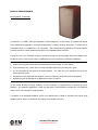
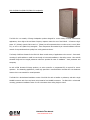
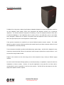
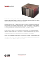
EMS Series
User Manual – v2.0
EMS-81/EMS-81i
EMS-121/EMS-121w/EMS-121i/EMS-121h
EMS-152/152w
EMS-215/EMS-215i
EM Acoustics Loudspeakers
Building 74, Dunsfold Park
Cranleigh, Surrey
GU6 8TB, UK
Phone +44 (0) 1483 266520
Fax +44 (0) 1483 275619
www.emacoustics.co.uk
_________________________________________________________________________________________
Copyright EM Acoustics 2006
1
EMS Series User Manual
www.emacoustics.co.uk
CONTENTS
Introduction
Thank you ...……………………………………………………………………………………………………………………………. 3
Unpacking ……………………………………………………………………………………………………………………………….. 3
Declaration of Conformity …………………….…………………………………………………………………………………… 3
Product Range Overview
EMS-81 passive two-way fullrange enclosure ……………………………………………………………………………… 4
EMS-121 passive two-way fullrange enclosure ……………………………………………………………………………. 5
EMS-152 passive two-way fullrange enclosure ……………………………………………………………………………. 6
EMS-215 subwoofer …………………………………………………………………………………………………………………. 7
System Set-up
Safety Considerations………………………………………………………………………………………………………………… 8
Cabling & Amplifier selection ……………………………………………………………………………………………………… 9
Mounting & Rigging Options
Rigging Hardware & Accessories ………………………………………………………………………………………………… 10
Permanent Installations …………………………………………………………………………………………………………….. 10
Vertical Flying Cradle Use ……………………………….…………………………………………………………………………. 11
Horizontal Flying Cradle Use …….…………………………………………………………………………………................ 12
Dual Enclosure Flybar Use ………………………………………………………………………………………………. …………13
EMS-152 Rigging Options …………………………………………………………………………………………………………… 14
Ommimount/Powerdrive Bracket Use …………………………………………………………………………………………… 15
DA-1 Amplifier Installation ………………………………………………………………………………………………………………………16
Maintenance
EMS-81 Drive Unit Service ………………………………………………………………………………………………………….17
EMS-121 Drive Unit Service ………………………………………………………………………………………………………. 18
EMS-152 Drive Unit Service ………………………………………………………………………………………………………. 19
EMS-215 Drive Unit Service ………………………………………………………………………………………………………. 20
Warranty ……………………………………………………………………………………………………………………………………………. 21
Appendix A – Technical Specifications …………………………………………………………………………………………………… 22
2
EMS Series User Manual
www.emacoustics.co.uk
INTRODUCTION
Thank you
Thank you for purchasing a product from the acclaimed EMS Series from EM Acoustics. The EMS Series products
have been carefully designed and rigorously tested to ensure years of flawless operation and unprecedented sonic
quality. Flexibility is the key factor with EMS products, and consequently they are at home within a wide variety of
applications from live and portable applications, through to cafes, bars, nightclubs, theatres and conference
centres.
Please ensure that you read this manual carefully before use, and that you keep it to hand should you need it for
further reference. Furthermore, should you have any difficulties please do not hesitate in contacting your EM
Acoustics dealer, or email [email protected] for further assistance.
Unpacking
Every EM Acoustics product is built to the highest standard and thoroughly tested before it leaves our factory.
After unpacking your loudspeaker, please inspect it carefully for any signs of transit damage. If such damage is
found, please notify the carrier at once to instigate a claim. It is suggested that you retain all packaging for future
re-shipment.
DECLARATION OF CONFORMITY
The products contained within this manual conform to the requirements of the EMC
Directive 89/336/EEC, amended by 92/31/EEC and to the requirements of the Low
Voltage Directive 73/23/EEC amended by 93/68/EEC.
Standards Applied:
EMC
Emission
EN55103-1:1996
Immunity
EN55103-2:1996
Electrical Safety
EN60065:1993
RECYCLING
This product and its packaging constitute the applicable product according to the WEEE directive.
Please ensure that at the end of the working life of this product, it is disposed of sensibly in
accordance with local and national recycling regulations. The packaging supplied with this product
is recyclable. Please retain all packaging, however if disposing of this packaging please ensure
that you comply with local recycling regulations. These products also all comply to the RoHS
Directive 2002/95/EC.
3
EMS Series User Manual
www.emacoustics.co.uk
PRODUCT RANGE OVERVIEW
EMS-81/EMS-81i Loudspeaker
The EMS-81 is a versatile, full-range loudspeaker product designed for a wide variety of compact and discreet
sound reinforcement applications. It features a high-power 8” (203mm) vented LF driver and a 1” (25mm) exit HF
compression driver on a rotatable 90° x 60° waveguide. These components are matched by an internal UniPhase
crossover network for unprecedented sonic quality from a completely passive enclosure.
Through the use of the multi-angle enclosure, polemount socket, M10 and M6 rigging points and rotatable horn,
the EMS-81 can be used in a wide variety of applications from floor monitoring to permanent installations.
To rotate the HF waveguide:
1. Remove the front grille as described in the Maintenance section on Page 10 of this manual.
2. Using a 4mm Allen key, remove the four socket-head bolts retaining the HF waveguide in place.
3. Lift the waveguide up and rotate to the desired position – the wider exit of the waveguide shows the 90degree dispersion plane.
4. Reinstate the socket-head bolts and retighten. Avoid over-tightening as this may crack the waveguide.
5. Reinstate the grille as described in the Maintenance section on Page 10.
As with all EM Acoustics full-range products, no active controller or programmed EQ is required for correct
operation. For demanding applications, a 50Hz high pass filter is recommended to increase drive unit headroom
however this is not essential for normal operation.
The EMS-81i is the dedicated installation version of the EMS-81 with no handle or polemount, and with a single
NL4MP connector and a four-way barrier strip instead of two NL4MP connectors.
4
EMS Series User Manual
www.emacoustics.co.uk
EMS-121/EMS-121w/EMS-121h/EMS-121i Loudspeaker
The EMS-121 is a versatile, full-range loudspeaker product designed for a wide variety of sound reinforcement
applications, where higher SPL and lower frequency response restrict the use of the EMS-81. It features a highpower 12” (305mm) vented LF driver and a 1” (25mm) exit HF compression driver on either a 60°H x 40°V (EMS121) or 90°H x 40°V (EMS-121w) waveguide. These components are matched by an internal UniPhase crossover
network for unprecedented sonic quality from a truly passive enclosure.
The family of different formats for the EMS-121 allows a wide variety of applications to be covered – from standmounting for public address or small live use through to horizontal installation in low-ceiling venues. M10 and M8
threaded fixings and an integral polemount socket are provided for ease of installation – both permanent and
temporary.
As with all EM Acoustics full-range products, no active controller or programmed EQ is required for correct
operation. For demanding applications, a 40Hz high pass filter is recommended to increase drive unit headroom
however this is not essential for normal operation.
The EMS-121i is the dedicated installation version of the EMS-121 with no handles or polemount, and with a single
NL4MPR connector and a four-way barrier strip instead of two NL4MPR connectors. The EMS-121h is a horizontal
mounting, permanent installation version for use in situations where ceiling height is critical.
5
EMS Series User Manual
www.emacoustics.co.uk
EMS-152/EMS-152w Loudspeaker
DA-1 Ready
The EMS-152 is a high power, medium-Q performance loudspeaker designed for a variety of applications within the
live and installation audio markets, where sonic performance and dispersion accuracy are of paramount
importance. The enclosure features a high-power 15” (381mm), 4” voice coil neodymium vented LF driver and a
4” aluminium diaphragm, 2” exit compression driver on either a 60°H x 40°V (EMS-152) or 90°H x 40°V (EMS152w) waveguide. Added to this is a specific cone profile to allow the dispersion of the 15” drive unit to match
that of the high frequency drive unit throughout the crossover region.
These precision components are matched by an internal UniPhase2 passive crossover network.
This radical
approach to passive crossover technology achieves phenomenal frequency and phase responses without the need
for bi-amplification or external processing.
The two formats are intended to provide user-flexibility during system design – the EMS-152 is designed for array
construction whereas the EMS-152w can be used where wider coverage is required from a single enclosure – such
as centre fills or large format front fills.
Integral to the enclosure are four M10 flying points to allow suspension using a variety of different rigging
methods.
As with all other EM Acoustics fullrange products, no external processing or equalisation is required to allow the
loudspeaker to function correctly.
However, for high SPL applications a high pass filter set above 40Hz is
recommended to remove unnecessary LF drive unit cone excursion. The EMS-152 can also accept the new DA-1
digital power amplifier module if required.
6
EMS Series User Manual
www.emacoustics.co.uk
EMS-215/EMS-215i Subwoofer
DA-1 Ready
The EMS-215 is a compact, powerful subwoofer system designed to extend the low frequency performance of
EMS-81 and EMS-121 based systems. Through the use of a quasi-bandpass design, the enclosure size is kept to a
minimum to allow ease of use in installations where space is a premium.
It features a pair of high power 15” (381mm) LF drive units, each in their own vented chamber. Both drive units
then fire through a single exit, located behind the foam grille. For ease of transportation in portable applications,
the EMS-215 is fitted with four heavy duty castors and recessed handles. Three polemounts are also fitted to allow
the mounting of EMS-81 or EMS-121 enclosures above the subwoofer, in two different orientations.
An active crossover is required to set a low pass filter for correct operation, set at any point below 150Hz. A
24dB/Octave Linkwitz-Riley filter slope is recommended. For demanding applications, a 30Hz high pass filter is
recommended to increase drive unit headroom however this is not essential for normal operation.
The EMS-215i is the dedicated installation version of the EMS-215 with no handles, wheels or polemounts, and
with a single NL4MPR connector and a four-way barrier strip instead of two NL4MPR connectors. The EMS-215 can
also accept the new DA-1 digital power amplifier module if required.
7
EMS Series User Manual
www.emacoustics.co.uk
SYSTEM SET-UP
Safety Considerations
Loudspeaker systems are potentially dangerous objects if used incorrectly.
Please ensure that you read this
section fully, and contact EM Acoustics or your local dealer should you be in any doubt over correct operation
procedures.
Professional loudspeaker systems are capable of producing damage-inducing sound pressure levels, and hence
care should be taken when setting your system up, particularly when it comes to loudspeaker placement within a
venue. Damage to the ear can result from levels above 90dB under prolonged exposure.
Stand Mounting
The EMS-81 and EMS-121 include 35mm polemount sockets for stand mounting. When mounting in this way,
please consider the following:
•
Ensure your stand height is locked off and the tripod legs are positioned so as to be stable.
•
Check the weight loading of your stands before attempting to mount the loudspeaker.
•
Do not stack a second loudspeaker on top of the stand-mounted one.
•
Ensure cables are run so as to leave enough slack to enable neat wiring, and thus reduce the risk of the
speaker being pulled over. Loose cables should be covered or taped down wherever possible to reduce trip
hazards.
•
If stands are being used outdoors, it may be necessary to add ballast to the base of the stand to prevent it
toppling over.
•
When using poles on top of subwoofer systems, please observe similar precautions.
Ground Stacking
•
Ensure that the floor or stage surface can withstand the weight of the system.
•
Wherever possible, avoid high stacks and use ratchet straps to secure loudspeakers together. Please also
remember that vibrations from subwoofer systems can shake other loudspeakers out of place, which may
present a toppling hazard. The use of ratchet straps and non-slip material is recommended to prevent this.
Rigging and Suspension
There are a variety of different methods for suspending your EMS-81 and EMS-121 enclosures – please see the
detailed section on Page 9 for further information.
WARNING: The overhead suspension of loudspeakers is a very serious issue with potentially lethal
consequences should anything go wrong.
Rigging should only be carried out by experienced
8
EMS Series User Manual
www.emacoustics.co.uk
personnel following safe working practice. Should you be in any doubt whatsoever, please contact
your local dealer who will be able to refer you to a suitable rigging company.
Cabling and Amplifier Selection
The EMS Series products are designed to be used with professional power amplifiers providing the following power
outputs:
EMS-81
500W/channel into eight ohms
EMS-121
700W/channel into eight ohms
EMS-152
1200W/channel into eight ohms
EMS-215
1600W/channel into four ohms
A small power amplifier working too hard is more likely to damage a loudspeaker than a large power amplifier
working within its operating range!
It is good practice to use an amplifier equal to the program power rating of the loudspeaker – so as to retain
sufficient headroom and good dynamic range. Care should be taken during operation to avoid amplifier clipping –
as this can cause serious damage to your loudspeakers. If in doubt, please contact your dealer who will be happy
to assist you in correct amplifier choice and setup.
Cabling
All EMS Series products are supplied with Neutrik SpeakonTM NL4 connectors, wired pin 1+/1-. It is recommended
that the resistance of your cable is less than one tenth of the nominal system impedance. Given below are the
recommended maximum cable lengths for different cross-sections and impedances.
Conductor Cross Sectional Area
Maximum Recommended Cable Length
4 ohms
8 ohms
16 ohms
2
11m
22m
44m
2
17m
34m
68m
2
2.0mm
22m
44m
88m
2.5mm2
29m
58m
116m
2
44m
88m
176m
2
66m
132m
264m
1.0mm
1.5mm
4.0mm
6.0mm
9
EMS Series User Manual
www.emacoustics.co.uk
MOUNTING & RIGGING OPTIONS
Rigging Hardware & Accessories
The EMS-81 and EMS-121 loudspeakers have a range of integral rigging hardware and optional accessories to
enable usage in a wide variety of ways.
The EMS-81 contains ten M10 threaded fixing points around the enclosure, to enable suspension using forged
shoulder eyebolts (minimum thread length 20mm) or the optional FC-81v vertical or FC-81h horizontal flying
cradles. These fixings allow suspension in any orientation, with the rear point being used for pull-back to obtain
the desired rigging angle. The EMS-81 also includes four M6 threaded fixings on the rear of the enclosure for use
with OmnimountTM Series 30 or PowerdriveTM Series 75 mounting products.
The EMS-121 contains twelve M10 threaded fixings around the enclosure, to enable similar suspension techniques
as for the EMS-81. The optional FC-121v vertical and FC-121h horizontal flying cradles can also be used for
enclosure suspension.
Also included are four M8 threaded fixings on the rear of the enclosure for use with
OmnimountTM Series 60 or PowerdriveTM Series 100 mounting products.
For array assembly, the DFB-81 and DFB-121 dual flybars are available from your EM Acoustics representative.
These steel plates allow two enclosures to be bolted together, with an angle variable from 0 degrees to 40 degrees
splay between the two enclosures.
The EMS-152 has a pair of M10 threaded fixings on the top and bottom of the enclosure for a variety of different
suspension methods, primarily aimed at flexible touring solutions. See the section on page 13 for more details.
With any suspension method, a second anchor point should be used as a safety.
Under no circumstances should the mounting points of one enclosure be used to suspend another
enclosure below it.
EM Acoustics are in no way responsible for the failure of incorrectly rigged
systems. This information relates specifically to the rigging techniques for the EMS-81 and EMS-121
enclosures only. If you are in any doubt about safe practices for rigging loudspeakers, please contact
your local EM Acoustics dealer who will be able to advise you.
Permanent Installations
Any installation (permanent or temporary) must be securely attached to the structure of the building using chain,
steel wire or web straps that are certified and load rated for the loudspeaker system. Consideration must be taken
10
EMS Series User Manual
www.emacoustics.co.uk
when determining the loading on the structure to include loudspeakers and rigging hardware, and the appropriate
safety factor can then be decided upon.
If you are in any doubt whatsoever, please contact your EM
Acoustics dealer who will be able to refer you to an experienced rigging company. A reputable rigging organisation
should also be able to advise on legislation regarding safety factors for suspended systems of this type.
Attachment of the FC-81v or FC-121v Vertical Flying Cradles
The EMS-121 enclosure is shown in the drawings, however the technique is the same for both the EMS-81 and
EMS-121 enclosures. Lie the enclosure down on its front, and remove the two M10 countersunk bolts on each side
of the enclosure (marked “A” in Fig 1). Fit the cradle over the rear of the enclosure as shown in Fig 1 below, and
reinstate the M10 bolts into the holes.
The M12 hole at the top of the cradle can be used for either direct fixing in installations, or a hook-clamp or quickrelease scaffolding clamp to attach the enclosure to the suspension point. Fit the desired attachment device and
stand the enclosure upright, returning the cradle to the vertical orientation (Fig 2). Attach the enclosure to the
suspension point, and tighten the clamp. A secondary safety should always be used – this can be done in two
ways. Method one involves attaching an M10 forged shoulder eyebolt to the rear pull-back point of the enclosure
and then attaching a steel cable or chain between this point and your suspension point. Method two involves
wrapping a safety cable around the top part of the cradle (marked “B” in drawings) and around the suspension
bar. Once the enclosure is suspended safely, adjust to the desired angle by loosening the plastic knurled knobs on
each side (marked “C”), positioning where required and retightening.
Additional strength can be gained by
tightening the M5 locking bolt on each side (marked “D”) using an 8mm spanner. Rotate the enclosure to the
desired position and tighten the bolt securing the attachment device.
11
EMS Series User Manual
www.emacoustics.co.uk
Attachment of the FC-81h or FC-121h Horizontal Flying Cradles
The EMS-121 enclosure is shown in the drawing, however the technique is the same for both the EMS-81 and EMS121 enclosures.
Remove the M10 countersunk bolts on the top & bottom of the enclosure (marked “A” in Fig 1), position the end
sections of the flying cradle and reinstate the bolts. Bolt the chosen attachment method to the top of the cradle,
and secure the enclosure onto the suspension point or bar. As with the vertical cradles, a secondary safety point
should be used.
Once the enclosure is suspended, release the plastic knurled knobs (marked “B” in Fig 1) on each side of the cradle
and position the enclosure as desired. Once the enclosure is in place, lock off the attachment device to prevent
the enclosure rotating, and use the M5 locking bolts (marked “C” in Fig 1) to secure completely.
12
EMS Series User Manual
www.emacoustics.co.uk
Attachment of the DFB-81 or DFB-121 flying bar
The EMS-121 enclosure is shown in the drawing, however the technique is the same for both the EMS-81 and EMS121 enclosures.
Position the two enclosures upright on a stable surface. Remove the M10 countersunk screws on the top of the
enclosure (marked “A” in Fig 1) on both enclosures. Position the DFB-121 above the enclosure, and fit M10 forged
shoulder eyebolts into the outer pair of mounting holes (marked “B” in Fig 2) and standard M10 hex-head set
screws into the inner pair of holes (marked “C” in Fig 2). Do not tighten these bolts until your array position is set
to the splay angle you require, indicated by the label on top of the plate. Once you have the desired angle, tighten
all bolts.
Carefully turn the cluster upside down, and repeat the above process. There is no need to fit eyebolts on the
underside of the enclosure.
Once your cluster is assembled, it can be suspended using steel cables or chains from the eyebolts. To set a
down-tilt angle, attach a shackle to the rear M12 hole on the lower DFB-121 (marked “D” in Fig 2), and utilise this
point to set the desired down-tilt. Assuming that this point is secured onto a solid structure, this down-tilt angle
point can be used as a secondary safety for the cluster. Alternatively, remove one of the countersunk M10 bolts
on the rear of the enclosures and fit another M10 eyebolt as a safety point.
13
EMS Series User Manual
www.emacoustics.co.uk
EMS-152 Rigging Options
There are several different options for suspending an EMS-152 enclosure, detailed below.
Suspension using forged shoulder eyebolts
The EMS-152 can be simply suspended for more permanent applications using a pair of M10 forged shoulder
eyebolts with a 20mm thread length. Simply screw the eyebolts into the two M10 mounting points on the top (or
bottom if flying upside down) of the enclosure. These can then be attached to steel cables or chains to suspend
the enclosure. For setting down or up-tilt angle, insert an M10 eyebolt into one of the rear M10 points and attach
an additional cable or chain – alternatively vary the front or rear chain length on the main points to adjust the
suspension angle.
Attachment of the VFA-152 Variable angle suspension bracket
The VFA-152 is intended to provide an in-place solution for varying the down or up-tilt angle of the enclosure.
Using the two M10 socket head bolts (supplied with the VFA-152), bolt the enclosure to the VFA-152 using points
marked “A”. The quick-lock clamp on top of the VFA-152 (marked “B” in Fig 1) can be used either to attach
directly to a suspension point, or else where the desired height of the enclosure is lower than the suspension point
(for example in proscenium arch theatre use), suspend a small length of scaffolding bar using traditional wires or
chains and then attach the VFA-152 to this. A secondary safety cable or chain should be attached to the eyebolt
on the VFA-152 (marked “C” in Fig 1). By adjusting the knob at the rear of the VFA-152 using a 19mm socket
(point “D” on Fig 1), the hanging point can be moved. This adjustment moves the suspension fulcrum relative to
the enclosure’s centre of gravity, and hence will adjust the suspension angle.
14
EMS Series User Manual
www.emacoustics.co.uk
Attachment of the DFB-152 flying bar
The attachment method is the same as for the DFB-81 or 121 – the only difference being the attachment points
are the exposed M10 threaded fixings front and back on the enclosure’s centreline.
Attachment of the FC-152v flying cradle
Follow the procedure outlined on Page 11 above, using M10 bolts into the exposed M10 flying points front and
back on the enclosure’s centreline.
Attachment of OmnimountTM or PowerdriveTM Installation Brackets
It is strongly suggested that you position your loudspeakers, then mark & drill the holes in the mounting walls
before you attach the bracket to the loudspeaker, as it is much easier to check positioning and fit of the holes
without the weight of the loudspeaker.
The EMS-81 is designed to work with OmniMountTM Series 30 or PowerDriveTM Series 75 products.
Lie the enclosure on its front and remove the four M6 countersunk points on the rear of the enclosure. Position
the loudspeaker-side of the bracket as required, reinstate the bolts and retighten. The bracket and EMS-81 can
now be mounted using the holes you have pre-drilled.
The EMS-81 is designed to work with OmniMountTM Series 60 or PowerDriveTM Series 100 products.
Lie the enclosure on its front and remove the four M6 countersunk points on the rear of the enclosure. Position
the loudspeaker-side of the bracket as required, reinstate the bolts and retighten. The bracket and EMS-121 can
now be mounted using the holes you have pre-drilled. This method is the same for all variants of the EMS-121
(EMS-121, EMS-121w, EMS-121h).
Safety Considerations
When utilising any suspension method, a secondary safety must be used. For any suspension method, remove
one of the rear M10 countersunk machine screws and replace with a forged should M10 eyebolt. A safety steel
can then be attached to this and connected to your safety point. If you are in any doubt whatsoever about
how to safely suspend your loudspeakers, do not hesitate to contact your EM Acoustics
representative who will be able to refer you to a qualified rigging company for advice.
15
EMS Series User Manual
www.emacoustics.co.uk
Installation of the DA-1 Power Amplifier Module
The EMS-152 fullrange loudspeaker and EMS-215 subwoofer can accept the EM Acoustics DA-1 digital power
amplifier module. One DA-1 is used to drive one loudspeaker, in the following configurations:
EMS-152 – bridge-mono mode, with the two amplifier channels driving the internal passive circuitry.
EMS-215 - two channel mode, with each drive unit driven by one channel.
To install the DA-1, lie the enclosure on its front. Using a 4mm Allen Key, carefully undo the six M5 socket head
bolts holding the connector panel door in place on the rear of the enclosure. Remove the connector panel door
and disconnect the four-pin connector on the cable. Put the connector panel aside for future reinstatement.
Connect the four-pin connector into the chassis socket on the bottom edge of the DA-1. Carefully place the DA-1
into the amplifier module housing within the enclosure, reinstate and retighten the M5 socket head bolts.
The DA-1 must be set to the correct program before use, otherwise severe damage can occur to your loudspeaker.
Please consult your DA-1 user manual for information on recalling programs, and a program listing.
16
EMS Series User Manual
www.emacoustics.co.uk
MAINTENANCE
Your EM Acoustics loudspeakers have been rigorously tested before they leave our factory, to ensure that they give
you a lifetime of flawless operation. Should any of your drive units fail and need replacing, please follow the
guidelines below.
EMS-81: Low Frequency Drive Unit
1. Carefully insert a flat bladed screwdriver between the grille and the top of the enclosure, and gently lever the
grille upwards. This will ease the grille out of its locating slots along the side of the enclosure, revealing the
drive units. Ensure to approach the grille at the top of the enclosure (handle end) as this will prevent the risk
of the screwdriver damaging the LF drive unit.
2. Using a 4mm Allen key, remove the eight M5 socket-head bolts holding the drive unit in place, and keep them
safe – ensuring you have collected both the shake-proof and flat washers for each bolt. Gently lift the drive
unit out of its locating hole – please take care as it is heavy! Carefully disconnect the cables from the drive
unit.
3. To reinstate the driver, simply reverse the above procedure. Please observe the correct polarity – red cable to
positive terminal, black cable to negative.
4. Reinstate the grille by easing into one side slot, then gently applying a curve to the grille to ease it into the
other side.
EMS-81: High Frequency Drive Unit
1. Follow the procedure above to remove the LF drive unit.
2. Using a 4mm Allen key, remove the four M5 socket-head bolts holding the HF waveguide in place, and as
above put them to one side and ensure you have all the washers. Remove the white BAF wadding from inside
the enclosure. Reaching inside through the LF drive unit hole, lift the compression driver upwards from behind
to expose the two M5 hex head bolts that attach the drive unit to the waveguide. Using an 8mm spanner,
undo these bolts to lift the waveguide clear. The HF drive unit can then be removed through the LF drive unit
hole – once the cables have been disconnected.
3. To reinstate the drive unit, reconnect the cables (white cable to positive terminal, yellow cable to negative)
and reposition below the HF waveguide hole. Using an 8mm spanner, retighten the M5 hex head bolts and sit
the waveguide back in place before reinstating the four socket-head bolts. Avoid over-tightening these bolts
as this may crack the waveguide. Note also the dispersion orientation of the waveguide – the small
marks on two sides of the waveguide mounting flange indicate the 90-degree dispersion plane.
4. Reinstate the BAF wadding, and the LF driver as described in point 3 above (LF driver removal).
5. Reinstate the grille by easing into one side slot, then gently applying a curve to the grille to ease it into the
other side.
17
EMS Series User Manual
www.emacoustics.co.uk
EMS-121: Low Frequency Drive Unit
1. Carefully insert a flat bladed screwdriver between the grille and the top of the enclosure, and gently lever the
grille upwards. This will ease the grille out of its locating slots along the side of the enclosure, revealing the
drive units. Ensure to approach the grille at the top of the enclosure as this will prevent the risk of the
screwdriver damaging the LF drive unit.
2.
Using a 5mm Allen key, remove the eight M6 socket-head bolts holding the drive unit in place, and keep them
safe – ensuring you have collected both the shake-proof and flat washers for each bolt. Gently lift the drive
unit out of its locating hole – please take care as it is heavy! Carefully disconnect the cables from the drive
unit.
3. To reinstate the driver, simply reverse the above procedure. Please observe the correct polarity – red cable to
positive terminal, black cable to negative.
4. Reinstate the grille by easing into one side slot, then gently applying a curve to the grille to ease it into the
other side.
EMS-121: High Frequency Drive Unit
1. Carefully insert a flat bladed screwdriver between the grille and the top of the enclosure, and gently lever the
grille upwards. This will ease the grille out of its locating slots along the side of the enclosure, revealing the
drive units. Ensure to approach the grille at the top of the enclosure as this will prevent the risk of the
screwdriver damaging the LF drive unit.
2. Using a 5mm Allen key, remove the four M6 socket-head bolts holding the HF waveguide in place, and as
above put them to one side and ensure you have all the washers. Lift the waveguide out of the mounting hole
and disconnect the cables.
3. To remove the drive unit, undo the three M5 hex head bolts that attach the drive unit to the waveguide using
an 8mm spanner.
4. To reinstate the drive unit, reattach the M5 hex head bolts and retighten. Reconnect the cables (white cable
to positive terminal, yellow cable to negative) and reposition the waveguide in the mounting hole before
reinstating the four M6 socket-head bolts.
5. Reinstate the grille by easing into one side slot, then gently applying a curve to the grille to ease it into the
other side.
18
EMS Series User Manual
www.emacoustics.co.uk
EMS-152: Low Frequency Drive Unit
1. Carefully lift back the foam on the top & bottom edges of the grille.
Remove the five
PoziDrive screws (3 top, 2 bottom using a PZ2 screwdriver) and insert a flat-blade
screwdriver under the grille. This can then be used to ease the grille out of its locating slots.
2.
Using a 5mm Allen Key, undo the six bolts securing the drive unit in place. The drive unit can then be
lifted out of place by using your finger or a flat blade screwdriver into the recesses in the baffle. Carefully
disconnect the cables from the drive unit.
3.
To reinstate the drive unit, simply reverse the above procedure. Please observe correct polarity – red
cable to positive terminal, black to negative. When tightening the six M6 bolts holding the drive unit in
place, it is a good idea to run a sine wave signal through the enclosure to ensure that the drive unit is
evenly tensioned around its circumference. Uneven tension will be apparent by the sound of the voice coil
rubbing.
4.
Reinstate the grille by easing into one slot, then gently applying a curve to the grille and easing it into the
other slot. Reinstate the screws and push the foam back into place.
EMS-152: High Frequency Drive Unit
1. Follow the procedure above to remove the grille.
2.
Using a 5mm Allen Key, undo the ten bolts securing the waveguide in place. The assembly can then be
lifted out of place. Carefully disconnect the cables from the drive unit as soon as you can reach them to
avoid placing unnecessary strain on the crossover network.
3.
To remove the drive unit from the waveguide, use a 7/16” spanner to undo the four locking nuts.
4.
To reinstate the drive unit, simply reverse the above procedure. Ensure when reconnecting the cables
that you not only observe correct polarity (white to positive terminal, yellow to negative) but also that the
cable threads through the HF support brace, otherwise it will prevent the drive unit sitting correctly in
place. Reposition the waveguide correctly and then reinstate the ten bolts, ensuring you have all three
washers for each bolt (shakeproof, flat steel and flat nylon).
5.
Reinstate the grille by easing into one slot, then gently applying a curve to the grille and easing it into the
other slot. Reinstate the screws and push the foam back into place.
EMS-152: HF Diaphragm replacement
1.
Lie the enclosure on its front.
2.
Using a 3mm Allen key, undo the four countersunk M5 bolts holding the rear HF door in place.
3.
Disconnect the cables, and using a 3mm Allen key, undo the bolts securing the back cap of the driver.
4.
Use a PZ2 screwdriver to remove the screws holding the diaphragm in place.
5.
Sit a new diaphragm in place, and reinstate the screws. Reconnect the cables and run a sine wave signal
through the enclosure to ensure that the diaphragm is properly centred before applying final tension to the
diaphragm screws.
6.
Reposition the rear door and retighten the M5 countersunk bolts.
19
EMS Series User Manual
www.emacoustics.co.uk
EMS-215: Low Frequency Drive Units
NOTE: ONLY ATTEMPT TO REMOVE DRIVE UNITS WITH THE EMS-215 IN AN UPRIGHT POSITION!
1. Carefully lift the foam along the long edges of the grille to expose the three locating screws on each side.
Using a No.2 Pozidrive screwdriver, undo these screws and keep them to one side.
2. Insert a flat bladed screwdriver between the enclosure and the long edge of the grille, and gently lever the
grille upwards. This will ease it out of its locating slots down the shorter sides.
3. Using a 10mm spanner or socket driver, undo the six M6 hex head bolts holding the lower drive unit in place.
Remove these bolts and ensure that you have both shake-proof and flat washers.
4. Lift the drive unit out of the mounting hole, ensuring that you do not hit the drive unit above when removing
it. Take care as the drive units are very heavy. Disconnect the cables before lifting the drive unit clear.
5. To remove the other drive unit, turn the enclosure the other way up and repeat the procedure.
6. To reinstate the drive unit, simply reverse the procedure above, ensuring that you have the correct polarity on
the drive unit cables (red cable to positive terminal, black cable to negative).
7. Reinstate the grille by easing into one side slot, then gently applying a curve to the grille to ease it into the
other side.
8. Reinstate the six Pozidrive screws to secure the grille in place.
20
EMS Series User Manual
www.emacoustics.co.uk
WARRANTY
Limited Warranty
This EM Acoustics loudspeaker product is warranted to the original end-user purchaser and all subsequent owners
for a period of three years from the original date of purchase.
Warranty Coverage
This warranty covers defects in materials and workmanship. It does not include:
•
Damage or failure caused by accident, misuse, neglect, abuse or modification by any person other than an
authorised EM Acoustics representative.
•
Damage or failure caused by operating the loudspeaker product contrary to the instructions contained within
this manual.
•
Damage caused during shipment.
•
Claims based on any misrepresentation by the seller.
•
Products which contain anything other than the original components (or EM Acoustics factory supplied spare
parts).
•
Products on which the serial number has been removed, altered or defaced.
Returning your EM Acoustics loudspeaker
Should your EM Acoustics loudspeaker develop a fault, please return it (freight prepaid) in its original packaging,
along with proof of purchase to your local dealer or to:
EM Acoustics (Returns Department), Building 74, Dunsfold Park, Cranleigh, Surrey, GU6 8TB, UK
including a description of the suspected fault. Serial numbers must be quoted in all correspondence relating to the
claim. EM Acoustics or its representatives are in no way liable for any loss or damage in transit, and hence it is
recommended that the sender insure the shipment. EM Acoustics will pay for return freight should the repair be
covered under warranty.
EM Acoustics’ liability is to the replacement or repair (at our discretion) of any defective components, and as such
are not liable for any incidental and consequential damages including (without limitation) injury to persons,
damage to property or loss of use.
This warranty is exclusive and no other warranty is expressed or implied. This warranty is also in
addition to – and in no way detracts from – your statutory rights as a consumer.
21
EMS Series User Manual
www.emacoustics.co.uk
APPENDIX A – TECHNICAL SPECIFICATIONS
EM Acoustics operates a continuous process of research and development, and as such reserves the right to alter specifications without notice.
EMS-81
Enclosure Type:
2-way, reflex loaded
Dimensions (HxWxD, mm/ins):
461/18.1 x 308/12.1 x 268/10.6
Net Weight:
13kg
Frequency Response (+/- 3dB):
80Hz – 20KHz
Sensitivity:
96dB, 1W/1m
Dispersion:
90°H x 60°V (rotatable)
Drive Units:
8” (203mm) LF cone drive unit
1” (25mm) exit HF compression drive unit
Power Handling:
250W RMS, 500W Program
Maximum SPL:
120dB continuous, 126dB peak
Nominal Impedance:
8 ohms
Crossover:
UniPhase internal passive
Connectors:
2 x Neutrik SpeakonTM NL4MP
Enclosure:
15mm (5/8”) Finnish Birch plywood
Rigging/Suspension:
10 x M10 threaded fittings, 4 x M6 threaded fittings
35mm polemount socket
Grille:
Acoustically transparent black foam on expanded steel mesh
Options:
Colours
Connectors
EMS-81i (install version)
Spares & Accessories:
FC-81v vertical flying cradle
FC-81h horizontal flying cradle
DFB-81 dual flying bar
DU-802 replacement LF drive unit
CDU-1001 replacement HF compression drive unit
RK-802 re-cone kit for DU-802
RD-1001 replacement diaphragm for CDU-1001
RFG-81 replacement foam/grille
UN-1/81 UniPhase crossover network – EMS-81 version
22
EMS Series User Manual
www.emacoustics.co.uk
EMS-121
Enclosure Type:
2-way, reflex loaded
Dimensions (HxWxD, mm/ins):
595/23.4 x 402/15.8 x 341/13.4
Net Weight:
22kg
Frequency Response (+/- 3dB):
65Hz – 20KHz
Sensitivity:
98dB, 1W/1m
Dispersion:
60°H x 40°V (EMS-121)
90°H x 40°V (EMS-121w)
Drive Units:
12” (305mm) LF cone drive unit
1” (25mm) exit HF compression drive unit
Power Handling:
350W RMS, 700W Program
Maximum SPL:
126dB continuous, 132dB peak
Nominal Impedance:
8 ohms
Crossover:
UniPhase internal passive
Connectors:
2 x Neutrik SpeakonTM NL4MPR
Enclosure:
15mm (5/8”) Finnish Birch plywood
Rigging/Suspension:
12 x M10 threaded fittings, 4 x M8 threaded fittings
35mm polemount socket
Grille:
Acoustically transparent black foam on expanded steel mesh
Options:
Colours
Connectors
EMS-121i (install version)
EMS-121h (horizontal install version)
Spares & Accessories:
FC-121v vertical flying cradle
FC-121h horizontal flying cradle
DFB-121 dual flying bar
DU-1202 replacement LF drive unit
CDU-1001 replacement HF compression drive unit
RK-1202 re-cone kit for DU-1202
RD-1001 replacement diaphragm for CDU-1001
RFG-121 replacement foam/grille
UN-1/121 UniPhase crossover network – EMS-121 version
23
EMS Series User Manual
www.emacoustics.co.uk
EMS-152
Enclosure Type:
2-way, medium-Q reflex loaded
Dimensions (HxWxD, mm/ins):
695/27.4 x 488/19.2 x 485/19.1
Net Weight:
42kg
Frequency Response (+/- 3dB):
65Hz – 18KHz
Sensitivity:
98dB, 1W/1m
Dispersion:
60°H x 40°V (EMS-152)
90°H x 40°V (EMS-152w)
Drive Units:
15” (381mm) LF cone drive unit
2” (50mm) exit HF compression drive unit
Power Handling:
600W RMS, 1200W Program
Maximum SPL:
132dB continuous, 138dB peak
Nominal Impedance:
8 ohms
Crossover:
UniPhase2 internal passive
Connectors:
2 x Neutrik SpeakonTM NL4MPR
Enclosure:
15mm (5/8”) Finnish Birch plywood
Rigging/Suspension:
6 x M10 threaded fittings
Grille:
Acoustically transparent black foam on expanded steel mesh
Options:
Colours
Connectors
EMS-152w
Spares & Accessories:
FC-152v vertical flying cradle
DFB-152 dual flying bar
VFA-152 Variable Angle flying bracket
DU-1503 replacement LF drive unit
CDU-2001 replacement HF compression drive unit
RK-1503 re-cone kit for DU-1503
RD-2001 replacement diaphragm for CDU-2001
RFG-152 replacement foam/grille
UN-2/152 UniPhase crossover network
24
EMS Series User Manual
www.emacoustics.co.uk
EMS-215
Enclosure Type:
Dual driver quasi-bandpass
Dimensions (HxWxD, mm/ins):
823/32.4 x 516/20.3 x 700/27.6 (excl. wheels)
Net Weight:
65kg
Frequency Response (+/- 3dB):
45Hz – 150Hz
Sensitivity:
100dB, 1W/1m
Drive Units:
2 x 15” (381mm) LF cone drive unit
Power Handling:
800W RMS, 1600W Program
Maximum SPL:
131dB continuous, 137dB peak
Nominal Impedance:
4 ohms
Crossover:
Active, recommended below 150Hz
Connectors:
2 x Neutrik SpeakonTM NL4MPR
Enclosure:
18mm (3/4”) Finnish Birch plywood
Rigging/Suspension:
3 x 35mm polemount sockets
Grille:
Acoustically transparent black foam on expanded steel mesh
Options:
Colours
Connectors
EMS-215i (install version)
Spares & Accessories:
DU-1501 replacement LF drive unit
RK-1501 re-cone kit for DU-1501
RFG-215 replacement foam/grille
25
EMS Series User Manual
www.emacoustics.co.uk