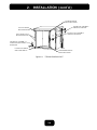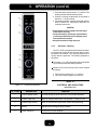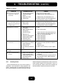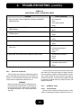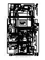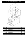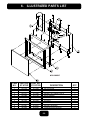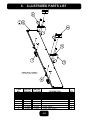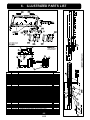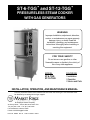
1
ST-6-TGG™ and ST-12-TGG™
PRESSURELESS STEAM COOKER
WITH GAS GENERATORS
WARNING
Improper Installation, adjustment, alteration,
service, or maintenance can cause property
damage, injury, or death. Read the
installation, operating, and maintenance
instructions thoroughly before installing or
servicing this equipment.
FOR YOUR SAFETY
Do not store or use gasoline or other
flammable vapors or liquids in the vicinity of
this or any other appliance.
MODEL
ST-6-TGG
ST-12-TGG
COVERING
• Installation
• Operation
• Service and Parts
INSTALLATION, OPERATION, AND MAINTENANCE MANUAL
Post in a prominent location to be followed in the event the user smells gas. This information shall
be obtained by consulting the local gas supplier.
An Employee-Owned Company
35 Garvey Street • Everett, MA 02149-4422 USA
Tel: (617) 387-4100 • Fax: (617) 387-4456
Fax Outside MA: 1-800-227-2659
E-Mail: [email protected]
Form No. S-4846
Rev. A
11/98
Printed in U.S.A.
TABLE OF CONTENTS
PARAGRAPH
PAGE
PARAGRAPH
SECTION 1 INTRODUCTION
1.1
1.2
1.3
Description ............................................ 1-1
Basic Functioning ................................. 1-1
Service ................................................. 1-1
4.1
4.2
4.3
4.3.1
4.3.2
4.3.3
4.3.4
4.3.5
4.3.6
SECTION 2 INSTALLATION
2.1
2.2
2.3
2.4
2.5
2.6
2.6.1
2.6.2
2.6.3
2.6.4
2.7
Assembly ............................................. 2-1
Setting in Place .................................... 2-1
Gas Connection .................................... 2-1
Electric Service Connections ................ 2-2
Water Connections ................................ 2-2
Installation Check-Out .......................... 2-2
Warm-up ............................................... 2-2
Timed Steam Mode .............................. 2-2
Constant Steam Mode .......................... 2-2
Shut-Down Procedure ........................... 2-3
Reversing the Doors ............................. 2-3
4.3.7
4.3.8
4.3.9
4.4
4.4.1
4.4.2
SECTION 3 OPERATION
3.1
3.2
3.2.1
3.2.2
3.2.3
3.3
3.3.1
3.3.2
3.3.3
3.4
3.4.1
3.4.2
3.5
Form No. S-4846 Rev. A
11/98
General ................................................. 4-1
Troubleshooting Guide .......................... 4-1
Electrical Troubleshooting
Procedures ....................................... 4-1
Incoming Power .................................... 4-3
Electrical Inspection ............................. 4-4
60-Minute Timer .................................... 4-4
Door Interlock Switch ............................ 4-6
Indicator Lights ..................................... 4-6
Cooking Compartment Thermostatic Switch
4-6
Buzzer .................................................. 4-7
Cold Water Condenser Circuit ............... 4-7
Wiring ................................................... 4-7
Water Level Control Board .................... 4-7
Testing the Water Fill Relay .................. 4-8
Testing the Low Water Relay ................ 4-8
SECTION 5 MAINTENANCE
Operating Controls and Indicators ......... 3-1
Operating Procedures ........................... 3-1
Daily Firing Procedure ........................... 3-1
Cooking ................................................ 3-1
Daily Shut-Down Procedure .................. 3-1
Cleaning ................................................ 3-1
Daily Cleaning ....................................... 3-1
Prolonged Shutdown and Cleaning ........ 3-1
Generator Cleaning ............................... 3-2
Drainage ............................................... 3-3
Cooking Compartment Drainage ............ 3-3
Drip/Spill Trough Drainage ..................... 3-3
Test Kitchen Bulletin ............................. 3-4
MARKET FORGE INDUSTRIES, INC.
35 GARVEY STREET EVERETT, MA 02149
TEL: 617-387-4100 TELEX: 91-9494
FAX: 617-387-4456 OUTSIDE MA: 800-227-2659
PAGE
SECTION 4 TROUBLESHOOTING
5.1
5.2
5.2.1
5.3
5.3.1
5.3.2
5.3.3
5.3.4
5.3.5
General ................................................. 5-1
Preventive Maintenance ....................... 5-1
Cooking Compartment Cleaning ............ 5-1
Repair and Replacement ....................... 5-1
Door Latch Tension Adjustment ............ 5-1
Door Handle Tension Adjustment .......... 5-1
Door Gasket Replacement .................... 5-2
Exterior Panel Removal ........................ 5-2
Water Solenoid Valve Replacement ...... 5-2
SECTION 6 ILLUSTRATED PARTS LIST
6.1
6.2
6.3
iii
General ................................................. 6-1
Ordering Information ............................. 6-1
Index of Illustrated Parts List ................ 6-1
Illustrated Parts List ........... 6-2 through 6-14
LIST OF ILLUSTRATIONS
FIGURE
PAGE
SECTION 3 OPERATION
3-1
SECTION 6
ILLUSTRATED PARTS LIST
Controls and Indicators ......................... 3-2
See Page 6-1
SECTION 4 TROUBLESHOOTING
4-1
4-2
Wiring Diagram, Model ST-6 ................. 4-5
Schematic Diagram,
Model ST-6 ....................................... 4-9
LIST OF TABLES
TABLE
PAGE
TABLE
SECTION 3 OPERATION
3-1
SECTION 4 TROUBLESHOOTING
Controls and Indicators ......................... 3-2
4-1
4-2
iv
Form No. S-4846
Rev. A
11/98
PAGE
General Troubleshooting Guide ............. 4-1
Electrical Fault Isolation Guide ............. 4-4
1. INTRODUCTION
This service and parts manual contains general information, installation operation, principles of operation, troubleshooting, and maintenance information for the Market Forge ST-6 Pressureless
Steam Cookers. Also included is a parts list in which each replaceable part is identified and shown
in an accompanying exploded view.
1.1 DESCRIPTION
When steam flowing inside the compartment has
raised the interior temperature to 195°F, the contacts of
a thermostatic switch automatically close, completing
the circuit to the timer motor and starting the cooking
time period. At the end of the set interval, timer contacts
switch to shut off the cooking operation and sound a
signal buzzer. The buzzer is silenced by returning the
timer dial to the OFF position. In the constant steam mode,
operation will be continuous.
Steam emitted from the compartment along with liquid cooking drainage are directed through a drain screen
inside the compartment into a cooker drain line. Both
drain lines are connected to a common condenser box
located in rear. A cold water solenoid valve connected to
the condenser box is automatically actuated by a thermostatic switch to condense the steam to water prior to
discharging into an external drain.
The ST-6-TGG and ST-12-TGG is a pressureless
steam cooker consisting of two independently controlled
compartments enclosed in a single cabinet. Each cooking compartment is provided with steam by individual
gas generator rated at 50,000 Btu/hr. Each compartment
is equipped with a separate three-piece door with inner
gasket plate isolated from the exterior surface. Door
latches operate by action for positive sealing of inner
door. Steam and steam-condensing circuits are electrically controlled. Operating controls are displayed on a
single front-mounted panel and include separate power
switches and timers with indicator lights for selection of
constant steam or 60-minute-long duration cooking.
A separate steam source is not required for operation
of the pressureless cooker. The model ST-6 TGG is powered by twin gas steam generators totalling 100,000 Btu/
hr. rate. The cooker is equipped for connection to all
necessary utilities, gas, electricity, hot and cold water,
and an open drain.
1.3 SERVICE
Required service, both preventive and corrective, is
explained in Section 6. Should repairs be required, a network of authorized agencies is available to assist with
prompt service. A current Directory of Authorized Service Agencies may be obtained by contacting:
1.2 BASIC FUNCTIONING
The Model TGG may be operated with only one
compartment in use; or both may be used simultaneously. Each compartment is equipped with identical
controls, allowing selection of constant steam or
60-minute timer operation. The cooker becomes operational when the power switch is depressed to “ON” and
the timer is set to constant steam, or the timer is set at
the desired cooking time and the compartment door is
closed. The indicator light comes on, allowing steam to
flow into the compartment.
MARKET FORGE INDUSTRIES, INC.
35 GARVEY STREET EVERETT, MA 02149
TEL: 617-387-4100 TELEX: 91-9494
FAX: 617-387-4456 OUTSIDE MA: 800-227-2659
Form No. S-4846 Rev. A
11/98
Product Service Department
Market Forge
35 Garvey Street
Everett, Massachusetts 02149
Telephone (617) 387-4100
The model and serial numbers must be referenced
when corresponding with Market Forge. The data plate
containing the serial number pertaining to the equipment
is located toward the front on the top panel of the cooker.
1-1
2.
INSTALLATION
2.1 ASSEMBLY
The boiler and its individual shut-off valve must be
disconnected from the gas supply piping system during any pressure testing of that system at test pressure in excess of 1/2 psig (3.45 k/PA).
The wiring diagram adhesive label is located on the
inside of the front panel.
This product must be installed in a room with adequate
air supply.
Minimum clearances from both combustible and noncombustible surfaces are 2" (51 mm) from right and
left wall and 2" (152 mm) from rear wall. Suitable for
installation on combustible floors/counters.
This unit is serviceable from the front and right side.
Do not install in such a manner that a service person
cannot remove the side panels. The optimum clearance on the right side is 12" (302 mm), 24" (604 mm)
on the left.
Keep this manual for future reference.
The Model ST-6-TGG is shipped strapped and bolted
to a skid, with cabinet feet in a separate container. Steps
required for assembly are as follows:
1. Remove the straps and four bolts that fasten the
equipment frame to the skid.
2. Install feet in threaded mounting locations of the
cabinet frame.
3. Mount the two baffles on studs located on the rightinside of the cooking compartments.
4. Mount the four pan support racks in brackets inside control compartments.
5. Attach the drip trough on studs located on the face
of the unit.
2.2 SETTING IN PLACE
2.3 GAS CONNECTIONS
The location of installation must be under an exhaust
hood, which will remove gas combustion products, small
amounts of water vapor emitted when the cooker doors
are opened, and exhaust fumes from the air. Level the
unit in final location by turning the adjustable feet. Using
the cabinet top as a reference, obtain level adjustment
left-to-right and front-to-back.
a. The generator is factory-adjusted for a gas input of
50,000 Btu/hr. at the pressure indicated. Please read
the rating plate on top of the unit. If this plate is marked
for a different gas than that supplied, notify your dealer
immediately. Install an external gas supply shut-off
valve in a visible and accessible location. If the unit is
placed at the minimum side clearances rather than
the optimum side clearances, the only acceptable location for the gas supply shut-off valve is under the
unit in the space provided by the legs.
b. Use new iron or steel pipe complying with the latest
ANSI Standard for Wrought-Steel and Wrought-Iron
Pipe, B36, properly threaded, reamed, and free from
chips, oil, and dirt. If pipe dope is used, apply a moderate amount, leaving two end threads bare. Pipe dope
must be resistant to LP gas. Connect the gas line into
the bottom (inlet) side of the shut-off valve. The supply pressure must be at least 1" (25 mm) water column higher than the manifold or regulator pressure for
proper function of the regulator. If it is not, check the
supply pipe for blockage or excessive pressure drop
and make necessary corrections.
c. Perform a gas leak test of all newly made joints, as
well as those leading to the main gas control valve.
Use a soap solution. DO NOT USE FLAME.
CAUTION
Keep this appliance area free and clear from combustibles.
Do not obstruct the flow of combustion and ventilation
air.
This installation must conform with local codes, or in
the absence of local codes, with the National Fuel
Gas code, ANSI Z223.1–Latest Edition. For installation in Canada, this appliance is to be in accordance
with the current CAN/CGB-B149 (.1 or .2) Installation
Code for Gas Burning Appliances and Equipment and/
or Local Codes.
This appliance, when installed, must be electrically
grounded in accordance with local codes, or in the
absence of local codes, with the National Electric
code, ANSI/NFPA70–Latest Edition. For installation
in Canada, all electrical connections are to be made
in accordance with CSA C22.1 Canadian Electrical
Code Part 1 and/or Local Codes.
2-1
Form No. S-4846
Rev. A
11/98
2.
INSTALLATION (cont’d.)
CAUTION
d. Natural gas units are equipped with a pressure regulator factory-adjusted to give 4" (102 mm) water column
manifold pressure.
e. Propane gas units are equipped with a pressure regulator factory-adjusted to give 10" (254 mm) water column manifold pressure.
f. Refer to “Gas Burner Adjustment Instructions”
(page ___).
g. ONLY A LICENSED GAS FITTER SHOULD MAKE
GAS LINE CONNECTIONS.
Do not connect hot water to the cold water condenser water inlet.
2.6 INSTALLATION CHECK-OUT
After cooker is set in place, and gas, water, and electrical connections are made, the cooker must be given a
thorough check-out. Correct operation is explained below. If the equipment performs as described, it is ready
for final purge prior to cooking use; if not, consult the
troubleshooting guide in this manual. Before making this
check-out, the operator must be thoroughly familiar with
the operating procedures in Section 3 and with the function of each control described in Table 3-1. Refer to Figure 3-1 for identification of controls required in the
following procedures.
2.4 ELECTRIC SERVICE CONNECTIONS
Connect cooker controls to 110/120 volt AC, 60 Hz,
single-phase branch circuit rated 15 amps capacity. Wiring will conform to the requirements of national and local
electrical codes. (220 volts, 50 Hz, single-phase for export units.)
2.6.1
ONLY A LICENSED ELECTRICIAN SHOULD MAKE
ELECTRICAL CONNECTIONS.
Warm-Up
Push the power switch(es) to the “ON” position(s). You
will hear water entering the unit through the solenoid
valve(s), filling the generator(s).
Once the water level in the generator(s) has reached
the appropriate level, the solenoid valve(s) will close,
and the gas burners will be lit. After a short time (approximately 8 minutes), the red “READY” light(s) will come
on, indicating that the unit is ready to make steam.
2.5 WATER CONNECTIONS
Before connecting water to this unit, have water supply analyzed to make sure that hardness is no grater
than 2.0 grains per gallon and pH level is within the range
of 7.0–8.5. Water that fails to meet these standards
should be treated by the installation of a water conditioner.
2.6.2
Timed Steam Mode
Set the selector/timer knob to 10 minutes and close
the door. You will hear steam flow entering the cavity,
and cold water flow into the drain. When the timer reaches
0 minutes, the buzzer will sound. The buzzer is silenced
by returning the selector/timer know to the “OFF” position.
The red ready light will stay illuminated.
EQUIPMENT FAILURE CAUSED BY
INADEQUATE WATER QUALITY IS
NOT COVERED UNDER WARRANTY.
CAUTION
PVC or CPVC are not acceptable materials for
drains.
2.6.3
There are two water inlets, one for the boilers marked
“HOT” and the other for the cold water condenser marked
“COLD.” Please connect hot or cold water to the boiler
water inlet and only cold water to the condenser water
inlet.
MARKET FORGE INDUSTRIES, INC.
35 GARVEY STREET EVERETT, MA 02149
TEL: 617-387-4100 TELEX: 91-9494
FAX: 617-387-4456 OUTSIDE MA: 800-227-2659
Form No. S-48466
-Rev. A
11/98
Constant Steam Mode
The constant steam mode overrides all other cooking
modes. This mode is entered by turning the selector/
timer knob to the constant steam position on the dial
(green area). With the know set for constant steam and
the door closed, you should hear steam enter the cavity
and cold water flow into the drain.
2-2
2.
2.6.4
INSTALLATION (cont’d.)
Shut-Down Procedure
11. Remove the door latch assembly form the face of
the unit. The two (2) nuts mounting the door latch
are located behind the face of the unit and must be
accessed where the rightside panel was removed.
12. Remove the two (2) white hole plugs from the left
door latch mounting holes, and insert them into the
right door latch mounting holes (where the door latch
assembly was originally mounted ).
13. Rotate the door latch assembly 180o, and install
into the left door latch mounting holes.
NOTE: Each stud on the latch assembly should have a
plastic washer, a spring, a plastic washer and a
Nyloc type nut.
14. To adjust the tensionof the door latch, tighten both
nuts down until the springs are fully compressed,
then back each nut of 1 1/2 turns.
15. Rotate the hinge 180o for mounting.
16. Slide the remaining hinge into the top door bearing..
17. Slide the door and hinge assembly down onto the
hinge which you have already mounted to the front
of the unit. Use the two screws to mount the top
hinge into the right upper hinge mounting holes.
DO NOT COMPLETELY TIGHTEN THE HINGE
MOUNTING SCREWS YET.
18. Slowly push the cooking compartment door closed
until it is latched.
19. The cooking compartment door can be raised, lowered, and/or rotated into position by bumping it with
the palm of your hand or by using a small rubber
mallet.
20. First, check the alignment at the front of the door
by making sure that the striker in the door is centered with the latch mechanism on the front of the
unit.
21. Square the door to the unit by raising or loweringthe
hinge side of the door, keeping the latch centered
with the striker.
22. Visually inspect the door. Be sure that the door is
square to the unit, the striker is centered with the
latch, and the gasket is in contact with the entire
lip of the cooking compartment.
23. Gently open the cooking compartment door, taking
care not to move it out of position.
24. Tighten all four (4) door hinge bracket mounting
screws.
25. Close and visually inspect the door again, as described in step #22.
26. Reinstall the left and right panels, using the screws
for each panel.
1. Flip main power switch to “OFF.” As this is an automatic steam generator system, it will drain itself.
2. Check that all timer dials are in the “OFF” position.
3. Leave the cooking compartment doors slightly ajar
to extend the life of the door gaskets.
2.7 REVERSING THE DOORS
The Pressureless Steam Cooker has a reversible
cooking compartment door. This section contains instructions for reversing this door.
1. Turn off the power to unit.
2. Open the cooking compartment door.
3. Remove the two screws that attach the top hinge
to the front of the unit.
4. Slide the door upward, off the bottom hinge.
5. Remove the two screws that attach the bottom
hinge to the front of the unit.
6. Remove the right and left side panels by unscrewing one screw on each panel and sliding the panel
down..
7. Remove the door interlock assembly by unscrewing the two nuts that hold it in place (assembly is
attached to the screws in the top right hinge mounting holes, see fig 2-1).
8. Remove the four screws in the right side hinge
mounting holes and install them in the left side
hinge mounting holes (where the hinges were originally mounted).
9. Using the nuts removed in step #6, reinstall the
door interlock assembly onto the 2 (two) screws in
the lower left hinge mounting holes (See Fig 2.1)
by moving the assembly over the cooking compartment to the other side of the unit. Rotate the
door interlock assembly 180o for installation,
so that the switch is now facing up..
10. Reinstall for the top hinge and screw into the right
lower hinge mounting holes. Rotate the hinge 180o
for installation, so that the pin which the door
rides on is now facing up. The hinge must be rotated because it will now function as the bottom
hinge. DO NOT COMPLETETLY TIGHTEN THE
HINGE MOUNTING SCREWS YET. These will be
used later for adjusting the door.
2-3
Form No. S-4846
Rev. A
11/98
2.
INSTALLATION (cont’d.)
TOP RIGHT HINGE
MOUNTING HOLES
INTERLOCK ASSEMBLY
ORIGINAL POSITION
TOP LEFT HINGE
MOUNTING HOLES
DOOR LATCH ASSEMBLY
ORIGINAL POSITION
LEFT DOOR LATCH
MOUNTING HOLES
INTERLOCK ASSEMBLY
POSITION WHEN DOOR IS
REVERSED
LOWER LEFT HINGE
MOUNTING HOLES
LOWER RIGHT HINGE
MOUNTING HOLES
Figure 2-1. TYPICAL DOOR LAYOUT
MARKET FORGE INDUSTRIES, INC.
35 GARVEY STREET EVERETT, MA 02149
TEL: 617-387-4100 TELEX: 91-9494
FAX: 617-387-4456 OUTSIDE MA: 800-227-2659
Form No. S-48466
-Rev. A
11/98
2-4
3. OPERATION
3.1 OPERATING CONTROLS AND
INDICATORS
4. Set appropriate timer to the required cooking time
(see Test Kitchen Bulletin in Section 3.5).
5. Turn off buzzer, which sounds to indicate cooking
is complete, by setting timer dial (1) to the OFF
position.
6. Open door sightly at first letting most of the steam
out of the compartment and then fully open the
door.
7. Unload by sliding pans of food from pan supports,
taking care to avoid hitting compartment opening.
The controls and indicators required to operate the
cooker are listed in Table 3-1, together with a short functional description of each. Figure 3-1 shows the physical
location of each control and indicator.
3.2 OPERATING PROCEDURES
3.2.3
The ST-6-TGG pressureless steam cooker defrosts
frozen foods and cooks fresh and defrosted foods. Each
cooking compartment permits selection of continuous
(constant steam) cooking or timed (0–60 minutes) cooking. Instructions for operation are included in this section. Consult Test Kitchen Bulletin for detailed cooking
information.
Daily Shut-Down Procedure
1. Flip “Power” switch from “ON” to “OFF”. the
generators will automatically drain.
2. Check both timers dials are in the “OFF”
position.
3. Keep both compartment doors “Open”
CAUTION
3.2.1
Daily Firing Procedure
When the unit is not in use, leave the cooking
compartment door slightly ajar to prolong the
life of the door gasket.
1. Turn gas valve to “OFF” located at lower front
of unit.
2. Wait 5 minutes for unburned gas to vent.
3. While this is taking place, flip power switch
from “OFF” to “ON”. Wait 5 minutes
for water to fill in boilers.
4. Open main gas valve.
5. Turn knob from “OFF” to “ON” when the
generator is ready to create steam
(Approx 195oF). The red ready light will come
on.
3.2.2
The red steamer ready light must be on before any controls become operational.
1. Slide pans of food into cooking compartment pan
supports.
2. Close cooking compartment door.
3. Set timer cooking time:
a. CONSTANT STEAM—for continuous cooking
b. 60-MINUTE TIMER—for timed cooking.
Daily Cleaning
3.3.2
Prolonged Shutdown and Cleaning
This section includes instructions for prolonged shutdown of the ST-6 TGG pressureless steam cooker.
3-1
11/98
3.3.1
1. Remove left- and right-side pan supports, baffles,
and drain screens by lifting up and off mounting
studs. Wash with a mild detergent. Rinse and set
aside for reassembly.
2. Wash cooking compartment interior using a mild
detergent and water. Rinse and dry thoroughly.
3. Replace pan supports, baffles, and drain screens
in compartment and leave door open.
NOTE
Rev. A
CLEANING
After each period of daily operation (more frequently
as required to maintain cleanliness), the cooker should
be thoroughly cleaned by completing the following steps:
Cooking
Form No. S-4846
3.3
3. OPERATION (cont’d.)
1. Press the power switch into the “OFF” position. The
steam generator will automatically drain.
2. Clean the cooking compartment as described in
Section 3.3.1 of this manual.
3. The steam generator must be rinsed and drained.
Refer to Section 3.4, Cleaning the Generator, for
complete instructions.
CAUTION
• Disconnect the power supply to the steam generator before servicing.
• Contact the factory, the factory representative,
or a factory-authorized service company to perform maintenance repairs.
• Keep this manual for daily reference.
3.3.3
Generator Cleaning
The ST-6-TGG is designed with an advanced cleaning system that notifies the user that the steam generator needs to be cleaned. Your steamer permits you to
quickly clean the generator. The cleaning sequence is
as follows:
The amber “CLEAN” light illuminates when scale builds
up in the tank and on the heating element.
When the unit is to be used, the unit must be cleaned
as follows:
1. Turn the timer switch to the “OFF” position.
2. Turn off the water supply from its source.
TABLE 3-1
CONTROLS AND INDICATORS
Figure 3-1. Controls and Indicators
(See Figure 3-1)
FIG. 3-1 REF.
DESCRIPTION
FUNCTION
1
Timer/Constant Steam
Controls cooking up to 60 minutes or uses constant operation.
2
Indicator Light (red)
When lit, indicates that cooker is in operation, or ready to cook.
3
Indicator Light (amber)
When lit, indicates steam generator needs cleaning/deliming.
4
Buzzer
Signals end of cooking period (not shown).
5
Power Switch (lit)
Turns power on to the steamer.
MARKET FORGE INDUSTRIES, INC.
35 GARVEY STREET EVERETT, MA 02149
TEL: 617-387-4100 TELEX: 91-9494
FAX: 617-387-4456 OUTSIDE MA: 800-227-2659
Form No. S-48466
-Rev. A
11/98
3-2
3. OPERATION (cont’d.)
3. Turn power switch off and drain the steam generator that needs cleaning.
4. Turn the power switch on.
5. Remove the cleaning solution inlet cap located on
the right hand side of the upper brow.
6. Using a kitchen funnel, pour Market Forge’s TOTAL
CONCEPT™ deliming solution (P/n 20-0318) into the
generator (2 quarts).
7. Add 5 quarts of water to fill the generator to 3/4. The
heater relay will click on.
After rinse water is drained, turn the power on, wait
for the steam ready light, and you are ready to cook.
3.4 DRAINAGE
3.4.1
The bottom of the cooking compartment is angled
slightly toward the rear of the unit. This assures that any
condensate build-up or spills will be directed toward the
drain hole, which is located at the rear bottom center of
the cooking compartment. Any liquid exiting the cooking
compartment runs down the cooking compartment drain
tube and into the condenser box, where it is cooled down
to temperatures below 140°F prior to entering the drain
line.
CAUTION
Read directions and information on TOTAL CONdeliming solution container before using.
CEPT™
8. Allow the unit to preheat until the red “READY” light
comes on.
9. After the ready light is on, set the timer for about
1 hour.
10. When timer has counted to zero and the buzzer
sounds, the “clean” light should be off. If the light is
not off, repeat Step 10.
11. Now the system needs to be rinsed, which is accomplished by:
3.4.2
3-3
Rev. A
11/98
Drip/Spill Trough Drainage
The ST-6 TGG pressureless steam cooker has a drip/
spill trough below the bottom cooking compartment door.
It will catch any condensate gathering on the front of the
unit when the door is opened.
• turning the power off (the unit drains)
• turning the water supply on at its source
• turning on the power permitting water to enter
the generator
• allowing the unit to reach preheat conditions
(green light on)
• setting timer for 10 minutes
• draining the rinse water after the buzzer sounds
by turning off the power.
Form No. S-4846
Cooking Compartment Drainage
3. OPERATION (cont’d.)
3.5 TEST KITCHEN BULLETIN
Model ST-6- & 12-TGG Pressureless Cooker
Facts On Parade
1. Frozen vegetables should always be cooked in perforated 12” x 20” x 21/2” (1/1 65mm) pans 71/2 lbs
(34 kg) maximum per pan.
2. Frozen entrees should be underlined with a perforated pan for best results. If they are defrosted first,
the heating time will be decreased.
3. Fresh foods may also be cooked in this unit. Vegetables and other foods where the stock is not to
be retained should be cooked in perforated 12” x
20” x 21/2” (1/1 65mm) pans for the most nutritious
results.
4. There is a thermostatic time delay built into this
unit which adapts the unit to the proper cooking
time. This means that the total time will usually be
longer than the time setting.
5. There is a safety microswitch on the door which
shuts off the steam each time the door is opened if
the unit is in the cooking cycle.
6. Both compartments may be filled and timers set
simultaneously.
7. Total cooking time will vary depending on the load,
even though the timer setting is the same.
8. All foods, except cakes and pastry, can be cooked
in a steam cooking unit.
9. Steam cooked meals have greater nutritional value
since they retain most of their vitamins and minerals.
10. Because foods are cooked faster by the higher temperatures of steam cooking, they can be prepared
closer to serving time, insuring maximum freshness.
11. Steam cooked foods have a higher percent yield
more portions per dollar spent.
MARKET FORGE INDUSTRIES, INC.
35 GARVEY STREET EVERETT, MA 02149
TEL: 617-387-4100 TELEX: 91-9494
FAX: 617-387-4456 OUTSIDE MA: 800-227-2659
Form No. S-48466
-Rev. A
11/98
12. Food may be served from the same pan in which it
is steam cooked, thus reducing food breakage since
there is no extra handling or transferring of food
from cooking pans to serving pans. It also reduces
pot washing tasks.
13. Some important advantages of steam cooking are
labor saving, reduced operating costs, space saving, and the lifting of heavy stock pots is eliminated.
14. Rice and spaghetti products, if thoroughly wet at
the start of the cooking process, are very easily
prepared.
15. Food such as potatoes, poultry, seafood, and some
meats may be blanched in the steam cooker, thus
reducing the total cooking time and grease absorption.
16. Fuel is used only when the steam cooking unit is in
operation.
17. The steam cooker will loosen foods burned on pans
making washing easier.
18. Solid pans are recommended when liquid is to be
retained and perforated pans when the liquid is not
to be retained.
19. Eggs may be cooked out of the shell if they are to
be chopped which eliminates peeling after steaming.
20. The steam cooker can be opened during the cooking period to add or remove items. If any time is
lost, and adjustment may be make on the timer.
21. Steam cooking information, including recommended pan size and type, weight per pan, cooking times and pan yields are given on the following
pages of this bulletin.
3-4
3. OPERATION (cont’d.)
The ST-6-TGG pressureless cooker is a two-compartment unit. Each compartment holds three 12” x 20” x 21/2” or
12” x 20” x 4” pans. This unit enables the cook to prepare foods close to the time of service. The cooking times given
are timer settings and should be set on a preheated compartment. There is a thermostatic time delay in each compartment that adjusts the total time depending on the temperature and amount of the food. Therefore, the total time will be
greater than the timer setting. At the end of the timer cooking cycle the bell will ring, steam will stop flowing, and the
food can be removed.
FROZEN VEGETABLES
ITEM
Asparagus
Spears
Beans, Green
Regular Cut
Beans, Green
French Cut
Approx. Frozen Recommended
12” x 20” (1/1)
Weight
Perforated Pan
Per Pan
Number
of Pans
Timer
Settings in
Minutes
Approx. Number
Cooked
Servings
Per Pan
7 1/2 lbs. (3.4 kg)
2 1/2” (65mm)
1-3
12-15
30 3 oz. (85 g)
6 lbs. (2.7 kg)
2 1/2” (65mm)
1-3
8-12
25 3 oz. (85g)
6 lbs. (2.7 kg)
2 1/2” (65mm)
1-3
12-15
25 3 oz. (85 g)
7 1/2 lbs. (3.4 kg)
2 1/2” (65mm)
1-3
12-15
30 3 oz. (85 g)
6 lbs. (2.7 kg)
2 1/2” (65mm)
1-3
4-6
25 3 oz. (85 g)
7 1/2 lbs. (2.7 kg)
2 1/2” (65mm)
1-3
10-15
30 3 oz. (85 g)
Carrots
6 lbs. (2.7 kg)
2 1/2” (65mm)
1-3
10-15
25 3 oz. (85 g)
Cauliflower
6 lbs. (2.7 kg)
2 1/2” (65mm)
1-3
7-12
25 3 oz. (85 g)
Corn-Cut
7 1/2 lbs. (3.4 kg)
2 1/2” (65mm)
1-3
8-12
30 3 oz. (85 g)
Mixed Vegetables
7 1/2 lbs. (3.4 kg)
2 1/2” (65mm)
1-3
8-12
30 3 oz. (85 g)
Peas (Loose)
7 1/2 lbs. (3.4kg)
2 1/2” (65mm)
1-3
30 3 oz. (85 g)
Spinach
9 lbs. (4kg)
2 1/2” (65mm)
1-3
Squash
12 lbs. (5.4 kg)
2 1/2” (65mm)
1-3
3-5
Must be
defrosted
Must be
defrosted
Weight
Per Pan
Recommended
12” x 20” (1/1)
Perforated Pan
Number
of Pans
Timer
Settings in
Minutes
7-8 lbs. (3.2-3.6 kg)
2 1/2” (65mm)
1-3
15-25
16-20 lbs. (7-9 kg)
2 1/2” (65mm)
1-3
8-11
16-20 lbs. (7-9 kg)
2 1/2” (65mm)
1-3
11-15
3 1/2-4 lbs. (1.6-1.8 kg)
2 1/2” (65mm)
1-3
35-45
3 1/2-4 lbs. (1.6-1.8 kg)
2 1/2” (65mm)
1-3
25-35
Beans, Lima
Broccoli
Brussels
Sprouts
30 4 oz. (115 g)
50 3 oz. (85 g)
FROZEN PREPARED ENTREES
ITEM
Lobster Tails
6-8 oz. (170-255 g)
Shrimp, C.D.P.
Shrimp
Green
Bulk Pack Frozen
Bulk Pack
Defrosted
Approx. Number
Cooked Servings
Per Pan
15 6 oz. (170 g)
75 3 oz. (85g)
50 3 oz. (85 g)
10 6 oz. (170 g)
10 6 oz. (170 g)
3-5
3. OPERATION (cont’d.)
PRESSURELESS STEAM COOKING TIMER SETTINGS AND PORTIONS
VEGETABLES
ITEM
Beans, Snap Green
or Waxed
Beets (50 mm)
2” Diameter
Broccoli 1/2-3/4”
(12-20 mm) Stalks
Carrots
Sliced
Cauliflower, Trimmed
1 1/2-2” (38-50 mm)
Corn on Cob
Husked
Cabbage 1/4-1/6
of Head, Cored
Onions, 2” (50 mm)
Diameter
Peas, Shelled
Potatoes, French
Fry Cut
Potatoes, Regular
Cut, 3” (75 mm)
Spinach, Cleaned
Cut
Squash, Summer, Sliced
1” thick (25 mm)
Squash, Winter
Peeled
Turnip,
Diced
Approx. Frozen Recommended
12” x 20” (1/1)
Weight
Perforated Pan
Per Pan
Number
of Pans
Timer
Settings in
Minutes
Approx. Number
Cooked
Servings
Per Pan
6 lbs. (2.7 kg)
2 1/2” (65mm)
1-3
18-22
25-30 3 oz. (85 g)
7 1/2 lbs. (3.4 kg)
2 1/2” (65mm)
1-3
40-50
30-35 3 oz. (85g)
6 lbs. (2.7 kg)
2 1/2” (65mm)
1-3
14-18
25-30 3 oz. (85 g)
9 lbs. (4 kg)
2 1/2” (65mm)
1-3
18-21
35-40 3 oz. (85 g)
6 lbs. (2.7 kg)
2 1/2” (65mm)
1-3
12-16
30-35 3 oz. (85 g)
1 doz.
2 1/2” (65mm)
1-3
10-15
12
5 lbs. (2.25 kg)
2 1/2” (65mm)
1-3
14-18
15-20 4 oz. (115 g)
6 lbs. (2.7 kg)
2 1/2” (65mm)
1-3
20-25
25-30 4 oz. (115 g)
5 lbs. (2.25 kg)
2 1/2” (65mm)
1-3
5-6
25-30 3 oz. (85 g)
10 lbs. (4.5 kg)
2 1/2” (65mm)
1-3
18-21
50 3 oz. (85 g)
10 lbs. (4.5 kg)
2 1/2” (65mm)
1-3
35-40
50 3 oz. (85 g)
3 lbs. (1.4 kg)
2 1/2” (65mm)
1-3
3-5
10-12 3 3/4 oz. (105 g)
7 lbs. (3.2 kg)
2 1/2” (65mm)
1-3
7-10
30-35 3 oz. (85 g)
9 lbs. (4 kg)
2 1/2” (65mm)
1-3
10-15
25-30 3 oz. (85 g)
5 lbs. (2.25 kg)
2 1/2” (65mm)
1-3
28-32
20-25 4 oz. (115 g)
VEGETABLES -Canned
ITEM
Canned
Vegetables
Weight
Per Pan
Recommended
12” x 20” (1/1)
Perforated Pan
Number
of Pans
Timer
Settings in
Minutes
7 lbs. (3.2 kg)
2 1/2” (65mm)
1-3
5-10
Approx. Number
Cooked Servings
Per Pan
25-30 3oz. (85 g)
MARKET FORGE INDUSTRIES, INC.
35 GARVEY STREET EVERETT, MA 02149
TEL: 617-387-4100 TELEX: 91-9494
FAX: 617-387-4456 OUTSIDE MA: 800-227-2659
Form No. S-48466
-Rev. A
11/98
3-6
3. OPERATION (cont’d.)
PRESSURELESS STEAM COOKING TIMER SETTINGS AND PORTIONS (continued)
MEAT—POULTRY—FISH
ITEM
Approx. Frozen Recommended
12” x 20” (1/1)
Weight
Perforated Pan
Per Pan
Number
of Pans
Timer
Settings in
Minutes
Approx. Number
Cooked
Servings
Per Pan
8 lbs (3.6 kg)
2 1/2” (65mm)
1-3
20-30
3 each
4” (100 mm)
1-3
45-50
2 each
4” (100 mm)
1-3
50-60
15-20 2 oz.
Protein (55 g)
25-30 2 oz.
Protein (55 g)
20-25 2 oz.
Protein (55 g)
Fish, Fillets
3 lbs (1.4 kg)
2 1/2” (65mm)
1-3
10-15
12-15 2 oz. (55 g)
Frankforts
Hamburgers
3 oz. (85 g)
Meatballs
1 oz. (30 g), size*
5 lbs (2.3 kg)
2 1/2” (65mm)
1-3
3-5
5 lbs (2.3 kg)
2 1/2” (65mm)
1-3
18-22
6 lbs (2.7 kg)
2 1/2” (65mm)
1-3
20-25
Meatloaf*
Pork Chops, 4 oz.
Loin Bone (115 g)
Sausage
1 1/2 oz. (45 g)
Turkey
On Carcass
Turkey
Off Carcass
15 lbs (6.8 kg)
2 1/2” (65mm)
1-3
40-50
6 lbs (2.7 kg)
2 1/2” (65mm)
1-3
25-30
35-40 2 oz. (55 g)
20-25 2 oz.
Protein (55 g)
20-25 2 oz
Protein (55 g)
50-60 2 oz.
Protein (55 g)
24 2 oz.
Protein (55 g)
6 lbs (2.7 kg)
2 1/2” (65mm)
1-3
18-21
20-22 lbs (9-10 kg)
2 1/2” (65mm)
1
2-2 1/2 hrs.
10-12 lbs (4.5-5 kg)
2 1/2” (65mm)
1-3
Chicken
Cut up
Chicken, 4 lbs.
Whole
Fowl, 5 lbs. or more
Whole
18-20 2oz. (55 g)
50-60 2 oz.
Protein (55 g)
55-65 2 oz.
Protein (55 g)
1-1 1/4hrs.
*Raw weight for Meatballs and Meatloaf includes hamburg and extenders and yields 2 oz. (55 g) protein plus extenders
or 3 oz. (85 g) total portion.
MISCELLANEOUS
ITEM
Eggs
In Shell
Eggs
Out of Shell
Rice —
Bulletin 16
gives
direction
Spaghetti
Bulletin 13
gives
direction
Weight
Per Pan
Recommended
12” x 20” (1/1)
Perforated Pan
Number
of Pans
3 dozen
2 1/2” (65mm)
1-3
9-11
4 dozen
2 1/2” (65mm)
1-3
6-8
36
1 egg each
48
1 egg each
4 lbs. (1.8 kg)
2 1/2” (65mm)
1-2
18-22
60-65 3oz. (85 g)
3 lbs. (1.4 kg)
4” (100mm)
1-2
18-22
40-45 4oz. (115 g)
3-7
Timer
Approx. Number
Settings in Cooked Servings
Minutes
Per Pan
4.
TROUBLESHOOTING
4.1 GENERAL
4.3 ELECTRICAL TROUBLESHOOTING
PROCEDURES
The information in this section is intended to assist
both the operator and service personnel in locating the
general source of problems that may occur with the
cooker. Before following any of the procedures given in
this section, the operator should be thoroughly familiar
with the operating instructions and the function of all
controls that are described in Section 3. If the problem
cannot be readily corrected, the operator should contact the nearest Market Forge service agency for assistance.
Before performing the troubleshooting procedures in
this section, the serviceman must be familiar with the
function of all controls as described in Section 3.
The electrical troubleshooting procedures that follow
require access to components and terminals of the electrical control panel shown in Figure 7-3. Electrical controls are reached by removing screws that fasten the
control panel to the frame. The panel may be pulled forward for testing while interconnected to the cooker circuits or disconnected at the pin connection for complete
removal and repair.
4.2 TROUBLESHOOTING GUIDE
A troubleshooting guide for use by service personnel
is given in Table 4-1.
TABLE 4-1
GENERAL TROUBLE-SHOOTING GUIDE
PROBLEM
PROBABLE CAUSE
1. POWER LIGHT DOES NOT
COME ON WHEN POWER
REMEDY
a. No 120V power to unit.
b. Faulty POWER switch.
a. Be sure 120V power supply is on.
b. Check/replace POWER switch
(P/n 08-6549)
a. Dirty strainer screen in the
water fill solenoid valve.
b. Dirt or lime accumulation
on seat of water fill
solenoid valve.
c. Lower water pressure.
a. Clean/replace strainer screen.
a. Faulty generator fill
solenoid valve.
a. If 120V is verified at the fill solenoid coil
(see Fig. ___), but the valve fails to open,
replace the valve (P/n 08-6498).
b. If 120V is verified at the drain solenoid coil
(see Fig. 7.4), but the valve fails to close,
replace valve (P/n 08-5021).
c. Clean or replace probe (P/n 08-6337).
SWITCH IS PRESSED INTO THE
ON POSITION.
2. WATER ENTERS THE STEAM
GENERATOR VERY SLOWLY.
3. STEAM GENERATOR WILL NOT
FILL.
b. Faulty generator drain
solenoid valve.
c. Lime build-up on probe.
4. READY LIGHT WILL NOT COME
ON.
a. Faulty 195°F generator
thermostat.
b. Lime build-up on probe.
MARKET FORGE INDUSTRIES, INC.
35 GARVEY STREET EVERETT, MA 02149
TEL: 617-387-4100 TELEX: 91-9494
FAX: 617-387-4456 OUTSIDE MA: 800-227-2659
Form No. S-4846 Rev. A
11/98
4-1
b. Clean valve seat.
c. Check inlet pressure (25–50 psi).
a. Check/replace thermostat (P/n 08-6449).
b. Clean or replace probe (P/n 08-6337).
4.
TROUBLESHOOTING (cont’d.)
TABLE 4-1 (cont’d.)
PROBLEM
PROBABLE CAUSE
REMEDY
5. GENERATOR WILL NOT CREATE
STEAM.
a. 120V power supply is not
connected or turned on.
b. Cooking compartment door
is ajar.
c. Cooking compartment door
is out of alignment.
d. Faulty door magnet or
magnetic reed switch.
e. Lime build-up on probe.
f. Faulty steam relay or
contactor.
g. Faulty control panel
TIMER.
h. Faulty MODE selector
switch.
i. Wiring short.
a. Check to be sure 120V power is connected
and on.
b. Check to be sure that the cooking compartment door is closed and latched.
c. Check to be sure cooking compartment
door is properly aligned.
d. Check magnet (P/n 08-5027) and reed
switch (P/n 08-6308). Replace if needed.
e. Clean or replace probe (P/n 08-6337).
f. Check/replace steam relay or contactor if
necessary (P/n 08-6472/10-5944).
g. Check/replace control panel TIMER if
necessary (Mechanical P/n 08-6464; Digital
P/n 08-6429).
h. Check/replace MODE SELECT switch if
necessary (P/n 08-6550).
i. Check wiring at terminals.
a. Faulty magnet reed switch
(contacts failed closed).
b. Wiring short.
a. Check magnetic reed switch. Replace if
necessary (P/n 08-6308).
b. Check wiring at terminals.
7. GENERATOR DOES NOT DRAIN
WHEN THE POWER SWITCH IS
PRESSED INTO THE OFF
POSITION.
a. Clogged or kinked generator drain line.
b. Clogged generator drain
hold.
c. Faulty generator solenoid
drain valve.
a. Check to be sure that the generator drain
line is not kinked and is free of debris.
b. Check to be sure the generator drain hole
is free of debris.
c. Rebuild or replace generator solenoid drain
valve (P/n 08-5021).
8. CLEAN GENERATOR
a. Faulty or incorrectly set
CLEAN GENERATOR
thermostat.
b. Faulty CLEAN latching
relay.
c. Wiring short.
d. Faulty RESET switch.
a. Depress RESET button on front panel.
a. Faulty hold thermostat.
b. Faulty hold switch.
c. Faulty timer.
a. Replace (P/n 08-7521).
b. Replace (P/n 08-6550).
c. Check/replace control panel TIMER if
necessary (Mechanical P/n 08-6464; Digital
P/n 08-6429).
6. GENERATOR CONTINUES TO
CREATE STEAM WHEN THE
COOKING COMPARTMENT DOOR
IS OPENED.
LIGHT STAYS ON AFTER IT HAS
BEEN CLEANED (DELIMED) AND
RINSED.
9. UNIT FAILS TO HOLD.
4-2
Form No. S-4846
Rev. A
11/98
b. Check/replace if necessary (P/n 08-6474).
c. Check wiring at terminals.
d. Check/replace if necessary (P/n 08-6553).
4.
TROUBLESHOOTING (cont’d.)
TABLE 4-1 (cont’d.)
PROBLEM
PROBABLE CAUSE
10. STEAM ENTERS COMPARTMENT
CONTINUOUSLY. TIMER DIAL
NOT TURNING.
11. STEAM CONTINUES TO FLOW
INTO COMPARTMENT AND/OR
BUZZER FAILS TO SOUND AT END
REMEDY
a. Constant steam position.
b. Faulty thermostatic
switch.
c. Faulty timer motor.
d. Faulty wiring.
a. Move knob to timing location.
b. Replace switch. See Subsection 5.4.8.
a. Timer contacts faulty.
b. Buzzer faulty.
c. Faulty wiring.
a. Replace timer. See Subsection 5.4.4.
b. Replace buzzer. See Subsection 5.4.9.
c. Inspect condition of wire and tightness of
all connections. Correct as needed.
a. Manual gas shut-off valve
is not open.
b. Main POWER switch in
OFF position.
c. No water in boiler.
a. Open.
OF TIMER SETTING.
12. BURNERS WILL NOT IGNITE.
d.
e.
f.
g.
h.
Electricity off.
Faulty hot surface igniter.
Faulty ignition module.
Faulty gas valve.
Faulty transformer.
c. Replace timer. See Subsection 5.4.4.
d. Inspect condition of wire and tightness of
all connections. Correct as needed.
b. Turn to ON position.
c. Check to be sure main power switch is on.
Check to be sure main water supply is on.
d. Turn on 110V electrical supply.
e. Check and replace.
f. Check and replace.
g. Check and replace.
h. Check and replace.
13. COLD WATER CONDENSER DOES
NOT FUNCTION.
a. Main water line shut off.
b. Thermostat out of adjustment or defective.
c. Loose coil nut.
d. No continuity in solenoid
coil.
a. Turn on.
b. Readjust for proper operation or replace if
defective.
c. Tighten coil nut.
d. Check coil for continuity. If open, replace.
14. BOILER OVERFILLS WITH
WATER.
Probes dirty.
Clean probes.
15. DRAIN WATER TEMPERATURE
TOO HIGH.
a. Faulty 130°F thermostat
on the condenser tank.
b. Faulty tempering tank fill/
cool solenoid valve.
c. Faulty wiring.
a. Check 130°F thermostat. Replace if
necessary.
b. If 120V is verified at the solenoid cell, but
the valve fails to open, replace solenoid.
c. Check wiring.
4.3.1
Incoming Power
cabinet. With power connected to the cooker, an AC voltmeter is used to measure 120 volts across L1 and L2. If
120 volts is present, and the cooker will not operate, the
fault lies within the electrical circuits of the cooker.
Before troubleshooting any of the electrical parts or
assemblies, verify that power is being supplied to the
cooker. Incoming power is connected at the boiler (or
direct-connected steam) control box located in the base
MARKET FORGE INDUSTRIES, INC.
35 GARVEY STREET EVERETT, MA 02149
TEL: 617-387-4100 TELEX: 91-9494
FAX: 617-387-4456 OUTSIDE MA: 800-227-2659
Form No. S-48466
-Rev. A
11/98
4-3
4.
TROUBLESHOOTING (cont’d.)
TABLE 4-2
ELECTRICAL FAULT ISOLATION GUIDE
FAILURE
FAULT LOCATION
1. Will not operate in either CONSTANT STEAM or 60-MINUTE
TIMER positions.
a. Incoming power
b. Timer
c. Door interlock switch
d. Wiring
2. Operating in CONSTANT STEAM position but not in 60-MINUTE
TIMER position.
a. 60-minute timer
b. Wiring
3. Operates in 60-MINUTE TIMER position but not in CONSTANT
STEAM position.
a. Timer
b. Wiring
4. Steam solenoid valve fails to open with indicator light on.
a. Solenoid valve coil
b. Wiring
5. Indicator light off with steam solenoid valve open.
a. Indicator light
b. Wiring
6. With indicator light on and steam solenoid valve open, timer dial
fails to turn.
a.
b.
c.
d.
7. Buzzer fails to sound at end of 60-MINUTE TIMER mode.
a. 60-minute timer contacts
b. Buzzer
c. Wiring
8. Steam flows continuously from boiler drain line.
a. Thermostatic switch
b. Cold water solenoid valve
c. Wiring
4.3.2
Electrical Inspection
Check all wiring connections by hand to assure that
both ends of all connection points are tightly secured.
Use a screwdriver to tighten connection points. If necessary, visually inspect all quick-disconnect terminals for
evidence of corrosion. Terminals in this condition should
be separated, cleaned with emery cloth until shiny, and
tightly reconnected.
The first step in any electrical troubleshooting procedure is a thorough physical inspection of all wiring connections. To access electrical components, remove the
control panel as explained in Subsection 6.3.4.
WARNING
Before removing control panel or checking connections and wiring, be sure that the circuit breaker for
incoming power is OFF. When power is supplied,
all exposed terminals of the control panel carry
120 volts.
Rev. A
11/98
4.3.3
60-Minute Timer
4.3.3.1
Timer Contacts
Defective timer contacts will result in failure of either
cooker compartment to operate. When this occurs, re-
4-4
Form No. S-4846
Compartment thermostatic switch
Constant steam position
Timer motor
Wiring
Figure 4-1. Wiring Diagram, Model ST-6 TGG
4.
TROUBLESHOOTING (cont’d.)
move the control panel (see Subsection 6.3.4), and proceed as follows:
does not enter the compartment and the indicator light
fails to turn on with the door latch securely engaged, the
fault may be in the door interlock switch. Proceed as
follows:
1. Turn off power to the cooker at external circuit
breaker.
2. Disconnect all five wires from timer terminals (see
Figure 5-1).
3. Connect an ohmmeter between terminals 1 and 3.
4. Rotate timer dial beyond the “0-Minute” point (any
setting) to obtain a reading of zero ohms on the
ohmmeter. If zero ohm reading cannot be obtained,
timer contacts are defective and the timer must be
replaced.
5. Move ohmmeter leads to terminals 1 and 4.
6. Rotate timer dial to “0-Minute” position (an audible
click indicates correct position). If zero ohm reading cannot be obtained, the timer is defective and
must be replaced.
7. Remove ohmmeter and replace all five leads on
timer terminals as shown in Figure 5-1.
4.3.3.2
1. Turn off power to the cooker.
2. Disconnect wires to the door switch terminals (see
Figure 5-1).
3. Connect an ohmmeter between the terminals of the
switch.
4. Actuate the switch by closing the cooking compartment door. If a zero reading cannot be obtained, the switch is defective and must be
replaced.
5. Remove the ohmmeter and replace the leads on
switch terminals (see Figure 5-1).
4.3.5
If the cooker compartment functions correctly, with
the single exception that the indicator light fails to light
during operation, the fault is a defective indicator light. A
“burned out” or defective light is verified by using an AC
voltmeter at the leads, with input power on the selector
switch in the correct position for that timer, the timer set,
and the door latches closed. If 120 volts is present, the
fault is in the indicator light and requires replacement. If
120 volts is not present, the fault is in the wiring or control components (selector switch, timer, or door switch).
Timer Motor
A defective timer motor will cause continuous operation in the TIME mode, with the timer dial failing to return
to the “0-Minute” position. Since thermostatic switch failure can cause the same symptom, fault must first be
isolated to the timer by testing the thermostat (see Subsection 5.4.8).
To confirm timer motor condition, proceed as follows:
1. Carefully check motor wire leads and tighten loose
connections.
4.3.6
WARNING
Use care while working with control panel.
Terminals carry 120 volts.
1. Disconnect the two wires connected to the thermostatic switch terminals.
2. Connect an ohmmeter between the two terminals
of the switch.
3. Place the cooker into operation and observe ohmmeter dial. Within one minute of operation, the
switch contacts close automatically to register a
Door Interlock Switch
Malfunction of the cooker door interlock switch prevents timer indicator lights from turning on and steam
solenoid from opening when the timer dial is set. If steam
4-6
Form No. S-4846
Rev. A
11/98
Cooking Compartment Thermostatic
Switch
A thermostatic switch included in the circuit for the
timer motor delays timer operation until steam flowing
into the compartment satisfies the temperature-actuated
switch device. If a timer motor fails to operate within
about one minute after the indicator light comes on (with
cooker compartment empty), the cause may be a defective thermostatic switch. To test the switch, proceed as
follows:
2. Turn on power to the cooker.
3. Set timer dial (any setting beyond “0-Minute”). If
operation is correct, the motor will turn the dial
toward “0-Minute.” If the motor fails to operate, it
is defective and the entire timer must be replaced.
4. Shut off power to the cooker.
4.3.4
Indicator Lights
4.
TROUBLESHOOTING (cont’d.)
zero ohm reading on the dial. If a zero ohm reading
is not obtained, the switch is defective.
4. Shut off cooker, disconnect ohmmeter leads, and
replace wires on switch terminals.
4.3.7
as shown. Connections can be easily removed. Figure 5-2 shows the same information schematically and
is an aid in isolating circuits for testing.
Using an ohmmeter, wiring continuity between the
connections shown on the wiring diagram (Figure 5-1) is
readily verified. This is best done in stages, removing
only those wires required for each continuity check. As
each lead is replaced, it should be checked for evidence
of corrosion, and cleaned if necessary. All leads must
be tightly attached so as to provide a good electrical
connection.
Buzzer
If the buzzer does not sound at the termination of the
operator-selected timer setting (timer dial returned to
“0-Minute” position), the fault may be a defective buzzer.
Buzzer operation is verified using an AC voltmeter at
buzzer coil connections with input power on and selector
switch and coinciding timer dial set at the “0-Minute” position. If voltage is 120 volts, the fault is in the buzzer,
which must be replaced. If 120 volts is not present, the
fault is in the wiring or control components (timer or selector switch).
4.3.8
4.4 WATER LEVEL CONTROL BOARD
The Dual-Function Water Level Controller is two controls on one board. One controller maintains correct water level in the generator, while the other is a low-water
safety cutoff.
The following troubleshooting procedure will only determine if the Water Level Control Board is working properly. It will not determine why the board has failed.
Cold Water Condenser Circuit
If during cooker operation steam exits from the drain
line opening (located in lower boiler compartment) and
the condensing system fails to operate, as evidenced by
repeated discharge of water from the drain line, the condensing circuit is malfunctioning. The failure can be
caused by a defective condenser thermostat or cold water solenoid coil, or by wiring failure. To test condenser
thermostat, refer to Subsection 5.4.8.
If the condenser thermostat functions correctly, but
either of the cold water solenoid valves fails to operate,
the cause might be a faulty valve coil. A defective coil is
found using an AC voltmeter to check the voltage at the
coil wire terminals with the cooker compartment in operation. If voltage of 120 volts is present and the valve
fails to open, the fault is in the valve coil. Defective valve
coils are separately replaceable.
4.3.9
WARNING:
THIS PROCEDURE EXPOSES YOU TO A
SHOCK HAZARD AND MUST BE PERFORMED
ONLY BY A QUALIFIED SERVICE
TECHNICIAN.
WARNING:
IMPROPERLY CONNECTED OR
MALFUNCTIONING WATER LEVEL
CONTROLLER MAY CAUSE DAMAGE TO THE
STEAM GENERATOR DUE TO LOW WATER,
OR CREATE A SCALDING HAZARD TO THE
OPERATOR DUE TO A HOT WATER
OVERFLOW CONDITION.
Tools Required: A digital or analog volt meter capable
of reading 120 volts AC and a jumper wire with alligator
clips.
Wiring
All of the electrical components of the cooker (timers,
indicator lights, etc.) are connected to each other by wiring shown in Figure 5-1. If all of the electrical components are operating correctly (and the incoming power
has been checked), but the cooker fails to operate, the
fault lies in the wiring.
Figure 5-1 is a diagram that shows all terminals and
interconnections within the electrical circuits. All numbered terminals are identified and all leads number-coded
MARKET FORGE INDUSTRIES, INC.
35 GARVEY STREET EVERETT, MA 02149
TEL: 617-387-4100 TELEX: 91-9494
FAX: 617-387-4456 OUTSIDE MA: 800-227-2659
Form No. S-48466
-Rev. A
11/98
Procedure:
1. Turn off all power to the unit.
2. Remove control panel or right-side access panel.
Refer to Figure 6-1 for relay locations and terminal
identification.
3. Remove the wires from the terminal connectors “G,”
“H,” and “LLCO.”
4-7
4.
TROUBLESHOOTING (cont’d.)
WARNING: When you turn the power on, there are
terminals that carry 120 volts. Protect the ends of
these disconnected wires to prevent shorting to hot
leads.
3. Disconnect the jumper.
4.4.2
4. Turn power ON. Using the voltmeter, check that
the power being supplied to terminals L1 and L2 is
120 volts, plus 10%, minus 15%.
4.4.1
1. With the power ON, the LED next to the Low Water
Relay should be OFF. Using the voltmeter, touching the probes to the L2 and N.O. terminals next to
this relay should show no voltage. Touching the
probes to terminals L2 and N.C. should show
120 volts.
2. Connect the jumper to terminals “G” and “LLCO.”
The LED next to the Low Water Relay should turn
ON immediately.
3. Touch the voltmeter probes to terminal L2 and N.O.
next to the low water relay; there should be
120 volts. Touch the probes to terminals L2 and
N.C.; there should be no voltage.
4. Remove the jumper and turn OFF the power. Reconnect the disconnected wires—wire to
terminal “G”; wire to terminal “LLCO”; and wire to
terminal “N.O.” of the water fill relay.
Testing the Water Fill Relay
1. When the power is turned on, the LED (light-emitting diode) next to the water fill really should be
ON. Using the voltmeter, touching the probes to
terminals L2 and N.O. next to the water fill relay
should show 120 volts. Touching the probes to L2
and N.C. should show no voltage.
2. Connect the jumper to terminals “G” and “H.” After
a delay of 4–5 seconds, the relay should switch
and the LED will go OFF. Using the voltmeter,
touching the probes to terminals L2 and N.O. of
the water fill relay should show no voltage. Touching the probes to L2 and N.C. should show
120 volts.
4-8
Form No. S-4846
Rev. A
11/98
Testing the Low Water Relay
4.
TROUBLESHOOTING (cont’d.)
ST-6 TGG
(2) COMPARTMENT
TOP
BOTTOM
Figure 4-2. Schematic Diagram, Model ST-6 TGG
MARKET FORGE INDUSTRIES, INC.
35 GARVEY STREET EVERETT, MA 02149
TEL: 617-387-4100 TELEX: 91-9494
FAX: 617-387-4456 OUTSIDE MA: 800-227-2659
Form No. S-48466
-Rev. A
11/98
4-9
5.
MAINTENANCE
5.1 GENERAL
5.3 REPAIR AND REPLACEMENT
This section contains both preventive and corrective
maintenance information. Preventive maintenance may
be performed by maintenance personnel at the establishment in which the cooker is installed. It is recommended that user personnel never attempt to make
repairs or replacements to the equipment without the
assistance of authorized service. Assistance in service
methods or a current Directory of Authorized Agencies
may be obtained from Market Forge (see Subsection 1.3).
Section 6 of this manual contains a listing of all replaceable parts and associated exploded views of the
steamers. In most cases, disassembly procedures will
be obvious from the exploded views. Instructions follow
for procedures that are not readily apparent.
5.3.1
CAUTION
SHUT OFF MAIN ELECTRICAL
POWER TO UNIT.
5.2 PREVENTIVE MAINTENANCE
Procedure:
A good preventive maintenance program begins with
the daily cleaning procedure described in Subsection 3.3.
Additional preventive maintenance operations are presented in this section. In establishments that employ
full-time maintenance personnel, the tasks described can
be assigned to them. For other installations, tasks requiring mechanical or electrical experience should be
performed by an authorized service agency.
1. Open the cooking compartment door.
2. Remove the control panel by removing the eight
mounting screws and disconnecting the wire plug
and restraining wire.
3. Tighten both nuts down until the springs are fully
compressed.
4. Back each nut off 1/2 turn.
5. Remount the control panel, reconnecting wire plug
and restraining wire.
The following paragraphs set forth minimum preventive maintenance procedures that must be completed
periodically to assure continued trouble-free operation of
the cooker.
5.3.2
1. Open the cooking compartment door.
2. Remove the six screws and washers from the top
edge and bottom edge of the door.
3. Remove the inner door gasket mounting plate assembly from the outer door. Do not disassemble
these three components—remove them as an assembly.
4. Tighten both nuts down until the springs on the
outer door are fully compressed.
5. Back each nut off 1/2 turn.
6. Remount the inner door gasket mounting plate assembly by assembling the six screws and washers.
Under no circumstances should hardware (or parts)
be replaced with a different length, size, or type
other than as specified in the parts list. The hardware used in the cooker has been selected or designed specifically for its application, and the use
of other hardware may damage the equipment and
will void any warranty.
Cooking Compartment Cleaning
A daily cleaning of the cooking compartments and
pan supports is required. See Subsection 3.3 for details.
5-1
Form No. S-4846
Rev. A
11/98
Door Handle Tension Adjustment
Procedure:
CAUTION
5.2.1
Door Latch Tension Adjustment
5.
5.3.3
MAINTENANCE (cont’d.)
Door Gasket Replacement
5.3.4
WARNING
The cooking compartment door gaskets are made of
a silicone-type rubber material that is very durable but
subject to wear during normal operation. Should the gasket leak, readjust the door gasket to the unit or replace
it.
To prevent hazard in servicing the cooker, be
certain that the steam supply boiler is shut
down, the cold water shut-off valve is closed,
and the electrical disconnect circuit breaker for
the cooker/boiler unit is off before removing
side panels.
Access to all internal plumbing and electrical assemblies is from the bottom front and the right front. The
bottom front panel is removed by removing the bottom
screw. The panel is shown as item #25 in Figure 6-1.
The electric control panel, shown in Figure 6-3, may also
be removed as a unit by removing screws and pulling the
panel forward. Removal of the control panel is completed
by unplugging interconnecting wiring at the pin housing.
Procedure—Replace Gasket:
1. Open the cooking compartment door.
2. Remove the six screws on the outside of the door,
and remove the inner door assembly.
2. Remove the eight nuts from the door gasket mounting plate on the inside of the inner door assembly.
3. Remove the door gasket mounting plate and the
door gasket.
4. Install the new door gasket (see Figure 7-2 for part
number) to the mounting plate.
5. Reassemble the mounting plate with gasket to the
inside of the inner door assembly using the eight
nuts.
6. Reassemble the inner door assembly using the six
screws on the outside of the door.
5.3.5
NOTE
Procedure—To Adjust Gasket to Unit:
To prevent steam leaks around the door, adjust the
gasket tension to cavity. Adjust the gasket by loosening
the six screws on top and bottom of door, move inner
door plate in or out, left side or right side, and tighten the
six screws.
Form No. S-48466
-Rev. A
11/98
Water Solenoid Valve
Replacement
Replacements for the 1/4-inch water valves are available as complete units from Market Forge Authorized
Service Agencies. It is necessary to replace an entire
steam valve when the coil is faulty or the diaphragm
ruptures. Replacement coils are available for the water
valves. The valves are accessed as explained in Subsection 5.3.4.
Remember that the lip on the door gasket
mounting plate must fit into the channel on
the inside edge of the gasket to insure a
proper seal.
MARKET FORGE INDUSTRIES, INC.
35 GARVEY STREET EVERETT, MA 02149
TEL: 617-387-4100 TELEX: 91-9494
FAX: 617-387-4456 OUTSIDE MA: 800-227-2659
Exterior Panel Removal
5-2
6. ILLUSTRATED PARTS LIST
6.1 GENERAL
6.3 INDEX OF ILLUSTRATED PARTS LIST
This section contains a complete listing of all replaceable parts of the ST-6 TGG and ST-10 TGG. For the purpose of parts identification, the unit is broken down into
functional assemblies, and each assembly is shown in
an exploded view that is keyed to the accompanying
parts list. Each parts list contains the figure index number, the Market Forge part number, and an abbreviated
description.
PART
PAGE
Unit Assembly
6-2
Cabinet Assembly
6-4
Flex Tubing
6-6
Drain Box Break-Down
6-7
Component Break-Down 6-7
6.2 ORDERING INFORMATION
Natural Gas Burner Parts 6-8
Orders for repair parts should be directed to the nearest authorized parts distributor. For a current Market
Forge Authorized Parts Distributor List, contact:
Propane Burner Parts
6-8
Door Assembly
6-9
Boiler Assembly
6-10
Product Service Department
Market Forge
35 Garvey Street
Everett, Massachusetts 02149
Telephone: (617) 387-4100
Control Panel Assembly 6-12
Gas Controls Assembly 6-13
All orders should contain the Market forge part
number(s), the part description(s), and the model and
serial number of the cooker for which the part or parts
are ordered.
6-1
Main Water Line Assy
6-13
Main Burner Assembly
6-13 & 6-14
Gasline Assembly
6-14
Condensing Drain Line
Assembly
6-14
6. ILLUSTRATED PARTS LIST
6-2
ITEM
NO.
PART
NO.
1
2
3
4
5
6
97-5972
97-5922
97-5964
97-5957
97-5938
97-5897
97-5959
97-5619
97-5930
97-5931
97-5963
97-5962
97-5984
97-5983
97-5738
97-5926
97-5744
97-5856
97-5808
97-5809
97-5854
97-5980
97-5877
97-5979
97-5982
97-5555
97-5952
97-5935
97-5940
97-5939
97-5965
97-5961
97-5936
97-5943
97-5942
97-5941
*
7
8
9
10
11
12
13
14
15
16
17
18
19
20
21
22
23
24
25
26
27
28
*
29
30
31
32
33
34
35
36
37
38
39
40
41
*
97-5928
97-5968
97-5956
97-5955
97-5944
97-5736
97-5702
98-1556B
98-1556C
42
97-5924
97-5925
43
97-5970
44
97-5993
45 98-1556A
NOT SHOWN
DESCRIPTION
FRONT RISER PANEL
GENERATOR
CABINET DOOR ASSY
DELIME FUNNEL
ELBOW, 3/8 C x 1/8 MPT
HI-LIMIT THERMOSTAT
COVER, HI-LIMIT THERMOSTAT
FITTING, THERMOSTAT
BRASS PLUG, 3/8 MPT
STREET ELBOW, BRASS, 3/8 MPT
BULLET LEG ASSY, 6"
FLANGED LEG, 6"
GAS FLEX TUBE, 1/2" x 36"
GAS FLEX TUBE, 1/2" x 18"
SCREW, S/S, 10-32 x 1/2"
SIDE RISER PANEL
UNION ELBOW, 1/2"
STREET ELBOW, 1/2"
COMB. GAS VALVE, NAT.
COMB. GAS VALVE, LP.
CLOSED NIPPLE, 1/2"
NIPPLE, 3/4" x 3"
ELBOW, 3/4"
NIPPLE, 1/2" x 7-3/4"
TEE, 1/2"
REDUCING ELBOW, 1/2" x 3/4"
GENERATOR FILL SOLENOID
CONNECTOR, 3/8 C 1/8 MPT
TEE, 3/8 C x 3/8 C x 1/8 MPT
ELBOW, 3/8 C x 1/2 MPT
THERMOSTATIC COOLING VALVE
COOLING VALVE BRACKET
CONNECTOR, 3/8 C x 1/2 MPT
PROBE, 3"
PROBE, 2-1/2"
PROBE, 2"
*********REFER TO FIGURE 2*********
ELBOW, BRASS, 3/4"
RELIEF VALVE EXTENSION
RELIEF VALVE, 5 PSI
GAS SUPPLY PIPE ASSY
WATER FILL FITTING, 3/8 C
SCREW, 10-32 x 1/2"
CORD SET
FLUE COVER
FLUE COVER
FLUE
FLUE
FLUE TOP
SCREW, 10-32 x 1/2"
FLUE DEFLECTOR
6-3
ST-6-TGG
ST-12-TGG
1
2
1
1
4
2
2
2
2
2
2
2
2
2
28
2
2
3
2
2
2
1
1
1
1
1
2
1
1
1
1
1
1
2
2
2
1
2
1
1
4
2
2
2
2
2
2
2
2
2
28
2
2
3
2
2
2
1
1
1
1
1
2
1
1
1
1
1
1
2
2
2
4
2
2
1
2
2
1
1
4
2
2
1
2
2
1
1
2
2
2
1
2
2
2
1
6. ILLUSTRATED PARTS LIST
6-4
6. ILLUSTRATED PARTS LIST
ITEM
NO.
PART NO.
ST-6TGG
PART NO.
ST-12TGG
1
2
3
4
5
6
7
8
9
10
11
12
13
14
15
16
17
18
19
20
21
22
23
24
25
26
27
28
29
30
31
32
33
34
35
36
98-3501
REF
10-5859
08-4892
10-8823
98-3510
91-6838
10-9174
91-6477
08-4978
08-4866
08-4833
08-1207
91-7638
91-7639
98-3503
91-7619
98-3505
91-7690
08-6308
10-8105
10-3739
10-4586
10-9175
98-3511
91-7697
91-5700
91-6493
91-7684
08-4600
91-6475
916476
91-6492
91-6491
08-6538
91-6940
91-7616
REF
10-5859
08-4892
10-8823
91-7595
91-6474
10-9174
91-6477
08-4978
08-4866
08-4833
08-1207
91-7638
91-7639
91-7493
91-7619
91-7569
91-7690
08-6308
10-8105
10-3739
10-4586
10-9175
91-6470
91-7698
91-7699
91-6486
91-7684
08-4600
91-6475
916476
91-6492
91-6491
08-6538
91-6940
DESCRIPTION
POST, REAR
CONDENSER ASSY.
INLET SOLENOID
BARB, 1/2" IPS X 3/8" ID TUBE
ELBOW, STREET, 1/2" IPS
INLET ADAPTER ASSY.
INLET GASKET
RELAY TUBE
BRACKET, LINER HOLD DOWN
BARB, 1/4" IPS FEMALE X 1/4" ID TUBE
SPRAYER NOZZLE
REDUCING TEE, 1" X 1" X 1/4" IPS
BARB, 1" IPS
STIFFENER, BACK
BRACKET, LINER TIE
PANEL, BACK
PANEL, TOP
PANEL, SIDE
BRACKET, REED SWITCH
REED SWITCH
THERMOSTAT, CONDENSER
REDUCER, 1/2" IPS X 3/8" IPS
NUT, SEALER, 1/2" IPS
RELAY, SOCKET
CONTROL PANEL ASSY.
BAFFLE, RACK SLIDE
RACK, WIRE
DOOR ASSY.
STRAINER
COMPRESSION SPRING
HINGE, TOP
HINGE, BOTTOM
LATCH, RECEIVER
GROMMET
VACUUM BREAKER
RELAY BRACKET
6-5
QTY.
2
1
2
2
2
2
2
2
2
2
2
2
2
1
1
1
1
2
2
2
2
2
4
2
1
2
4
2
2
4
2
2
2
2
2
2
6. ILLUSTRATED PARTS LIST
ITEM
NO.
PART
NO.
A
B
C
D
97-5988
97-5987
97-5988
97-5987
STEAM FLEX TUBE, 30"
STEAM FLEX TUBE, 24"
STEAM FLEX TUBE, 30"
STEAM FLEX TUBE, 24"
A
B
C
D
97-5989
97-5988
97-5988
97-5987
STEAM FLEX TUBE, 42"
STEAM FLEX TUBE, 30"
STEAM FLEX TUBE, 30"
STEAM FLEX TUBE, 24"
DESCRIPTION
ST-6-TGG
ST-12-TGG
1
1
1
1
1
1
1
1
6-6
6. ILLUSTRATED PARTS LIST
ITEM
NO.
PART
NO.
1
2
3
4
5
6
97-5988
97-5987
97-5988
97-5987
97-5989
97-5988
Drain Box
DESCRIPTION
DRAIN BOX ASSY
PLUG, 1/4-18 NPT
ELBOW, 3/4 C x 3/4 MPT
BLOW DOWN VALVE
CONNECTOR, 3/4 C x 3/4 MPT
UNION ELBOW, 3/4"
ITEM
NO.
PART
NO.
1
2
3
4
5
6
7
8
9
10
11
97-5990
97-5975
97-5949
97-5974
97-5992
97-5864
97-5986
97-5948
97-5960
97-5991
97-5945
Component.
DESCRIPTION
OPERATING THERMOSTAT
MOUNTING BRACKET
DIAL
MOUNTING BRACKET
RELAY, SPDT, 120V
FUSE HOLDER
FUSE, 2 AMP
LEVEL CONTROL
IGNITION MODULE
RELAY, DPDT, 120V
BUZZER
6-7
ST-6-TGG
ST-12-TGG
1
1
4
2
1
1
4
2
4
2
4
2
ST-6-TGG ST-12-TGG
2
2
2
1
4
2
2
2
2
2
2
2
2
2
1
4
2
2
2
2
2
2
6. ILLUSTRATED PARTS LIST
ITEM
NO.
PART
NO.
1
2
3
4
5
6
7
8
9
10
11
97-5954
97-5923
97-5971
97-5994
97-5927
97-5953
97-5929
97-5969
97-5856
97-5933
97-5933
97-5958
ITEM
NO.
PART
NO.
1
2
3
4
97-5977
97-5967
97-5966
97-5951
97-5950
97-5929
97-5976
97-5981
97-5878
5
6
7
8
Natural Gas
DESCRIPTION
BURNER ASSY
BURNER MOUNTING BRACKET
SPARK ELECTRODE
HEX CAP SCREW, 1/4-20 x 1-1/2"
FENDER WASHER, 1/4"
BURNER SUPPORT
SQUARE HEAD PIPE PLUG, 1/8" MPT
MANIFOLD ASSY
STREET ELBOW, 1/2"
ORIFICE, DMS #37
ORIFICE, DMS #30
BURNER SHIELD
Propane
DESCRIPTION
BURNER ASSY (INCLUDES BRACKET)
SPARK ELECTRODE
BURNER SHIELD
JET ORIFICE, DMS #67
JET ORIFICE, DMS #61
SQUARE HEAD PIPE PLUG, 1/8" MPT
MANIFOLD ASSY
STREET ELBOW, 1/2"
NIPPLE, 1/2" x 4"
6-8
ST-6-TGG ST-12-TGG
4
2
2
2
4
2
2
2
2
2
2
4
2
2
2
4
2
2
2
2
2
2
ST-6-TGG ST-12-TGG
2
2
2
16
2
2
2
2
2
2
2
16
2
2
2
2
6. ILLUSTRATED PARTS LIST
ITEM
NO.
PART NO.
ST-6TGG
PART NO.
ST-12TGG
1
91-5729
91-7692
OUTER DOOR
1
2
91-5766
91-7694
INNER DOOR
1
3
91-5731
91-7696
GASKET RETAINING PLATE
1
4
91-5286
91-7783
DOOR GASKET
1
5
91-5745
91-5745
DOOR HANDLE
1
6
09-1608
09-1608
STRIKER
1
7
08-5027
08-5027
MAGNET
1
8
91-5901
91-5901
MAGNET BRACKET
1
9
08-4600
08-4600
COMPRESSION SPRING
2
DESCRIPTION
6-9
QTY.
6. ILLUSTRATED PARTS LIST
6-10
6. ILLUSTRATED PARTS LIST
ITEM
NO.
PART
NO.
1
98-3809
FRAME & DRAIN ASSEMBLY
1
2
98-3826
GAS CONTROL BOX ASSEMBLY- ELECTRICAL
1
3
98-0090
BURNER TUBE
4
4
98-3846
BURNER, IGNITOR, & SENSOR ASSEMBLY
2
5
98-0124
GENERATOR, BOILER ASSY
2
6
08-4942
ELBOW, 90, 1" N.P.T. STEEL
1
7
08-4988
ELBOW, 45, 1" N.P.T. STEEL
1
8
08-1207
BARB, HOSE 1" N.P.T. X 1" HOSE
2
DESCRIPTION
QTY.
9
98-3817
PLATE, FRONT BURNER COVER,
2
10
10-8105
THERMOSTAT, DRAIN BOX, 3/8" N.P.T, 193 F
1
11
08-4981
FITTING, BULKHEAD, 3/8" NPT, X 3/8" I.D.
2
12
98-1477
BARB, HOSE 3/8" STRAIGHT X 3-8" HOSE
2
13
08-5070
FITTING, ELBOW 90, 1/4" FLARE HOSE X 1/4 MALE NPT
1
14
10-5164
COVER, ELECTRICAL BOX
1
15
10-5163
BOX, ELECTRICAL - HANDY
1
16
98-3857
ASSY, CONDENSING DRAIN LINE
1
17
08-5053
ELBOW, 90 IRON, 1/2" NPT
2
18
10-3324
BUSHING. REDUCER, 1/2" X 1/4" NPT
2
19
08-5071
ADAPTER, 1/4" FLARE HOSE X 1/4" MALE NPT, (RS)
1
20
10-3755
PLUG, S.Q.HD. M.I. 1/8" NPT
2
21
08-7128
ORIFICE, BURNER, NAT. GAS
3
21
10-3367
ORIFICE, BURNER, LP. GAS
3
22
08-7124
ASSY, MANIFOLD, GAS
2
23
98-3855
ASSY, MAIN WATER LINE 3/8"
2
24
10-0631
LEG, 2" O.D. X 6" HIGH 3/4" THRD ADJUSTABLE
4
25
98-3858
ASSY, MAIN GAS LINE 1/2"
2
26
98-3824
COVER, LOWER BURNER COMBUSTION
1
27
98-3845
PANEL, FRONT BOILER
1
28
98-3848
PANEL, SIDES ASSEMBLY
2
29
98-3849
PANEL, REAR ASSEMBLY
1
30
98-3816
COVER, TOP MOUNT
1
6-11
6.
ITEM
NO.
ILLUSTRATED PARTS LIST
PART NO. PART NO.
ST-6TGG ST-12TGG
DESCRIPTION
QTY.
1
98-3504
91-6489
CONTROL PANEL
1
2
98-3507
91-7612
ARTWORK, CONTROL PANEL
1
3
08-6464
08-6464
60 MIN. TIMER
2
4
08-6541
08-6541
TERMINAL STRIP
2
5
91-6471
91-6471
BRACKET, TERMINAL STRIP
2
6
10-7395
10-7395
BUZZER
2
7
08-3826
08-3826
KNOB, TIMER
2
8
10-5052
10-5052
LIGHT, RED, ON/OFF
2
6-12
6. ILLUSTRATED PARTS LIST
ITEM PART NO.
1
98-3822
2
10-6005
3
08-6472
4
08-6475
5
08-7130
6
08-6328
7
08-6450
8
08-3515
9
10-2509
10
10-2425
11
10-2339
98-3841
98-3840
GAS CONTROLS ASSY DESCRIPTION
WELDMENT ASSY. BOX, GAS CONTROL
TERMINAL STRIP, (TB-2A & TB-2B)
RELAY, 120 VAC (RI-A & R1-B)
RELAY SOCKET, 120 VAC (RI-A & RI-B)
IGNITION MODULE (IM-A & IM-B)
LIQUID LEVEL BOARD (LLB-A & LLB-B)
TRANSFORMER 120/24 VAC. (XF-A & XF-B)
SCREW, #6 X 3/4"LG. "F" THREAD CUTTING
WASHER, LOCK #10, (GRD.)
WASHER, FLAT #10, (GRD.)
NUT, #10 GRD.
WIRE LEAD SCHEDULE
WIRING DIAGRAM
ITEM PART NO. MAIN WATER LINE ASSY DESCRIPTION
1
98-0920
WELDMENT, BURNER
2
08-7570
IGNITER, HOT SURFACE - NORTON
3
98-3825
BRACKET, IGNITER
4
98-0062
SENSOR, (REWORK 08-6452)
5
08-3423
SCREW, ROUND HEAD, #4-40 X 1/4" LONG
6
10-1761
SCREW, TRUSS HEAD, #8-32 X 3/8" LONG
7
15-7552
SLEEVING
8
10-2408
FLAT WASHER, #8
9
WIRE # 94 WIRE SENSOR, (SEE WIRE LD SCH.6-2 (98-3841)
6-13
QTY.
1
2
2
2
2
2
2
27
2
2
2
QTY.
1
1
1
1
3
1
1
1
1
6. ILLUSTRATED PARTS LIST
ITEM
1
2
3
4
5
6
7
8
9
PART NO.
10-3452
10-3494
10-3332
08-4960
08-7568
10-3324
08-5070
08-7848
10-2660
GASLING ASSY DESCRIPTION
TEE, M.I. 1/2" X 1/2" X 1/2" N.P.T.
NIPPLE, M.I. 1/2" N.P.T. X 2.25" LG
UNION, M.I. 1/2" N.P.T X 1/2" N.P.T.
NIPPLE, CLOSE 1/2" N.P.T.
VALVE, GAS #SC-300 1/2" X 1/2" N.P.T.
BUSHING, REDUCER-M.I. 1/2" X 1/4" N.P.T
ELBOW, 90 BRASS - 1/4" FLARE X 1/4" N.P.T
HOSE, FLEX ASSY, 3/8" X 12" LG
TAPE, TEFLON - SEALING
ITEM
1
2
3
4
5
6
7
8
ITEM
1
2
3
4
5
6
7
8
9
REF
PART NO.
98-0920
08-7570
98-3825
98-0062
08-3423
10-1761
15-7552
10-2408
WIRE #94
98-0920
PART NO.
08-6498
10-1055
08-4863
98-1477
15-7208
15-7212
08-1206
10-2660
QTY.
1
3
2
2
2
2
2
2
2
CONDENSING DRAIN LINE ASSY DESCRIPTION
VALVE, SOLENOID 120 VAC 3/8" X 3/8" NPT
ELBOW, BRASS 3/8" ID HOSE X 3/8" NPT
BARB, BRASS 3/8" NPT X 1/4" ID HOSE
BARB, BRASS 3/8" NPT X 3/8" ID HOSE
HOSE, S/S BRAID - 5/16" DIA. X 24" LG
HOSE, S/S BRAID - 3/8" DIA. X 24" LG
CLAMP, HOSE - 1.0" DIA. MAX.
TAPE, TEFLON - SEALING
MAIN BURNER ASSY DESCRIPTION
WELDMENT, BURNER
IGNITOR, HOT SURFACE - NORTON
BRACKET, IGNITOR
SENSOR, (REWORK 08-6452)
SCREW, ROUND HEAD, #4-40 X 1/4" LG
SCREW, TRUSS HEAD, #8-32 X 3/8" LG
SLEEVING
FLAT WASHER, #8
WIRE SENSOR, (WIRE LD SCH.
98-3841)
WELDMENT, BURNER
6-2
6-14
QTY.
1
1
1
1
3
1
1
1
1
1
QTY.
1
2
1
1
1
1
4
A/R