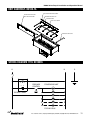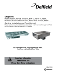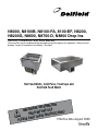
1
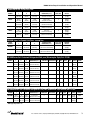
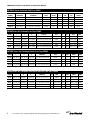
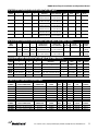
N8000, N8100B, N8100-FA, 8100-EF, N8200, N8200G, N8600, N8700-D, N8800 Drop Ins Service, Installation and Care Manual Please read this manual completely before attempting to install or operate this equipment! Notify carrier of damage! Inspect all components immediately. See page 2. Hot Food Wells, Cold Pans, Frost tops and Hot/Cold Food Wells TION A M R O T INF N A T R O USE IMP E R O F E ONS! I T C READ B U R INST E S E H T AVE S E S A Effective Date August 2006 E PL N8000 Series Drop-In Installation and Operation Manual Contents RECEIVING AND INSPECTING UNIT................................... 2 MECHANICAL DATA.......................................................... 3-5 INSTALLATION N8000, N8000N, N8100B, N8100NB, N8200, N8200G, 8100-FA, 8100-EF Series..................................................... 6 N8700D, N8700N, & N8800 Series...................................... 6 N8600 Series........................................................................ 7 OPERATION N8100B, N8100NB............................................................... 7 N8100-FA............................................................................. 8 N8200 & N8200G................................................................. 8 N8700D, N8700N, & N8800 Series................................... 8-9 8100-EF................................................................................ 9 N8600................................................................................. 10 ROUTINE MAINTENANCE.................................................. 10 UNIT ASSEMBLY N8100-FA............................................... 11 WIRING DIAGRAM N8100-FA........................................................................... 11 N8100B, N8100NB, N8200, N8200G & N8800.................. 12 N8700N & N8700D............................................................. 13 N8600............................................................................ 14-15 8100-EF & 8100-EFN......................................................... 16 LOUVER DIAGRAM............................................................. 17 MISC PARTS........................................................................ 17 N8100-FA REPLACEMENT PARTS LIST............................ 18 CONDENSING UNIT ASSEMBLY PARTS LIST............. 19-22 FOOD WELL ASSEMBLY PARTS LIST......................... 23-25 STANDARD WARRANTIES............................................ 26-27 Serial Number Location The serial number on self-contained refrigerated units is on the electrical specifications tag located near the condensing unit. The serial number on remote refrigerated units is on the outside bottom of the food well. On hot food pans and hot/cold combination pans, the serial number tag is located on the back of the control raceway or remote panel. The serial number tag also lists the refrigerant used and the amount of charge. Always have the serial number of your unit available when calling for parts or service. This manual covers only standard 8000 series units. If you have a custom designed unit, you should contact our parts/service department for questions. ©2006 The Delfield Company. All rights reserved. Reproduction without written permission is prohibited. “Delfield” is a registered trademark of The Delfield Company. Receiving and Inspecting the Equipment Even though most equipment is shipped crated, care should be taken during unloading so the equipment is not damaged while being moved into the building. 1. Visually inspect the exterior of the package and skid or container. Any damage should be noted and reported to the delivering carrier immediately. 2. If damaged, open and inspect the contents with the carrier. 3. In the event that the exterior is not damaged, yet upon opening, there is concealed damage to the equipment notify the carrier. Notification should be made verbally as well as in written form. 4. Request an inspection by the shipping company of the damaged equipment. This should be done within 10 days from receipt of the equipment. 5. Also open the compressor compartment housing and visually inspect the refrigeration package. Be sure lines are secure and base is still intact. 6. Freight carriers can supply the necessary damage forms upon request. 7. Retain all crating material until an inspection has been made or waived. Uncrating the Equipment First cut and remove the banding from around the crate. Remove the front of the crate material, use of some tools will be required. For customer service, call (800) 733-8829, (800) 733-8821, Fax (989) 773-3210, www.delfield.com N8000 Series Drop-In Installation and Operation Manual N8000 N8000Series SeriesIce IceCooled CooledCold ColdPans Pans MODEL NUMBER L D H counter CUTOUT DIMENSIONS (D x L) # OF 12” X 20” PANS HELD SHIPPING WEIGHT N8018 18” (45.7cm) 26” (66cm) 10.75 (27.3cm) 17” x 25” 1 (43.2cm x 63.5cm) 37 lbs (17 kg) N8030 30.75” (78.1cm) 26” (66cm) 10.75 (27.3cm) 29.75” x 25” 2 (75.6cm x 63.5cm) 100 lbs (45 kg) N8043 43.5” (110.5cm) 26” (66cm) 10.75 (27.3cm) 42.50” x 25” 3 (107.9cm x 63.5cm) 118 lbs (53 kg) N8056 56.25” (142.9cm) 26” (66cm) 10.75 (27.3cm) 55.25” x 25” 4 (140.3cm x 63.5cm) 145 lbs (65 kg) N8069 69” (175.3cm) 26” (66cm) 10.75 (27.3cm) 68” x 25” 5 (172.7cm x 63.5cm) 164 lbs (74 kg) N8081 81.75” (208cm) 26” (66cm) 10.75 (27.3cm) 80.75” x 25” 6 (205.1cm x 63.5cm) 190 lbs (86 kg) N8000N Series Ice Cooled Cold Pans - narrow line MODEL NUMBER L D H counter CUTOUT DIMENSIONS (D x L) # OF 12” X 20” PANS HELD SHIPPING WEIGHT N8046N 46.75” (118.75 cm) 18.0” (45.72cm) 10.75” (27.3cm) 17” x 45.75” 2 (43.18 cm x 116.20 cm) 100 lbs (46 kg) N8068N 67.5” (171.5cm) 18” (45.72cm) 10.75” (27.3cm) 17” x 66.50” 3 (43.18 cm x 168.91 cm) 120 lbs (55 kg) N8100B Series Self-Contained Refrigerated Cold pans (Bloomington Style) Ref. R134A MODEL NUMBER L D H COUNTER CUTOUT DIMENSIONS (D x L) # OF 12” x 20” VOLTAGE PANS HELD HERTZ/PHASE H.P. AMPS BTU LOAD SYS. SHIPPING REF CAP. WEIGHT CHARGE N8118B 18” 26” 21.87” (45.7cm) (66.04cm) (55.5cm) 115/60/1 17” X 25” 1 1/5 4.0 204 708 (43.2cm x 63.5cm) 103 lbs (46 kg) 8.0oz N8130B 30.75” 26” 21.87” (78.1cm) (66.04cm) (55.5cm) 29.75” x 25” 2 115/60/1 1/5 4.0 379 812 (75.6cm x 63.5cm) 161 lbs (72 kg) 8.0oz N8143B 115/60/1 43.5” 26” 21.87” 42.50” X 25” 3 1/5 4.0 569 889 (110.5cm) (66.04cm) (55.5cm) (108.58cm x 63.5cm) 184 lbs (83 kg) 8.0oz N8156B 56.25” 26” 21.87” (142.9cm) (66.04cm) (55.5cm) 55.25” x 25” 4 115/60/1 1/4 7.0 758 1373 233 lbs (140.3cm x 63.5cm) (105 kg) 16.0oz N8169B 69” 26” 21.87” (175.3cm) (66.04cm) (55.5cm) 68” X 25” 5 115/60/1 1/4 7.0 948 1469 243 lbs (172.7cm x 63.5cm) (109 kg) 16.0oz N8181B 81.75” 26” 21.87” (208cm) (66.04cm) (55.5cm) 80.75” x 25” 6 115/60/1 1/3 8.0 1138 1921 260 lbs 12.0 oz (205.1cm x 63.5cm) (117 kg) * NEMA plug configuration 5-15P N8100NB Series Self Contained Refrigerated Cold pans (Bloominton Style Narrow) Ref. R134A MODEL NUMBER L H D COUNTER CUTOUT # OF 12” x 20” VOLTAGE DIMENSIONS (D x L) PANS HELD HERTZ/PHASE H.P. AMPS BTU LOAD SYS. SHIPPING CAP. WEIGHT REF. CHARGE 115/60/1 1/5 4.0 46.75” 18” 21.81” 17” X 45.75” 2 454 680 175 lbs N8146NB (118.7cm) (45.7cm) (55.4cm) (43.2cm x 113.7cm) (80 kg) 8.0oz N8168NB 12.0oz 67.5” 18” 21.81” 17” x 66.5” 3 115/60/1 1/5 4.0 676 804 240 lbs (171.5cm) (45.7cm) (55.4cm) (43.2cm x 168.9cm) (109 kg) * NEMA plug configuration 5-15P For customer service, call (800) 733-8829, (800) 733-8821, Fax (989) 773-3210, www.delfield.com N8000 Series Drop-In Installation and Operation Manual N8100-FA Series Air Curtain Cold Pans-R404A MODEL NUMBER COUNTER CUTOUT DIMENSIONS LOUVER CUTOUT DIMENSIONS VOLTZ/HERTZ PHASE SHIP WEIGHT H.P. AMP BTU REFRIG. CHARGE N8131-FA 30.2” x 25.5” 22” (55.8cm) x 11” (27.9cm) 115/60/1 165 N8144-FA 42.95” x 25.5” 22” (55.8cm) x 11” (27.9cm) 115/60/1 175 1/4 8.0 2154 16.0 oz. 1/2 10.0 3142 32.0 oz. N8157-FA 55.7” x 25.5” 22” (55.8cm) x 11” (27.9cm) 115/60/1 N8169-FA 68.45” x 25.5” 22” (55.8cm) x 11” (27.9cm) 115/60/1 225 1/2 10.0 3806 32.0 oz. 235 3/4 15.0 5545 48.0 oz. N8182-FA 81.2” x 25.5” 22” (55.8cm) x 11” (27.9cm) 115/60/1 255 3/4 15.0 5545 48.0 oz. Tops N8200 Series Self-Contained Frost Tops-R404A MODEL NUMBER L D H COUNTER CUTOUT DIMENSIONS VOLTS/HERTZ/ PHASE H.P. AMPS SHIP WEIGHT REF. CHARGE N8231 31.75" (80.6cm) 26”(66cm) 15.75” (40cm) 30.75” x 25" (78.1cm x 63.5cm) 115/60/1 1/4 7.0 170 lbs (77 kg) 12.0oz N8245 45.62” (115.9cm) 26”(66cm) 15.75” (40cm) 44.63” x 25” (113.3cm x 63.5cm) 115/60/1 1/4 7.0 185 lbs (83 kg) 12.0oz N8259 59.5” (151.1cm) 26”(66cm) 15.75” (40cm) 58.50” x 25” (148.59cm x 63.5cm) 115/60/1 1/4 7.0 213 lbs( 96 kg) 12.0oz N8273 73.37" (186.4cm) 26”(66cm) 15.75” (40cm) 72.38” x 25” (183.84cm x 63.5cm) 115/60/1 1/3 8.0 218 lbs (98 kg) 24.0oz N8287 87.25" (221.6cm) 26”(66cm) 15.75” (40cm) 86.25" x 25" (219.07cm x 63.5cm) 115/60/1 1/3 8.0 224 lbs (101 kg) 24.0oz * NEMA plug configuration 5-15P Tops N8200G Series Self Contained Granite Frost Tops-R404A MODEL NUMBER L D H COUNTER CUTOUT DIMENSIONS VOLTS/HERTZ/ PHASE H.P. AMPS SHIP WEIGHT REF CHARGE N8231G 31.75” (80.6cm) 25.87”(65.7cm) 19” (48.3cm) 30.75” X 25” (78.10cm x 63.5cm) 115/60/1 1/4 7.0 219lbs. 12.0 oz N8245G 45.62” (115.9cm) 25.87”(65.7cm) 19” (48.3cm) 44.63” x 25” (113.36cm x 63.5cm) 115/60/1 1/4 7.0 284lbs. 12.0 oz N8259G 59.5” (151.1cm) 25.87”(65.7cm) 19” (48.3cm) 58.5” x 25” (148.6cm x 63.5cm) 115/60/1 1/3 8.0 338lbs. 24.0 oz N8273G 73.37” (186.4cm) 25.87”(65.7cm) 19” (48.3cm) 72.38” x 25” (183.84cm x 63.5cm) 115/60/1 1/2 9.0 425lbs. 32.0 oz. AMPS SHIP WEIGHT REF CHARGE 1/4 24.0 164 lbs (81 kg) 16.0 oz 16.0 oz * NEMA plug configuration 5-15P N8600 Series Self Contained Combination Hot/Cold Food Wells Wells-R404A MODEL NUMBER L D H COUNTER CUTOUT DIMENSIONS # OF VOLTS/HERTZ/ PANS PHASE H.P. N8630 30.75” (78.1cm) 26”(66cm) 23.75” (60.3cm) 29.75” X 25” (75.5cm x 63.5cm) 2 N8643 120/60/1 43.5” (110.5cm) 26”(66cm) 23.75” (60.3cm) 42.50” x 25” (107.9cm x 63.5cm) 3 120/208 or 120/240 1/4 21.0 198 lbs (95 kg) N8656 56.25” (142.9cm) 26”(66cm) 23.75” (60.3cm) 55.25” x 25” (140.3cm x 63.5cm) 4 120/208 or 120/240 1/4 21.0 233 lbs (113 kg) 16.0 oz N8669 5 120/208 or 120/240 1/4 43.0 266 lbs (102 kg) 24.0 oz 6 120/208 or 120/240 1/3 43.0 301 lbs (136 kg) 24.0 oz 69” (175.3cm) 26”(66cm) 23.75” (60.3cm) 68” x 25” (172.7cm x 63.5cm) N8681 81.75” (207.6cm) 26”(66cm) 23.75” (60.3cm) 80.75” x 25” (205.1cm x 63.5cm) For customer service, call (800) 733-8829, (800) 733-8821, Fax (989) 773-3210, www.delfield.com N8000 Series Drop-In Installation and Operation Manual N8700D Series Individually Controlled Electric Hot Food Wells MODEL NUMBER L D H N8717-D 17.88” (45.4cm) 26.00 (66cm) 9.5” (24cm)* N8731-D 31.75” (80.6cm) 26.00 (66cm) 9.5” (24cm)* N8745-D 45.63” (115.9cm) 26.00 (66cm) 9.5” (24cm)* N8759-D 59.5” (151.1cm) 26.00 (66cm) 9.5” (24cm)* N8773-D 73.38” (186.4cm) 26.00 (66cm) 9.5” (24cm)* N8787-D 87.25” (221.4cm) 26.00 (66cm) 9.5” (24cm)* *14” Overall to drain connection COUNTER CUTOUT DIMENSIONS CONTROL PANEL CUTOUT DIMENSIONS # OF WELLS VOLTS/HERTZ/ PHASE AMPS SHIP WEIGHT 16.88” X 25” (42.87cm x 63.5cm) 30.75” x 25” (78.10cm x 63.5cm) 44.63” x 25” (113.36cm x 63.5cm) 58.5” x 25” (148.59cm x 63.5cm) 72.38” x 25” (183.84cm x 63.5cm) 86.25” x 25” (219.07cm x 63.5cm) 4.62” x 7” (11.7cm x 17.8cm) 4.62” x 10.31” (11.7cm x 26.2cm) 4.62” x 14.5” (11.7cm x 36.8cm) 4.62” x 18.69” (11.7cm x 47.5cm) 4.62” x 22.88” (11.7cm x 58.1cm) 4.62” x 27” (11.7cm x 68.6cm) 1 120/60/1 8.3 39 lbs (17 kg) 2 120/60/1 16.7 119 lbs (54 kg) 3 208-230/60/1 14.4/15.9 150 lbs (68 kg) 4 208-230/60/1 19.2/21.3 170 lbs (77 kg) 5 208-230/60/1 24.0/26.6 196 lbs (88 kg) 6 208-230/60/1 28.8/31.9232 lbs (104 kg) N8700N Series Individually Controlled Electric Hot Food Wells (with remote control) MODEL NUMBER L D H COUNTER CUTOUT DIMENSIONS (DXL) CONTROL PANEL CUTOUT DIMENSIONS # OF FOOD WELLS VOLTAGE HERTZ/PHASE AMPS SHIPPING WEIGHT N8746N 45.61” (116cm) 15.87” (40cm) 9.5” (24cm) 15” X 44.61” 4.62” X 10.31” 2 120/60/1 16.7 (38.1 cm X 113.3 cm) (11.7 cm x 26.19 cm) 100 lbs (46 kg) N8768N 67.48” (172cm) 15.87” (40cm) 9.5” (24cm) 15.” X 66.48” 4.62” x 14.50” 3 208-230/60/1 14.4/ 15.9 (38.1 cm X 169 cm) (11.7 cm x 36.83 cm) 130 lbs (59 kg) N8800 Series Single Tank Electric Hot Food Wells (with remote control) MODEL NUMBER A D H COUNTER CUTOUT DIMENSIONS # OF 12” X 20” VOLTS/HERTZ/ PANS HELD PHASE AMPS SHIP WEIGHT 16.7 124lbs(56kg) N8831 31.75” (80.6cm) 26” (66cm) 11” (27.9cm) 30.75” X 25” (78.10cm x 63.5cm) 2 N8845 45.63” (115.9cm) 26” (66cm) 11” (27.9cm) 44.63” x 25” (113.36cm x 63.5cm) 3 208-230/60/1 14.4/15.9 150lbs(68kg) N8859 59.5” (151.1cm) 26” (66cm) 11” (27.9cm) 58.5” x 25” (148.59cm x 63.5cm) 4 208-230/60/1 19.2/21.3 189lbs(85kg) N8873 73.38” (186.4cm) 26” (66cm) 11” (27.9cm) 72.38” x 25” (183.84cm x 63.5cm) 5 208-230/60/1 24.0/26.6 200lbs(91kg) N8887 87.25 (221.6cm) 26” (66cm) 11” (27.9cm) 86.25” x 25” (219.07cm x 63.5cm) 6 208-230/60/1 28.8/31.3 226lbs(102kg) 120/60/1 8100-EF Series LiquiTec® Cold Pans-R404A MODEL NUMBER COUNTER CUTOUT DIMENSIONS LOUVER CUTOUT VOLTZ/HERTZ REMOTE SHIP WEIGHT REFRIG. DIMENSIONS PHASE AMPS H.P. BTU LBS CHARGE 8118-EF 17.5” x 25.2” (44.45cm x 64cm)22” x 11” 115/60/1 7.0 1/4292200/9124.0 oz. 8132-EF 31” x 25.2” (78.74cm x 64cm)22” x 11” 115/60/1 7.0 1/4 379225/10224.0 oz. 8145-EF 44.5” x 25.2” (113cm x 64cm)22” x 11” 115/60/1 7.0 1/4 569235/10724.0 oz. 8159-EF 58” x 25.2” (147.3cm x 64cm)22” x 11” 115/60/1 7.0 1/4 758285/13024.0 oz. 8172-EF 71.5” x 25.2” (181.6cm x 64cm)22” x 11” 115/60/1 7.0 1/4 948295/13424.0 oz. 8186-EF 85.2” x 25.2” (216.4cm x 64cm)22” x 11” 115/60/1 7.0 1/4 1138 SLIM LINE MODELS MODEL COUNTER NUMBER CUTOUT DIMENSIONS LOUVER CUTOUT VOLTZ/HERTZ DIMENSIONS PHASE AMPS H.P. NEMA PLUG 306/13924.0 oz. SHIP WEIGHT REFRIG. LBS/KG CHARGE 8148-EFN 44.5” x 25.2” (113cm x 64cm)22” x 11” 115/60/1 7.0 1/4 5-15P235/10724.0 oz. 8169-EFN 58” x 25.2” (147.3cm x 64cm)22” x 11” 115/60/1 7.0 1/4 5-15P285/13024.0 oz. 8191-EFN 71.5” x 25.2” (181.6cm x 64cm)22” x 11” 115/60/1 7.0 1/4 5-15P295/13424.0 oz. For customer service, call (800) 733-8829, (800) 733-8821, Fax (989) 773-3210, www.delfield.com N8000 Series Drop-In Installation and Operation Manual Installation N8000, N8000N, N8100B, N8100NB, N8200, N8200G, N8100-FA & 8100-EF Series Drop In Procedure These units are intended for indoor use only. A room temperature of not more than 86°F (30°C) is recommended. Reinforce the counter as necessary to provide maximum loading. CAUTION Some N8000, N8000N, N8100B and N8100NB may have poyethylene insulation in the drain hole. This can easily be cut out without any contact or damage to the units interior insulation or refrigeration lines. Unit requires that the sides and bottom are not any closer than 3” to any combustible material. DANGER The counter cut-out sizes and power requirements are shown on pages 3-5. A gasket is installed in the flange of each unit. The weight of the unit on the gasket forms a seal preventing liquids from seeping into the cut-out opening. Louvers Self-contained refrigerated units (N8100, N8200 and N8200G Series) require airflow to the compressor. A 13” x 25” louver is (33 cm x63.5 cm) provided by Delfield and must be installed in the counter in front of the condenser. See specifications on page 3 for louver cutout dimensions. The rear must have an opening to permit removal of heated air. The opening must be at least 8” x 11”, a total of 88 square inches (20.3 cm x 27.9 cm, a total of 566 square centimeters). Moisture collecting from improper drainage can create a slippery surface on the floor and a hazard to employees. It is the owner’s responsibility to provide a container or outlet for drainage. Electrical connection Refer to the amperage data on pages 3-5, the serial tag or your local code to be sure the unit is connected to the proper power source. A protected circuit of the correct voltage and amperage must be run for connection of the line cord. Some units have an “ON/OFF” switch located behind the louvered panel in the machine compartment. Simply turn the switch to “ON” to begin operation. Some units have an “OFF” position on the switch which is located behind the louvered panel in the machine compartment. Simply turn the dial to begin operation. Plumbing The unit must be disconnected from the power source whenever performing service or maintenance functions. The unit’s drain must have an outlet to an appropriate drainage area or container. N8200 series have 1/2” drain and N8200G series have 3/4” drain located on end/center. The 1” diameter drain on N8000, N8100, 8100FA and 8100EF Series units is shipped loose and must be connected during installation. Never operate the unit without the louvered panel in place! Installation N8700D, N8700N, & N8800 Series Drop In Procedure These units are intended for indoor use only. Reinforce the counter as necessary to provide maximum loading. Unit requires that the sides and bottom are not any closer than 3” to any combustible material. DANGER The counter cut-out sizes and power requirements are shown on pages 3-5. A gasket is installed in the flange of each unit. The weight of the unit on the gasket forms a seal preventing liquids from seeping into the cut-out opening. N8700-D Series pans should be installed with the drains at the back, away from the operator’s sides. N8700N Series have drains located in the front - operator side. The controls on N8700-D and N8800 Series units are mounted in a control panel, designed to be installed at a “remote” location. The control panel should be installed so that the indicator light for each control is above the control. N8700 & N8700N Series units have 48” (121.9cm) of conduit and N8800 Series units have 24” (61.0cm) of conduit between the pans and the remote control panel to facilitate this installation. Plumbing N8700-D and N8700N Plumbing: Unit is equipped with 1/2” drains, (one per well located in right rear corner 1/2” female N.P.T.) manifold and 1/2” gate valve. N8800 Plumbing: Well is sloped to a 1.00” female N.P.T. stainless steel drain. CAUTION Moisture collecting from improper drainage can create a slippery surface on the floor and a hazard to employees. It is the owner’s and operator’s responsibility to provide a container or outlet for drainage. Electrical connection Refer to the amperage data on pages 3-5, the serial tag or your local code to be sure the unit is connected to the proper power source. The unit must be disconnected from the power source whenever performing service or maintenance functions. For customer service, call (800) 733-8829, (800) 733-8821, Fax (989) 773-3210, www.delfield.com N8000 Series Drop-In Installation and Operation Manual Installation N8600 Drop In Procedure These units are intended for indoor use only. A room temperature of not more than 86°F (30°C) is recommended. Reinforce the counter as necessary to provide for maximum loading. Unit requires that the sides and bottom are not any closer than 3” to any combustible material. DANGER The counter cut-out sizes and power requirements are shown on pages 3-5. A gasket is installed in the flange of each unit. The weight of the unit on the gasket forms a seal preventing liquids from seeping into the cut-out opening. The cut-out dimensions for the control box on N8600 Series units is 4.25” x 12.25” (10.8 cm x 31.1 cm). Louvers For proper refrigerated operation, N8600 Series units require airflow to the compressor. A 13” x 25” louver is (33.0 cm x 63.5 cm) is provided by Delfield and must be installed in the counter in front of the condenser. See page 3 & 4 for louver cut-out dimensions. The rear must have an opening to permit removal of heated air. The opening must be at least 8” x 11”, a total of 88 square inches (20.3 cm x 27.9 cm, a total of 566 square centimeters). Plumbing The unit’s 1” drain must have an outlet to an appropriate drainage area or container. CAUTION Moisture collecting from improper drainage can create a slippery surface on the floor and a hazard to employees. It is the owner’s and operator’s responsibility to provide a container or outlet for drainage. Electrical connection Refer to the amperage data on page 3-5, the serial tag or your local code to be sure the unit is connected to the proper power source. The unit must be disconnected from the power source whenever performing service or maintenance functions. Never operate the unit without the louvered panel in place! Operation - N8100N, N8100NB N8100 Series cold pans are adjusted at the factory to provide satisfactory operation without any further adjustments. However, if it is necessary to adjust the temperature, the control is located in the machine compartment. Turn the knob clockwise as indicated on the control. Settings are from 1 thru 7 (7 being the coldest). Adjustments should be made gradually. Several small adjustments will be more effective than one large adjustment. It may take an hour or longer to realize the temperature change depending on the application and location of the unit. These units are not designed to cool warm food products. Items should be placed in the unit pre-cooled at least to the desired holding temperature, if not slightly colder. In some applications, a gradual warming of product may occur, particularly at the exposed top of the product. Stirring or rotation of the product may be necessary to maintain overall temperature. Warming of food product can occur very quickly outside of the unit. When loading or rotating product, avoid leaving food items in a non-refrigerated location for any length of time to prevent warming or spoilage. The temperature control is used to turn the unit on and off as well as control the temperature of the cold pan. The settings range from 1 through 7 (7 being the coldest). To turn the cold pan off, turn the knob to the off position. If the cold pan is to be used with ice, it is recommended that the optional perforated bottoms be used. These will allow ice to melt properly. For customer service, call (800) 733-8829, (800) 733-8821, Fax (989) 773-3210, www.delfield.com AND#40."3ERIES3ERVICEAND)NSTALLATION-ANUAL 2%&2)'%2!.4#(!2'%3!.$02%3352%#/.42/,3%44).'3 2EFRIGERANT#HARGES&OR3ERIES5NITS N8000 Series Drop-In Installation and Operation Manual 04"OZ 04"OZ 04"OZ 04"OZ All Delfield refrigerated models come equipped with 115-volt, 60 04"OZ OZ cycle, single phase refrigeration units. 04" The refrigeration valves- Operation -N8100-FA "5# OZ "5# OZ 2UBY4UESDAY3ALAD"AR3ERVICEAND)NSTALLATION-ANUAL "5# OZ "5# OZ $%&2/344)-%2 Defrost Timer "5# OZ Every 4 hours for 20 minutes. "5# OZ are open and ready to operate as soon as the power supply 2EFRIGERANT#HARGES&OR#40."3ERIES5NITS cord is plugged into the standard 115-volt, grounded electrical outlet. #40." OZ Pressure Control #40." OZ #40." OZ The temperature is controlled by an adjustable pressure control located in the machine compartment. and adjustable control has the 02%3352%#/.42/,3%44).'3 word COLDER near the knob, with an arrow to indicate the adjustment direction. These controls are0RESSURE#ONTROL3ETTINGS field adjustable and do not require a ser4HEFACTORYRECOMMENDEDLOWPRESSURECONTROLSETTINGSFOR04"SARECUTINANDCUTOUTTOMAINTAIN vice agent. If you have any questions, feel fre to contact the Delfield PROPERTEMPERATUREFORPRODUCTINTHERAIL4HEINTERIORTEMPERATUREISCONTROLLEDBYTHETHERMOSTATMOUNTEDONTHE Service Department. EVAPORATORCOILHOUSING 4HEFACTORYRECOMMENDEDLOWPRESSURECONTROLSETTINGSFOR"5#SARECUTINANDCUTOUTTOMAINTAIN PROPERTEMPERATURE In attempting to adjust the pressure control, you can do damage to the unit by accidentally adjusting the differential. Please make small incremental adjust!LL$ELFIELDREFRIGERATEDMODELSCOMEEQUIPPEDWITH VOLTCYCLESINGLEPHASEREFRIGERATIONUNITS4HE ments if a temperature adjustment is necessary, REFRIGERATIONVALVESAREOPENANDREADYTOOPERATEASSOON please contactASTHEPOWERSUPPLYCORDISPLUGGEDINTOTHESTANDARD the service department at Delfield (800) 733-8821VOLTGROUNDEDELECTRICALOUTLET or your local servic agent. Delfield is not responsible for charges incurred while having 0RESSURE#ONTROL 4HETEMPERATUREISCONTROLLEDBYANADJUSTABLEPRESSURE the pressure control adjusted. CONTROLLOCATEDINTHEMACHINECOMPARTMENT!NADJUSTABLE CONTROLHASTHEWORD#/,$%2NEARTHEKNOBWITHANARROW TOINDICATETHEADJUSTMENTDIRECTION4HESECONTROLSARE Food in the N8100-FA pans should not be FIELDADJUSTABLEANDDONOTREQUIREASERVICEAGENT)FYOU loaded in such a way as to interfere with the air HAVEANYQUESTIONSFEELFREETOCONTACTTHE$ELFIELD3ERVICE $EPARTMENT curtain flowing over the cold pans. ) NATTEMPTINGTOADJUSTTHEPRESSURECONTROL YOUCANDODAMAGETOYOURUNITBYACCIDENTALLY ADJUSTINGTHEDIFFERENTIAL0LEASEMAKESMALL INCREMENTALADJUSTMENTSIFATEMPERATURE ADJUSTMENTISNECESSARYPLEASECONTACTTHE SERVICEDEPARTMENTAT$ELFIELD ORYOURLOCALSERVICEAGENT$ELFIELDISNOT tops are designed to maintain an RESPONSIBLEFORCHARGESINCURREDWHILEHAVING THEPRESSURECONTROLADJUSTED Operation - N8200, N8200G 17 differential 25 cut-in, 8 cut-out &ORCUSTOMERSERVICECALL&AXWWWDELlELDCOM Since it takes some time for the frost to accumulate initially, the N8200 & N8200G Series frost unit should be turned on approximately one hour before it is even layer of frost to pleasantly display product. Once turned actually required. Product should not be placed on the frost top on, the compressor will run continuously. The unit should be prior to turning the unit on,ELDCOM because it may freeze to the surface &ORCUSTOMERSERVICECALL&AXWWWDELl turned off overnight or when not in use. There is no temperaof the unit. ture control on the N8200 series. The ON/OFF switch is the only means available to cycle the unit. Operation N8700D, N8700N & N8800 Series These units are designed to hold warm food product between 140˚F to 160˚F (60˚C to 71˚C). N8700D, and N8700N Series individually heated hot food units may be operated “wet” (with water in the wells) or “dry”. However, “wet” operation is usually recommended for better performance. N8800 Series single tank hot food units are designed to be operated “wet” (with water in the tank) only. Proper water level (approximately two inches) must be maintained to prevent damage to the tank on the N8800 Series units. After the unit is hard wired to the electrical system, select desired temperature by rotating temperature control. A knob and indicator light are provided for each individual heated food well. First Time Use Before the unit is used the first time for serving, turn the temperature knob to “HI” and heat the well for 20 to 30 minutes. Any residue or dust that adhered to the heater element(s) will be burned off during this initial preheat period. When serving thick sauces always use the hot food well in “wet” operation. This provides more uniform temperature for the sauce. Never place food directly in well. Always use pans. For most efficient operation, keep covered inserts in each well during preheating or when empty. Always place covers on pans when not serving to prevent food from drying out. If the same temperature settings for each well are used everyday, the temperature knobs can be left in their set position and the wells can be turned off by using the ON/OFF switch at the end of the control panel. For customer service, call (800) 733-8829, (800) 733-8821, Fax (989) 773-3210, www.delfield.com 2EFRIGERANT#HARGES&OR3ERIES5NITS 04"OZ "5# OZ Drop-In Installation and Operation Manual 04"OZN8000 Series "5# OZ 04" OZ "5# OZ Operation N8700D, N8700N & N8800 Series 04"OZ "5# OZ Wet Operation 04"OZ Dry Operation "5# N8700 OZ Series only Fill the food well with a minimum of 2” of water and cover is usually much more efficient and is usually 04"OZ Wet operation "5# OZ with lid or empty pan. To preheat water, set temperature preferred. However, these units may be operated without water control at “HI”. With pans in place, wells will boil water. Food with no damage to the unit. temperature will vary depending on type and amount of product. To minimize steam and water usage, set control at lowest 2EFRIGERANT#HARGES&OR#40."3ERIES5NITS When operated dry, the bottom of the well will discolor. To setting that will maintain proper food temperature. To reduce clean, use a stainless steel cleaner or mild abrasive. preheating time, use hot water to fill the well. #40." OZ The dry well should never be preheated longer than 15 minutes. Only 6” deep pans should be used with dry food well. #40." OZ When operating these units “wet,” never use #40." OZ anything other than plain water in the wells or tank. Failure to observe this warning may result in personal injury or damage to the unit. When operated at the highest temperature 02%3352%#/.42/,3%44).'3 setting, the top of the unit will become very hot. Staff and customers using the equipment should be informed about this. 0RESSURE#ONTROL3ETTINGS When operated dry, the well bottoms become very hot. Do not allow unprotected skin to contact any well surface. DANGER DANGER Steam can cause serious burns. Always use 4HEFACTORYRECOMMENDEDLOWPRESSURECONTROLSETTINGSFOR04"SARECUTINANDCUTOUTTOMAINTAIN some type of protective covering on your hands PROPERTEMPERATUREFORPRODUCTINTHERAIL4HEINTERIORTEMPERATUREISCONTROLLEDBYTHETHERMOSTATMOUNTEDONTHE and arms when removing lids from the unit. Lift DANGER EVAPORATORCOILHOUSING the lid in a way that will direct escaping steam away from your face and body. 4HEFACTORYRECOMMENDEDLOWPRESSURECONTROLSETTINGSFOR"5#SARECUTINANDCUTOUTTOMAINTAIN PROPERTEMPERATURE Operation 8100-EF Series 8100-EF Series cold pans are adjusted at the factory to !LL$ELFIELDREFRIGERATEDMODELSCOMEEQUIPPEDWITH provide satisfactory operation without any further adjustVOLTCYCLESINGLEPHASEREFRIGERATIONUNITS4HE ments. However, if it is necessary to adjust the temperature, REFRIGERATIONVALVESAREOPENANDREADYTOOPERATEASSOON the control is located in the machine compartment. Turn the ASTHEPOWERSUPPLYCORDISPLUGGEDINTOTHESTANDARD knob clockwise as indicated on the control. Settings are from VOLTGROUNDEDELECTRICALOUTLET 1 through 7; 7 being the coldest. Adjustments should be made gradually. Several small adjustments will be more effective It may take an hour or longer to realize the temperature change depending on the application 4HETEMPERATUREISCONTROLLEDBYANADJUSTABLEPRESSURE and location of the unit. than one large adjustment. 0RESSURE#ONTROL CONTROLLOCATEDINTHEMACHINECOMPARTMENT!NADJUSTABLE CONTROLHASTHEWORD#/,$%2NEARTHEKNOBWITHANARROW These units are not designed to cool warm food products. TOINDICATETHEADJUSTMENTDIRECTION4HESECONTROLSARE Items should be placed in the unit pre-cooled at least to the desired holding temperature, if not slightly colder. In some FIELDADJUSTABLEANDDONOTREQUIREASERVICEAGENT)FYOU applications, a gradual warming of product may occur, particuHAVEANYQUESTIONSFEELFREETOCONTACTTHE$ELFIELD3ERVICE larly at the exposed top of the product. Stirring or rotation of $EPARTMENT the product may be necessary to maintain overall temperature. Warming of food product can occur very quickly outside of the unit. When loading or rotating the product, avoid leaving food )NATTEMPTINGTOADJUSTTHEPRESSURECONTROL items in a non-refrigerated location for any length of time to YOUCANDODAMAGETOYOURUNITBYACCIDENTALLY prevent warming or spoilage. ADJUSTINGTHEDIFFERENTIAL0LEASEMAKESMALL The cold pan is not intended to be used with ice. INCREMENTALADJUSTMENTSIFATEMPERATURE ADJUSTMENTISNECESSARYPLEASECONTACTTHE SERVICEDEPARTMENTAT$ELFIELD ORYOURLOCALSERVICEAGENT$ELFIELDISNOT RESPONSIBLEFORCHARGESINCURREDWHILEHAVING THEPRESSURECONTROLADJUSTED 17 differential 25 cut-in, 8 cut-out &ORCUSTOMERSERVICECALL&AXWWWDELlELDCOM For customer service, call (800) 733-8829, (800) 733-8821, Fax (989) 773-3210, www.delfield.com N8000 Series Drop-In Installation and Operation Manual Operation N8600 Hot/Cold Series Hot Operation To assure maximum compressor life, do not switch from “hot” to “cold” operation without allowing a cool down period. Never switch from hot to cold operation while hot water remains in the pans. Failure to observe this warning will greatly reduce compressor life and eventually cause premature compressor failure. N8600 Series hot and cold combination pans must be operated with water in the well for proper hot operation. Fill well with a minumum of 4” of water. Place function switch in HOT position. Turn thermostat dial to highest position and allow unit to warm up. Then reset the thermostat to maintain the desired temperature. When operating these units “wet,” never use anything other than plain water in the wells or tank. Failure to observe this warning may result in personal injury or damage to the unit. DANGER When operated at the highest temperature setting, the top of the unit will become very hot. Staff and customers using the equipment should be informed about this. To turn unit off, simply move the function switch to OFF position. Drain water and allow unit to cool before cleaning or switching to cold operation. Switching from hot to cold operation STEPS Follow this procedure: 1) Place the function switch in the OFF position and drain off hot water. 2) Allow the unit to cool until it can be safely cleaned. 3) When clean up procedures are complete, unit will be ready for cold operation. This takes about 1 hour. Cold Operation Simply place the function switch to the COLD position. The compressor controller has been factory set and no temperature adjustment should be necessary. If the cold pan is to be used with ice, it is recommended that the optional perforated bottoms be used. These will allow ice to melt properly. Switching from cold to hot operation No special procedure is required to switch from the cold to hot operation. Be certain to fill will with a minimum of 4” of water. The unit is designed so that the compressor and the heating elements cannot operate at the same time. Continued operation of the compressor in the “hot position” should not be considered normal. Call for service if this happens. Routine Maintenance Stainless Steel Care and Cleaning To prevent discoloration or rust on stainless steel several important steps need to be taken. First, we need to understand the properties of stainless steel. Stainless steel contains 70- 80% iron, which will rust. It also contains 12-30% chromium, which forms an invisible passive film over the steels surface, which acts as a shield against corrosion. As long as the protective layer is intact, the metal is still stainless. If the film is broken or contaminated, outside elements can begin to breakdown the steel and begin to form rust of discoloration. Proper cleaning of stainless steel requires soft cloths or plastic scouring pads. NEVER USE STEEL PADS, WIRE BRUSHES OR SCRAPERS! Cleaning solutions need to be alkaline based or non-chloride cleaners. Any cleaner containing chlorides will damage the protective film of the stainless steel. Chlorides are also commonly found in hard water, salts, and household and industrial cleaners. If cleaners containing chlorides are used be sure to rinse repeatedly and dry thoroughly upon completion. Routine cleaning of stainless steel can be done with soap and water. Extreme stains or grease should be cleaned with a non-abrasive cleaner and plastic scrub pad. It is always good to rub with the grain of the steel. There are also stainless steel cleaners available which can restore and preserve the finish of the steels protective layer. Early signs of stainless steel breakdown can consist of small pits and cracks. If this has begun, clean thoroughly and start to apply stainless steel cleaners in attempt to restore the passivity of the steel. CAUTION 10 Never use an acid based cleaning solution! Many food products have an acidic content, which can deteriorate the finish. Be sure to clean the stainless steel surfaces of ALL food products. Common items include, tomatoes, peppers and other vegetables. Cleaning the Condenser Coil The condenser coil requires regular cleaning, recommended is every 90 days. In some instances though you may find that there is a large amount of debris and dust or grease accumulated prior to the 90-day time frame. In these cases the condenser coil should be cleaned every 30 days. If the build up on the coil consists of only light dust and debris the condenser coil can be cleaned with a simple brush, heavier dust build up may require a vacuum or even compressed air to blow through the condenser coil. If heavy grease is present there are de-greasing agents available for refrigeration use and specifically for the condenser coils. The condenser coil may require a spray with the degreasing agent and then blown through with compressed air. Failure to maintain a clean condenser coil can initially cause high temperatures and excessive run times, continuous operation with dirty or clogged condenser coils can result in compressor failures. Neglecting the condenser coil cleaning procedures will void any warranties associated with the compressor or cost to replace the compressor. CAUTION Never use a high-pressure water wash for this cleaning procedure as water can damage the electrical components located near or at the condenser coil. In order to maintain proper refrigeration performance, the condenser fins must be cleaned of dust, dirt and grease regularly. It is recommended that this be done at least every three months. If conditions are such that the condenser is totally blocked in three months, the frequency of cleaning should be increased. Clean the condenser with a vacuum cleaner or stiff brush. If extremely dirty, a commercially available condenser cleaner may be required. For customer service, call (800) 733-8829, (800) 733-8821, Fax (989) 773-3210, www.delfield.com N8000 Series Drop-In Installation and Operation Manual UNIT ASSEMBLY- N8100-FA UPRIGHT AIR DIFFUSER WITH AIR DEFLECTOR BLACK AIRFLOW EXTRUSIONS PERFORATED PAN CLIP ADAPTER BARS COIL ASSY COVER PLEXIGLAS END CAPS wiring diagram 115V N8100FA -/$%,3./2$)#"2%%:% , . ' 02%3352% #/.42/, #/.$%.3).'5.)4 $%&2/344)-%2 #//,).'&!.3 -<2&"!#+50<$2!7).'3<./2$)#7$$7' For customer service, call (800) 733-8829, (800) 733-8821, Fax (989) 773-3210, www.delfield.com 11 N8000 Series Drop-In Installation and Operation Manual Wiring Diagram - N8100B, N8100NB, N8200 & N8200G N8100B Series-115V CONDENSER FAN S C L1 R COMPRESSOR 115V COOLING T'STAT N G N8200 & N8200G Series- 115V CONDENSER FAN S C ON/OFF SWITCH L1 R COMPRESSOR 115V N G Wiring Diagram - N8800 - 208/230V LI THERMOSTAT 12 G L2 DOUBLE POLE THERMOSTAT ON MODELS N8873 & N8887 ONLY For customer service, call (800) 733-8829, (800) 733-8821, Fax (989) 773-3210, www.delfield.com N8000 Series Drop-In Installation and Operation Manual Wiring Diagram - N8700-D & N8700N PILOT LIGHT (FURNISHED) H1 1000 W - 120V OR 1000/1222 W 208-230 V HEATING ELEMENT P L1 L2 H2 LINE WIRES TO ADDITIONAL FOOD WARMERS INFINITE CONTROL WITH “OFF” POSITION AMPERES IN LINE WIRES # OF WARMERS 1 120V, 1 PHASE 8.3 2 3 4 4.8 230V, 1 PHASE 5.3 16.7 9.6 10.6 25 33.3 14.4 19.2 15.9 21.3 14.4/15.9 14.4/15.9 14.4/15.9 19.2/21.3 19.2/21.3 14.4/15.9 5 24 26.6 28.8 31.3 19.2/21.3 28.8/31.3 19.2/21.3 6 24/26.1 28.8/31.3 , ' 208V, 1 PHASE L1 208-230V, 3 PHASE L2 L3 , !37)4#( /04)/.!, , 28.8/31.3 , ' , !n0/,%37)4#( /04)/.!, (!n (!n (!n (!n !,,7)2).' -).)-5-!7' # (!n (!n (!n (!n (!n (!n (!n (!n (!(%!4%2!33%-",9 Three Phase (!(%!4%2!33%-",9 Single Phase For customer service, call (800) 733-8829, (800) 733-8821, Fax (989) 773-3210, www.delfield.com 13 N8000 Series Drop-In Installation and Operation Manual Wiring Diagram - N8600 L1 G WIRING FOR N8600 SERIES 120/208V OR 120/240V MODELS WITH ONE OR TWO HEATERS R-404A CAP TUBE REFRIGERATION SYSTEM N L2 CONDENSER FAN FUNCTION SWITCH C COLD OFF HOT S R COMPRESSOR 120V COOLING T' STAT HEATER 1 HEATING T' STAT HEATER 2 PILOT LIGHT Wiring Diagram - N8600 - REMOTE WIRING FOR N8600 SERIES 120/280V OR 120/240V MODELS WITH ONE OR TWO HEATERS REMOTE REFRIGERATION SYSTEM FUNCTION SWITCH COLD OFF HOT COOLING T' STAT L1 G N SOLENOID VALVE 120V HEATER 1 HEATING T' STAT HEATER 2 PILOT LIGHT 14 For customer service, call (800) 733-8829, (800) 733-8821, Fax (989) 773-3210, www.delfield.com N8000 Series Drop-In Installation and Operation Manual Wiring Diagram - N8600 120V L1 G WIRING FOR N8600 SERIES 120V MODELS WITH ONE OR TWO HEATERS R-404A CAP TUBE REFRIGERATION SYSTEM N CONDENSER FAN FUNCTION SWITCH C COLD OFF HOT S R COMPRESSOR 120V COOLING T' STAT HEATER 1 HEATING T' STAT HEATER 2 PILOT LIGHT Wiring Diagram - N8600 - REMOTE 120V WIRING FOR N8600 SERIES 120V MODELS WITH ONE OR TWO HEATERS REMOTE REFRIGERATION SYSTEM FUNCTION SWITCH COLD OFF HOT COOLING T' STAT L1 G N SOLENOID VALVE 120V HEATER 1 HEATING T' STAT HEATER 2 PILOT LIGHT For customer service, call (800) 733-8829, (800) 733-8821, Fax (989) 773-3210, www.delfield.com 15 N8000 Series Drop-In Installation and Operation Manual WIRING DIAGRAM - 8100-EF, 8100-EFN ON/OFF SWITCH , #//,).'4g34!4 . ' 16 For customer service, call (800) 733-8829, (800) 733-8821, Fax (989) 773-3210, www.delfield.com #/.$%.3%2&!. 3 C 2 #/-02%33/2 6 N8000 Series Drop-In Installation and Operation Manual DROP IN LOUVER PANEL Cutout dimension 12” x 23.5” Louver part # 359-411-0003 25” 13” MISC PARTS - 8000 SERIES Description Part # Divider bar, 2” x 20.93”265-AXE-0000 Trim gasket - sold by foot 1701273 Plastic drain 3234242 Divider bar, 12.75” x .90”243-ALS-0032 Divider bar 21” x .90”243-ABO-0001 Cap Tube Chart - R134A Refrigerant Model Number N8118B N8130B N8143B N8156B N8168NB N8169B N8181B Cap Tube Size/Length .036 x 72” .036 x 72” .036 x 72” .042 x 120” .042 x 120” .042 x 120” .042 x 120” For customer service, call (800) 733-8829, (800) 733-8821, Fax (989) 773-3210, www.delfield.com 17 N8000 Series Drop-In Installation and Operation Manual replacement parts- N8100-FA 8 7 9 6 1 2 5 3 10 4 11 12 13 14 15 16 N8131-FA N8144-FA N8157-FA N8169-FA N8182-FA DESCRIPTION 2-PAN 3-PAN 4-PAN 5-PAN 6-PAN 1 UPRIGHT DIFFUSER226-0V3-0030226-0V3-0031226-0V3-0032226-0V3-0033226-0V3-0034 2 AIR DEFLECTOR226-A9L-0030226-A9L-0031226-A9L-0032226-A9L-0033226-A9L-0034 3 COIL 3516238 3516238 3516238 3516238 3516238 4 EXPANSION VALVE 3516273 3516273 3516273 3516273 3516273 5 BOTTOM AIR DIFFUSER226-0V0-0030226-0V0-0031226-0V0-0032226-0V0-0033226-0V0-0034 6 COIL ASSY COVER226-0V1-0030226-0V1-0031226-0V1-0032226-0V1-0033226-0V1-0034 7 ADAPTER BAR243-AB0-0001243-AB0-0001243-AB0-0001243-AB0-0001243-AB0-0001 8 PERFORATED PAN CLIP270-0V5-0030270-0V5-0031270-0V5-0032270-0V5-0033270-0V5-0034 9 BLACK AIRFLOW EXTRUSION 316-991-0030 316-991-0031 316-991-0032 316-991-0033 316-991-0034 10 COVER SUPPORT BRACKET226-0V2-0000226-0V2-0000226-0V2-0000226-0V2-0000226-0V2-0000 11 FAN COVER 3516173 3516173 3516173 3516173 3516173 12 FAN BLADE 3516172 3516172 3516172 3516172 3516172 13 FAN MOTOR21626912162691216269121626912162691 14 FAN BRACKET 031-264-0000 031-264-0000 031-264-0000 031-264-0000 031-264-0000 15 PLEXIGLAS END CAP 091-0XL-0000 091-0XL-0000 091-0XL-0000 091-0XL-0000 091-0XL-0000 16 S/S THUMB SCREW 9321541 9321541 9321541 9321541 9321541 Cond. Unit 3526745 3526731 3526731 3526702 3526702 Timer21943452194345219434521943452194345 Pressure Control21939272193927219392721939272193927 18 For customer service, call (800) 733-8829, (800) 733-8821, Fax (989) 773-3210, www.delfield.com N8000 Series Drop-In Installation and Operation Manual Condensing Unit Assembly - N8200 & N8200G 1/4 h.p., 1/3 h.p. & 1/2 h.p. 3 6 4 5 1 2 1/4 HORSE POWER 1/3 HORSE POWER Key Qty Delfield Part # 1 1 3526716 2 1 000-AWP-0000 3 1 0360325 4 1 3516101 722190010 12183348 12194099 Key Qty Delfield Part # 1 1 3526710 2 1 000-AWP-0000 3 1 0360325 4 1 3516101 722190010 12183348 12194099 R-404a, Low Used on N8231, N8245, N8259,N8231G, N8245G Description condensing unit, 1/4 h.p., low, R-404a, NB switch, assembly, with bracket, 8200 heat exchanger assembly, condensing unit dryer, filter, .25” dia.in/out nut, wire Cord/plug assy Switch 15 amp R-404a, Low Used on N8273, N8287, N8259G Description condensing unit, 1/3 h.p., low, R-404a, NB switch, assembly, with bracket, 8200 heat exchanger assembly, condensing unit dryer, filter, .25” dia.in/out nut, wire Cord/plug assy Switch 15 amp 1/2 HORSE POWER R-404a, Low Used on N8273G Key Qty Delfield Part # 1 1 3526711 2 1 000-AWP-0000 3 1 0360325 4 1 3516101 722190010 12183348 12194099 Description condensing unit, 1/2 h.p., low, R-404a, NB switch, assembly, with bracket, 8200 heat exchanger assembly, condensing unit dryer, filter, .25” dia.in/out nut, wire Cord/plug assy Switch 15 amp For customer service, call (800) 733-8829, (800) 733-8821, Fax (989) 773-3210, www.delfield.com 19 N8000 Series Drop-In Installation and Operation Manual Narrow Base Condensing Unit Assembly - N8100B & N8100NB 1/5 h.p. 7 1 6 8 10 2 9 3 4 5 1/5 HORSE POWER R-134a, Low Used on N8118B, N8130B, N8143B, N8146NB, N8168NB Key 1 2 3 4 5 6 7 8 9 10 20 Qty Delfield Part # 1 3526694 1 031-264-0000 1 3516172 12162691 1 3516067 1 3977986 12183300 1 3516047 1 026-ANM-0030 1 024-ADB-0040 For customer service, call (800) 733-8829, (800) 733-8821, Fax (989) 773-3210, www.delfield.com Description compressor, 1/5 h.p.,115v/60hz bracket, fan motor, blower coil blade, fan, 5.56, CCW, Lexan, clear motor, fan, 115v, 50/60, UPPCO/bay coil, condenser, 9 x 10, R-134a, 8100 guard, wire, fan, condenser unit, 8100 harness, wire, power cord, 8100 thermostat fan baffle compressor stand N8000 Series Drop-In Installation and Operation Manual Narrow Base Condensing Unit Assembly - N8100B 1/4 h.p. 3 1 2 5 8 6 7 4 1/4 HORSE POWER R-134a, Low Used on N8156B, N8169B Key Qty Delfield Part # 1 1 3526695 2 1 3977986 3 12183300 4 1 3516067 5 1 3516047 6 12194013 7 1 026-ANM-0033 82 028-ANK-0030 Description compressor, 1/4 h.p.,115v/60hz guard, wire, fan, condenser unit, N8100 harness, wire, power cord, N8100 coil, condenser, 9 x 10, R-134a, N8100 thermostat fan assembly, condenser, 8” blade baffle, fan, 1/4 h.p. condensing unit cover, access, compressor standard, N8100 For customer service, call (800) 733-8829, (800) 733-8821, Fax (989) 773-3210, www.delfield.com 21 N8000 Series Drop-In Installation and Operation Manual CONDENSING UNIT ASSEMBLY 8100-EF, 8100-EFN Series Filter Dryer Compressor Relay Box Capacitor Condenser Receiving Tank Used on 8100-EF & 8100-EFN 3526716Condensing Unit 1/4 115/60 R404A 3516101 Dryer, Filter, 1/4 ODF Low 2194231 Thermostat 2194099 On/off switch 22 For customer service, call (800) 733-8829, (800) 733-8821, Fax (989) 773-3210, www.delfield.com N8000 Series Drop-In Installation and Operation Manual Food Well Assembly With Thermostat control - N8600 9 11 10 7 5 For models N8600 Key Delfield Part # 1265-ANQ-003D 2265-ANS-0001 3 026-AO6-0041 42193979 52194012 62194190 7 3234556 8 9291234 9 3516047 102194185 112194942 6 2 8 Description FRONT,COLLAR,MTG,8600 COVER,CTRL BOX,8700 SERIES BOX,CTRL,GALV,8600 SERIES SWITCH, 3 POSITION, 30AMP THERMOSTAT, ELECTRIC LIGHT, PILOT, 125V, RED KNOB, THERMOSTAT CONTROL LABEL, “HOT/OFF/COLD” TEMPERATURE CONTROL CONTACTOR RELAY 30 AMP 120V IMMERSION HEATER 240V 1PH 5KW 4 1 3 For customer service, call (800) 733-8829, (800) 733-8821, Fax (989) 773-3210, www.delfield.com 23 N8000 Series Drop-In Installation and Operation Manual Food Well Assembly With Infinite Control - N8700 24 For models N8700D, N8700N Key Delfield Part # -2194110 -2194107 1 0160009 1 0160008 2 3434703 3 3234357 42194007 42194006 52194335 6 3434664 7 3234557 For customer service, call (800) 733-8829, (800) 733-8821, Fax (989) 773-3210, www.delfield.com Description control, infinite, 240v, 14a control, infinite, 120v well, hot food, without drain well, hot food, with drain insulation, fiberglass, 9” x 48” plate, deflector, DFW, with drain element, heating, 208/230v, 1000/1222w element, heating, 120v thermostat, non-adjustable, 480˚F insulation, blanket, 24” wide knob, infinite control N8000 Series Drop-In Installation and Operation Manual Food Well Assembly With Thermostat control 2 1 5 3, 4 For models N8831, N8859, N8873, N8887 Key Delfield Part # Description 12193984 2 3234357 32194007 42194006 5 3234556 thermostat 30A for M# N8873 and N8887 plate, deflector, DFW, with drain element, heating, 208/230v, 1000/1222w element, heating, 120v, 1000w knob, thermostat control For customer service, call (800) 733-8829, (800) 733-8821, Fax (989) 773-3210, www.delfield.com 25 N8000 Series Drop-In Installation and Operation Manual Standard One Year Warranty (One year parts, 90 days labor.) The Delfield Company (“Delfield”) warrants to the Original Purchaser of the Delfield product (herein called the “Unit”) that such Unit, and all parts thereof, will be free from defects in material and workmanship under normal use and service for a period of one (1) year from the date of shipment of the Unit to the Original Purchaser or, if the Original Purchaser returns the warranty card completely filled out including the date of installation within thirty (30) days of receipt of the Unit, one (1) year from the date of installation. During this one year warranty period, Delfield will repair or replace any defective part or portion there of returned to Delfield by the Original Purchaser which Delfield determines was defective due to faulty material or workmanship. The Original purchaser will pay all labor, crating, freight and related costs incurred in the removal of the Unit of defective component and shipment to Delfield, except that during a period of either ninety (90) days from the date of shipment of the Unit to the Original Purchaser or, if the Original Purchaser returns the warranty card completely filled out including the date of installation within thirty (30) days of receipt of the Unit, ninety (90) days from the date of installation Delfield will pay all related labor costs. Delfield will pay the return costs if the Unit or part thereof was defective. The term “Original Purchaser” as used herein means that person, firm, association, or corporation for whom the Unit was originally installed. This warranty does not apply to any Unit or part thereof that has been subjected to misuse, neglect, alteration, or accident, such as accidental damage to the exterior finish, operated contrary to the recommendations specified by Delfield; or repaired or altered by anyone other than Delfield in any way so as to, in Delfield’s sole judgement, affect its quality or efficiency. This warranty does not apply to any Unit that has been moved from the location where it was originally installed. This warranty also does not cover the refrigerator drier or the light bulbs used in the Unit. The warranty is subject to the user’s normal maintenance and care responsibility as set forth in the Service and Installation Manual, such as cleaning the condenser coil, and is in lieu of all other obligations of Delfield. Delfield neither assumes, nor authorizes any other person to assume for Delfield, any other liability in connection with Delfield’s products. Removal or defacement of the original Serial Number or Model Number from any Unit shall be deemed to release Delfield from all obligations hereunder or any other obligations, express or implied. Parts furnished by suppliers to Delfield are guaranteed by Delfield only to the extent of the original manufacturer’s express warranty to Delfield. Failure of the Original Purchaser to receive such manufacturer’s express warranty to Delfield. Failure of the Original Purchaser to receive such manufacturers warranty shall in no way create any warranty, expressed or implied, or any other obligation or liability on Delfield’s part in respect thereof. IF THE CUSTOMER IS USING A PART THAT RESULTS IN A VOIDED WARRANTY AND A DELFIELD AUTHORIZED REPRESENTATIVE TRAVELS TO THE INSTALLATION ADDRESS TO PERFORM WARRANTY SERVICE, THE SERVICE REPRESENTATIVE WILL ADVISE CUSTOMER THE WARRANTY IS VOID. SUCH SERVICE CALLS WILL BE BILLED TO CUSTOMER AT THE AUTHORIZED SERVICE CENTER’S THEN APPLICABLE TIME AND MATERIALS RATES. CONSIDER: CUSTOMER MAY INITIATE A SERVICE AGREEMENT WITHOUT PARTS COVERAGE. If shipment of a replacement part is requested prior to the arrival in the Delfield factory of the part claimed to be defective, the Original Purchaser must accept delivery of the replacement part of a C.O.D. basis, with credit being issued after the part has been received and inspected at Delfield’s plant and determined by Delfield to be within this warranty. 26 Under no condition does this warranty give the Original Purchaser the right to replace the defective Unit with a complete Unit of the same manufacturer or of another make. Unless authorized by Delfield in writing, this warranty does not permit the replacement of any part, including the motor-compressor, to be made with the part of another make or manufacturer. No claims can be made under this warranty for spoilage of any products for any reason, including system failure. The installation contractor shall be responsible for building access, entrance and field conditions to insure sufficient clearance to allow any hood(s), vent(s), or Unit(s) if necessary, to be brought into the building. Delfield will not be responsible for structural changes or damages incurred during installation of the Unit or any exhaust system. Delfield shall not be liable in any manner for any default or delay in performance hereunder caused by or resulting from any contingency beyond Delfield’s control, including, but not limited to, war, governmental restrictions or restraints, strike, lockouts, injunctions, fire, flood, acts of nature, short or reduced supply of raw materials, or discontinuance of the parts by the original part manufacturer. Except as provided in any Additional Four Year Protection Plan, if applicable, and the Service Labor Contract, if applicable, the foregoing is exclusive and in lieu of all other warranties, whether written or oral, express or implied. This warranty supersedes and excludes any prior oral or written representations or warranties. Delfield expressly disclaims any implied warranties of merchantability, fitness for a particular purpose of compliance with any law, treaty, rule or regulation relating to the discharge of substances into the environment. The sole and exclusive remedies of any person relating to the Unit, and the full liability of Delfield for any breach of this warranty, will be as provided in this warranty. Other than this Delfield Standard One Year Limited Warranty, any applicable Delfield Additional Four Year Protection Plan or applicable Delfield Service Labor Contract, the Original Purchaser agrees and acknowledges that no other warranties are offered or provided in connection with or for the unit or any other part thereof. In no event will Delfield be liable for special, incidental or consequential damages, or for damages in the nature of penalties. IF DURING THE WARRANTY PERIOD, CUSTOMER USES A PART FOR THIS DELFIELD EQUIPMENT OTHER THAN AN UNMODIFIED NEW OR RECYCLED PART PURCHASED DIRECTLY FROM DELFIELD OR ANY OF ITS AUTHORIZED SERVICE CENTERS AND/OR THE PART BEING USED IS MODIFIED FROM ITS ORIGINAL CONFIGURATION, THIS WARRANTY WILL BE VOID. FURTHER, DELFIELD AND ITS AFFILIATES WILL NOT BE LIABLE FOR ANY CLAIMS DAMAGES OR EXPENSES INCURRED BY THE CUSTOMER WHICH ARISE DIRECTLY OR INDIRECTLY, IN WHOLE OR IN PART, DUE TO THE INSTALLATION OF ANY MODIFIED PART AND/OR PART RECEIVED FROM AN UNAUTHORIZED SERVICE CENTER. If the warranty becomes void, Customer may purchase from Delfield, if available, a Service Agreement or service at the then current time and materials rate. For more information on Delfield warranty’s log on and check out the service section of our web site at www.delfield.com. For customer service, call (800) 733-8829, (800) 733-8821, Fax (989) 773-3210, www.delfield.com N8000 Series Drop-In Installation and Operation Manual Additional Four Year Protection Plan Delfield Model# Serial # (for Motor-Compressor only) Installation Date Replacement of a defective Motor-Compressor is limited to one (1) Motor-Compressor by us during the four (4) year period. Delfield shall replace the Motor-Compressor at no charge. In addition to the Standard One Year Warranty on the MotorCompressor contained in the above listed Delfield product (the “Unit”), The Delfield Company (“Delfield”) also agrees to repair, or exchange with similar or interchangeable parts in design and capacity at Delfield’s option, the defective Motor-Compressor contained in the Unit (the “Motor-Compressor), or any part thereof, for the Original Purchaser only, at any time during the four (4) years following the initial one (1) year period commencing on the date of installation for the Original Purchaser. Failure of the Original Purchaser to register the registration card containing the Original Purchasers name, address, date of installation, model number and serial number of the Unit containing the Motor-Compressor within 30 days from the date of installation shall void this warranty. This additional warranty is only available if the Motor-Compressor is inoperative due to defects in material or factory workmanship, as determined by Delfield in its sole judgement and discretion. The Original Purchaser shall be responsible for returning the defective Motor-Compressor to Delfield prepaid, F.O.B. at the address shown on the back cover of this manual. The term “Original Purchaser” as used herein means that person, firm, association, or corporation for whom the Unit was originally installed. The term “Motor-Compressor” as used herein does not include unit base, air or water cooled condenser, receiver, electrical accessories such as relay, capacitors, refrigerant controls, or condenser fan/motor assembly. This warranty does not cover labor charges incidental to the replacement of parts. This warranty further does not include any equipment to which said condensing unit is connected, such as cooling coils, temperature controls or refrigerant metering devices. This warranty shall be void if the Motor-Compressor, in Delfield’s sole judgement, has been subjected to misuse, neglect, alteration or accident, operated contrary to the recommendations specified by the Unit manufacturer, repaired or altered by anyone other than Delfield in any way so as, in Delfield’s sole judgment, to affect its quality or efficiency or if the serial number has been altered, defaced or removed. This Warranty does not apply to a Motor-Compressor in any Unit that has been moved from the location where it was originally installed. The addition of methyl chloride to the condensing unit or refrigeration system shall void this warranty. General Conditions Delfield shall not be liable in any manner for any default or delay in performance hereunder caused by or resulting from any contingency beyond Delfield’s control, including, but not limited to, war, governmental restrictions or restraints, strike, lockouts, injunctions, fire, flood, acts of nature, short or reduced supply of raw materials, or discontinuance of any part or the Motor-Compressor by the unit manufacturer. This warranty does not give the Original Purchaser of the MotorCompressor the right to purchase a complete replacement MotorCompressor of the same make or of another make. It further does not permit the replacement to be made with a Motor-Compressor of another kind unless authorized by Delfield. In the event Delfield authorizes the Original Purchaser to purchase a replacement MotorCompressor locally, only the wholesale cost of the Motor-Compressor is refundable. Expressly excluded from this warranty are damages resulting from spoilage of goods. Except as provided in any applicable Standard One Year Limited Warranty or applicable Service Labor Contract, the foregoing is exclusive and in lieu of all other warranties, whether written or oral, express or implied. This Warranty supersedes and excludes any prior oral or written representations or warranties. Delfield expressly disclaims any implied warranties of merchantability, fitness for a particular purpose or compliance with any law, treaty, rule or regulation relating to the Motor-Compressor, and the full liability of Delfield for any breach of this warranty, will be as provided in this warranty. Other than any applicable Delfield Standard One year Limited Warranty, this Delfield Additional Four Year Protection Plan and any applicable Delfield Service Labor Contract, the Original Purchaser agrees and acknowledges that no other warranties are offered or provided in connection with or for the Motor-Compressor or any part thereof. In no event will Delfield be liable for special, incidental or consequential damages, or for damages in the nature of penalties. For customer service, call (800) 733-8829, (800) 733-8821, Fax (989) 773-3210, www.delfield.com 27 Covington, TN Mt. Pleasant, MI Thank you for choosing Delfield! Help is a phone call away. Help our team of professional, courteous customer service reps by having your model number and serial number available at the time of your call (800) 733-8829. Model:_____________________ S/N: ____________________ Installation Date:_____________ For a list of Delfield’s authorized parts depots, visit our website at www.delfield.com. 3)SABELLA2D-T0LEASANT-)53!sORs&AXsWWWDELFIELDCOM $ELFIELDRESERVESTHERIGHTTOMAKECHANGESINDESIGNORSPECIFICATIONSWITHOUTPRIORNOTICE¥4HE$ELFIELD#OMPANY!LLRIGHTSRESERVED0RINTEDINTHE53! DM8000 08/06