1
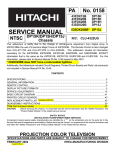
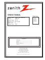
SERVICE MANUAL
Product Type:
Chassis:
Manual Series:
Manual Part #:
Model Line:
Product Year:
Model Series:
Digital Rear Projection
ZP26/28
PV154
923-03506
E
2002
CONTENTS
General Info ................................................. 1
Service Menu ................................................ 2
Servicing ..................................................... 3
Part List ...................................................... 4
Diagrams / PCB Layouts .................................. 5
Schematics ................................................... 6
Published August 2002
by Technical Publications
Zenith Electronics Corporation
201 James Record Road
Huntsville, Alabama 35824-1513
Copyright
Printed in U.S.A.
2002 by Zenith Electronics Corporation
R50V26
R56W28
R60V26
R65W28
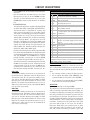
PRODUCT SAFETY SERVICING GUIDELINES FOR AUDIO-VIDEO PRODUCTS
IMPORTANT SAFETY NOTICE
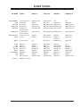
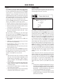
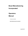
A.C. Voltmeter
This manual was prepared for use only by properly trained audio-video service
technicians.
When servicing this product, under no circumstances should the original
design be modified or altered without permission from Zenith Electronics
Corporation. All components should be replaced only with types identical to
those in the original circuit and their physical location, wiring and lead dress
must conform to original layout upon completion of repairs.
Special components are also used to prevent x-radiation, shock and fire hazard.
These components are indicated by the letter “x” included in their component
designators and are required to maintain safe performance. No deviations are
allowed without prior approval by Zenith Electronics Corporation.
0.15uF
Good Earth Ground
such as the Water
Pipe, Conduit, etc.
Circuit diagrams may occasionally differ from the actual circuit used. This way,
implementation of the latest safety and performance improvement changes into
the set is not delayed until the new service literature is printed.
1500 OHM
Place this probe
on each exposed
metal part.
10 WATT
X-RADIATION
CAUTION: Do not attempt to modify this product in any way. Never perform
customized installations without manufacturer’s approval. Unauthorized
modifications will not only void the warranty, but may lead to property damage
or user injury.
1.
Be sure procedures and instructions to all service personnel cover the
subject of x-radiation. The only potential source of x-rays in current TV
receivers is the picture tube. However, this tube does not emit x-rays when
the HV is at the factory-specified level. The proper value is given in the
applicable schematic. Operation at higher voltages may cause a failure of
the picture tube or high-voltage supply and, under certain circumstances
may produce radiation in excess of desirable levels.
2.
Only factory-specified CRT anode connectors must be used.
3.
It is essential that the service personnel have available an accurate and
reliable high-voltage meter.
4.
When the high-voltage circuitry is operating properly, there is no possibility
of an x-radiation problem. Every time a chassis is serviced, the brightness
should be run up and down while monitoring the high voltage with a
meter, to be certain that the high voltage does not exceed the specified
value and that it is regulating correctly.
5.
When troubleshooting and making test measurements in a product with a
problem of excessively high voltage, avoid being unnecessarily close to
the picture tube and the high voltage power supply. Do not operate the
product longer than necessary to locate the cause of excessive voltage.
6.
Refer to HV, B+, and shutdown adjustment procedures described in the
appropriate schematics and diagrams (where used).
Service work should be performed only after you are thoroughly familiar with
these safety checks and servicing guidelines.
GRAPHIC SYMBOLS
The exclamation point within an equilateral triangle is intended
to alert the service personnel to important safety information in
the service literature.
The lightning flash with arrowhead symbol within an equilateral
triangle is intended to alert the service personnel to the presence
of noninsulated “dangerous voltage” that may be of sufficient
magnitude to constitute a risk of electric shock.
The pictorial representation of a fuse and its rating within an
equilateral triangle is intended to convey to the service personnel
the following fuse replacement caution notice:
CAUTION: FOR CONTINUED PROTECTION AGAINST RISK OF FIRE,
REPLACE ALL FUSES WITH THE SAME TYPE AND RATING AS MARKED
NEAR EACH FUSE.
SERVICE INFORMATION
IMPLOSION
While servicing, use an isolation transformer for protection from AC line shock.
After the original service problem has been corrected, make a check of the
following:
FIRE AND SHOCK HAZARD
1. Be sure that all components are positioned to avoid a possibility of
adjacent component shorts. This is especially important on items transported to and from the repair shop.
1.
All direct view picture tubes are equipped with an integral implosion
protection system; take care to avoid damage during installation.
2.
Use only the recommended factory replacement tubes.
TIPS ON PROPER INSTALLATION
1.
Never install any receiver in a closed-in recess, cubbyhole, or closely
fitting shelf space over, or close to, a heat duct, or in the path of heated
air flow.
2.
Avoid conditions of high humidity such as: outdoor patio installations
where dew is a factor, near steam radiators where steam leakage is a factor,
etc.
3. Soldering must be inspected to discover possible cold solder joints, solder
splashes, or sharp solder points. Be certain to remove all loose foreign
particles.
3.
Avoid placement where draperies may obstruct venting. The customer
should also avoid the use of decorative scarves or other coverings that
might obstruct ventilation.
4. Check for physical evidence of damage or deterioration to parts and components, for frayed leads or damaged insulation (including the AC cord), and
replace if necessary.
4.
Wall- and shelf-mounted installations using a commercial mounting kit
must follow the factory-approved mounting instructions. A product mounted
to a shelf or platform must retain its original feet (or the equivalent
thickness in spacers) to provide adequate air flow across the bottom. Bolts
or screws used for fasteners must not touch any parts or wiring. Perform
leakage tests on customized installations.
5.
Caution customers against mounting a product on a sloping shelf or in a
tilted position, unless the receiver is properly secured.
6.
A product on a roll-about cart should be stable in its mounting to the cart.
Caution the customer on the hazards of trying to roll a cart with small
casters across thresholds or deep pile carpets.
7.
Caution customers against using a cart or stand that has not been listed
by Underwriters Laboratories, Inc. for use with its specific model of
television receiver or generically approved for use with TVs of the same or
larger screen size.
8.
Caution customers against using extension cords. Explain that a forest of
extensions, sprouting from a single outlet, can lead to disastrous
consequences to home and family.
2. Verify that all protective devices such as insulators, barriers, covers,
shields, strain reliefs, power supply cords, and other hardware have been
reinstalled per the original design. Be sure that the safety purpose of the
polarized line plug has not been defeated.
5. No lead or component should touch a high current device or a resistor
rated at 1 watt or more. Lead tension around protruding metal surfaces
must be avoided.
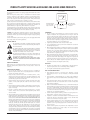
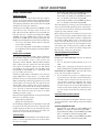
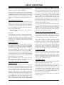
6. After reassembly of the set, always perform an AC leakage test on all exposed
metallic parts of the cabinet (the channel selector knobs, antenna terminals,
handle and screws) to be sure that set is safe to operate without danger of
electrical shock. DO NOT USE A LINE ISOLATION TRANSFORMER DURING THIS
TEST. Use an AC voltmeter having 5000 ohms per volt or more sensitivity in
the following manner: Connect a 1500 ohm, 10 watt resistor, paralleled by
a .15 mfd 150V AC type capacitor between a known good earth ground
water pipe, conduit, etc.) and the exposed metallic parts, one at a time.
Measure the AC voltage across the combination of 1500 ohm resistor and
.15 mfd capacitor. Reverse the AC plug by using a non-polarized adaptor
and repeat AC voltage measurements for each exposed metallic part. Voltage
measured must not exceed 0.75 volts RMS. This corresponds to 0.5 milliamp
AC. Any value exceeding this limit constitutes a potential shock hazard and
must be corrected immediately.
PV154 - 923-03506
i
ZP26/28 - SAFETY
PRODUCT SAFETY SERVICING GUIDELINES FOR AUDIO-VIDEO PRODUCTS
5. Do not use freon-propelled chemicals. These can generate electrical charge sufficient to damage ES devices.
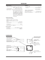
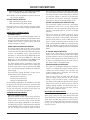
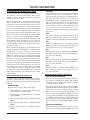
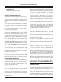
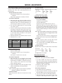
CRT ANODE HIGH VOLTAGE MEASUREMENT PROCEDURE
To prevent possible exposure to radiation caused by excessive CRT
Anode voltage, the High Voltage Shutdown circuit senses the level
of flyback pulse from “Flyback Transformer” representative of the
actual high voltage on the CRT anode. When this level exceeds a
predetermined voltage, the circuit shuts down the horizontal drive,
preventing further generation of anode voltage. In this condition,
the horizontal drive is “latched” off. The drive will remain off until
power (via remote control or front panel) is re-cycled from “Off” to
“On”.
6. Do not remove a replacement ES device from its protective package until immediately before you are ready to install t.(Most replacement ES devices are packaged with leads electrically shorted together by conductive foam, aluminum foil, or comparable conductive material.)
7. Immediately before removing the protective material from the
leads of a replacement ES device, touch the protective material to
the chassis or circuit assembly into which the device will be installed.
Critical Safety components (designated with an “X” in the component designator) are designed to operate the CRT at a safe operating
Anode voltage and provide proper shutdown thresholds . If replacement of any of these components are deemed necessary, it is important to use original type Zenith replacement components. After
replacement is made, confirm proper Anode voltage using the following procedure.
Caution: Be sure no power is applied to the chassis or circuit, and
observe all other safety precautions.
8. Minimize bodily motions when handling unpackaged replace ment
ES devices. (Otherwise, seemingly harmless motion, such as the brushing together of your clothing or the lifting of your foot from a
carpeted floor, can generate static electricity sufficient to damage
an ES device.)
Measurement of the CRT Anode voltage must be performed using a
high impedance high voltage meter, with no visible raster on the
screen, and operating at nominal horizontal scanning frequency.
Connect a strong broadcast signal (or TV signal generator operating
at 15.734kHz horizontal scanning rate) to the RF input.
REGULATORY INFORMATION
This equipment has been tested and found to comply with the limits
for a Class B digital device, pursuant to Part 15 of the FCC Rules.
These limits are designed to provide reasonable protection against
harmful interference when the equipment is operated in a residential
installation. This equipment generates, uses and can radiate radio
frequency energy and, if not installed and used in accordance with
the instruction manual, may cause harmful interference to radio
communications. However, there is no guarantee that interference
will not occur in a particular installation. If this equipment does
cause harmful interference to radio or television reception, which
can be determined by turning the equipment off and on, the user is
encouraged to try to correct the interference by one or more of the
following measures: Reorient or relocate the receiving antenna; Increase the separation between the equipment and receiver; Connect
the equipment into an outlet on a circuit different from that to
which the receiver is connected; Consult the dealer or an experienced radio/TV technician for help.
After discharging the CRT, connect a high impedance high voltage
meter to the CRT anode. Turn the television “on” and confirm a good
signal is being displayed . Reduce Brightness and Contrast settings
until the picture is well extinguished. If the voltage reading is
higher than the maximum, verify circuit component values and
proper operation.
B+ VDC
(0 BEAM)
115 +/- 2%
HV NOM
KV
30.2
HV MAX
KV
30.5
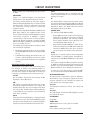
SHUTDOWN TEST PROCEDURE
Equipment needed is a video generator, HV DC meter (0 to 40 KV,
high Z), and a external variable power supply (0V to 6VDC @ 5Amps
minimum).
The presence of the DTV certification mark indicates that this product will successfully receive digital television transmissions that
conform to any and all of the video formats described in the ATSC
Digital Television Standard.
To verify the Shutdown Circuit is operating properly, Supply +6V DC
to pin 1 of P1407 and ground to Heat sink of Q1413. If there is no
raster and set goes into Shutdown, then the Shutdown Circuit is
functional. If the set doesn’t go into Shutdown, then the Circuit is
defective.
The responsible party for this device’s compliance is:
Zenith Electronics Corporation
201 James Record Road
Huntsville, AL 35824, USA
Digital TV Hotline: 1-800-243-0000
ELECTROSTATICALLY SENSITIVE DEVICES
Some semiconductor (solid-state) devices can be damaged easily by
static electricity. Such components commonly are called Electrostatically Sensitive (ES) Devices. Examples of typical ES devices are
integrated circuits and some field-effect transistors and semiconductor “chip” components. The following techniques should be
used to help reduce the incidence of component damage caused by
static electricity.
TRADEMARKS USED IN THIS MANUAL
Dolby Digital® Manufactured under license from Dolby Laboratories.
“Dolby” and the double-D symbol are trademarks of Dolby Laboratories. Confidential Unpublished Works. ©1992-1997 Dolby Laboratories, Inc. All rights reserved.
VCR Plus+, PlusCode and GUIDE Plus+ are trademarks of Gemstar
Development Corporation. The VCR Plus+ and GUIDE Plus+ systems
are manufactured under license from Gemstar Development Corporation and VCR Index Systems B.V., respectively.
Gemstar is not in any way liable for the accuracy of the program
schedule information provided by the GUIDE Plus+ system. In no
event shall Gemstar be liable for any amounts representing loss of
profits, loss of business, or indirect, special, or consequential damages in connection with the provision or use of any informaion,
equipment, or services relating to the GUIDE plus+ system.
SRS and the symbol are trademarks of SRS labs, Inc. SRS technology
is incorporated under license from SRS Labs, Inc.
Licensed by BBE Sound, Inc. under USP4638258 and 4482866. BBE
and the symbol are registered trademarks of BBE Sound, Inc.
1. Immediately before handling any semiconductor component or
semiconductor-equipped assembly, drain off any electrostatic charge
on the body by touching a known earth ground. Alternatively, obtain and wear a commercially available discharging wrist strap device, which should be removed for potential shock reasons prior to
applying power to the unit under test.
2. After removing an electrical assembly equipped with ES devices,
place the assembly on a conductive surface such as an ESD mat, to
prevent electrostatic charge buildup or exposure of the assembly.
3. Use only a grounded-tip soldering iron to solder or unsolder ES
devices.
4. Use only an anti-static solder removal device. Some solder removal devices not classified as “anti-static” can generate electrical
charges sufficient to damage ES devices.
PV154 - 923-03506
ii
ZP26/28 - SAFETY
PRODUCT SAFETY SERVICING GUIDELINES FOR AUDIO-VIDEO PRODUCTS
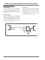
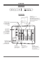
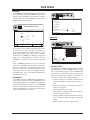
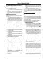
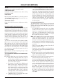
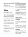
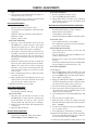
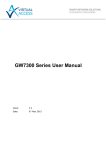
HOLD-DOWN CIRCUIT INFORMATION
NORMAL CONDITION
In normal condition, the DC voltage at point a is approximately 4.88V through pin 1 of P1407 (HV Block).
The voltage at point b is approximately 4.86V. The
voltage of pin 5 of IC404 is lower than the voltage of
pin 6 (5.1V). The voltage of pin 7 is 0V and the transistor Q403 is off.
ABNORMAL CONDITION
In abnormal condition, the voltage of point b is much
higher than normal voltage. The voltage of pin 5 of IC404
is 24V and the transistor Q403 is on. Therefore, pin 1 of
IC401 receives a voltage causing the hold-down circuit
to be active. This results in the frequency of the horizontal oscillation and deflection to be stopped and then
the set goes into stand-by mode.
X-RAY PROTECTION
Check the X-Ray protection circuit using the following
steps. Turn the set on and input a color bar signal. Check
the B+ voltage to make sure it is correct. If B+ is 148 to
160 VDC, the power circuit is defective. To check the
operation of the hold-down circuit, apply DC 6V (+- 0.5)
to point a . If there is no raster, the set is operating
properly and doesn’t need to be repaired.
P1407 (H.V. Block)
IC401
IC404
a
R1455
1
b
R493
5
R411
1
6
C1439
R1435
C417
HPROT
7
J8
ZD406
(5.1V)
Q403
R410
R491
C455
PV154 - 923-03506
- iii -
ZP26/28 - SAFETY
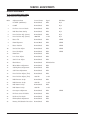
TABLE OF CONTENTS
SECTION 1 .................... OVERVIEW
SERVICE ADJUSTMENTS .................................. 3-16
ZP-25 CHASSIS ADJUSTMENT ORDER ............. 3-16
CHASSIS PRE-HEAT RUN ADJUSTMENTS .......... 3-17
CHASSIS CUT-OFF (SCREENS) ADJUSTMENT ..... 3-17
CHASSIS PRE-FOCUS ADJUSTMENT ................ 3-17
DCU CROSSHATCH PHASE ADJUSTMENT .......... 3-17
CHASSIS HORIZONTAL PHASE ....................... 3-17
CHASSIS TILT (RASTER INCLINATION) ............ 3-18
CHASSIS BEAM ALIGNMENT ADJUSTMENT ....... 3-18
CHASSIS RED/BLUE RASTER OFFSET .............. 3-18
VERTICAL SIZE ADJUSTMENT ....................... 3-19
HORIZONTAL SIZE ADJUSTMENT .................... 3-19
BEAM FORM ADJUSTMENT ........................... 3-19
LENS FOCUS ADJUSTMENT ........................... 3-20
STATIC FOCUS ADJUSTMENT ......................... 3-20
BLUE DE-FOCUS ADJUSTMENT ...................... 3-20
WHITE BALANCE AND SUB BRIGHTNESS .......... 3-20
CHASSIS HORIZONTAL PHASE (FINE) ............. 3-21
CHASSIS INTELLISENSE “PATTERN SET UP” ...... 3-21
DIGITAL CONVERGENCE ALIGNMENT ............... 3-22
SUB PICTURE AMPLITUDE ........................... 3-22
OVERVIEW ..................................................... 1-1
ON SCREEN DISPLAY ..................................... 1-3
REMOTE BUTTON DESCRIPTIONS ..................... 1-5
PROGRAMMING THE REMOTE .......................... 1-5
REMOTE BRAND CODES .................................. 1-6
REMOTE CODES ............................................ 1-7
OPERATING MODE KEY FUNCTIONS ................... 1-8
USER MENUS .................................................. 1-9
USER MENUS ............................................ 1-10
SETUP ..................................................... 1-10
SPECIAL .................................................. 1-11
VIDEO MENU ............................................. 1-15
AUDIO MENU ............................................ 1-16
THEATER MENU ......................................... 1-17
POP-3 ..................................................... 1-17
SPLIT SCREEN ........................................... 1-17
SECTION 2 .............. SERVICE MENU
<PENDING>
SECTION 3 ....................SERVICING
SECTION 4 ........................... PARTS
CIRCUIT DESCRIPTIONS .................................... 3-1
POWER ON AND OFF ..................................... 3-1
POWER SUPPLY SHUTDOWN ........................... 3-1
STAND-BY MODE .......................................... 3-1
HOT SHUT DOWN SENSING CIRCUITS ................ 3-1
COLD SHUT DOWN SENSING CIRCUITS .............. 3-1
POWER SUPPLY SHUTDOWN CIRCUIT ................ 3-2
SHUTDOWN DETECTION CIRCUITS .................... 3-2
DEFLECTION SHUT DOWN CIRCUITS ................. 3-2
SHUT DOWN CIRCUIT DESCRIPTIONS ................ 3-3
SUB POWER SUPPLY VISUAL LED .................... 3-5
VOLTAGE LOSS OR EXCESSIVE LOAD DETECTION .. 3-5
B+ VOLTAGE TOO HIGH ................................. 3-5
SHUT DOWN CIRCUIT .................................... 3-5
B+ GENERATION FOR SUB POWER SUPPLY ......... 3-6
DEFLECTION POWER SUPPLY VISUAL LEDS ........ 3-6
DEFLECTION POWER DRIVER B+ GENERATION ..... 3-6
DEFELCTION GENERAL INFORMATION ................ 3-7
MAIN MICROPROCESSOR .............................. 3-12
DAC1 I006 ............................................... 3-13
DAC3 I007 ............................................... 3-13
LEVEL SHIFT I004 ..................................... 3-13
3D Y/C I301 ............................................. 3-13
MAIN VIDEO CHROMA I501 (PREPARATION IC) 3-14
RAINFOREST IC01 (VIDEO/CHROMA PROCESSOR)3-14
A/V SELECTOR IX01 ................................... 3-14
SUB VIDEO CHROMA IX03 ........................... 3-14
MAIN Y PR/PB SELECTOR IX04 ..................... 3-14
SUB Y PR/PB SELECTOR IX04 ....................... 3-14
FRONT AUDIO CONTROL IC IA01 ................... 3-14
SRS AUDIO ............................................... 3-15
PV154 - 923-03506
MODEL PARTS ............................................. 4-1
SECTION 5 .................... DIAGRAMS
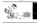
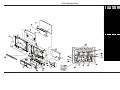
ZP26/28 EXPLODED VIEW ................................. 5-1
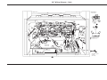
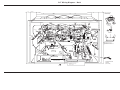
50” WIRING DIAGRAM - BACK ........................... 5-2
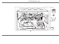
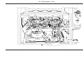
60” WIRING DIAGRAM - BACK ........................... 5-3
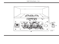
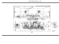
50/60” WIRING DIAGRAM - FRONT ..................... 5-4
56” WIRING DIAGRAM - BACK ........................... 5-5
65” WIRING DIAGRAM - BACK ........................... 5-6
56/65” WIRING DIAGRAM - FRONT ..................... 5-7
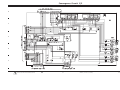
ZP26/28 SRS PWB .......................................... 5-8
SECTION 6 .................. SCHEMATICS
CONVERGENCE CIRCUIT 1/2 ............................... 6-1
CONVERGENCE CIRCUIT 2/2 ............................... 6-2
MAGIC FOCUS CIRCUIT ..................................... 6-3
DEFLECTION POWER SUPPLY CIRCUIT .................. 6-4
DEFLECTION CIRCUIT ....................................... 6-5
POWER SUPPLY CIRCUIT ................................... 6-6
SIGNAL CIRCUIT 1/4 ....................................... 6-7
SIGNAL CIRCUIT 2/4 ....................................... 6-8
SIGNAL CIRCUIT 3/4 ....................................... 6-9
SIGNAL CIRCUIT 4/4 ..................................... 6-10
SRS CIRCUIT ................................................ 6-11
VELOCITY MODULATOR CIRCUIT ........................ 6-12
TOC-1
ZP26/28 - TOC
SECTION 1
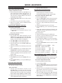
OVERVIEW
OVERVIEW
R56W28 & R65W28
R50V26 & R60V26
The R56/65W28 and R50/60V26 are HDTV Monitors. This means that most of the components of a HDTV are present
except for the ASTC tuner. An HDTV receiver or converter box is required to view an ASTC signal. The W28 models feature
a 16:9 aspect ratio screen. But, it can display video in several different aspect ratios, including 16:9 and 4:3. More
features and specifications are listed below.
Currently the ZP-26/28 chassis is module level repair only. Schematics and PCB layouts are provided to assist in
troubleshooting. Follow the normal procedures required for module level repair.
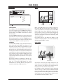
FEATURES
IMPROVED-HD DRIVER
Most HDTVs use upconversion of analog signals (linedoubling) to simulate an HD picture, which introduces
artifacts that appear as pixilated scenes due to digital
conversion. Improved-HD dramatically improves this
process and produces images free rom picture artifacts
by increasing both vertical and horizontal resolution. True
HD signals are not affected by this process, leaving them
as true to life as possible.
ENHANCED HD LENS SYSTEM
New 4 Element enhanced lens system improves brightness
and focus over the previous 25 series and provides a
more natural looking and true-to-life picture.
HD FOCUS (W28 MODELS)
Automatic system that eliminates the need to manually
adjust the picture. Simply select HD focus from the
onscreen set-up menu, and in approximately 8-10
seconds, over 8,000 points on the screen are adjusted,
for perfect center to edge focus of the image.
IMPROVED PICTURE
Zenith’s 26 and 28 series projection televisions feature a
.52mm screen pitch, improved image scaling, and new 7"
CRTs yielding sharper images and finer detail. This
represents significant improvement compared to our
previous 94/95/25 series. The screen also features a
scratch resistant coating.
DIGITAL FOCUS ARRAY (V26 MODELS)
New advanced convergence technology is more accurate
than previous digital convergence, and is set at the
factory by a computer. The 9-Point system actually looks
at 117 points, since it interpolates between points,
yielding an image that is sharp from center to edge.
PV154 - 923-03506
3:2 PULLDOWN DETECTION
Most movies are shot on film, and film operates at a frame
rate of 24fps (frames per second), compared to video
which operates at 30fps, 3:2 pulldown properly detects
and syncs film to video for smooth theater like pictures
at home.
1-1
ZP26/28 - OVERVIEW
OVERVIEW
REMOTE CONTROL
Transmitter Universal Remote w/Glow Channel & Volume
Model Number ....................................... MBR5045
R50/60V26 SPECIFICATIONS
VIDEO
Picture Tubes .......................................... 7" LFM
Resolution Display .......................... 540p or 1080i
Mirror ........................................ 1st Surface Glass
Lens System ..................................... Enhanced HD
Tuning System ....................... NTSC + Up Converter
Scan Velocity Modulation ................ Advanced SVM
Dynamic Focus ............................................... Yes
Digital Convergence ....................... 9-Point Digital
Color Temperature .......................... Cool/Warm/STD
Comb Filter .................................... Digital 3D Y/C
Horizontal Lines Resolution .......................... 1200
Picture In Picture (PIP) ........................... 2 Tuner
Advanced features .. Light Sentry, Detail Enhance, Super Contrast, Gamma Correction, Auto Flesh Tone, Wide
Band Video Amp
APPROVALS
UL, C-UL, NOM ....................................... UL, C-UL
UPC Code ............................. 50”:04464200642 6
60”:04464200632 7
SERVICE/LIMITED WARRANTY
Service Support Level .................. “M” Module Level
Warranty: Parts/CRT/Labor ...... 1 Year/2 Years/1 Year
R56/65W28 SPECIFICATIONS
VIDEO
Picture Tubes .......................................... 7" LFM
Resolution Display .......................... 540p or 1080i
Mirror ........................................ 1st Surface Glass
Lens System ..................................... Enhanced HD
Tuning System ....................... NTSC + Up Converter
Lens Elements .................................................. 4
Lens Filters ...................... Red & Green Color Purity
Screen w/Surface Diffuser ........ 160° Viewing Angle
Scan Velocity Modulation ................ Advanced SVM
Dynamic Focus ............................................... Yes
Digital Convergence ....................... 9-Point Digital
Picture In Picture (PIP) .................................. Yes
Picture Outside Picture (POP) .......... 3/Split Screen
Color Temperature .......................... Cool/Warm/STD
Black Level Exp./White Level Compression NTSC Fixed
Home Theater Mode TV, Movie, Sports, Music, Reset
Comb Filter .................................... Digital 3D Y/C
Horizontal Lines Resolution .......................... 1200
Picture In Picture (PIP) ........................... 2 Tuner
Aspect Ratio .......... Normal, Wide, Panoramic, Zoom
Advanced features .. Light Sentry, Detail Enhance, Super Contrast, Gamma Correction, Auto Flesh Tone,
Wide Band Video Amp
AUDIO
Front Surround (SRS) ...................................... Yes
Mono/Stereo/MTS/SAP ............................ MTS/SAP
Bass/Treble/Balance (Tone Control) ................... Yes
Total Audio (Watts) ....................... 24W (2 x 12W)
Auto Noise Cancel .......................................... Yes
Audio Boost ......................................... Loudness
SPECIAL FEATURES
HD Monitor ................................... Digital Display
Displays Digital Signals at 540p
or 1080i (User Selects)
Tri-lingual Menus ............. English, Spanish, French
Other features .. Icon Menus, Source ID, Channel Labels, Parental Control with VChip, On/Off Timer, Flashback, CC,
CC When Mute, 2 Level Mute,
Channel Review, Channel Skip,
Power Resume, On/Off Speaker Selection, Date/Time/Channel
CABINET
Dimensions and weight:
R50V26: 43.5"w x 52"h x 23.5"d @177Lbs
R60V26: 51.5"w x 60.5"h x 26.5"d @226Lbs
Finish ............................................... Light Silver
Screen Protector ............................. High Contrast
Swivel/Casters .......................................... Casters
Control Panel Escut. (Buttons) ........................... 8
PV154 - 923-03506
AUDIO
Front Surround (SRS) ...................................... Yes
Mono/Stereo/MTS/SAP ............................ MTS/SAP
Bass/Treble/Balance (Tone Control) ................... Yes
Total Audio (Watts) ....................... 24W (2 x 12W)
Auto Noise Cancel .......................................... Yes
Audio Boost ......................................... Loudness
1-2
ZP26/28 - OVERVIEW
OVERVIEW
SPECIAL FEATURES
HD Monitor Digital DisplayDisplays Digital Signals at
540p or 1080i (User Selects)
Tri-lingual Menus ............ English, Spanish, French
Other features .. Icon Menus, Source ID, Channel Labels, Parental Control with VChip, On/Off Timer, Flashback,
CC, CC When Mute, 2 Level Mute,
Channel Review, Channel Skip,
Power Resume, On/Off Speaker
Selection, Date/Time/Channel,
Energy Star®
APPROVALS
UL, C-UL, NOM ....................................... UL, C-UL
UPC Code ............................ 56”:04464200622 8
65”:04464200612 9
SERVICE/LIMITED WARRANTY
Service Support Level ..................... “M” Module Level
Warranty: Parts/CRT/Labor ......... 1 Year/2 Years/1 Year
CABINET DESCRIPTION
Dimensions and weight:
R56W28: 54.1"W x 52.21"H x 24.2"D
R65W28: 60.01"W x 62.01"H x 26.3"D
Finish ............................................... Light Silver
Screen Protector ............................. High Contrast
Swivel/Casters .......................................... Casters
Control Panel Escut. (Buttons) ........................... 8
REMOTE CONTROL
Transmitter ..................... Universal Remote w/Glow
Model Number ....................................... MBR5045
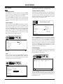
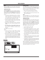
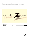
ON SCREEN DISPLAY
MAIN PICTURE SOURCE
RATING BROADCAST
Displays Main Picture Source
Active source highlighted).
Displays the rating for the program
currently being broadcast.
AUDIO SELECTED
Displays signal’s audio setting.
STEREO
ST / SAP
ANT 1 110
ABC
10 : 00 AM
May 14 2002
TV - PG DLSV
AUDIO BROADCAST
Displays signal’s audio broadcast.
CHANNEL LABEL
Displays channel label you
have chosen.
TIME
Displays clock setting.
MONTH/DATE/YEAR
Shows current month, date,
and year.
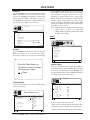
CHANNEL SKIP
STEREO
ST / SAP
TV - PG DLSV
Shows that Channel Skip is active.
SECURITY TIMER
Displays time that TV is set to
turn off.
SLEEP TIMER SET
Displays time left on Sleep Timer
before TV shut off.
ANT 1 110
ABC
10 : 00 AM
PIP ANT 1
14
C. SKIP ( C. S. )
SKIP ( C. S. )
OFF 10:05 AM
OFF 10:05 AM
SLEEP
SLEEP
0:01
TV
Normal
0:01
PICTURE FORMAT
TV
Normal
PV154 - 923-03506
1-3
Shows current Theater mode
setting.
ZP26/28 - OVERVIEW
OVERVIEW
FRONT CONNECTIONS
menu source
select
- volume +
- channel +
power
S-Video Video L/Mono R
exit
REAR CONNECTIONS
Inputs 3 and 4
Y, PB, PR, and Audio L - R
Component Video
Some top-of-the-line DVD players use
what is called “component video,” for
extremely accurate picture reproduction.
Refer to your DVD manual for
further information.
S-Video Input 1 and 2
Connections available
for some high-end
equipment that provides
even better picture
quality.
ANTENNA/
CABLE 1
RF Connectors:
Antenna/Cable 1,
Antenna/Cable 2,
and Cable Box
Used to connect cable
service to the television,
either directly or
through your cable box.
INPUT 1 INPUT 2
TO CABLE
BOX
VARIABLE
AUDIO OUT
R
L
MONITOR
OUT
INPUT 4
S-VIDEO S-VIDEO
VIDEO
ANTENNA/
CABLE 2
INPUT 3
S-VIDEO
VIDEO Y/VIDEO
VIDEO
Y/VIDEO
MONO/L
MONO/L
PB
MONO/L
PB
MONO/L
L
R
R
PR
R
PR
R
R
AUDIO
AUDIO
AUDIO
AUDIO
AUDIO
Variable Audio Out
Used to connect
either an external
amplifier or add a
sub-woofer to your
surround sound system.
Video 1 or 2
Connects the video
signals from various
types of equipment.
PV154 - 923-03506
Right/Left Audio
Used for stereo sound
from various types of
equipment.
1-4
Monitor Out
These jacks provide fixed
audio and video signals
which are used for recording.
Use S-Video Output
for high quality video output.
ZP26/28 - OVERVIEW
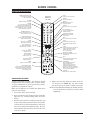
REMOTE CONTROL
REMOTE BUTTON DESCRIPTIONS
MODE INDICATOR LIGHTS
Light indicates mode when
keys are pressed.
Part Number
MBR6045A
924-10098
SOURCE
Selects available TV sources.
MODES
TV, VCR, Cable, DVD, HD/STB
Switches remote operating mode
to control other devices. After pressing
a Mode switch key, wait 2 - 3 seconds
before pressing any other key.
NUMBER KEYPAD 0 - 9
Selects channels directly and
enters numerical values.
vcr cable dvd hd/stb
tv
source
mode
tv
vcr
cable
dvd
hd/stb
aspect
2
3
1
DIGITAL MODE DASH
Use as the dash when selecting
digital channel numbers.
4
5
6
7
8
9
0
display
MUTE
Press once for Soft Mute,
press again for full Mute.
VOL - (VOLUME) (+/-)
+ Increases the sound level.
- Decreases the sound level.
SPLIT
Turns the “Split Screen”
feature on and off.
SLEEP (TIMER)
Sets a preset time
for the TV to turn off.
power
light
mute
flshbk
vol
ch
split
multi
pip ch
sleep
CC
fav ch quit
c skip
menu
VCR FUNCTION KEYS
Record, Stop, Pause, REW (Rewind),
Play, FF (Fast Forward). These buttons
still operate the VCR while remote is
in TV operating mode.
POWER
Turns TV On and Off.
ASPECT
Selects different picture
proportion formats.
DISPLAY
Shows current on-screen settings.
CH - CHANNEL (+/ -)
Tunes to next higher/lower
available channel.
FLSHBK (FLASHBACK)
Returns to the previously
tuned channel.
MULTI
Turns “POP-3” feature on and off.
PIP CH
Channel tuning switch in Split
Screen mode. See Split Screen
section.
C SKIP
Channel Skip. Tunes to last channel
viewed. Tunes back to original
channel after 30, 60, 90, 120,
150, or 180 seconds.
FAVORITE CHANNEL
Select among 6 different channel
classifications.
QUIT
Leaves programming menus and
clears screen of displays
CC
Turns On/Off Closed
caption/text options.
MENU
Displays on-screen menus.
LIGHT
Lights keys for five seconds.
theatr
record stop
pause rew
skip
play
ff
THUMBSTICK
(Menu Operation Directional
Arrows and Select key)
Up/Down arrows choose, and
Left/Right arrows adjust menu
options. Press the bulls eye Select
button in the center of the directional
arrows to confirm selection.
THEATER
Direct access to theater modes.
PROGRAMMING THE REMOTE
If you’re using Zenith products, the remote is already
programmed for most common codes. For other brands,
or if your remote fails to control your Zenith products,
you’ll have to program the remote.
Make sure the batteries are installed and follow these
steps for each product:
1. Turn on the device to be operated.
2. Press and hold the device button until the indicator
light turns on, continue holding down the device
button.
3. Now the remote control is ready to program the code
for the corresponding component. Enter the product’s
code number using the number buttons. Code numbers can be found on the following pages. The indicator light will flash three times and turn off if the
code was accepted.
PV154 - 923-03506
4. Release the mode key. Point the remote at the device and press the POWER key. The device should
turn off. If not, try the other 3-number codes listed.
NOTE: Use the CABLE device button for satellite receivers.
Use the DVD device button for home audio
components.
1-5
ZP26/28 - REMOTES
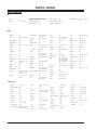
REMOTE CONTROL
REMOTE BRAND CODES
TVs
Daewoo . . . . . . . 149
TV/VCR Combination Codes
Funai TV/VCR. . . . 154
Zenith . . . . . . . . 101 121 149 152
Adventura TV/VCR . 154
Goldstar TV/VCR . . 153 172
Daewoo TV/VCR . . 148
Symphonic TV/VCR 154
Zenith TV/VCR . . . 150 152 153 154
172
VCRs
Admiral . . . . . . . 261
Akai . . . . . . . . . . 292 717 718 719
720
General Electric . . 216 220 266 282
701 702 725
Orion . . . . . . . . . 250
Sears . . . . . . . . . 211 212 213 265
274
Go Video . . . . . . . 256 262 263 700
Panasonic . . . . . . 245 251 259 713
714 715 716
Audio Dynamics . . 726
Goldstar . . . . . . . 253
Pentax . . . . . . . . 708 727
Signature 2000 . . . 216 219 249
Bell & Howell . . . . 247
Harmon Kardon . . . 296
Philco . . . . . . . . . 275
Sony . . . . . . . . . 232 723 724
Broksonic . . . . . . 221 250 255 729
Hitachi . . . . . . . . 257 270 273 292
705 706 707 708
Pioneer . . . . . . . 210 282 726
Sylvania . . . . . . . 275 297
Portland . . . . . . . 246 727
Tatung . . . . . . . . 268 292
ProScan . . . . . . . 216 260 266 282
725
Teac . . . . . . . . . . 268
Candle . . . . . . . . 727
Canon . . . . . . . . . 704
Capeheart . . . . . . 728
Citizen . . . . . . . . 727
Craig . . . . . . . . . 212
J.C. Penny . . . . . . 268 726
Jensen . . . . . . . . 292
JVC . . . . . . . . . . 224 225 258 268
292 299 726
Kenwood . . . . . . . 268 292 726 727
MGA . . . . . . . . . . 297 730
Realistic . . . . . . . 212 213 265 730
Yamaha . . . . . . . . 726
Mitsubishi . . . . . . 276 277 278 279
280 296 297 730
Saisho. . . . . . . . . 722
Zenith . . . . . . . . 201 224 225 229
Montgomery Ward
Samsung . . . . . . . 220 230
Daewoo . . . . . . . 244 246 248 254
703 729
Marantz . . . . . . . 267 268 726 727
Electrochrome. . . . 730
Emerson . . . . . . . 203 221 243 250
293 721 722 729
730 731 732
Fisher . . . . . . . . . 211 212 213 247
265 274
216 219 249 291
730
228
260
284
288
725
Vector Research . . 726 727
Memorex . . . . . . . 212 298
Magnavox . . . . . . 275
DBX . . . . . . . . . . 726
Toshiba . . . . . . . . 213 274 290 297
Radio Shack . . . . . 213 265 730
220
249
283
287
711
Teknika . . . . . . . . 272
RCA . . . . . . . . . . 216
242
282
286
710
Curtis Mathes . . . 259 266 725 727
Daytron . . . . . . . 246
Quasar . . . . . . . . 259 295
Sharp . . . . . . . . . 261 730
240
266
285
708
Victor . . . . . . . . . 726
Video Concepts . . . 726 727
XR - 1000 . . . . . . 243
Salora . . . . . . . . . 297
Sansui . . . . . . . . 289 292 709 726
MultiTech. . . . . . . 727
NEC . . . . . . . . . . 267 268 269 281
292 709 726
Sanyo . . . . . . . . 212 247 294
Scott . . . . . . . . . 243 290 729
Cable Boxes
Allegro . . . . . . . . 358 362
Allegro A-B Switch 361
Archer . . . . . . . . 325
Hamlin . . . . . . . . 302 303 345 365
366
Jasco . . . . . . . . . 325
352 354 355
Teleview . . . . . . . 326
Pioneer . . . . . . . . 315 343
Texscan . . . . . . . 339 356 371
RCA . . . . . . . . . . 341
Tocom . . . . . . . . 317 318 346
Century . . . . . . . . 325
Jerrold . . . . . . . . 304 307 308 309
310 318 360 363
Regency . . . . . . . 329
Unika . . . . . . . . . 325 348 362
Citizen . . . . . . . . 325
Kale Vision . . . . . 335
Samsung . . . . . . . 326 335
Universal . . . . . . 325 358 362
Comtronic . . . . . . 326
Macom . . . . . . . . 321
Scientific Atlanta
Vid Tech . . . . . . . 340
Everquest. . . . . . . 379
Magnavox . . . . . . 327 334
Garrard . . . . . . . . 325
316 323 336 337
364
Signal . . . . . . . . . 326
Gemini . . . . . . . . 305 331 338
NSC . . . . . . . . . . 335 339 368 369
370
SL Marx . . . . . . . . 326
General Electric. . . 367
Oak . . . . . . . . . . 311 332 342
Sprucer . . . . . . . . 313
General Instrument 304 305 306 307
308 309 310 318
Panasonic . . . . . . 313 320
Standard Comp . . . 335
Philips . . . . . . . . 325 327 347 350
Stargate . . . . . . . 326 379
923-03460
1-6
Video Way . . . . . . 349
Viewstar . . . . . . . 327 354 355 372
Zenith HT-2000. . . 353
Zenith PM . . . . . . 374
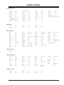
ZP26/28 - REMOTES
REMOTE CODES
REMOTE CONTROL
Satellite Receivers
Alphastar. . . . . . . 516
Hughes Network . . 514
RCA . . . . . . . . . . 510 517
Toshiba . . . . . . . . 509 512
Chaparral . . . . . . . 501 502
JVC . . . . . . . . . . 518
Realistic . . . . . . . 506
Uniden . . . . . . . . 522
Cheyenne. . . . . . . 502
Macom . . . . . . . . 314
Sierra I . . . . . . . . 502
United . . . . . . . . 344
Dishnet . . . . . . . . 515
Magnavox . . . . . . 521
Sierra II . . . . . . . 502
Zenith Drake. . . . . 312 330
Drake . . . . . . . . . 503
Phillips . . . . . . . . 521
Sierra III . . . . . . . 502
Zenith Satellite . . 328 351 378 500
General Electric. . . 510 517
PrimeStar. . . . . . . 513
Sony. . . . . . . . . . 511
General Instrument 504 505
ProScan. . . . . . . . 510 517
STS1 . . . . . . . . . . 507
Hitachi . . . . . . . . 519 520
RCA DSS . . . . . . . 373
STS3 . . . . . . . . . . 508
JVC . . . . . . . . . . 965
Pioneer . . . . . . . . 963
Toshiba . . . . . . . . 961
Mitsubushi . . . . . . 964
Sony. . . . . . . . . . 962
Zenith. . . . . . . . . 960
DVD Players
Audio CD Players
ADC . . . . . . . . . . 940
JVC . . . . . . . . . . 949 954
Phillips . . . . . . . . 421 433 434
Soundesign . . . . . 461 498 901 902
ADO . . . . . . . . . . 939
Kenwood . . . . . . 441 931 948
Pioneer . . . . . . . . 431 435 944
Sylvania . . . . . . . 433
Aiwa. . . . . . . . . . 938
Luxman . . . . . . . . 930
Quasar . . . . . . . . 432
Teac . . . . . . . . . 418 419
Akai . . . . . . . . . . 937
Magnavox . . . . . . 421 422 433 434
Radio Shack . . . . . 431 441
Technics . . . . . . . 432
Denon . . . . . . . . 935
Marantz . . . . . . . . 929 947
RCA . . . . . . . . . . 437 943
Toshiba . . . . . . . . 915
Dynatech . . . . . . . 953
MCS . . . . . . . . . . 928
Sanyo . . . . . . . . . 438 439
Yahama . . . . . . . . 414 941 942
Emerson . . . . . . . 952
Mitsubishi . . . . . . 927
Sears . . . . . . . . . 936
Fisher . . . . . . . . . 438 933 951
Nakamichi . . . . . . 925 926
Sharp . . . . . . . . . 441 442
Zenith . . . . . . . . 460 461 498 901
902
GE . . . . . . . . . . . 932
Onkyo . . . . . . . . 923 924 946
Sherwood . . . . . . 449
Goldstar . . . . . . . 460
Optimus . . . . . . . 920 921 922
Hitachi . . . . . . . . 950
Panasonic . . . . . . 431 432 945
Sony. . . . . . . . . . 420 443 444 445
934
Zenith CD Recorder 415
Audio Tape Decks
Sony. . . . . . . . . . 452
Audio Tuners/Amps
Citizen . . . . . . . . 914
Marantz . . . . . . . . 903 913
Pioneer . . . . . . . . 470 485 907
GE . . . . . . . . . . . 916
Memorex . . . . . . . 485
Proton . . . . . . . . 910
Goldstar . . . . . . . 460 474
Nad . . . . . . . . . . 904
Quasar . . . . . . . . 912
Hitachi . . . . . . . . 919
Nakamichi . . . . . . 493
RCA . . . . . . . . . . 909
JVC . . . . . . . . . . 908
Onkyo . . . . . . . . 471 906
Sharp . . . . . . . . . 483 917 918
Kenwood . . . . . . . 484
Optimus . . . . . . . 905
Sherwood . . . . . . 900
Luxman . . . . . . . . 467
Panasonic . . . . . . 912
Sony. . . . . . . . . . 486 489 490
491 492
Soundesign . . . . . 461 498 901
902
Techniques. . . . . . 912
Toshiba . . . . . . . . 915
Victor . . . . . . . . . 908
Zenith . . . . . . . . 460 461 498
901 902
HD/Set Top Boxes
Echostar . . . . . . . 805
Philips . . . . . . . . 802
Sony. . . . . . . . . . 801
Hughes . . . . . . . . 803
RCA . . . . . . . . . . 804
Zenith. . . . . . . . . 800
PV154 - 923-03506
1-7
ZP26/28 - REMOTES
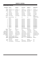
REMOTE CONTROL
OPERATING MODE KEY FUNCTIONS
KEY NAME
source
light
power
tv
vcr
cable
dvd
hd/stb
aspect
1
2
3
4
5
6
7
8
9
0
display
mute
volume (up)
volume (down)
channel (up)
channel (down)
flashbk
split
multi
pip ch
c skip
sleep
cc
923-03460
TV Mode
VCR Mode
Cable Mode
DVD Mode
HD/STB Mode
TV Sources
Lights Keys 5 Seconds
TV On/Off
Selects TV
Selects VCR
Selects Cable
Selects DVD
Selects HD/STB
TV Sources
Lights Keys 5 Sec
VCR On/Off
Selects TV
Selects VCR
Selects Cable
Selects DVD
Selects HD/STB
TV Sources
Lights Keys 5 Sec
Cable Box On/Off
Selects TV
Selects VCR
Selects Cable
Selects DVD
Selects HD/STB
TV Sources
Lights Keys 5 Sec
DVD On/Off
Selects TV
Selects VCR
Selects Cable
Selects DVD
Selects HD/STB
Selects Aspect Ratio
Formats
TV Digit 1
TV Digit 2
TV Digit 3
TV Digit 4
TV Digit 5
TV Digit 6
TV Digit 7
TV Digit 8
TV Digit 9
TV Digit 0
N/A
TV Display
TV Mute
TV Volume Up
TV Volume Down
TV Channel Up
TV Channel Down
TV Flashback
TV Split Screen On/Off
TV POP-3 Multi On/Off
TV Split Screen Channel
Tuning Switch
Channel Skip
TV Sleep Timer
TV Closed Captions
N/A
N/A
N/A
VCR Digit 1
VCR Digit 2
VCR Digit 3
VCR Digit 4
VCR Digit 5
VCR Digit 6
VCR Digit 7
VCR Digit 8
VCR Digit 9
VCR Digit 0
N/A
VCR Memory
TV Mute
TV Volume Up
TV Volume Down
VCR Channel Up
VCR Channel Down
TV Flashback
VCR+
VCR Search
VCR Display
Cable Digit 1
Cable Digit 2
Cable Digit 3
Cable Digit 4
Cable Digit 5
Cable Digit 6
Cable Digit 7
Cable Digit 8
Cable Digit 9
Cable Digit 0
Cable/Satellite Dash
N/A
TV Mute
TV Volume Up
TV Volume Down
Cable Channel Up
Cable Channel Down
Cable Flashback
Cable/Sat Day Up
Cable/Sat Day Down
N/A
DVD Digit 1
DVD Digit 2
DVD Digit 3
DVD Digit 4
DVD Digit 5
DVD Digit 6
DVD Digit 7
DVD Digit 8
DVD Digit 9
DVD Digit 0
DVD Zoom
DVD Display
TV Mute/Sound
TV Volume Up
TV Volume Down
DVD Skip>>
DVD Skip <<
DVD Return
DVD Marker
DVD Repeat a-b
DVD Marker Search
TV Sources
Lights Keys 5 Sec
HD/STB On/Off
Selects TV
Selects VCR
Selects Cable
Selects DVD
Selects
HD/STB/direcTV
Selects Aspect Ratio
Formats
HD/STB Digit 1
HD/STB Digit 2
HD/STB Digit 3
HD/STB Digit 4
HD/STB Digit 5
HD/STB Digit 6
HD/STB Digit 7
HD/STB Digit 8
HD/STB Digit 9
HD/STB Digit 0
HD/STB Dash
N/A
TV Mute
TV Volume Up
TV Volume Down
HD/STB Channel Up
HD/STB Channel Down
HD/STB Flashback
N/A
N/A
STB Signal
VCR am/pm
VCR Timer
TV Closed Captions
N/A
Cable/Sat Timer
Cable/Sat Page Up
DVD Clear
DVD Repeat Chap
DVD Sub Title
N/A
N/A
N/A
1-8
ZP26/28 - REMOTES
USER MENUS
REMOTE CONTROL
KEY NAME
TV Mode
VCR Mode
Cable Mode
DVD Mode
HD/STB Mode
TV Favorite Channels
TV Menu Quit
TV Select Up
TV Select Down
TV Adjust Left
Favorite Channels
TV Adjust Right
Favorite Channels
TV Menu Item Select
TV Menu
VCR
VCR
VCR
VCR
VCR
Cable Page Down
Cable Quit
Cable/Sat Up Arrow
Cable/Sat Down Arrw
Cable/Sat Left Arrow
N/A
DVD
DVD
DVD
DVD
N/A
HD/STB
HD/STB
HD/STB
HD/STB
theater
record
stop
I<< skip
skip >>I
pause
rew (rewind)
play
ff
fav ch (Channel)
quit
up arrow
down arrow
left arrow
right arrow
Push “Select” ~
menu
Reference:
Channel Map
Quit
Select Up
Select Down
Tracking Down
Resume
Up Arrow
Down Arrow
Left Arrow
Quit
Up Arrow
Down arrow
Left arrow
VCR Tracking Up
Cable/Sat Right Arrw DVD Right Arrow
HD/STB Right arrow
VCR Enter
VCR Menu
Cable/Sat Enter
Cable/Sat Menu
HD/STB Enter
HD/STB Menu
TV Theater Modes
N/A
Cable/Sat Info
DVD Enter
DVD Menu
Disc Menu
DVD Open Close
VCR Record
VCR Stop
DVD Skip I<<
DVD Skip >>I
VCR Pause
VCR Rewind
VCR Play
VCR Fast Forward
VCR Record
VCR Stop
DVD Skip I<<
DVD Skip >>I
VCR Pause
VCR Rewind
VCR Play
VCR Fast Forward
Cable/Sat Buy
VCR Stop
DVD Skip I<<
DVD Skip >>I
Cable/Sat Guide
VCR Rewind
VCR Play
VCR Fast Forward
DVD
DVD
DVD
DVD
DVD
DVD
DVD
DVD
N/A
VCR Stop
DVD Skip I<<
DVD Skip >>I
HD/STB Guide
VCR Rewind
VCR Play
VCR Fast Forward
Angle
Stop/Eject
Skip I<<
Skip >>I
Pause
Scan <<
Play
Scan >>
HD/STB Info
MBR6045, 924-10098
PV154 - 923-03506
1-9
ZP26/28 - REMOTES
USER MENUS
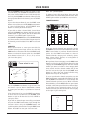
If certain CATV channels are not received clearly in
CATV1 mode, set the source to CATV2 mode.
USER MENUS
SETUP
CHANNEL ADD/DEL (DELETE)
Customize your channel selection list: Add Channels
not found by Scan (Channel Search), Delete channels
you don’t watch. Channels will appear when using
Channel Up/Down Press the MENU button on your
remote to access the Setup menu.
TRILINGUAL MENUS
Press MENU to access the Setup menu. Use the DOWN
arrow to choose Trilingual. Press the RIGHT arrow
button to activate the Language menu option.
Use the UP/DOWN arrow button to choose your language
preference for the on-screen menus, press Select to
set and confirm. Press QUIT to exit and save your
choice.
Press select to set
SEL
SIGNAL SOURCE
Select Signal using the DOWN arrow button. Activate
the Signal Menu option by pressing the RIGHT arrow
button. If your signal comes from an outdoor antenna,
leave set at ANTENNA. If your signal comes from a cable
TV service, select CATV 1 by pressing the DOWN arrow
button. Press “select” to set (confirm) your choice,
then press the MENU button to return to the Setup
Menu. Now scan for avaible channels.
SETUP
Trilingual Menus
Signal
Clock Set
Ch
Ch
HD Focus
Or
# Keys
Antenna
CATV 1
Channel Add/Del
CATV 2
Channel Review
Clock Set
HD Focus
To Menu Bar
To Exit Quit
CHANNEL REVIEW
Use the UP/DOWN arrow to choose the Channel Review
option. Use the RIGHT arrow button to activate the
Channel Review menu option.
Picture Formats
Menu
To Menu Bar
Use the UP/DOWN arrow to choose Channel Add/Del.
Press the RIGHT arrow button to activate the Channel
Add/Del menu option. Use the UP/DOWN arrow button
to choose the Add or Erase option for the currently
chosen channel, press Select to set and confirm your
choice. Press QUIT to exit and save your choice or use
the Channel UP/DOWN buttons/numbers to choose
another channel to Add or Erase.
Trilingual Menus
Scan
Next Channel
Picture Formats
AUDIO THEA
TER
Signal
Erase
Channel Review
SEL
VIDEO
To Exit Quit
SCAN
Choose Scan mode by pressing the DOWN arrow button
on your remote. Press the RIGHT arrow button to
choose Scan. Press the SELECT button on your remote
to begin Scan (the channel search).
SEL
SETUP SPECIAL
VIDEO
AUDIO THEA
TER
CHANNEL REVIEW
SEL
SETUP SPECIAL
VIDEO
AUDIO THEA
TER
Trilingual Menus
Signal
Scan
Installing
Channel Add/Del
Channel 110
03
Add
Channel Add/Del
Menu
SETUP SPECIAL
Channel
Scan
Menu
Ant 1
Ch
Id
Scan
Lock
1
****
ON
ON
2
****
- -
- -
3
****
- -
- -
4
****
- -
- -
5
****
- -
- -
6
****
- -
- -
7
****
- -
- -
8
****
- -
- -
To Menu Bar
To Exit Quit
Channel Review
Use the UP/DOWN arrow button to cycle through your
channel list and review the settings. (Each press of
Up/Down arrows will display the next eight channels.)
Press QUIT to exit.
Clock Set
HD Focus
50% Complete
Picture Formats
Menu
To Menu Bar
PV154 - 923-03506
To Exit Quit
1-10
ZP26/28 - MENUS
USER MENUS
CLOCK SET
Use the UP/DOWN arrow to choose Clock Set. Use the
RIGHT arrow button to choose first the time option
and use the UP/DOWN arrow buttons to adjust time
options. Press the RIGHT arrow button and then use
the UP/DOWN arrow buttons to adjust month/date/
year options. Press QUIT to save and exit.
TO SET TIME
SEL
SETUP
Trilingual Menus
Signal
Scan
Use the RIGHT arrow button to access the Picture
formats Menu. Choose and set the options based on
your equipment’s signal requirements for highdefinition or standard NTSC sources. Aspect Style:
Normal, Wide, Zoom, or Panorama. Vertical Position
sets the image’s vertical position on screen. Comp.
Color Type: HDTV or SDTV/DVD. Video Display: 1080i
or 540p. Press SELECT to set and confirm your settings.
Press QUIT to save and exit.
Note: 1080i signal source settings are fixed while other
signal source formats are adjustable
(1080i=1080i) (TV converts 720p to 540p, 480p
to 540p, 480i to 540p.).
SPECIAL
Channel Add/Del
Channel Review
Clock Set
12 : 00 Am
May 02 2002
HD Focus
SEL
Picture Formats
Menu
SETUP SPECIAL
To Menu Bar
VIDEO
AUDIO THEA
TER
To Exit Quit
Channel Labels
Source I D
HD FOCUS
Use the UP/DOWN arrow to choose HD Focus. Press the
RIGHT arrow button to go to the HD Focus option.
Press Select to adjust color convergence automatically.
Favorite Channels
Parental Control
Security Timer
Caption/Text
Background
Menu
Press the Select Button on
The Remote Control To Begin
The Alignment System
Begin
To Menu Bar
To Exit Quit
CHANNEL LABELS
Tune to a channel you want to label. Press MENU on
your remote and then use the RIGHT/LEFT arrow button
to access the Special Menu. Use the UP/DOWN arrow
to choose Channel Labels. Press the RIGHT arrow button
to activate the Channel Labels option.
To Change Letter
SEL
SPECIAL
PICTURE FORMATS
Fine-tune High Definition and standard NTSC analog
signal source images.
Channel Labels
Ch 03
XXXX
Ch Labels
ABC
CBS
Custom
ESPN
Reset
Press select to set
SEL
SETUP
Ch
Picture Formats
Aspect Style
Ant 1
Normal
Menu
V. Position
Comp. Color Type
+4
HDTV
SDTV/DVD
Video Display
1080i
540p
To Menu Bar
Ch
SHOW
Or #Keys
26
Menu
Wide
Zoom
Panorama
HBO
NBC
Next Ch
To Menu Bar
To Exit Quit
At this point you have three options:
• Select a pre-set channel label by choosing Ch Labels.
• Customize a channel label by choosing Custom Ch.
• Delete a channel label entirely by choosing Reset.
To Exit Quit
PV154the
- 923-03506
Use
UP/DOWN arrow to choose Picture Formats. 1-11
ZP26/28 - MENUS
USER MENUS
Use the UP/DOWN arrows to choose an option. If you
chose Ch Labels, press the RIGHT arrow button to access
the preset channel label list and scroll through this
list using the UP/DOWN arrow buttons. When you find
the appropriate label for the channel, press the SELECT
button.
If you select Custom Channel, press the RIGHT arrow
button once and then use the UP/DOWN arrow buttons
to select individual letters and LEFT/RIGHT arrow
buttons to choose placement of letters.
If you wish to delete a channel label, choose Reset
using the UP/DOWN arrow buttons and then press the
SELECT button on your remote. You will be asked “Are
You Sure?” press SELECT again if you are sure.
Use CHANNEL UP/DOWN buttons or the NUMBER KEYPAD
and choose another channel to label. Repeat steps for
all channels you wish to label. Press QUIT to save and
exit.
Note: Use * for blank spaces.
To delete a Source ID, select Reset, then press the
SELECT button. You will be asked “Are You Sure?” Press
SELECT again and then press QUIT to save and exit.
FAVORITE CHANNELS
SEL
SETUP SPECIAL
MOVIES
Menu
Source I.D.
IN 2
Source List
Custom
Reset
Menu
To Menu Bar
IN 5
IN 4
VCR 1
CD
DVD
TAPE
LD
AUX
To Exit Quit
Use the UP/DOWN arrow buttons to go to Source List
and choose a pre-set Source identification, Custom
to create your own label, or pick Reset to clear all
labels.
If you chose Source List, press the RIGHT arrow button
to access the list and then use the UP/DOWN arrow
buttons to pick an ID from the list. Press SELECT to
save your choice.
If you wish to customize your source ID, go to Custom
and press the RIGHT arrow button. Cycle through the
character choices using the UP/DOWN buttons and
cycle through the character slots using the RIGHT arrow
button. Press QUIT to save your choice and exit.
PV154 - 923-03506
NEWS
To Menu Bar
To Exit Quit
Group your favorite channels into categories. Use the
UP/DOWN arrow to choose Favorite Channels. Press the
RIGHT arrow button to activate Favorite Channels
option. Use the RIGHT arrow button to choose a
Favorite Channels category such as Movies, Sports,
News, Sitcom, Music, Custom, or use Up/Down to
create your own category.
Once you have chosen a category, press the DOWN arrow
button to pick a slot for the Favorite Channel in that
category. Use the NUMBER keypad to enter the channel
number you want to include in that category. Wait
three seconds and the channel number will go into
the first inset to the right. Use the UP/DOWN arrow
buttons to choose the next channel number entry.
Repeat these steps for all categories.
To access your favorite channels categories press the
RIGHT arrow button repeatedly while watching TV. Use
the UP/DOWN arrow buttons to scroll through the
Favorite Channels you have set up. While in Favorite
Channels Mode, press the MENU button on your remote
and after a short time you will see three channel (Pop3) still frame insets representing three of the six
Favorite channels you have selected for that category
to the right of your viewing area.
Press select to set
IN 3
SPORTS
6
SPECIAL
IN 1
AUDIO THEA
TER
Favorite Channels
SOURCE ID
Choose preset names or create your own titles for
available picture/sound input sources. Use the UP/
DOWN arrow to select Source ID. Press the RIGHT arrow
button to activate the Source option. Use the RIGHT
arrow button to choose: In 1, In 2, 3, In 4, or In 5
(for front video jacks).
SEL
VIDEO
3
Movies
1-12
3
6
8
6
10
14
22
8
ZP26/28 - MENUS
USER MENUS
Notes
•
Favorite Channels are only available on ANT 1 source.
•
If Parental Control Ratings are locked, it will disable
multiple channel insets (including the Favorite
Channels POP-3 insets).
•
When POP-3 favorite channel is on, Closed Caption
option will not appear.
•
If Closed Caption is set to Auto and Mute is on,
Favorite Channels cannot be accessed.
Press select to set
SEL
SPECIAL
Parental Control
****
Channel 03
Video Lock
Quick Lock
Front Panel Lock
Movie Ratings
PARENTAL CONTROL
Parental Control offers the user a wide variety of
options and settings that restrict or “block” the
programming that can appear on the TV. Parental
Control allows the user the capability of defining which
program rating they consider acceptable, to the
younger or more sensitive viewer. It can be preset and
turned either on or off by the user who specifies the
secret 4-number code, the password.
Viewer ratings are specified for both TV and the motion
picture industry; both rating systems should be used
for complete coverage. These ratings are based mainly
on children’s ages. See the Parental Control menu and
submenus example on the next page.
Things to Consider before Setting Up Parental Control
View or Block options:
• Determine which rating you consider acceptable
to the viewer. (For example, if you choose TV-PG,
all more restrictive ratings will be automatically
blocked; the viewer will not be able to see: TV-PG,
TV-14, or TV-MA rated programming.)
• Do you want to block individual channels or input
sources? (Blocks the signal sent by the equipment,
such as a VCR, connected to the TV Audio/Video
input jacks.) Or leave unblocked, then choose allowable ratings.
• Lock the front panel controls so they cannot be
used with the Front Panel Lock option.
• Select a secret password; in the Set Password option. Use the number keys on the remote. Don’t
forget the password, it is the only way you can
access the Parental Control menu and change rating selections, or turn Parental Control off.
PV154 - 923-03506
Enter Secret Code
TV Ratings
Canadian Ratings (Eng)
Canadian Ratings (Frn)
Menu
To Menu Bar
To Exit Quit
V-CHIP RATINGS
Most television programs and television movies can
be blocked by TV Rating and/or Individual Categories.
Movies that have been shown at the theaters or directto-video movies use the Movie Rating System(MPAA)
only.
Movies Ratings:
* Unblocked
* G - General audience
* PG - Parental guidance suggested
* PG-13 - 13 years and older
* R - Restricted
* NC-17 - 17 years and older
* X - Adult
General TV Ratings:
* Unblocked
* TV-G - General audience
* TV-PG - Parental guidance suggested
* TV-14 - 14 years and older
* TV-MA - Mature audience
Children TV Ratings:
* Unblocked
* TV-Y - youth
* TV-Y7 - youth, 7 years and older
Content Categories:
* Dialog - sexual dialogue (applies to TV-PG, TV14)
* Language - adult language (applies to TV-PG,
TV-14, TV-MA)
* Sex scenes - sexual situations (applies to TV-PG,
TV-14, TV-MA)
* Violence (applies to TV-PG, TV-14 and Above,
TV-MA)
* F Violence - fantasy violence (applies only to
TV-Y7)
* No Rating (blocks all viewing)
1-13
ZP26/28 - MENUS
USER MENUS
SETUP
Press MENU and then the RIGHT/LEFT arrow button
to access the Special Menu. Press the UP/DOWN arrow
to choose Parental Control and then press the RIGHT
arrow button to activate Parental Control. When
prompted, enter the default code 7777 from the
number keypad. If you wish to change the code, select
“Change Secret Code” and enter the new code through
the number keypad. If you forget your code, just
reenter “7777” to reset to factory preset code.
Use the UP/DOWN arrow button to choose your Block
options, press SELECT to confirm your choice:
• Channel: Selects the channel you wish to restrict.
• Video Lock: Selects the Video Inputs to be blocked.
• Quick Lock: Blocks CH3 and CH4 on ANT 1 and 2,
as well as all 3 video input jacks.
• Front Panel Lock: Blocks front panel controls from
being used. Only Power button will work when
this feature is active.
Now you will set the Ratings for the channel you
wish to block. Press the UP/DOWN arrows to select
the following rating formats and press the RIGHT arrow
button to activate each rating menu:
• Movie Ratings: Sets ratings based on MPAA ratings system.
• TV Ratings: Sets ratings based on the age of viewer
and content of programming.
• Canadian Ratings (Eng): Sets age ratings for Canadian broadcasting (Eng).
• Canadian Ratings (Frn): Sets age ratings for Canadian broadcasting (Frn).
For each rating menu, use the UP/DOWN arrow buttons
to choose the level of rating you wish to block. Use
the SELECT button to lock or unlock the rating
selection. Press QUIT to save and exit.
Notes
• Select the input source first in order to use Video
lock; press the source button repeatedly on the
remote until you select Input 1, Input 2, Input 3,
Input 4, or Input 5. The same applies to unlocking
the Video Lock.
• If Ant 1 and Ant 2 are set to the same signal source
mode if a channel is locked, it is locked on both Ant
1 and Ant 2 inputs.
• Be sure the TV’s internal clock is set before using
any Parental Control options.
• Text automatically appears on the screen to indicate
if Parental Control (Child Lock) is activate.
PV154 - 923-03506
SECURITY TIMER
Use the Security Timer to program your TV to turn on,
tune to the preset channel, and then turn off
automatically at the times specified.
Press select to set
SEL
SPECIAL
Security Timer
1
2
3
4
- - : - - Am TV On
- - : - - Am TV Off
Mon (Day of Week)
- - Channel
Once
Daily
Weekly
Off
Menu
To Menu Bar
To Exit Quit
Press MENU and the RIGHT/LEFT arrow button to access
the Special Menu. Use the UP/DOWN arrow to choose
Security Timer. Press the RIGHT arrow button to go to
the Security Timer option. You may set up to four ON/
OFF times for your TV. Use the RIGHT arrow button to
choose 1-4, then press the DOWN arrow button to go
to the TV On time option. Press RIGHT arrow to Set On
time. Set time using the LEFT/RIGHT and UP/DOWN
arrow buttons (the same way you set the TV’s clock).
Press the LEFT arrow button repeatedly until the cursor
appears to the left of the current line item. Use the
DOWN arrow button to choose Day, press the RIGHT
arrow. Use the UP/DOWN arrow to choose which day of
the week (if necessary). Press the LEFT arrow button
repeatedly until the cursor appears to the left of the
current line item. Use the DOWN arrow to choose
Channel.
Set the channel for the TV to tune to by entering the
channel number using the number keypad. Press the
LEFT arrow button repeatedly until the cursor appears
to the left of the current line item. Use the UP/DOWN
arrow buttons to choose Once, Daily, Weekly or Off.
Press SELECT to confirm your selection. Repeat steps
3-8 for three more “events” or press QUIT to save and
exit.
Notes
• Security Timer is designed to program the TV to turn
on and off automatically. If the On Timer turned the
TV on and you change channels, the Off timer is
deactivated — then if no remote key is pressed, the
TV turns off automatically after three hours.
• For safety reasons, it is not recommended to use the
Security Timer feature to turn your TV on and off
while no one is at home.
1-14
ZP26/28 - MENUS
USER MENUS
CAPTIONS
Press MENU and the RIGHT/LEFT arrow button to access
the Special Menu. Use the UP/DOWN arrow to choose
Captions. Press the RIGHT arrow button to activate
Captions option. Use the LEFT/RIGHT arrow to choose
Display Off, On, or Auto option.
SEL
SETUP SPECIAL
VIDEO
AUDIO THEA
TER
Channel Labels
Source I D
Favorite Channels
Parental Control
Security Timer
Press select to set
SEL
Captions
SPECIAL
Background
Solid
Captions
Shaded
Menu
To Menu Bar
To Exit Quit
Display
Off
On
C. C.
Text
1
2
Auto
VIDEO MENU
Mode
Channel
SEL
Menu
To Menu Bar
To Exit Quit
SETUP SPECIAL
Press Select to turn captions Display On, Off, or Auto.
On Caption/text option appears (if available on
program). Off Caption/text option does not appear.
Auto Caption/text option appears when sound is
muted. Press the DOWN arrow button to choose the
mode, C. C.” for Closed Captions or “Text” for Text. Use
the RIGHT arrow button to choose and press Select to
set.
Press the DOWN arrow button to go to the Channel
option. Use the RIGHT arrow to specify caption/text
Channel 1 or Channel 2. (Usually this option is set to
Channel 1.) Press Select to set and confirm your choice.
Press QUIT to save and exit. If the POP-3 feature is
displayed on the screen, the selected Closed Caption
option will not appear.
AUDIO THEA
TER
Contrast
75 %
Brightness
50%
Color
50%
Tint
Sharpness
50%
Reset
Advanced
Settings
Menu
To Menu Bar
To Exit Quit
PICTURE SETTINGS
Press MENU and the RIGHT/LEFT arrow button to show
the Video Menu. Use the UP/DOWN arrow to choose
one of the following options. Press the RIGHT/LEFT
arrow button to activate that option (For these items
only, the adjustment bar will drop to the bottom of
the screen, continue with normal operation.):
• Contrast: Changes the amount of difference between black levels and white levels in your picture.
• Brightness: Increases or decreases the amount of
white in your picture.
• Color: Adjust levels of all colors.
• Tint: Adjust the relative amounts of the color red
and green in your picture.
• Sharpness: Raise or lower the definition of the picture. The lower the level, the softer the image will
appear.
• Reset: To return setting to original levels.
BACKGROUND
Press MENU and use the RIGHT/LEFT arrow button to
access the Special Menu. Use the UP/DOWN arrow to
choose Background. Press the RIGHT arrow button to
activate the Background option. Use the UP/DOWN
arrow to choose Solid or Shaded. Solid Picture is not
visible. Shaded Picture is visible through translucent
menu. Press QUIT to save and exit.
PV154 - 923-03506
VIDEO
1-15
ZP26/28 - MENUS
USER MENUS
RESET
Use the UP/DOWN arrow to choose Reset (Reset restores
the levels to their original settings). Press SELECT to
confirm your choice.
PICTURE SETTINGS
Press MENU and use the RIGHT/LEFT arrow button to
access the Audio Menu. Use the UP/DOWN arrow to
choose one of the following options. Use the RIGHT/
LEFT arrow buttons to adjust that option.
• Bass: Increase/decrease lower-end sounds.
• Treble: Increase/decrease higher-end sounds.
• Balance: Allows you to put the sound more to the
left or right channel.
ADVANCED SETTINGS
Use the UP/DOWN arrow to choose Advanced Settings.
Press the RIGHT arrow button to activate the Advanced
Settings menu. Use the UP/DOWN arrow to choose from
the following options. Press SELECT to confirm your
choice:
• Light Sentry: Automatically monitors and adjusts
contrast depending on room lighting to produce
a more natural picture. Also adjusts Auto Flesh
Tone and Video Filter depending on signal.
• Auto Flesh: Automatically monitors and adjusts the
color to maintain constant color levels even after
a program or channel changes.
• Weak Signal: Automatically reduces conspicuous
noise in the picture without degrading picture
quality.
• Color Temperature: Set this to Warm for hotter colors such as red, set to Cool for less intense colors
with more blue, or Medium for normal color appearance.
Press QUIT to save and exit.
Notes
• It may be necessary to adjust TINT for optimum
picture quality, when viewing component video
sources (Y-PBPR) connected to Inputs 3/4.
• When viewing component video sources (Y-PBPR)
connected to Inputs 3/4, if the TINT and COLOR
in the picture appear to be abnormal, check to be
sure that the correct Component Color Type is selected for the Picture Formats option on the Setup
menu.
RESET
Use the UP/DOWN arrow to choose Reset (Reset restores
the levels to their original settings). Press SELECT to
confirm your choice.
ADVANCED SETTINGS
Use the UP/DOWN arrow to choose Reset (Reset restores
the levels to their original settings). Press SELECT to
confirm your choice. Use the UP/DOWN arrow to choose
Advanced Settings. Press the RIGHT arrow button to
activate the Advanced Settings menu. Use the UP/
DOWN arrow to choose from the following options.
Press SELECT to confirm your choice:
• Stereo: Activate stereo sound.
• Mono: Activate mono sound.
• Second Audio Programming: Activates separate
audio channel available with some programming.
• Internal Speakers: This function is useful when first
setting up external speakers, or if you prefer to
use only speakers from a separate stereo system.
• Auto Noise Cancel: Use to eliminate the noise between stations.
• Loudness: This function will improve the quality
of both low and high frequency sounds when listening at low volume levels.
• SoundRite: This function will automatically adjust
volume so each channel has the same average volume level Press QUIT to save and exit.
Not all programming is broadcast in stereo sound, or
has Second Audio Programming/SAP. Programming that
doesn’t broadcast SAP may be silent when you set your
Entertainment Machine on this setting.
AUDIO MENU
SEL
SETUP SPECIAL
VIDEO
AUDIO
THEA
TER
Bass
75 %
Treble
50%
Balance
50%
Reset
Advanced
Settings
Menu
To Menu Bar
PV154 - 923-03506
To Exit Quit
1-16
ZP26/28 - MENUS
USER MENUS
THEATER MENU
POP-3
10
SEL
SETUP SPECIAL
VIDEO
AUDIO THEATER
11
Theater Modes
TV
Surround
Movies
Music
12
Sports
Reset
Menu
To Menu Bar
To Exit Quit
Main Picture
POP-3 Channels
THEATER MODES
Press MENU and then the RIGHT/LEFT arrow button to
access the Theater menu. Press DOWN arrow button to
access the Theater Modes or Surround. To change
Theater Modes, press RIGHT arrow button to choose
Theater Modes.
Use the UP/DOWN arrow buttons to choose which mode
you prefer. Each is a preset setup designed to enhance
your viewing experience. Use the UP/DOWN arrow to
choose Reset (Reset restores the levels to their original
settings). Press SELECT to confirm your choice.
POP-3 (Picture-On-Picture) shows multiple channels on
the screen. With the TV on and Ant 1 source shown onscreen, press MULTI on the remote to turn on the POP-3
feature. POP-3 shows three additional channels on the
right side of the screen. The multi-channel display also
includes the channel number for reference. POP-3 will
continue to display all the channels continuously, three
channels at-a-time.
Press MULTI again to turn POP-3 off. POP-3 is only
available on Antenna/Cable 1 source. Closed Captioning
will not appear if POP-3 is active.
SURROUND
To activate SRS® or BBE®, choose the Surround option,
then choose SRS and/or BBE. Turn them on or off
depending on your preference. Press SELECT to set and
confirm your choice(s). Press QUIT to save and exit.
SRS retrieves the spatial information from any stereo
recording and restores the original three-dimensional
sound field. As a result, the reproduced sound is much
closer to that of a live performance. BBE improves the
sound from all audio sources, providing a more
complete high-definition reproduction of the original
performance.
SRS and the symbol are trademarks of SRS labs, Inc.
SRS technology is incorporated under license from SRS
Labs, Inc.® Licensed by BBE Sound, Inc. under
USP4638258 and 4482866. BBE and the symbol are
registered trademarks of BBE Sound, Inc.
SPLIT SCREEN
PV154 - 923-03506
Original Channel
Additional Channel
Split Screen shows two live tunable channels on the
screen at the same time. With the TV on and Ant 1 source
shown on-screen, press SPLIT on the remote to turn on
the Split Screen two-channel viewing feature.
Press PIP CH to switch channel tuning to the additional
channel. Tune to a channel for the additional channel
picture. Press PIP CH to switch channel tuning back to
the original channel. Press SPLIT again to turn the feature
off and return to one channel viewing. Split Screen is
only available on Antenna/Cable 1 source.
1-17
ZP26/28 - MENUS
- 1-18 -
SECTION 3
CIRCUIT DESCRIPTIONS
CIRCUIT DESCRIPTIONS
POWER ON AND OFF
The power supply runs all the time when AC is applied.
The use of the power supply creating Stand-By Voltage
supplies eliminates the need for a Stand-By transformer.
The following explanation will describe the Turning ON
and OFF of the projection television.
The Microprocessor I001 generates the ON-OFF control
signal from pin (53). The logic states of this pin are
High = On and Low = Off. When the set is turned On, the
high from pin (53) is routed to the Relay Drivers Q003
and Q004. This turns on Q003 and its collector goes low
which turns off Q004 and its collector goes High. This
On/Off from the Relay Drivers will perform the following:
· Turn on the Shut Down “Power Shorted” detection
circuit, Q917 and Q919.
· Turn on the Relay S901 through Q914 providing AC
to the Deflection Power Supply on the Power/Deflection PWB.
POWER SUPPLY SHUTDOWN
This chassis utilizes I901 as the Osc.\Driver \Switch for
the sub power supply, just as the previous chassis have
done. The Shutdown circuit, (cold ground side
detection) removes I901 B+. I903 (the Photo Coupler)
which isolates the Hot ground from the Cold ground
and couples the Shutdown signal to the Hot Ground
side, Q902 on the hot ground side and Q901 which
latches Q902 on. When Q902 is on, it removes B+ from
pin (4) of I901 (the Vin pin).
The Power Supply utilizes a Shutdown circuit that can
trigger Q902 from 5 input sources. (1 of these Short
Detection circuits are not operational in Stand By mode).
I903 is activated by a Low being applied to pin 2, which
forward biases the internal LED. The light from this
internal LED is then coupled to the receiver transistor.
The receiver transistor turns On and output a High from
pin 3. This high is routed to the base of Q902 turning
it On, which grounds out the Vin at pin (4) of I901,
disabling the power supply.
All of the Power Supply Shutdown circuitry can be broken
down into the following groups;
· Voltage Missing Detection
· Voltage Too High Detection
In the following explanation, the Shutdown circuits will
be grouped. This will assist the Service Technician with
trouble shooting the Chassis, by understanding these
circuits and having the associated circuit routes, the
technician can then “Divide and Conquer”.
STAND-BY MODE
As indicated in the Power On/Off circuit diagram explanation, 3 of the 6 shut down inputs are not active when
the set is in standby.
PV154 - 923-03506
· Shorted SW +2.5V (IC03) on Signal PWB through Protect 1 to (D940) on Sub Power Supply PWB
· Shorted SW +3.3V (IC04) on Signal PWB through Protect 1 to (D940) on Sub Power Supply PWB
· Shorted SW +5V (IC02) on Signal PWB through Protect 1 to (D940) on Sub Power Supply PWB
These SW voltage loss sensing circuits are defeated because the Shorted SW (Switched) power supply detection circuits are turned off in stand-by to prevent faults
triggering of the shutdown circuit.
Q919 supplies the high for shutdown if any of the voltage loss circuits become activated. Q919 requires emitter voltage to operated. Emitter voltage is supplied from
the emitter of Q917. Q917’s base is connected to the
power on/off line. When the set is not on or turned off,
the power on/off line goes Low. This Low pulls the cathode of D927 low, removing the base voltage of Q917
turning it OFF. This removes the emitter voltage from
Q919 and this circuit can not function.
HOT SHUT DOWN SENSING CIRCUITS
(INTERNAL TO I901)
LATCHED SHUT DOWN MONITORS: (AC must be removed
to recover).
1. Pin 4 is monitored for Over Voltage at pin 4 of
I901.
2. I901 itself is monitored for Excessive Heat. This
block is labeled T.P.O. (Thermal Protection Overload).
RECOVERING SHUT DOWN INPUT: (Driver IC will recover
on its own when trouble is removed.)
3. Pin 5, besides being used as a regulation input,
also monitors the low ohm resistors R910, R911,
and R912. If these resistors have an excessive current condition caused by monitoring the current
through the internal Switch MOS FET, the voltage
will rise and pin 5 has an internal Over Voltage detection op-amp. If this voltage rises enough to trigger this op-amp, the IC will stop producing a drive
signal.
COLD SHUT DOWN SENSING CIRCUITS
(AC must be removed to recover)
All of the Cold Ground side Shutdown detection circuits
can be categorized as either Voltage shorted or Voltage
too high.
VOLTAGE SHORTED DETECTION
· Shorted STBY +3.3V (Q025) on Signal PWB through
PROTECT 2 to (D938) on Sub Power Supply PWB
· Shorted SW+2.5V (IC03) on Signal PWB through PROTECT 1 to (D940) on Sub Power Supply PWB
· Shorted SW+3.3V (IC04) on Signal PWB through PROTECT 1 to (D940) on Sub Power Supply PWB
3-1
ZP26/28 - SERVICING
CIRCUIT DESCRIPTIONS
· Shorted SW +5V (IC02) on Signal PWB through PROTECT 1 to (D940) on Sub Power Supply PWB
ohm, however it could be any low ohm value. When
the current demand increases, the voltage drop across
the resistor increases. If the voltage drop is sufficient
to reduce the voltage on the base of the transistor,
the transistor will conduct, producing a Shutdown
signal that is directed to the appropriate circuit.
NOTE: PROTECT 1 will not go below 2.2V even if the 5V or
the 3.3V lines are open.
VOLTAGE TOO HIGH DETECTION
· STBY +9V monitored by (D933, D934)
· STBY +5V monitored by (D935, D936)
If any one of these circuits activate, the power supply
will STOP and create a Power Supply Shutdown Condition.
VOLTAGE LOSS OR EXCESSIVE LOAD DETECTION
The second most common circuit used is the Voltage
Loss Detection circuit. This is a very simple circuit
that detects a loss of a particular power supply and
supplies a Pull-Down path for the base of a PNP
transistor.
This circuit consist of a diode connected by its
cathode to a positive B+ power supply. Under normal
conditions, the diode is reversed biases, which keeps
the base of Q1 pulled up, forcing it OFF. However, if
there is a short or excessive load on the B+ line, the
diode in effect will have a LOW on its cathode, turning
it ON. This will allow a current path for the base bias
of Q1, which will turn it ON and generates a Shutdown
Signal.
POWER SUPPLY SHUTDOWN CIRCUIT
SHUTDOWN CIRCUIT
There are a total of 6 individual Shutdown inputs. In
addition, there are 3 Hot Ground side Shutdown inputs
that are specifically detected by the main power driver
IC I901. These sensors circuits protect I901 from
excessive current or voltage.
POWER SUPPLY SHUTDOWN EXPLANATION
This chassis utilizes IP01 as the Osc.\Driver \Switch
for the Deflection power supply, just as the previous
chassis have done. This IC is very similar to the previous
versions. The Shutdown circuit, (cold ground side
detection), is used to turn off the Relay S901 via the
following circuit, Connector PQD2 pin 1, Q916 the
Relay Driver on the Sub Power Supply PWB and the
Relay S901 also on the Sub Power Supply PWB.
The Power Supply utilizes a Shutdown circuit that
produces a High from 12 different sources. When any
of these inputs cause a high on the Connector PQD2
pin 1, the relay disengages, disabling the deflection
power supply.
All of the Power Supply Shutdown circuitry can be
broken down into the following groups;
· Voltage Missing Detection
· Excessive Current Detection
· Voltage Too High Detection
In the following explanation, the Shutdown circuits will
be grouped. This will assist the Service Technician with
trouble shooting the Chassis, by understanding these
circuits and having the associated circuit routes, the
technician can then “Divide and Conquer”.
B+ VOLTAGE TOO HIGH DETECTION
In this circuit, a Zener diode is connected to a voltage
divider or in some cases, directly to a B+ power supply.
If the B+ voltage increases, the voltage at the voltage
divider or the cathode of the zener diode will rise. If
it gets to a predetermined level, the zener will fire.
This action creates a Shutdown Signal.
NEGATIVE VOLTAGE LOSS DETECTION
The purpose of the Negative Voltage Loss detection
circuit is to compare the negative voltage with its
counter part positive voltage. If at any time, the
negative voltage drops or disappears, the circuit will
produce a Shutdown signal.
There are two resistors of equal value. One to the
positive voltage, (+12V) and one to the negative
voltage, (-12V). At their tie point, (neutral point),
the voltage is effectually zero (0) volts. If the negative
voltage is lost due to an excessive load or defective
negative voltage regulator, the neutral point will go
positive. This in turn will cause the zener diode to
fire, creating a Shutdown Signal.
DEFLECTION SHUT DOWN CIRCUITS
There are a total of 12 Cold Ground Side individual Shut
down inputs. There are also 3 Hot Ground Side Shut
down inputs that are specifically detected by the main
power driver IC, IP01 that protect it from excessive
current or over voltage. All of the Shut down detection
circuits can be categorized by the four previously
described circuits.
SHUTDOWN DETECTION CIRCUITS
EXCESSIVE CURRENT DETECTION
One very common circuit used in many television
products is the B+ Excessive Current Sensing circuit.
In this circuit is a low ohm resistor in series with the
particular power supply, (labeled B+ in the drawing).
The value of this resistor is determined by the maximum
current allowable within a particular power supply. In
the case of Figure 1, the value is shown as a 0.47
PV154 - 923-03506
3-2
ZP26/28 - SERVICING
CIRCUIT DESCRIPTIONS
HOT GROUND SIDE SHUT DOWN SENSING CIRCUITS
(INTERNAL TO IP01)
LATCHED SHUT DOWN MONITORS
(AC must be removed to recover)
1. Pin 4 is monitored for Over Voltage internal to
IP01.
2. IP01 itself is monitored for Excessive Heat. This
block is labeled T.P.O. (Thermal Protection Overload).
RECOVERING SHUT DOWN INPUT
(Driver IC will recover on it’s own when trouble is
removed)
3. Pin 5 besides being used as a regulation input, it
also monitors low ohm resistors RP10, RP11, RP12,
and RP16, (All are 0.22 ohm resistors). If these
resistors have an excessive current condition
caused by monitoring the current through the internal Switch MOS FET, the voltage will rise. Pin 5
has an internal Over Voltage detection op-amp. If
this voltage rises enough to trigger this op-amp,
the IC will stop producing a drive signal.
COLD GROUND SIDE SHUT DOWN CIRCUITS
These Circuits are broken down into the appropriate
categories as described earlier.
VOLTAGE LOSS DETECTION
1. Shorted 220V (DP24 and DP25) Inverted by QP03
then through DP28
2. Shorted SW+35V (DP26) Inverted by QP03 then
through DP28
3. Shorted 28V (DP27) Inverted by QP03 then
through DP28
4. Shorted Deflection Transformer or Miss-operation
(D707 and Q705) then through D705
NEGATIVE VOLTAGE LOSS DETECTION
5. -28V Loss Detection (RP21, RP20, DP35, DP21 and
DP22)
EXCESSIVE CURRENT DETECTION
6. 115V Deflection Power Supply (RP24, QP02, DP18,
DP19 and DP20)
7. 28V Vertical IC I601 Power Supply (R629, Q609,
D608, and DP31)
VOLTAGE TOO HIGH DETECTION
8. Excessive High Voltage Detection (DH17, DH13 and
DH15). Sensed from the 50P Voltage generated
from pin (5) of the Flyback Transformer TH01. Also,
(DH14) sends a high command to the Horizontal
Driver IC IH01 pin 7, to defeat Horizontal Drive
Output if this voltage goes too high.
9. Side Pincushion failure generating a High. (D702,
and D703).
PV154 - 923-03506
10. Deflection B+ Too High. (DP17, RP26 and RP27).
11. SW +9V Voltage Too High Detection. (DP29 and
DP30)
12. ABL Voltage Too High Detection. (DH15)
If any one of these circuits are activated, the power
supply will STOP, and create a Power Supply Shut down
Condition.
SHUT DOWN CIRCUIT DESCRIPTIONS
Shut down occurs when pin (1) of Connector PQD2 called
PROTECT goes High. This High is routed to the Sub Power
Supply PWB and is impressed on the base of the Relay
Driver Transistor Q916 turning it On. When Q916 turns
On, it removes the Power On High and the Relay S901
will disengage and removes the AC source from the Deflection Power Supply.
Please use the Commonly Used Shut down Detection Circuits for the description of how the circuit works.
VOLTAGE LOSS DETECTION
1. Shorted 220V (DP24 and DP25) Inverted by QP03
then through DP28. The cathode of DP24 is connected directly to the 220V line. If it shorts, this
circuit is activated and pulls the base of QP03
low. This output High is routed through DP28 to
pin (1) of Connector PQD2 called PROTECT and Shut
Down occurs as described above.
2. Shorted SW+35V (DP27) Inverted by QP03 then
through DP28. The cathode of DP27 is connected
directly to the SW+35V line. If it shorts, this circuit is activated and pulls the base of QP03 low.
This output High is routed through DP28 to pin
(1) of Connector PQD2 called PROTECT and Shut
Down occurs as described above.
3. Shorted 28V (DP27) Inverted by QP03 then
through DP2. The cathode of DP27 is connected
directly to the 28V line. If it shorts, this circuit is
activated and pulls the base of QP03 low. This
output High is routed through DP28 to pin (1) of
Connector PQD2 called PROTECT and Shut Down
occurs as described above.
4. Shorted Deflection Transformer or (D707 and Q705)
or D705. The Deflection circuit generates the actual Drive signal used in the High Voltage section. If a problem occurs in this circuit, the CRTs
could be damaged or burnt. D707 is connected to
R728 which normally passes the same pulse as used
for generation of the H. Blanking signal. This pulse
is generated off the Deflection Transformer T752.
The pulse is rectified by D707. This rectified voltage is normally sent to the base of Q705 keeping
it On and its collector Low. If the Deflection circuit fails to produce the pulses for rectification,
the base voltage of Q705 disappears and the tran3-3
ZP26/28 - SERVICING
CIRCUIT DESCRIPTIONS
sistor turns Off, generating a High on its collector. This output High is routed through D705 to
pin (1) of Connector PQD2 called PROTECT and Shut
Down occurs as described above.
called PROTECT and Shut Down occurs as described
above.
9. Side Pincushion failure generating a High. (D702,
and D703). The Side Pin Cushion op-amp circuit
is comprised of I701. If a problem occurs in this
circuit it creates a High from pin 7 of I701. This
high is impressed on the cathode of D702, and
the zener will fire. This High will be routed through
D703 to pin (1) of Connector PQD2 called PROTECT and Shut Down will occur as described above.
10.Deflection B+ Too High. DP17, RP26 and RP27
RP26 and RP27 form a voltage divider. The top side
of RP27 is monitored by DP17. If the Deflection
115V voltage goes too high, the zener DP17 will
fire. This high is routed through DP19 to pin (1)
of Connector PQD2 called PROTECT and Shut Down
occurs as described above.
11.SW +9V Power Supply Too High Detection. (DP29
and DP30). The SW +9V voltage is monitored by
DP29. If this voltage goes too high, the zener
DP29 will fire. This high is routed through DP30
to pin (1) of Connector PQD2 called PROTECT and
Shut Down occurs as described above.
12. ABL Voltage Too High Detection. (DP15)
The ABL voltage is generated by the voltage drop
across the ABL pull up resistors, (RH27 and RH28).
According to the Flyback current demands. (See
ABL circuit diagram for details). The ABL voltage
is clamped at a maximum of 11V by (DH16).
If the ABL voltage goes too high, the zener DP15
will fire. This high is routed through to pin (1) of
Connector PQD2 called PROTECT and Shut Down
occurs as described above.
NEGATIVE VOLTAGE LOSS DETECTION
Please use the Commonly Used Shutdown Detection
Circuits for the description of how the circuit works.
5. -28V Loss Detection (RP21, RP20, DP35, DP21 and
DP22). RP21 (15K ohm) is connected to the negative –28V line and RP20 (15K ohm) and DP35 (LED)
is connected to the positive +28V line. The Cathode of DP21 monitors the neutral point where these
components are connected. If the negative voltage disappears, the zener DP21 fires. This high is
routed through DP22 to pin (1) of Connector PQD2
called PROTECT and Shut Down occurs as described
above.
EXCESSIVE CURRENT DETECTION
Please use the Commonly Used Shutdown Detection
Circuits for the description of how the circuit works.
6. 115V Deflection Power Supply (RP24, QP02, DP18,
DP19 and DP20), If an excessive current condition of the Deflection B+ is detected by RP24 a
0.47 ohm resistor, the base of QP02 would drop.
This would turn on QP02 and the high produced
at the collector would fire zener DP18. This High
would be routed through DP19 through DP20 to
pin (1) of Connector PQD2 called PROTECT and Shut
Down occurs as described above.
7. Vertical 28V for IC I601 Power Supply (R629, Q609,
D608, and DP31). If an excessive current condition of the Vertical B+ is detected by R629 a 0.68
ohm resistor, the base of Q609 would drop. This
would turn on Q609 and the high produced at the
collector would be routed through D608 through
DP31 to pin (1) of Connector PQD2 called PROTECT and Shut Down occurs as described above.
SHUT OFF DURING STAND-BY
During Stand-By, some of the secondary voltages produced are turned off, except the STBY voltages after
regulation. This could cause a potential problem with
the Short Detection circuits for shutdown. To avoid
accidental shut down, Q917 also controls the activity
of Q919. During Stand-By, the output from the Microprocessor On/Off pin (53) is Low. This Low is inverted
by Q003 and inverted again by Q004 and this Low is
routed to the base of Q917 turning it Off. This turns off
Q917 because its base is pulled Low through D927. This
action turns off Q917. When Q917 is off, it doesn’t supply emitter voltage to the Emitter of Q919. The base of
Q919 is connected to 3 Low Detection inputs from [PROTECT 1], (See the Sub Power Supply Shut Down Circuit
explanation for further details). PROTECT 1 monitors
IC02, 3 & 4 on the Signal PWB. IC02 produces 5.5V,
IC03 produces 3.3V, and IC02 produces 2.2V.
NOTE: PROTECT 1 will never go below 2.2 V, unless the
2.2V line is shorted.
VOLTAGE TOO HIGH DETECTION
Please use the Commonly Used Shutdown Detection
Circuits for the description of how the circuit works.
8. Excessive High Voltage Detection (DH17, RH13,
and DH15) is sensed from the Heater Voltage generated from pin (5) of the Flyback Transformer
TH01. Also, (DH14) sends a high command to the
Horizontal Driver IC IH02 to defeat Horizontal Drive
Output if this voltage goes too high.
The Flyback Transformer TH01 generates a pulse
called Heater. (Note: This does not go to the CRTs
as heater voltage, it is used for Excessive High
Voltage Detection). If this voltage goes too high,
indicating an excessive High Voltage condition,
the high will be impressed on the cathode of DH15.
This high is routed to pin (1) of Connector PQD2
PV154 - 923-03506
3-4
ZP26/28 - SERVICING
CIRCUIT DESCRIPTIONS
NOTE: If the 5.5V or the 3.3V regulators OPEN, the set
will not go into shut down, they must have a short to
produce a shut down input on PROTECT 1.
The set will shut down after the Screen go excessively
bright, but this is from the 115V over current sensor,
not PROTECT 1. When the power supply is in Stand By,
the Short Detection circuit could activate. By turning
off Q919, no accidental shut down operation can occur.
SUB POWER SUPPLY VISUAL LED
The Chassis has 1 Green LED on the Sub Power Supply
PWB. This chassis utilizes 1 Green LED in the power supply cold side. The power supply operates in two different modes, Standby and Projection On mode. The LED is
lit in the Standby or Power On mode with the AC applied and the TV ON or OFF;
· SRS Audio Front 29V Regulator +29V indicated by
D912 Color GREEN
LED USAGE
The Visual LED is very useful in Trouble Shooting. Without removing the back cover, some diagnostics can be
made. By observing the operation of the Green LED, the
technician can determine if the Sub Power Supply is
running or not. The following will examine how the LED
is illuminated.
POWER ON ENERGIZE:
When the Microprocessor outputs a High from pin 53
when power is turned ON, the high is inverted by Q003
to a LOW. This low is inverted by Q004 to a HIGH and
routed through the PQS1 connector pin 2. This high is
routed through R954, R951, D926 to the base of Q914.
This transistor turns ON and it’s collector goes LOW.
This low is the Ground return for the Relay S901. The B+
for the primary of the relay is the SBY +5V generated by
the switching transformer pin 15, rectified by D920,
filtered by C935, L915, and C936.
When the relay S901 turns on, the contacts close and
AC is routed to the Deflection circuit power supply and
the Deflection Power Supply is Energized.
DEFLECTION HORIZONTAL DRIVE ACTIVATION
(IC01 Rainforest IC)
When the set has AC applied, one of the switch pulses
generated on the Sub Power PWB is the +11V pulse from
pin 10 of the Switching Transformer I901. This +11V
pulse is rectified by D919 and filtered by C929. This
+11V DC voltage is then routed to the +9V regulator
I906 pin 1. When the set is turned ON, the Horizontal
Drive Power supply I906 is activated. This happens when
pin 2 of I906 goes high with the Power On/Off control
line from PQS1 pin 2. The +9V is output via pin 3 to the
PQD2 connector pin 5. From here the +9V is routed
through the Deflection PWB to the Signal PWB via PSD3
PV154 - 923-03506
connector pin 11, through the coil LC03 to pin 19 of
IC01 the Rainforest IC. When this voltage is applied to
pin 19, the horizontal circuit inside the Rainforest IC
is activated and a horizontal drive signal is output from
pin 26. This H. Drive signal is routed through the PSD2
connector pin 5 to the base of the horizontal drive
transistor Q709 on the Deflection PWB. The collector of
Q709 produces a drive signal routed through the drive
transformer T702 and output from pin 4 to the base of
the Deflection Horizontal Output Transistor Q777 to
begin driving the deflection circuit which in turn, activates the High Voltage circuit.
The sub power supply in the chassis works very similar
to the previous models, with some very significant
exceptions. The use of the power supply creating the
SBY+11V supply eliminates the need for a Stand-By
transformer. The following explanation will describe the
Sub Power Supply Shut Down Circuit.
VOLTAGE LOSS OR EXCESSIVE LOAD DETECTION
The second most common circuit used is the Voltage
Loss Detection circuit. This is a very simple circuit that
detects a loss of a particular power supply and supplies
a Pull-Down path for the base of a PNP transistor.
This circuit consists of a diode connected by its
cathode to a positive B+ power supply. Under normal
conditions, the diode is reverse biased, which keeps
the base of Q1 pulled up, forcing it OFF. However, if
there is a short or excessive load on the B+ line, the
diode in effect will have a LOW on its cathode, turning
it ON. This will allow a current path for the base bias of
Q1, which will turn it ON and generate a Shutdown Signal.
B+ VOLTAGE TOO HIGH
In this circuit, a Zener diode is connected to a voltage
divider or, in some cases, directly to a B+ power supply.
If the B+ voltage increases, the voltage at the voltage
divider or the cathode of the zener diode will rise. If it
gets to a predetermined level, the zener will fire. This
action creates a Shutdown Signal.
SHUT DOWN CIRCUIT
Shut down occurs when the shutdown Photo Coupler
I903 is activated by pulling pin 2 low.
When I903 is activated by pulling pin 2 low it gives a
ground path for the emitter of the LED inside I903. The
light produced by turning on this LED turns on the
internal photo receiver and generates a high out of pin
(3). This high is routed to the base of Q902, turning it
on. This grounds pin (4) of I901, removing Vin, and
the power supply stops working.
The reason for the photo sensor I903 is to isolate hot
and cold ground.
3-5
ZP26/28 - SERVICING
CIRCUIT DESCRIPTIONS
LED USAGE
The Visual LEDs are useful in Trouble Shooting. Without
removing the back cover, some diagnostics can be
made. By observing the operation of the Red and Green
LEDs, the technician can determine if the Deflection
Power Supply is running. By monitoring these LEDs at
turn on, one can determine if a line is loaded. If an
LED tries to light then goes off, or only lights dimly, a
loaded condition should be considered. Remember, this
power supply doesn’t operate when the set is in
Standby. The following will examine each LED and how
they are lit.
B+ GENERATION FOR SUB POWER SUPPLY DRIVER
Vcc for the Driver IC is first generated by the AC input.
This voltage is called Start Up Voltage. I901 requires
16V DC to operate normally. It will begin operation at
6.8V DC on pin (4) of I901.
When AC is applied, AC is routed through the main fuse
F901 (a 6 Amp fuse), then through Line filters L901,
and L902 to prevent any internal high frequency radiation back into the AC power line. After passing the filters it arrives at the main full wave bridge rectifier D901
where it is converted to 150V DC voltage to be supplied
to the power supply switching transformer T901 pin (1).
One leg of the AC is routed to a half wave rectifier D906
where it is rectified, routed through R903 and R904
(22K ohm resistors), filtered by C910, clamped by a 30V
Zener D902 and made available to pin (4) of I901 as
start up voltage. When this voltage reaches 6.8Vdc, the
internal Regulator of I901 is turned On and begins the
operation of I901.
When the power supply begins to operate by turning on
and off the internal Switch MOS FET, the 150V DC routed
through T901, in on pin 1 (Drain) and out on pin 2
which is the Source. The Source of the internal Switch
MOS FET is routed out of pin (2) through three low ohm
resistors to hot ground. When the internal Switch MOS
FET turns on, it causes the transformer to saturate, building up the magnet field. When the internal Switch MOS
FET turns off, the magnet field collapses and the EMF is
coupled over to the secondary windings, as well as the
drive windings. The drive windings at pin (5) produce
a run voltage pulse which is rectified by D903, filtered
by C909, then routed through R906, filtered again by
C908, clamped by D902, and now becomes run voltage
(16V) for I901.
DP06
Indicating Vcc applied to the Power Supply Driver IC
IP01 pin 4 (Colored RED). If B+ (Vcc) is present on
the Deflection Power Supply Driver IC? LED will be ON.
DP23
Indicating 115V Deflection B+ is available (Colored
GREEN). This LED is connected directly to the 115 V
deflection B+ line. If it’s lit, 115V is available.
DP37
Indicating SW +5V B+ is available (Colored GREEN).
This LED is connected directly to the SW +5V B+ line.
If it’s lit, +5V is available.
DP11
Indicating SW +9V B+ is available (Colored GREEN).
This LED is connected directly to the SW +9V B+ line.
If it’s lit, +9V is available.
DP35
Indicating 28V B+ is available (Colored GREEN). This
LED is connected directly to the +28V B+ line. If it’s
lit, +28V is available.
DEFLECTION POWER DRIVER B+ GENERATION
START UP VOLTAGE GENERATION
Vcc for the Driver IC is first generated by the AC input.
This voltage is called Start Up Voltage. IP01 requires
21V DC to operate normally. It will begin to regulate
at 14V DC on pin (4) of IP01.
When AC is applied by the relay on the Sub Power
Supply R901, AC is routed through the connector PQD1.
Then it arrives at the main full wave bridge rectifier
DP01 where it is converted to DC voltage. One leg of
the AC is routed through RP02 and RP03 (3.9K ohm
resistors), filtered by CP05, and made available to pin
(4) of IP01 as start up voltage. The Red LED DP03 is
illuminated by this power supply. When this voltage
reaches 6.8Vdc, the internal Regulator of IP01 is turned
On.
DEFLECTION POWER SUPPLY VISUAL LEDS
The Chassis has 4 Green and 1 Red LEDs on the Deflection Power Supply PWB. This chassis utilizes 4 Green
LEDs in the power supply cold side and a Red LED in the
HOT side.
POWER ON MODE
When the Power is turned ON, the LEDs light;
1) DP06 Indicating Vcc applied to the Power Supply
Driver IC IP01 pin 4 (Colored RED)
2) DP23 Indicating 115V Deflection B+ is available
(Colored GREEN)
3) DP37 Indicating SW +5V B+ is available (Colored
GREEN)
4) DP11 Indicating SW +9V B+ is available (Colored
GREEN)
5) DP35 Indicating 28V B+ is available (Colored
GREEN)
PV154 - 923-03506
RUN VOLTAGE GENERATION
After the transformer TP91 is started, a pulse is output
from pin 8. This pulse is rectified by DP02, filtered by
3-6
ZP26/28 - SERVICING
CIRCUIT DESCRIPTIONS
V BLK
The Vertical Blanking pulse is generated from the
Vertical output IC, I601 pin (11). This pulse normally
operates at 21V P/P.
IR
The Infrared Pulses coming from the remote control
are routed through the Deflection PWB to the Digital
Convergence Unit. During DCAM (Digital Convergence
Adjustment Mode), the Remote Control provides
manipulation pulses for the DCU.
DIG RGB/ BUSY
This indicates Digital RGB and BUSY.
· Digital RGB represents the On Screen Characters
produced by the DCU for generating the Digital
Convergence adjustment grid and text produced
during certain conditions such as HD Focus, Sensor Initialization, Data Storage, etc…
· Busy notifies the DAC1 (I006 pin 1) which in turn
notifies the Microprocessor I001 that the DCU has
entered the DCAM. During this time, the Microprocessor ignores the remote control commands.
CP05 and takes over as Run Voltage (16.3V) at pin 4
of IP01.
REGULATION
Figure 2 is a simplified diagram of the main Power
Supply used in some Projection Television chassis.
The primary control element of the power supply is
IP01 (the Switching Regulator IC), in conjunction with
transformer TP91. These two components, along with
the supporting circuitry, comprise a closed loop
regulation system.
Unlike previous Pulse Width Modulated (PWM) Switch
Mode power supplies, the regulation system in this
chassis utilizes Frequency Control Modulation with an
operational frequency of 60KHZ to 85KHZ,
corresponding to full load and no load conditions,
respectively. Primary regulation is provided by IP03,
IP02 and into IP01, regulating the switching frequency
at pin (3) of I901 via pin 1.
Two voltages are developed that are needed to sustain
run and maintain regulation:
1. Run Voltage generated from pin (8 and 9) of TP91
rectified by DP02 and supplies run voltage to IP01
pin (4).
2. 115V Deflection Voltage generated from pin (11)
of TP91, rectified by DP15 and used for regulation and powering the Deflection and regulation
circuitry.
DEFLECTION GENERAL INFORMATION
The deflection circuit differs from conventional projection products. It utilizes, two horizontal output circuits. One for Deflection and one for High Voltage. There
are many terms around the Horizontal circuit that are
not shown on the Diagram. Some of these terms are:
CUT OFF
Cut off collapses the Vertical circuit during I2C Bus
alignments, during CRT Set Up.
ABL
ABL voltage is generated by monitoring the current
through the Flyback transformer. This voltage will
fluctuate down when the scene is bright and up when
the scene is dark. The ABL voltage will manipulate the
screen brightness and contrast to prevent blooming
under these conditions.
H BLK
Horizontal and Vertical Blanking is developed within
the Deflection circuit. The Horizontal Blanking pulse
operates around 13V P/P and is produced by taking a
sample pulse from the Deflection transformer T752.
PV154 - 923-03506
D SIZE
Digital Size is a control signal for raster enlargement
when HD FOCUS is operated. Raster enlargement is
required for the HD FOCUS PATTERN to hit the photo
sensors.
This signal is output from DCU and routed to the base
of Q710 for enlarging horizontal size through the Pin
Cushion circuit and through Q603 to the Vertical
Output IC I601 pin (4) to enlarge the vertical size.
In some cases, this control signal is called “A.SIZE”.
It’s the same function between DIG.SIZE and A.SIZE.
TO CONVERGENCE YOKES
The DCU provides compensation signal for deflection
abnormalities to the convergence output IC. The Convergence output IC in turn, amplifies the signals and
routes them to the convergence yokes.
+B 115V1
The Deflection transformer receives the 115V V1 DC
source.
+B 115V2
The High Voltage Transformer TH01 (Flyback) receives
the 115V V2 DC source.
HV PARABOLA
See DF Out.
SCREEN 700V
700V Supplied to the screen grids on the CRTs.
FOCUS 12KV
Focus voltage supplied to the CRTs.
3-7
ZP26/28 - SERVICING
CIRCUIT DESCRIPTIONS
30Kv HV
30,000 volts DC supplied to the CRTs anodes.
TO DEFLECTION YOKES
Horizontal and Vertical deflection wave forms driving
the deflection yokes.
MAGIC SWITCH
Output from the DAC1 (I006 pin 7) when the customer
selects HD FOCUS from the customer’s menu. This energizes HD FOCUS, (Magic Focus).
SERVICE ONLY SWITCH
Enters the Digital Convergence Adjustment Mode,
(DCAM).
·
H. BLK GENERATED FROM PIN 7:
The Horizontal Pulse is also routed to the Horizontal
Blanking generation transistor Q706. This transistor
generates the 13V P/P called H Blk. This signal goes to
the following circuits:
· To pin the PSD2 connector pin 7 to pin (24) of IC01
as FBP In. Here this signal is used as a comparison
signal. It is compared to the reference signal coming in at pin (15) Horizontal Sync. If there are any
differences between these two signals, the output
Drive signal from pin (26) is corrected.
NOTE: When a 1080i signal is input through component
inputs, the Rainforest IC detects this as well and
outputs the Vertical Squeeze (V. Squ) signal from
pin (36). The Reference signal for Horizontal Sync
now becomes the Y input from component, pin (8).
· To the Convergence circuit for correction waveform
generation.
· Sweep Loss Circuit (QN01) to shut off the CRTs if
Horizontal deflection is lost.
· Through the connector PSD2 pin (7): The H Blk signal is routed from here to the Signal PWB to be used
by different circuits.
The Microprocessor uses this signal for OSD positioning
and for Station Detection during Auto programming
within the coincidence detector.
The PinP unit uses this signal for switching purposes.
Like the read/write clock, positioning, etc…
· The Horizontal Blanking signal H Blk from Q706 is
also sent to the High Voltage Driver IC IH01 pin (3).
This IC uses this signal as its reference signal to
produce the High Voltage Drive waveform output from
pin (1). This output is routed to the driver transistors, QH02. Then to the High Voltage Horizontal
Output Transistor QH01. This transistor switches the
primary of the Flyback transformer TH01. Deflection
B+ 115V2 is sent through pin (9) and output pin
(10) to the collector of the Horizontal Output Transistor QH01.
HORIZONTAL DRIVE CIRCUIT DESCRIPTION:
When B+ arrives at the Rainforest IC IC01 pin (19), horizontal drive is output from pin (26). The drive signal is
routed through the connector PSD2 pin 5 to the Horizontal Driver Transistor Q751. This transistor switches
the ground return for pin (8) of the Driver transformer
(T751). 28 volts is supplied to pin (5) and this switching allows EMF to develop. As this signal collapses, it
creates a pulse on the output pin of (T751) at pin (4)
to the base of the Deflection Horizontal output transistor Q777.
Two transistors monitor the SW +9V line, Q707 and Q708.
When the set is turned off, the H. Drive signal from
IC01 could stop too soon. If this were to happen, the
Horizontal output transistor Q777 would be damaged.
To prevent this, if the SW +9V line drops, Q707 senses
this because its base voltage drops. The base of Q708
rises and turns on, grounding the output from the H.
Drive Transistor Q709.
Q709 transistor switches the primary windings of the
Deflection Transformer T752.
T702 TRANSFORMER PRODUCES THE FOLLOWING OUTPUT PULSES;
• Deflection Pulse from pin (7): This pulse is used by:
1. X-Ray Protect through D707: This signal is
monitored by the X-Ray Protect circuit to place
the power supply into shut down if the Deflection circuit doesn’t operate.
2. The Dynamic Focus OUT Circuit PWB through
PDK4 connector pin 5: A Dynamic Focus waveform, (Horz. Parabola) is created. This is a parabolic waveform that is superimposed upon the
static focus voltage to compensate for beam
shape abnormalities which occur on the outside edges of the screen because the beam has
to travel further to those locations.
3. 1100V Generation circuit through D711, D712
and the connector PDF1 pin 1.
PV154 - 923-03506
This is the Dynamic Focus output voltage.
+28V, -26V and RETRACE PULSE +28V and -28V: The
+28V and the -28V are routed to the Deflection transformer T752. They enter the transformer as a pure DC
voltage then a 7.5V P/P horizontal pulse is added to
the DC voltage and leave as +28P and M28P. From
here these voltages are routed to the Convergence
output section and they are rectified. They become
+33V and -33V respectively. This process prevents
the need for another power supply. (Note: the M stands
for Minus voltage.)
3-8
ZP26/28 - SERVICING
CIRCUIT DESCRIPTIONS
A sample of the High Voltage is output from the Flyback
transformer TH01 pin (12). This voltage is sent to pin
(9) of the High Voltage Driver IC IH01. This voltage is
compared to the reference voltage available at pin (12).
If there is a difference between the two voltages, an
error voltage is generated and output from pin (10)
and input again at pin (11) where it manipulates the
PWM (Pulse Width Modulation) signal producing the
Horizontal Drive signal output from pin (1).
The error signal from pin (10) is also sent to the Side
Pin Cushion circuit through (R752). This signal manipulates the amount of pin cushion correction dependent upon the amount of High Voltage error voltage
detected by the Side Pin Cushion op-amp (I701) at pin
(3).
It’s important to notice that the High Voltage circuit
can not function without the Horizontal Deflection circuit providing a drive signal.
GENERAL INFORMATION:
The deflection circuit differs from conventional products. It utilizes two horizontal output circuits. One for
Deflection and one for High Voltage. There are many
terms around the Horizontal circuit that are not shown
on the Diagram. Some of these terms are explained first:
The key component in the Sweep Loss Detection circuit
is QN02. This transistor is normally biased off. When
the base becomes more negative, it will be turned on,
causing the SW +11V to be applied to two different
circuits, the Spot circuit and the High Voltage Drive
circuit.
SPOT CIRCUIT
When QN02 is turned on, the SW +11V will be applied to
the anode of DN11, forward biasing it. This voltage will
then pass through DN11. It will then be clamped by
DN12, and arrive at pin 3 of PSD2. It will then be directed to the Signal PWB where it will activate the Video
Mute circuitry Q023 - Q021. This is done to prevent
CRT burns.
Another input to this circuit is pin 4 of PSD2 called
“CUT OFF”. This will activate when accessing certain
adjustment parameters in the service mode; i.e. turning off vertical drive for making CRT drive or cut-off
adjustments. When Vertical Drive is defeated, the Vertical Sweep loss circuit would activate. Cut Off is routed
to QN06 to “inhibit” the Spot line from activating and
shutting off the CRTs.
HIGH VOLTAGE DRIVE CIRCUIT
When QN02 is turned on, the SW +11V will also be routed
through RN15 and DN09 and applied to the High Voltage Drive IC IH01 at pin 14. When this occurs, the IC
will stop generating the drive signal that is used to
produce High Voltage via QH02, the High Voltage Driver.
Again, this is done to prevent CRT burn, especially durPV154 - 923-03506
ing sweep loss.
CONCERNING QN02
There are several factors that can affect the operation
of QN02: namely loss of vertical or horizontal blanking
and spot killer or spot protect from a shutdown in the
deflection power supply.
Loss of Vertical Blanking (V Blk)
The Vertical pulse at the base of QN05 switches QN05
on and off at the vertical rate. This discharges CN03
sufficiently to prevent the base of QN04 from going
high to turn it on and activate QN02.
When the 24 Vp/p positive vertical blanking pulse is
missing from the base of QN05, it will be turned off,
which will cause the collector to go high because CN03
charges up through RN11. This in turn will cause QN04
to turn on because its base pulls up high, creating an
increase of current flow from emitter to collector and
up through RN08, (which is located across the emitter
base junction of QN02), to the SW +11V supply. This
increase of current flow through RN08 will bias on QN02
and the events described in “Spot Circuit Activation”
above will occur.
Loss of Horizontal Blanking (H Blk)
The Horizontal pulse at the base of QN01 switches QN01
on and off at the horizontal rate. This discharges CN02
sufficiently to prevent the base of QN03 from going
high to turn it on and activate QN02.
When the 11.6 Vp/p positive horizontal blanking pulse
is missing from the base of QN01, it will be turned off,
which will cause the collector to go high through DN03,
RN02 and SW +11V as CN02 charges. This in turn will
cause QN03 to turn on because its base is pulled up
high when DN02 fires. When QN03 turns on, an increase
of current flow from emitter to collector, through RN07,
and up through RN08. This increase of current flow
through RN08 will bias on QN02 and the events described in “Spot Circuit Activation” above will occur.
The Digital Convergence circuit is responsible for maintaining proper convergence of all three colors being
produced by the CRTs. Many different abnormalities can
be quickly corrected by running HD FOCUS.
The Digital convergence Interconnect Diagram depicts
how the Digital Convergence Circuit is interfaced with
the rest of the Projection’s circuits. The main components and/or circuits are;
• THE DIGITAL CONVERGENCE UNIT (DCU)
• INFRARED REMOTE RECEIVER
• ON SCREEN DISPLAY PATH
• CONVERGENCE OUTPUT STKs
• CONVERGENCE YOKES
3-9
ZP26/28 - SERVICING
CIRCUIT DESCRIPTIONS
• HD FOCUS SENSORS AND INTERFACE
• MICROPROCESSOR
• RAINFOREST IC (Video Processor).
• SERVICE ONLY SWITCH
• MAGIC FOCUS (HD Focus) activation control.
THE DIGITAL CONVERGENCE UNIT (DCU)
The DCU is the heart of the Digital convergence circuit.
Held within are all the necessary components for generating the necessary waveforms for correction, and associated memories for the adjustment data and Magic Focus
Data.
The Block above shows the relationship of the DCU to
the rest of the set. Note that the light being produced
by the CRTs is what is used by the sensors for Magic
Focus. This allows the DCU to make adjustments regardless of circuit changes, by actually using the light on
the screen to make judgments.
EEPROM AND SRAM
Each color can be adjusted in any one of 117 different
locations. The internal workings of the DCU can actually make 256 adjustment points per color. These adjustment points are actual digital data stored in memory.
This data represents a specific correction signal for that
specific location. When the Service Technician makes
any adjustment, the new information must be stored in
the, EEPROM. The EEPROM only stores the 117 different
adjustment points data, the SRAM interpolates to come
up the additional 139 adjustment points for a total of
256 per color. The EEPROM data is slow in relationship
to the actual deflection raster change. The SRAM is a
very fast memory. So, during the first application of AC
power, the EEPROM data is read and the SRAM makes the
interpolation. As long as power remains, interpolation
no longer has to be made.
This can be seen during an adjustment. If the Interpolation key is pressed on the remote control, the SRAM
must make those additional calculations beyond the 117
made by the Servicer and this is all placed into memory.
INFRARED REMOTE CONTROL INPUT
The Infrared Remote control signals manipulate the internal data when the Service Only Switch is pressed on
the Deflection PWB. This process prevents the Microprocessor from responding to Remote commands, via a
Busy line output from the DCU.
INTERNAL CONTROLLER, D/A CONVERTERS
The internal controller, takes the stored data and converts it to a complex Convergence correction waveform
for each color. The Data is converted through the D/A
converter, 1st and 2nd sample and hold, the Low Pass
Filter that smooths out the parasitic harmonic pulses
from the digital circuit and the output Clamp that fixes
the DC offset level.
PV154 - 923-03506
The DC offset voltage is adjusted by several things.
When a complete Digital Convergence procedure has been
performed and the adjustment information stored in
memory by pressing the MULTI button twice, it is
necessary to run Sensor Initialization. This is done by
pressing the MULTI button on the remote once, then
pressing the PinP Ch button. This begins a
preprogrammed production of different light patterns.
HD Focus memorizes the characteristics of the light
pattern produced by the digital convergence module.
If a convergence touchup is required in the future, the
customer simply activates HD Focus via the Customer’s
Menu and the set begins another preprogrammed
production of different light patterns. This automated
process that duplicates the same light pattern it
memorized from the initialization process, re-aligns the
set to the memorized convergence condition.
“HD FOCUS” SENSORS
This process is a joint effort between the digital
convergence module and 4 Photo-sensors, physically
located on the middle edges of the cabinet, just behind
the screen. The physical placement of the sensors assures
that they will not produce a shadow on the screen that
can be seen by the customer.
HD Focus is activated when the customer selects HD
Focus in the Customer’s Menu. An on-screen graphic
will be displayed to confirm that the automatic convergence mode (HD Focus) has begun.
The digital convergence module produces different
patterns for each CRT, and the sensors pick up the
transmitted light, generate a DC voltage. This voltage
is sent to the DCU and converted to digital data and
compared with the memorized sensor initialization data.
Distinct patterns will be generated in each primary color.
As the process continues, the digital module
manipulates the convergence correction waveforms that
it is producing to force the convergence back into the
original memorized configuration.
When all cycles have been completed, the set will return
to the original signal and the convergence will be
corrected. In most cases, activating HD Focus will allow
the set to correct itself, without further adjustments.
EXPLANATION OF THE DIGITAL CONVERGENCE INTERCONNECT DIAGRAM:
INFRARED RECEIVER:
During normal operation, the IR receiver directs it signal to the Main Microprocessor where it interprets the
incoming signal and performs a predefined set of operations. However, when the Service Only Switch is
pressed, the Main Microprocessor must ignore remote
control commands. Now the DCU receives these commands and interprets them accordingly. The Microprocessor is notified when the DCU begins its operation by
3-10
ZP26/28 - SERVICING
CIRCUIT DESCRIPTIONS
the BUSY line. As long as the BUSY line is active, the
Main Microprocessor ignores the IR signal.
ON SCREEN DISPLAY PATH:
MICROPROCESSOR SOURCE FOR OSD:
The On Screen Display signal path is shown with the
normal OSD information such as Channel Numbers, Volume Graphic Bar, Main Menu, sent from the Main Microprocessor to the Rainforest IC IC01 pins 37, 38 and 39.
These are positive pulses, about 5 V p/p and about 3uS
in length dependant upon their actual horizontal time
for display.
DCU SOURCE FOR OSD:
When the Service Only switch is pressed, the Main Microprocessor knows the DCU is Busy as described before. Now the On Screen Display path is from the DCU to
the Rainforest IC IC01 pins 33, 34 and 35.
The output for the DCU OSD characters is from the PDG
connector pins (11 Dig Red, 12 Dig Green and 13 Dig
Blue). These are routed through their buffers (QK06 Dig
Red, QK07 Dig Green and QK08 Dig Blue) to the PDK1
connector pins (2 Dig Red, 4 Dig Green and 5 Dig Blue)
then through their buffers, (QC24 Dig Red, QC23 Dig
Green and QC22 Dig Blue). Then it arrives at the Rainforest
IC IC01 at pins (35 Dig Red, 34 Dig Green and 33 Dig
Blue). When a character pulse arrives at any of these
pins, the internal color amp is saturated and the output is generated to the CRTs. Any combination of these
inputs generates either the primary color Red, Green or
Blue or the complementary color Red and Green which
creates Yellow, Red and Blue which creates Magenta or
Green and Blue which creates Cyan.
OUTPUT STKs:
These are output amplifiers that take the correction
waveforms generated by the DCU and amplify them to
be used by the Convergence Yoke assemblies for each
color.
RV is Red Vertical Convergence correction. Adjust the
location either up or down.
RH is Red Horizontal Convergence correction. Adjust
the location either left or right.
GV is Green Vertical Convergence correction. Adjust the
location either up or down.
GH is Green Horizontal Convergence correction. Adjust
the location either left or right.
BV is Blue Vertical Convergence correction. Adjust the
location either up or down.
BH is Blue Horizontal Convergence correction. Adjust
the location either left or right.
CONVERGENCE YOKES:
Each CRT has a Deflection Yoke and a Convergence Yoke
assembly. The Deflection manipulates the beam in accordance to the waveforms produced within the HoriPV154 - 923-03506
zontal Deflection circuit or the Vertical Deflection circuit. The Convergence Yoke assembly manipulates the
Beam in accordance with the correction waveforms produced by the DCU.
HD FOCUS (MAGIC FOCUS) SENSORS AND INTERFACE:
Each of the four photo cells, called solar batteries, has
its own amp which develops the DC potential produced
by the cells. Each amp is routed through the PDS1 connector and arrives at the PDS connector on the DCU
where the DCU converts this DC voltage to Digital signals. These digital signals are used only when HD Focus
is activated via the Customer’s Menu and HD Focus runs.
MICROPROCESSOR:
The Microprocessor is only involved in the Digital Convergence circuit related to IR (Infrared Remote Control
Signals). When the DCU is put into the Digital Convergence Adjustment Mode, DCAM or HD Focus is running,
the Microprocessor ignores IR pulses. This is accomplished by the BUSY signal from the DCU. The BUSY signal is routed from the DCU out the PDG connector pin
10, to the PDK1 connector pin 1, then the PSD1 connector pin 1 to the DAC1 I006 pin 1. Through I2C data
communications SCL1 and SDA1, the DAC1 IC tell the
microprocessor that the DCU is busy.
RAINFOREST IC (Video Processor):
The Rainforest IC, IC01 is only involved with the Digital
Convergence circuit related to the OSD path.
SERVICE ONLY SWITCH:
The Service Only Switch is located just in front of the
Digital Convergence Module on the Convergence PWB.
If the front speaker grill is removed and the front access panel is opened, the switch will be on the far left
hand side. When this button is pressed with the TV ON,
the DCU enters the DCAM, (Digital Convergence Adjustment Mode).
If the button is pressed and held down with the TV OFF
and the power button is pressed and released, the Digital Convergence RAM is cleared. Then, by releasing the
Service Only Switch, the DCU Grid appears. In the Cleared
RAM state, there is no influence from the DCU related to
beam deflection. Magnetic centering, Red and Blue center offset and other adjustments requiring no influence
from the DCU are performed in this mode as well as the
ability to enter the 3X3, (9 adjustment points) mode.
ABL VOLTAGE OPERATION
The ABL voltage is generated from the ABL pin (3) of
the Flyback transformer, TH01. The ABL pull-up resistors
are RH27 and RH28. They receive their pull up voltage
from the B+ 115V2 ) line for Deflection generated from
the Power Supply via TP91 pin 11, rectified by DP15,
filtered by CP32 and then routed through the excessive
current sensing resistor RP24.
3-11
ZP26/28 - SERVICING
CIRCUIT DESCRIPTIONS
The Microprocessor communicates with the following
ICs:
The ABL voltage is determined by the current draw
through the Flyback transformer. As the picture
brightness becomes brighter or increases, the demand
for replacement of the High Voltage being consumed is
greater. In this case, the flyback will work harder and
the current through the Flyback increases. This in turn
will decrease the ABL voltage. The ABL voltage is inversely
proportionate to screen brightness.
Also connected to the ABL voltage line is DH16. This
zener diode acts as a clamp for the ABL voltage. If the
ABL voltage tries to increase above 11V due to a dark
scene which decreases the current demand on the
flyback, the ABL voltage will rise to the point that DH16
dumps the excess voltage into the 11 line.
ACCL TRANSISTOR OPERATION
The ABL voltage is routed through the PSD2 connector
pin 2, through the acceleration circuit RC62 and DC02
to the base of QX18. Under normal conditions, this
transistor is nearly saturated. QX18 determines the
voltage being supplied to the cathode of DC01, which
is connected to pin 53 of the Rainforest IC, IC01.
During an ABL voltage decrease due to an excessive
bright circumstance, the base of QX18 will go down,
this will drop the emitter voltage which in turn drops
the cathode voltage of DC01. This in turn will pull
voltage away from pin 53 of the Rainforest IC, IC01.
Internally, this reduces the contrast and brightness
voltage which is being controlled by the I2C bus data
communication from the Microprocessor arriving at pins
30 and 31 of the Rainforest IC and reduces the overall
brightness, preventing blooming as well as reducing the
Color saturation level to prevent color smear.
ON THE SIGNAL PWB
Main Tuner U501
PinP Tuner U502
EEPROM I002
Flex Converter I301
DAC1 I006
DAC3 I007
Level Shift I004
3D Y/C I301
Main Video Chroma I501
Rainforest IC01
ON THE TERMINAL PWB
A/V Selector IX01
Sub Video Chroma IX03
Main Y Pr/Pb Selector IX04
Sub Y Pr/Pb Selector IX05
ON THE SURROUND PWB
Front Audio Control IA01
DATA COMMUNICATION
The following explanations deal with the
communication paths used between the Microprocessor
and the respective ICs.
ON THE SIGNAL PWB
Main Tuner U501 (with MTS outputs). The
Microprocessor controls the Main Tuner by SDA (Data)
and SCL (Clock) I2C communication lines. SCL1 and
SDA1 lines for the Main Tuner are output from the
Microprocessor at pins 2 (SDA1) and 3 (SCL1)
respectively. These lines go directly to the Main Tuner,
SDA1 at pin (5) and SCL1 at pin (4). These lines control
band switching, programmable divider set-up
information, pulse swallow tuning selection, etc.
MAIN MICROPROCESSOR
OVERVIEW
The Microprocessor must keep communication with the
Chassis to maintain control over the individual
circuits. Some of the circuits must return information
as well so the Microprocessor will know how to respond
to different requests.
The Microprocessor uses a combination of I2C Bus
communication and the Serial Data, Clock and Load
lines for control. The I2C communication scheme only
requires 2 lines for control. These lines are called SDA
and SCL. Serial Data and Serial Clock respectively.
The Microprocessor also requires the use of what are
called Fan Out IC or DACs, (Digital to Analog
Converters). This allows the Microprocessor to use only
two lines to control many different circuits.
Also, due to the fact that this Microprocessor operates
at the new 3.3Vdc voltage, it requires a Level Shift IC
to bring up the DC level of the control lines to make it
compatible with the connected ICs.
PV154 - 923-03506
PINP TUNER U502
The Microprocessor controls the Main Tuner by SDA
(Data) and SCL (Clock) I2C communication lines. SCL1
and SDA1 lines for the Main Tuner are output from
the Microprocessor at pins (2 SDA1 and 3 SCL1)
respectively. These lines go directly to the Main Tuner,
SDA1 at pin (5) and SCL1 at pin (4). These lines
control band switching, programmable divider setup information, pulse swallow tuning selection.
EEPROM I003
The EEPROM is ROM for many different functions of
the Microprocessor. Channel Scan or Memory List,
Customer set ups for Video, Audio, Surround are
memorized as well. Also, some of the Microprocessors
internal sub routines have variables that are stored
3-12
ZP26/28 - SERVICING
CIRCUIT DESCRIPTIONS
in the EEPROM, such as the window for Closed Caption
detection.
Data and Clock lines are SDA1 from pin (2) of the
Microprocessor to pin (5) of the EEPROM and SCL2
from pin (3) of the Microprocessor to pin (6) of the
EEPROM. Data travels in both directions on the Data
line.
FLEX CONVERTER UC01
The projection television is capable of displaying NTSC
as well as ATSC (DTV) including HD (High Definition).
The Flex Converter is responsible for receiving any
video input and converting it to 33.75 Khz output.
This output is controlled by sync and by the customer’s
menu and how it is set up. The set up can be 4X3 or
16X9 for DTV, or letterbox. This set also has something
called “Through Mode”. This bypasses the Flex
Converter completely and inputs the 1080i signal
directly to the Rainforest IC. The Rainforest IC then
outputs the signal directly. The Flex Converter can
take any NTSC, S-In, Component, NTSC or Progressive,
Interlaced, 480I, 720P, 1080i signal.
Control for the Flex Converter is Clock, Data and Enable
lines. Clock, Data and Enable lines for the Flex Converter
are output from the Microprocessor at pins (45) Data
and (46) FCENABLE. The FCENABLE line is routed
through the PFC1 connector pin 12 and the FCDATA
line is routed through the PFC1 connector pin 11.
The Clock line must be routed through the Level Shift
IC I004 to be brought up to 5V. The Microprocessor
output for Clock is pin 58, it arrives at I004 at pins
(3) Clock and is output at pins (17). It arrives at the
Flex Converter through the PFC1 connector pin 10.
DAC1 I006
This Digital to Analog converter acts as an extension of
the Microprocessor. Sometimes called an Expansion IC.
The purpose of this IC is to reduce the number of pins,
(fan out) of the Main Microprocessor I001. The Main
Microprocessor sends Clock and Data via I2C bus to the
DAC1 IC. The output from the Microprocessor is pin (2)
SDA1 and (3) SCL1 which arrives at the DAC1 IC I006 at
pins (5 and 6) respectively.
DAC3 I007
This Digital to Analog converter acts as an extension of
the Microprocessor. Sometimes called an Expansion IC.
The purpose of this IC is to reduce the number of pins,
(fan out) of the Main Microprocessor I001. The Main
Microprocessor sends Clock and Data via I2C bus to the
DAC3 IC. The output from the Microprocessor is pin (2
(SDA1) and 3 (SCL1) which arrives at the DAC3 IC at
pins 5 and 6 respectively.
PV154 - 923-03506
DAC1 I006 Pin Descriptions
PIN
1
2
3
4
5
6
7
8
9
10
11
12
13
14
15
16
DESC
FUNCTION
Receives Busy from DCU stopping Microprocessor
Busy
from responding to Remote commands.
Receives the Low from the Main Tuner indicating
ST Det
Stereo signal received.
Places the Main Tuner into MTS mode if Stereo MTS
MTS
Detected by Microprocessor
F Mono Places the Main Tuner into Forced MONO mode
Switches the antenna block into Antenna A or
Ant
Antenna B when selected.
In Service Mode, if Set Up is selected, outputs High
to collapse Vertical circuit and inhibit Vert. Sweep
Cut Off
Loss Detection
Magic Sw Places the Unit into HD Focus Mode.
Gnd
Ground
During HD Focus and Sensor Initialize, the H and V
Size has to be increased slightly for Sensor striking
D Size
purposes.
Receives the Low from the Main Tuner indicating SAP
SAP Det signal received.
Gnd
Ground Not Used
Gnd
Ground Not Used
STBY 5V Standby +5 Volt input.
SDA1
Serial Data from Microprocessor
SCL1
Serial Clock from Microprocessor
SBY +5V Vcc SBY +5V
NOTE: Pin 1 Busy and Pin 9 D Size works as a tri-data-level-input.
The Digital Convergence Module is active during Service Adjustment
(DCAM), HD Focus and/or Sensor Initialize.
LEVEL SHIFT I004
The Microprocessor operates at 3.3Vdc. Most of the Circuits controlled by the Microprocessor operate at 5Vdc.
The Level Shift IC steps up the DC voltage to accommodate.
• Pin 4 outputs a Clock, used by the Flex Converter
• Pin 11 outputs Error Mute signal (ERRMUTE), used
to mute the Out to Hi-Fi jacks on the SRS PWB.
• Pin 13 outputs a Front Speaker Off signal (FSPOFF),
used to turn off the internal speakers.
3D Y/C I301
(IC mounted directly on the Signal PWB)
The 3D Y/C IC is a Luminance/Chrominance separator, as
well as a 3D adder. Separation takes place digitally. Using advanced separation technology, this module separates using multiple lines and doesn’t produce dot pattern interference or dot crawl. The 3D effect is a process
of adding additional emphasis signals to the Luminance
and Chrominance. These signals relate specifically to
transitions. Transitions are the point where the signal
goes from dark to light or vice versa. The 3D adds a
little more black before the transition goes to white
and a little more white just before it gets to white. It
also adds a little more white just before it goes dark
3-13
ZP26/28 - SERVICING
CIRCUIT DESCRIPTIONS
Communication from the Microprocessor via pins (59)
SDA2 and (60) SCL2 to the Rainforest IC pins (31 and
30) respectively.
ON THE TERMINAL PWB
and a little more dark just before it arrives. This gives
the impression that the signal pops out of the screen
or a 3D effect.
The Microprocessor communicates with the 3D Y/C IC
via I2C bus data and clock. The communications ports
from the Microprocessor are pins 59 (SDA2) and 60
(SCL2) to the 3D Y/C I301 pins (59 and 60) respectively.
A/V SELECTOR IX01
The A/V Selector IC is responsible for selecting the input source for the Main Picture as well as the source for
the PinP or Sub picture. Communication from the Microprocessor via pins (2) SDA1 and (3) SCL1 to the PST1
connector pins (5 and 4) respectively then to IX01 pins
(34 and 33) respectively.
DAC3 I007 Pin Descriptions
PIN
DESC
1 Sig Det
3 P Vol
FUNCTION
Detects active Sync from Component Y signal
for 3 or 4
Detects IR from Remote for Auto Link Remote
Set Up. (Not in Zenith Chassis)
Activates SoundRite determined by Customer
4 AC3 Info
T3 (Factory Use)
2 IR Det
SUB VIDEO CHROMA IX03
The Sub Video Chroma IC processes the video and chroma
for the Sub or PinP picture. It converts Luminance into
Y and Chroma into Cr/Cb (NTSC Only). Communication
from the Microprocessor via pins (59) SDA2 and (60)
SCL2 to connector PST1 pins (8 and 7) to IX03 pins (34
and 33) respectively.
5 FH Det Out 1 T3 (Factory Use)
6 FH Det Out 2 T3 (Factory Use)
MAIN Y PR/PB SELECTOR IX04
Any input that is not already in the Y Pr/Pb or Y Cr/Cb
state, will have be converted to this state by I501.
The Main Y Pr/Pb Selector IC selects the appropriate
input between the Tuner, AV Inputs, S-Inputs or Components. Communication from the Microprocessor via
pins (59) SDA2 and (60) SCL2 to connector PST1 pins
(8 and 7) to IX04 pins (31 and 30) respectively.
7 FC Blue Back T7 (Factory Use)
8 Gnd
Ground
9 Magic Sw In
11 Gnd
Not Used in Zenith Chassis (No Switch on Front
Control Panel)
Detect Pr/Cr plug insertion for Component 4
input, if none then Composite is determined.
Ground Not Used
12 Gnd
Ground Not Used
13 Gnd
Ground Not Used
14 SDA
Data I2C communications between DAC2 and
Microprocessor
Clock I2C communications between DAC2 and
Microprocessor
IC B+. (STBY +5V).
10 IN5DET
15 SCL
16 Vcc
SUB Y PR/PB SELECTOR IX04
Any Sub input that is not already in the Y Pr/Pb or Y Cr/
Cb state, will have be converted to this state by IX03.
The Sub Y Pr/Pb Selector IC selects the appropriate input between the Tuner, AV Inputs, S-Inputs or Components. Communication from the Microprocessor via pins
(59) SDA2 and (60) SCL2 to connector PST1 pins (8 and
7) to IX05 pins (31 and 30) respectively.
NOTE: Pin 2 The IR pulse from the Remote Control is monitored
when Auto Link is set.
The Microprocessor also is able to turn on and off circuits within the 3D Y/C circuit determined by customer
menu set-up.
FRONT AUDIO CONTROL IC IA01
Audio control is performed by this IC. Selection for different Audio modes, volume, bass, treble. The Main Microprocessor sends Clock and Data via I2C bus to this
IC. The output from the Microprocessor is pins (59)
SDA2 and (60) SCL2 respectively then through the connector PSU1 pins (2 and 1) which arrives at IA01 at
pins (4 and 5) respectively.
Microprocessor Data Communications circuit diagram.
The Microprocessor must keep in communication with
the Chassis to maintain control over the individual circuits. Some of the circuits must return information as
well so the Microprocessor will know how to respond to
different requests.
MAIN VIDEO CHROMA I501 (PREPARATION IC)
The Main Video Chroma IC processes the video and chroma
from the 3D Y/C circuit for the main picture and prepares it for the Flex Converter. It converts video into Y
and chroma into Cr/Cb (NTSC Only). Communication from
the Microprocessor via pins 59 (SDA2) and 60 (SCL2) to
I501 pins (34 and 33) respectively.
RAINFOREST IC01 (VIDEO/CHROMA PROCESSOR)
The Video Processing IC (Rainforest) is responsible for
controlling video/chroma processing before the signal
is made available to the CRTs. Some of the emphasis
circuits are controlled by the customer’s menu and some
of them are controlled by WEAK SIGNAL in Zenith Models which is AI, (Artificial Intelligence).
PV154 - 923-03506
3-14
ZP26/28 - SERVICING
CIRCUIT DESCRIPTIONS
The Microprocessor uses a combination of I2C Bus communication and the Serial Data, Clock and Load lines
for control. The I2C communication scheme only requires
2 lines for control. These lines are called SDA and SCL.
Serial Data and Serial Clock respectively.
SRS AUDIO +29V REGULATOR INDICATED BY D912.
The SRS Audio +29V supply is generated from pin (8) of
T901. This output is rectified by D910 and filtered by
C915. The choke L912 adds further filtration and C917
removes high frequency switching noise. This supply is
routed to the SRS Audio Output IC IJ01 via the connector
PAQ1 pin 1 and 2.
This voltage is what illuminates the Green Visual Trouble
Shooting LED, D912.
PV154 - 923-03506
3-15
ZP26/28 - SERVICING
SERVICE ADJUSTMENTS
SERVICE ADJUSTMENTS
ZP-25 CHASSIS ADJUSTMENT ORDER
Always follow the sequence below.
Order
Adjustment Item
Screen Format
Signal
DCU Data
Pre HEAT (30 Minutes)
Normal Mode
NTSC
N/A
1
Cut Off
Normal Mode
NTSC
N/A
2
Pre Focus Lens and Static
Normal Mode
NTSC
N/A
3
DCU Phase Data Setting
Normal Mode
NTSC
N/A
5
Horz. Position Adj. (Coarse)
Normal Mode
NTSC
N/A
6
Horz. Position Adj. (Coarse)
1080i HD
2.14H
N/A
7
Raster Tilt
Normal Mode
NTSC
CLEAR
8
Beam Alignment
Normal Mode
NTSC
CLEAR
9
Raster Position
Normal Mode
NTSC
CLEAR
10
Vertical Size Adjust
Normal Mode
NTSC
CLEAR
11
Horz. Size Adjust
Normal Mode
NTSC
CLEAR
12
Beam Form
Normal Mode
NTSC
13
Lens Focus Adjust
Normal Mode
NTSC
14
Static Focus Adjust
Normal Mode
NTSC
15
Blue Defocus
Normal Mode
NTSC Color Bar
16
White Balance Adjustment
Normal Mode
NTSC
17
Sub Brightness Adjustment
Normal Mode
NTSC
18
Sub Picture Adjustment
Normal Mode
NTSC
19
Horz. Position Adjust (Fine)
Normal Mode
NTSC
20
Horz. Position Adjust (Fine)
16X9 HD
2.14H
21
DCU Character Set Up
Normal Mode
NTSC
22
DCU Character Set Up
16X9 HD
2.14H
22
DCU Pattern Set Up
Normal Mode
NTSC
23
DCU Pattern Set Up
16X9 HD
2.14H
24
Convergence Alignment
Normal Mode
NTSC
25
HD Focus Sensor Initialize
Normal Mode
NTSC
26
HD Focus Error Codes
Normal Mode
NTSC
27
PIP Amplitude Adjustment
Normal Mode
NTSC
28
Memory Initialization Procedure
Normal Mode
NTSC
PV154 - 923-03506
3-16
CLEAR
ZP26/28 - SERVICING
SERVICE ADJUSTMENTS
CHASSIS PRE-HEAT RUN ADJUSTMENTS
PRESET EACH ADJUSTMENT VR TO THE CONDITION
SHOWN: BEFORE PRE HEAT RUN.
1. Red and Green Drive VR on the CRT PWB. This is
part of the I2C Service Menu. Set each to 3F. To
Enter Service Menu, press the SOURCE button and
hold, then press the Power Button. Set comes on
and displays Service Menu.
2. SCREEN VR ON FOCUS PACK. Pre Set fully counterclockwise.
3. Focus VR on focus pack Pre Set fully clockwise.
4. Allow set to operate at least 30 Minutes before
beginning adjustments.
CHASSIS CUT-OFF (SCREENS) ADJUSTMENT
ADJUSTMENT PREPARATION:
· Pre Heat Run should be finished.
· Be sure Screen Color Temperature setting is in the
COOL mode
· Room Light should be minimal.
ADJUSTMENT PROCEDURE:
1. Go to I2C ADJ. Mode. (With power Off, press the
SOURCE button on the front panel and hold down,
then press the POWER ON button and release both
buttons. The Service Menu is displayed.)
2. Set R DRV (COOL) to center data value (3F).
3. Set G DRV (COOL) to center data value (3F).
4. Confirm that the R, G, and B CUTOFF (COOL) data
settings are [80].
5. Adjust Screen VRs on Focus Pack fully counter clock
wise.
6. Choose SERVICE item [1] of I2C ADJ. Mode. Select
CURSOR RIGHT and the Vertical will collapses.
7. Adjust any Screen VR. Screen VR should be turned
clockwise gradually until that particular color is
barely visible.
8. Repeat for the other two colors.
9. Exit SERVICE by pressing the CURSOR LEFT on remote.
10. Exit SERVICE MENU by pressing the MENU key on
the remote.
CHASSIS PRE-FOCUS ADJUSTMENT
ADJUSTMENT PREPARATION:
Pre Heat Run should be finished.
FOCUS ADJUSTMENT:
1. Short the 2pin sub-miniature connector on the
CRT PWB (PTS), to remove any color not being
adjusted and adjust one color at a time. (The adjustment order of R, G and B is just an example.)
PTSR for RED, PTSG for GREEN and PTSB for BLUE.
2. Adjust the Focus VR for Red until Focus is achieved.
(A Fine Adjustment will be made later.)
PV154 - 923-03506
3. Repeat for Blue and Green.
DCU CROSSHATCH PHASE ADJUSTMENT
ADJUSTMENT PREPARATION:
· Cut Off adjustment should be finished.
· Video Control: Brightness 90%, Contrast Max.
ADJUSTMENT PROCEDURE: NORMAL MODE
1. Receive any NTSC signal.
2. Press the SERVICE ONLY switch on the Convergence
PWB to enter DCAM mode and display DCU grid.
3. Change the Remote Control into VCR mode.
4. Press the (-) key on the Remote, Green Cross hatch
appears.
5. Change the Remote Control into TV mode.
6. Press the QUIT key. (This is the Phase adjustment
mode).
7. Adjust data value using the keys indicated in the
chart below, until the data matches the values indicated in the chart.
Saving Data Values:
8. Change the Remote Control into VCR mode.
9. Press the (-) key on the Remote to exit phase mode.
10. Change Remote Control into TV mode.
11. Press MULTI key TWICE to store the information.
12. When Green dots are displayed, press the MUTE
key on remote.
13. Press the SERVICE ONLY switch to return to normal
video mode.
PHASE MODE Display Format NORMAL
Data
ADJUST ING Address Data Value
4 and 6 keys on Remote
PH-H BF
2 and 5 keys on Remote
PH-V
07
Cursor Left t and Right u on Remote
CR-H
4C
Cursor Up p and Down q on Remote
CR-V
0C
CHASSIS HORIZONTAL PHASE (COARSE) ADJUSTMENT
ADJUSTMENT PREPARATION:
· Cut Off, DCU Phase adjustments should be finished.
· Video Control: Brightness 90%, Contrast Max.
ADJUSTMENT PROCEDURE WIDE MODE:
1. Receive any NTSC crosshair signal.
2. Screen Format is WIDE.
3. Press the SERVICE ONLY switch on the convergence
PWB and display the Digital Convergence Crosshatch pattern.
4. Mark the center of the Digital Convergence Crosshatch Pattern with finger and press the SERVICE
ONLY switch to return to normal mode.
5. Enter the I2C Bus alignment menu (With Power Off,
press and hold the SOURCE button on the front
panel, then press the POWER button and Release
both buttons).
3-17
ZP26/28 - SERVICING
SERVICE ADJUSTMENTS
BLUE:
4. Remove cover or PTS short from BLUE and cover
the RED CRT. Align BLUE with GREEN. [+/- 1mm
tolerance when compared to Green]
After Completion:
5. Tighten DY Yoke Screws to 12+/-2 kg-cm.
6. REMOVE ALL COVERS or SHORTS on the PTS connectors.
7. Turn the Power Off.
6. Select Item H POSI and adjust the data so that
the center of Video matches the location of the
Digital Crosshatch pattern noted in step {4}.
7. Exit from the I2C Menu.
1080I HD MODE ADJUSTMENT:
1. Receive any 1080i (2.14H) signal and select that
input.
2. Press the SERVICE ONLY switch on the deflection
PWB and display the Digital Convergence Crosshatch pattern.
3. Mark the center of the Digital Convergence Crosshatch Pattern with finger and press the SERVICE
ONLY switch to return to normal mode.
4. Enter the I2C Bus alignment menu (With Power Off,
press and hold the SOURCE button on the front
panel, then press the POWER button and Release
both buttons).
5. Select Item H POSI H
6. Adjust the data up or down slightly to match the
Video to the center location found in step (10).
7. Exit from the I2C Menu.
NOTE: To enter the I2C Bus alignment menu, with Power
Off, press the SOURCE button on the front panel
and hold it down, then press the POWER button
and release both buttons. I2C adjustment menu
will appear.
CHASSIS BEAM ALIGNMENT ADJUSTMENT
PREPARATION FOR ADJUSTMENT:
· Pre Heat, Pre-optical focus, DCU Phase Data, H.
POSI Course and Raster Tilt adjustment should be
completed.
· Brightness: 90%
· Contrast Max.
· Receive cross hatch signals, or dot pattern
· RASTER TILT adjustment should be finished.
· SCREEN FORMAT should be NORMAL mode.
Adjustment procedure:
1. Green (G) tube beam alignment adjustment:
2. Short-circuit 2P subminiature connector plug PTS
of Red (R) and Blue (B) on the CRT boards and
project only Green (G).
3. Put Green (G) tube beam alignment magnet to the
cancel state as shown in Figure 1. (See Figure 1.)
4. Turn the Green (G) static focus VR counterclockwise all the way and make sure of position of cross
hatch center on screen.
5. Turn Green (G) static focus VR clockwise all the
way.
6. Turn two Beam alignment magnet in any desired
direction and move cross hatch center to position found in step (3). (See Figure 2 below).
7. If image position does not shift when Green static
focus VR is turned, adjustment is complete.
8. If image position does move, repeat steps [2]
through [6].
9. Conduct beam alignment for Red and Blue in the
same way.
10. Red (R) focus on focus pack.
11. Blue (B) focus on focus pack.
12. Upon completion of adjustment, place a small
amount of white paint on the beam alignment
magnets, to assure they don’t move.
CHASSIS TILT (RASTER INCLINATION) ADJUSTMENT
ADJUSTMENT PREPARATION:
· The set can face any direction.
· Receive the Cross-Hatch Signal
· VIDEO CONTROLS: Factory Preset.
· SCREEN FORMAT: should be NORMAL mode.
· The lens focus should have been coarse adjusted.
· The electrical focus should have been coarse
adjusted.
· The Digital Convergence RAM should be cleared.
· Turn power off, press and hold the SERVICE ONLY
switch on the Convergence PWB, then press the
POWER button.
ADJUSTMENT PROCEDURE:
GREEN:
1. Apply covers to the RED and BLUE lenses or short
the 2P Sub Mini connector [PTS] on R&B CRT PWB
to produce only GREEN.
2. Turn the Green deflection yoke and adjust the TILT
until the green is level. [+/- 2mm tolerance]. See
diagram.
RED:
3. Remove cover or PTS short from RED CRT and align
RED with GREEN. [+/- 1mm tolerance when compared to Green]
PV154 - 923-03506
CHASSIS RED/BLUE RASTER OFFSET ADJUSTMENT
Raster Offset is necessary to conserve Memory allocation.
It is very important to remember that the Red is offset
3-18
ZP26/28 - SERVICING
SERVICE ADJUSTMENTS
Left of Center and Blue is offset Right of center. Please
use the following information to accurately offset Red
and Blue from center. Also see Overlay Dimensions for
further details.
PREPARATION FOR ADJUSTMENT:
· Video Control should be set at Factory Preset
condition.
· Static Focus adjustment should be finished.
ADJUSTMENT PROCEDURE
1. With Power Off, press the Service Only switch on
the Convergence PWB. While holding the Service
Only Switch down, press the Power On button. Picture will appear without convergence correction.
2. Press the Service Only Switch to receive the DCU
cross-hatch signal.
3. Turn the centering magnets of Red, Green and Blue
and adjust so that the center point of the crosshatch pattern satisfies the diagram below. (DCU
data is cleared). Remember Green is Centered. Red
is to the left of Green and Blue is to the right of
Green as indicated below.
o All Vertical positions are geometric center of screen.
o Parameters are +/- 2mm.
MODEL
65"
61"
56"
ALTERNATE METHOD:
Adj Vert Size until the size matches the chart below.
Scrn Size
56”
61”
65”
Scrn Format
NORM NORM
NORM
L=
590
645
690
All Adjustments are +/-5mm
HORIZONTAL SIZE ADJUSTMENT
PREPARATION FOR ADJUSTMENT
· Display Mode NORMAL
· Install the correct Overlay.
· Input an NTSC Signal.
· Digital Convergence RAM should be cleared.
· With Power Off, press the Service Only switch on
the Convergence PWB. While holding the Service
Only Switch down, press the Power On button and
Release. DCU Grid will appear without convergence
correction.
NOTE: After entering DCAM, with each press of the Service
Only Switch, the picture will toggle between Video
mode and DCU Grid.
· Project only the Green raster by selecting Green
Adjustment mode and pressing the MENU button.
ADJUSTMENT
1. Adjust using R711 (Horz. Size Adj. VR) to match
marks on the Overlay. (See Figure Below)
2. Press “Power Off” to exit DCAM. (Digital Convergence Adjustment Mode.)
ALTERNATE METHOD:
Adj Horiz Size until the size matches the chart below.
Screen Size
56”
61”
65”
Screen Format NORM NORM NORM
L=
1165
1270
1355
RED OFFSET LEFT
BLUE OFFSET
ASPECT
OF CENTER
RIGHT OF CENTER
15mm
15mm
15mm
25mm
25mm
25mm
16 X 9
16 X 9
16 X 9
VERTICAL SIZE ADJUSTMENT
VERTICAL SIZE:
· Receive an NTSC signal.
· Video Control should be set to Factory Preset
condition.
· Convergence should not be corrected.
ADJUSTMENT PROCEDURE:
1. With Power Off, press and hold the Service Only
Switch on the Convergence PWB, then press the
Power Button and Release. (Digital Convergence
data is cleared). Then release the Service Only
Switch. DCU Grid appears.
2. Adjust using R607 (Vertical Size Adj. VR) to match
marks on the Overlay. (See Figure Below)
3. Turn Power Off.
NOTE: Centering magnet may be moved to facilitate.
Distance is important, not centering.
All Adjustments are +/-5mm
BEAM FORM ADJUSTMENT
PREPARATION FOR ADJUSTMENT
IMPORTANT: Screen format should be “NORMAL”.
1. Pre Heat, Cut-Off, Pre-optical focus, DCU Phase
Data, H. Pos Course, Raster Tilt, Beam Alignment,
Raster Position, Vertical and Horizontal Size adjustment should be completed.
2. Brightness: 90%, Contrast: Max.
3. Input a NTSC DOT signal.
ADJUSTMENTS PROCEDURE:
4. Green CRT beam shape adjustment.
5. Short-circuit 2P sub-mini connectors on Red and
Blue CRT PWB to project only the Green beam.
6. Turn the green static focus VR fully clockwise.
7. Make the dot at the screen center a true circle,
using the 4-Pole magnet shown in (Figure 1 be-
ALTERNATE METHOD:
Adjust Vertical Size until the size matches the chart
below.
PV154 - 923-03506
3-19
ZP26/28 - SERVICING
SERVICE ADJUSTMENTS
ADJUSTMENT PROCEDURE
1. Receive any NTSC crosshatch signal.
2. Turn the B FOCUS VR fully clockwise.
3. Adjust BLUE defocus according to the following
specifications. 1mm on each side equaling 2mm
total. See figure Below.
low.)
8. Also adjust the Red and Blue CRT beam shapes according to the steps (1) to (3).
9. After the adjustment is completed, return R, G and
B static VRs to the Best Focus point.
LENS FOCUS ADJUSTMENT
PREPARATION FOR ADJUSTMENT
· Receive the Cross-hatch pattern signal.
· The electrical focus adjustment should have been
completed.
· Deflection Yoke tilt should have been adjusted.
· Brightness = 50%
· Contrast = 60% to 70%
ADJUSTMENT PROCEDURE
1. Short the 2 pin sub-miniature connector on the
CRT PWB PTS, to produce only the color being
adjusted and adjust one at a time. (The adjustment order of R, G and B is just an example.)
2. (See Figure 1) Loosen the fixing screw on the lens
assembly so that the lens cylinder can be turned.
(Be careful not to loosen the screw too much, as
this may cause movement of the lens cylinder when
tightening.)
3. Rotate the cylinder back and forth to obtain the
best focus point, while observing the Cross-Hatch.
(Observe the center of the screen). Located just
below the screen are the two wooden panels. Remove the panels to allow access to the focus rings
on the Lenses.
4. After completing optical focus, tighten the fixing
screws for each lens.
5. When adjusting the Green Optical focus, be very
careful. Green is the most dominant of the color
guns and any error will be easily seen.
6. Repeat Electrical Focus if necessary.
WHITE BALANCE AND SUB BRIGHTNESS ADJUSTMENT
ADJUSTMENT CONDITIONS:
· Cut Off and Blue Defocus must be complete.
· High brightness white balance
· Low brightness white balance
· Set Color Temperature to COOL on Customer’s Menu.
ADJUSTMENT ITEMS:
· Screen adjustment VRs on Focus Block
· Drive adjustment performed using I2C Bus Alignment within Service Menu.
PREPARATION FOR ADJUSTMENT
· Start adjustment 20 minutes or more after the
power is turned on.
· Turn the brightness and black level OSD to minimum by remote control.
· Receive a tuner signal, (any channel, B/W would
be best).
· Set the drive adjustments for Green and Red within
I2C Service Menu to their Data Centers (3F).
ADJUSTMENT PROCEDURE
Sub Brightness:
1. Go to I2C ADJ. Mode. (With power Off, press and
hold the SOURCE button on the front panel, then
press the POWER button and release both buttons,
Service Menu is displayed.)
2. Adjust the Sub Brightness Number [2] SUBBRT using I2C Bus alignment procedure so only the slightest white portions of the raster can be seen.
3. Exit Service Menu by pressing MENU button.
4. Input a gray scale signal into any Video input and
select that input using the INPUT button on the
remote or front control panel.
5. Turn the Brightness and Contrast OSD all the way
up.
6. Enter I2C the Service Menu again.
7. Make the whites as white as possible using the
Red and Green Drive adjustment within I2C Service
Menu . (10800K)
8. Exit the Service Menu by pressing the MENU button on remote control.
9. Set the Brightness and Contrast to minimum.
10. Adjust the low brightness areas to black and white,
using screen adjustment VRs (red, green, blue) on
the Focus Block assembly. (10800 K)
11. Check the high brightness whites again. If not
STATIC FOCUS ADJUSTMENT
ADJUSTMENT PREPARATION
· Pre Heat Run should be finished.
FOCUS ADJUSTMENT:
1. Short the 2pin sub-miniature connector on the
CRT PWB (PTS) to remove any color not being adjusted and adjust one color at a time. (The adjustment order of R, G and B is just an example.)
2. Adjust the Focus VR for Red until maximum Focus
is achieved.
3. Repeat for Blue and Green.
BLUE DE-FOCUS ADJUSTMENT
ADJUSTMENT PREPARATION:
· Video Control: Brightness 90%, Contrast Max.
· SCREEN FORMAT should be NORMAL mode.
PV154 - 923-03506
3-20
ZP26/28 - SERVICING
SERVICE ADJUSTMENTS
OK, repeat steps 5 through 12.
12. Press the MENU key on the remote to Exit Service
Menu. Remember: When adjusting the Screen controls, after the Cut Off adjustment has been completed, never adjust the controls clockwise. Always adjust counter clockwise. This lengthens tube
life.
CHASSIS HORIZONTAL PHASE (FINE) ADJUSTMENT
ADJUSTMENT PREPARATION:
1. Cut Off, DCU Phase adjustments should be finished.
2. Video Control: Brightness 90%, Contrast Max.
ADJUSTMENT PROCEDURE NORMAL MODE
3. Receive any NTSC crosshair signal.
4. Screen Format is NORMAL.
5. Press the SERVICE ONLY switch on the convergence
PWB and display the Digital Convergence Crosshatch pattern.
6. Mark the center of the Digital Convergence Crosshatch Pattern with finger and press the SERVICE
ONLY switch to return to normal mode.
7. Enter the I2C Bus alignment menu and select Item
H POSI and adjust the data so that the center of
Video matches the location of the Digital Crosshatch pattern noted in step {4}.
8. Exit from the I2C Menu.
16X9 HD Mode Adjustment: NOTE: I2C Service Menu
Can Not be entered in the 16X9 HD Mode.
9. Receive any 2.14H signal.
10. Change Screen Format 16X9 HD mode.
11. Press the SERVICE ONLY switch on the deflection
PWB and display the Digital Convergence Crosshatch pattern.
12. Mark the center of the Digital Convergence Crosshatch Pattern with finger and press the SERVICE
ONLY switch to return to normal mode.
13. Enter the I2C Bus alignment menu and select Item
[9] H POSI
14. Press SELECT key on R/C. (H POSI option is changed
to HD mode. H POSI H appears). H POSI of 16X9
HD mode data can be changed.
15. Adjust the data up or down slightly.
16. Exit from the I2C Menu.
17. Change Screen Format to 16X9 HD mode.
18. Confirm that the Center of Video matches the Center of the DCU Crosshatch determined in step (12).
19. If center is not correct, Repeat steps (12) through
(18) until center is matched.
NOTE: To enter the I2C Bus alignment menu, with Power
Off, press the INPUT button and hold it down, then
press the POWER button. I2C adjustment menu will
appear.
NOTE: This instruction should be applied when a new DCU
is being replaced.
NOTE: This instruction shows how to set up the pattern
position for Intellisense. Each model has a specific
set up pattern position.
ADJUSTMENT PREPARATION:
· Receive NTSC RF or Video Signal.
· With Power Off, Press and HOLD the SERVICE ONLY
button on the Convergence/Focus PWB, then press
the Power On/Off button and release, picture
appears, then release Service Button to bring up
Internal Crosshatch.
NOTE: After entering the DCAM, each press of the Service
Only Switch will toggle between Video mode and
DCU grid.
· Press the C SKIP (twice) to read the old ROM data,
DCU Grid returns to normal with convergence correction.
ADJUSTMENT PROCEDURE
1. Make sure the Remote is in TV mode.
2. Press the (-) key on R/C. (One additional line appears near the top and bottom.
3. Change Remote to VCR mode.
4. Press the (-) key. The PATTERN mode is displayed
as shown on the right.———>
5. Change Remote back to TV mode.
6. Use the 6 Key to rotate Arrow. Arrow rotates clockwise with each press on the 6 Key.
7. Use the following Keys to switch color of patterns.
o Display : GREEN
o 0 : RED
o Source : BLUE
8. Press the ? or ? Cursor to change the Pattern Position Data in horizontal Direction to match the
chart below.
9. Press the [?] or [?] Cursor keys to change the Pattern Position Data in Vertical Direction to match
the chart below.
10.Press the MULTI key 2 times to write the changed
data into EEPROM. o
First press, ADJ PATTERN ROM WRITE ? is displayed for alarm. o
Second press writes data into EEPROM. Green dots
appear after completion of operation.
11.Press the MUTE button 2 times to return to the
DCU grid.
12. Power set off.
CHASSIS INTELLISENSE “PATTERN SET UP”
PV154 - 923-03506
3-21
ZP26/28 - SERVICING
SERVICE ADJUSTMENTS
NORMAL MODE: 0 1 2 3 4 5 6 7
RH X 02 X FE X 02 X 04
RV X 00 X 00 X 02 X 00
GH X 00 X FE X 00 X 04
GV X 00 X 00 X 02 X 00
BH X 00 X FE X 00 X 04
BV X 00 X 00 X 02 X 00
ZP25 Factory Reset Condition
ITEM
FUNCTION
NTSC Channel (Main, Sub)
SOURCE MODE
SLEEP TIMER
MULTI WINDOW MODE
PIP Mode
Freeze Mode
SET UP
SET UP
TRILLINGUAL LANGUAGE
SIGNAL
Scan
CHANNEL Add/Del
CLOCK SET
HD FOCUS
PICTURE FORMATS
ASPECT STYLE
V. POSITION
COMPOSITE COLOR TYPE
VIDEO DISPLAY
CUSTOMIZE
CUSTOMIZE
CHANNEL LABEL
SOURCE ID
FAVORITE CHANNELS
PARENTAL CONTROLS
SECURITY TIMER
CAPTION / DISPLAY
CLOSED CAPTION
CCD DISPLAY
CCD MODE
CCD CHANNEL
MENU BACKGROUND
VIDEO
VIDEO
CONTRAST
BRIGHTNESS
COLOR
TINT
SHARPNESS
ADVANCED SETTINGS
LIGHT SENTRY
AUTO FRESH
WEAK SIGNAL
COLOR TEMPERATURE
DIGITAL CONVERGENCE ALIGNMENT
There is no way to Calculate using a button on the remote.
However, each time the data is saved, it performs the
calculate function.
DISPLAY selects GREEN Adj.
0 selects RED Adj.
SOURCE selects BLUE Adj.
SUB PICTURE AMPLITUDE
PREPARATION FOR ADJUSTMENT
· Sub Brightness adjustment should be finished.
· Start adjustment 20 minutes after the power is
turned on.
Condition should be set as follows:
· Contrast = MAX
· Brightness = Center
· Press “SPLIT” button on Remote Control. PIP appears on screen
· Select Single mode. Receive NTSC white signal, for
the Main Picture and the Sub-Picture. (Do not
use Component Signals).
· Connect Probe on the P852 (CRT PWB — Green)
to check sub-picture amplitude. Enter I2C adjustment Menu. Press Menu and scroll through pages
until TA1270-M appears.
ADJUSTMENT PROCEDURE
1. Go to I2C adjustment Mode.
2. Press “MENU” on remote to scroll through adjustment pages, until TA1270-M appears at the top of
the page.
3. Press “PIP CH” on remote control, TA1270-M
changes to TA1270-S.
4. Observe P852 on the CRT PWB and change the
TA1270-S “SUB CNT” I2C data so that the amplitude of the Sub Picture is the same level as that of
the main picture. Shown below.
5. Exit Service Menu.
Adjust SUB CNT until peak white of PinP matches peak
white of the main picture.
PV154 - 923-03506
3-22
INITIAL CONDITION
03 CH
Antenna A
Not Registered
Off
Single (Bottom Right)
Single (Bottom Right)
SET UP
English
Antenna
2 ~ 13 CH
-Not Registered
-Normal
0
SDTV/HD
1080i
CUSTOMIZE
Not Registered
Not Registered
Not Registered
Not Registered
Not Registered
Not Registered
Off
C.C.
Channel 1
Shaded
VIDEO
100%
50%
50%
Center
50%
Off
On
Off
Cool
ZP26/28 - SERVICING
SECTION 4
MODEL PARTS
MODEL PARTS
All HD-S models are module level repair only. Parts
contact information is below.
R56W28
LOC
1
2
3
4
5
6
7
8
9
10
11
12
13
14
15
16
17
18
19
20
21
22
23
24
25
26
27
28
29
30
31
32
33
34
35
36
37
38
39
40
41
42
Voice: 1-888-3-ZENITH
Fax:
1-888-6-ZENITH
Mail: ZENITH NATIONAL PARTS
P O Box 240007
Huntsville, AL 35824-6407
R50V26
LOC
1
2
3
4
5
6
7
8
9
10
11
12
13
14
15
16
17
18
19
20
21
22
23
24
25
26
27
28
29
30
31
32
33
34
35
36
37
38
39
40
PART #
NSP
NSP
NSP
992-10038
NSP
874-10046
PART OF 8
833-10023
PART OF 8
PART OF 8
PART OF 8
NSP
965-10006
NSP
809-10810
849-10055
NSP
809-10807
814-10236
809-10822
809-10726
809-10814
809-10811
PART OF 18
809-10821
900-10072
900-10071
809-10823
809-10825
809-10824
809-10826
809-10820
809-10844
809-10813
845-00340
900-10070
895-10143
NSP
809-10735
874-10054
901-10023
924-10114
PV154 - 923-03506
DESCRIPTION
MIRROR MOUNT RIGHT
MIRROR MOUNT LEFT
MIRROR MOUNT UPPER
MIRROR
CABINET UPPER REAR
SCREEN ASS. WITH PROTECTOR
ESCUTCHEON UPPER
ESCUTCHEON ASSY.
ESCUTCHEON LEFT
ESCUTCHEON LOWER
ESCUTCHEON ANGLE BRACKET
MIRROR MOUNT LOWER
CASTER
FRONT ACESS COVER (WOOD)
GRILL
SPEAKER
BACK CENTER WOOD
CONTROL PANEL ASY
CABINET LOWER REAR
VM SUB PCB
CRX F-PACK
DELTA (R,G,B) LENSE
CONTROL POWER ASS. PWB
FRONT BUTTON ASSY PLASTIC
SCAN VELOCITY
CRT B.ASY(B)
CRT B.ASY(G)
AUDIO PWB
SIGNAL PWB
TERMINAL PWB
DEFLECTION PWB
CONVERGENCE PWB
STAND BY POWER SUPPLY
CPT PWB ASY
POWER CORD
CRT B.ASY(R)
DEFLECTION YOKE
REAR PORT PANEL PLASTIC
RF BLOCK
SCREEN PROTECTOR ONLY
OP GUIDE
REMOTE CONTROL
3-1
PART #
NSP
NSP
NSP
992-10047
NSP
874-10050
PART OF 8
814-10257
PART OF 8
PART OF 8
PART OF 8
857-10393
805-10003
NSP
809-10841
938-10014
NSP
849-10055
809-10726
809-10836
965-10004
809-10807
809-10806
PRT OF 22
NSP
NSP
809-10735
809-10837
900-10071
900-10072
809-10835
809-10839
809-10838
809-10840
809-10834
809-10855
809-10805
845-00340
900-10070
895-10143
971-10024
874-10048
206-03282
924-10098
DESCRIPTION
MIRROR MOUNT RIGHT
MIRROR MOUNT LEFT
MIRROR MOUNT UPPER
MIRROR GLASS
BACK UPPER WOOD
SCREEN ASS. WITH PROTECTOR
ESCUTCHEON UPPER
ESCUTCHEON ASS.
ESCUTCHEON LEFT/RIGHT SIDE
ESCUTCHEON LOWER
ESCUTCHEON ANGLE BRACKET
FRONT CENTER PANEL
MAGIC FOCUS SENSOR ONLY
BACK CENTER WOOD
SENSOR PWB
GRILL
FRONT ACESS COVER (WOOD)
SPEAKER
CRX F-PACK
VM SUB PCB
CASTER
CONTROL PANEL ASY
FRONT CONTROL PWB
FRONT BUTTON ASSY PLASTIC
LOWER REAR BOARD
REAR PORT PANEL PLASTIC
AB RF SW ASSY
AUDIO PWB
CRT B.ASY(G)
CRT B.ASY(B)
SCAN VELOCITY
SIGNAL PWB
TERMINAL PWB
DEFLECTION PWB
CONVERGENCE PWB
STAND BY POWER SUPPLY PWB
ZP14C CPT PWB ASY
POWER CORD
CRT B.ASY(R)
DEFLECTION YOKE
DELTA (R,G,B) 260 A/B
SCREEN PROTECTOR ONLY
OP GUIDE
REMOTE CONTROL
ZP26/28 - PARTS
MODEL PARTS
R60V26
LOC
1
2
3
4
5
6
7
8
9
10
11
12
13
14
15
16
17
18
19
20
21
22
23
24
25
26
27
28
29
30
31
32
33
34
35
36
37
38
39
40
PART #
NSP
NSP
NSP
992-10036
NSP
874-10052
PART OF 8
833-10024
PART OF 8
PART OF 8
PART OF 8
NSP
965-10006
NSP
809-10815
849-10057
NSP
809-10807
814-10234
809-10822
809-10726
971-10024
809-10811
PART OF 18
809-10821
900-10072
900-10071
809-10823
809-10825
809-10824
809-10826
809-10820
809-10844
809-10813
845-00340
900-10070
895-10143
NSP
809-10735
874-10047
901-10023
924-10114
PV154 - 923-03506
R65W28
DESCRIPTION
MIRROR MOUNT RIGHT
MIRROR MOUNT LEFT
MIRROR MOUNT UPPER
MIRROR
CABINET UPPER REAR
SCREEN ASS. WITH PROTECTOR
ESCUTCHEON UPPER
ESCUTCHEON ASSY.
ESCUTCHEON LEFT
ESCUTCHEON LOWER
ESCUTCHEON ANGLE BRACKET
MIRROR MOUNT LOWER
CASTER
FRONT ACESS COVER (WOOD)
GRILL
SPEAKER
BACK CENTER WOOD
CONTROL PANEL ASY
CABINET LOWER REAR
VM SUB PCB
CRX F-PACK
DELTA (R,G,B) LENSE
CONTROL POWER ASS. PWB
FRONT BUTTON ASSY PLASTIC
SCAN VELOCITY
CRT B.ASY(B)
CRT B.ASY(G)
AUDIO PWB
SIGNAL PWB
TERMINAL PWB
DEFLECTION PWB
CONVERGENCE PWB
STAND BY POWER SUPPLY
CPT PWB ASY
POWER CORD
CRT B.ASY(R)
DEFLECTION YOKE
REAR PORT PANEL PLASTIC
RF BLOCK
SCREEN PROTECTOR ONLY
OP GUIDE
REMOTE CONTROL
LOC
1
2
3
4
5
6
7
8
9
10
11
12
13
14
15
16
17
18
19
20
21
22
23
24
25
26
27
28
29
30
31
32
33
34
35
36
37
38
39
40
41
42
3-2
PART #
NSP
NSP
NSP
992-10046
NSP
874-10051
PART OF 8
814-10235
PART OF 8
PART OF 8
PART OF 8
857-10393
805-10003
NSP
809-10841
938-10013
NSP
849-10057
809-10726
809-10836
965-10004
809-10807
809-10806
PRT OF 22
NSP
NSP
809-10735
809-10837
900-10071
900-10072
809-10835
809-10839
809-10838
809-10840
809-10834
809-10855
809-10805
845-00340
900-10070
895-10143
971-10024
874-10049
DESCRIPTION
MIRROR MOUNT RIGHT
MIRROR MOUNT LEFT
MIRROR MOUNT UPPER
MIRROR GLASS
BACK UPPER WOOD
SCREEN ASS. WITH PROTECTOR
ESCUTCHEON UPPER
ESCUTCHEON ASS.
ESCUTCHEON LEFT/RIGHT SIDE
ESCUTCHEON LOWER
ESCUTCHEON ANGLE BRACKET
FRONT CENTER PANEL
MAGIC FOCUS SENSOR ONLY
BACK CENTER WOOD
SENSOR PWB
GRILL
FRONT ACESS COVER (WOOD)
SPEAKER
CRX F-PACK
VM SUB PCB
CASTER
CONTROL PANEL ASY
FRONT CONTROL PWB
FRONT BUTTON ASSY PLASTIC
LOWER REAR BOARD
REAR PORT PANEL PLASTIC
AB RF SW ASSY
AUDIO PWB
CRT B.ASY(G)
CRT B.ASY(B)
SCAN VELOCITY
SIGNAL PWB
TERMINAL PWB
DEFLECTION PWB
CONVERGENCE PWB
STAND BY POWER SUPPLY PWB
ZP14C CPT PWB ASY
POWER CORD
CRT B.ASY(R)
DEFLECTION YOKE
DELTA (R,G,B) 260 A/B
SCREEN PROTECTOR ONLY
ZP26/28 - PARTS
SECTION 5
ZP26 Exploded View
LOC
1
2
3
4
4
5
6
6
7
8
8
9
10
11
12
13
14
15
15
16
16
17
18
19
19
20
21
22
22
23
24
25
26
27
28
29
30
31
32
33
34
35
36
37
38
39
40
40
PV154 - 923-03506
5-1
A-R60V26
B-R50B26
AB
AB
AB
A
B
AB
A
B
AB
A
B
AB
AB
AB
AB
AB
AB
B
A
B
A
AB
AB
A
B
AB
AB
B
A
AB
AB
AB
AB
AB
AB
AB
AB
AB
AB
AB
AB
AB
AB
AB
AB
AB
B
A
AB
AB
ZP26/28 - EXPLODED VIEWS
PART #
NSP
NSP
NSP
992-10036
992-10038
NSP
874-10052
874-10046
PART OF 8
833-10024
833-10023
PART OF 8
PART OF 8
PART OF 8
NSP
965-10006
NSP
809-10810
809-10815
849-10055
849-10057
NSP
809-10807
814-10234
814-10236
809-10822
809-10726
809-10814
971-10024
809-10811
PART OF 18
809-10821
900-10072
900-10071
809-10823
809-10825
809-10824
809-10826
809-10820
809-10844
809-10813
845-00340
900-10070
895-10143
NSP
809-10735
874-10054
874-10047
901-10023
924-10114
DESCRIPTION
MIRROR MOUNT RIGHT
MIRROR MOUNT LEFT
MIRROR MOUNT UPPER
MIRROR
MIRROR
CABINET UPPER REAR
SCREEN ASS. WITH PROTECTOR
SCREEN ASS. WITH PROTECTOR
ESCUTCHEON UPPER
ESCUTCHEON ASSY.
ESCUTCHEON ASSY.
ESCUTCHEON LEFT
ESCUTCHEON LOWER
ESCUTCHEON ANGLE BRACKET
MIRROR MOUNT LOWER
CASTER
FRONT ACESS COVER (WOOD)
GRILL
GRILL
SPEAKER
SPEAKER
BACK CENTER WOOD
CONTROL PANEL ASY
CABINET LOWER REAR
CABINET LOWER REAR
VM SUB PCB
CRX F-PACK
DELTA (R,G,B) LENSE
DELTA (R,G,B) LENSE
CONTROL POWER ASS. PWB
FRONT BUTTON ASSY PLASTIC
SCAN VELOCITY
CRT B.ASY(B)
CRT B.ASY(G)
AUDIO PWB
SIGNAL PWB
TERMINAL PWB
DEFLECTION PWB
CONVERGENCE PWB
STAND BY POWER SUPPLY
CPT PWB ASY
POWER CORD
CRT B.ASY(R)
DEFLECTION YOKE
REAR PORT PANEL PLASTIC
RF BLOCK
SCREEN PROTECTOR ONLY
SCREEN PROTECTOR ONLY
OP GUIDE
REMOTE CONTROL
ZP28 Exploded View
LOC
1
2
3
4
4
5
6
6
7
8
8
9
10
11
12
13
14
15
16
16
17
18
18
19
20
21
22
23
24
25
26
27
28
29
30
31
32
33
34
35
36
37
38
39
40
41
42
42
PV154 - 923-03506
5-2
A-R56W28
B-R65W28
AB
AB
AB
B
A
AB
B
A
AB
B
A
AB
AB
AB
AB
AB
AB
AB
B
A
AB
B
A
AB
AB
AB
AB
AB
AB
AB
AB
AB
AB
AB
AB
AB
AB
AB
AB
AB
AB
AB
AB
AB
AB
AB
B
A
AB
AB
ZP26/28 - EXPLODED VIEWS
PART #
NSP
NSP
NSP
992-10046
992-10047
NSP
874-10051
874-10050
PART OF 8
814-10235
814-10257
PART OF 8
PART OF 8
PART OF 8
857-10393
805-10003
NSP
809-10841
938-10013
938-10014
NSP
849-10057
849-10055
809-10726
809-10836
965-10004
809-10807
809-10806
PRT OF 22
NSP
NSP
809-10735
809-10837
900-10071
900-10072
809-10835
809-10839
809-10838
809-10840
809-10834
809-10855
809-10805
845-00340
900-10070
895-10143
971-10024
874-10049
874-10048
206-03282
924-10098
DESCRIPTION
MIRROR MOUNT RIGHT
MIRROR MOUNT LEFT
MIRROR MOUNT UPPER
MIRROR GLASS
MIRROR GLASS
BACK UPPER WOOD
SCREEN ASS. WITH PROTECTOR
SCREEN ASS. WITH PROTECTOR
ESCUTCHEON UPPER
ESCUTCHEON ASS.
ESCUTCHEON ASS.
ESCUTCHEON LEFT/RIGHT SIDE
ESCUTCHEON LOWER
ESCUTCHEON ANGLE BRACKET
FRONT CENTER PANEL
MAGIC FOCUS SENSOR ONLY
BACK CENTER WOOD
SENSOR PWB
GRILL
GRILL
FRONT ACESS COVER (WOOD)
SPEAKER
SPEAKER
CRX F-PACK
VM SUB PCB
CASTER
CONTROL PANEL ASY
FRONT CONTROL PWB
FRONT BUTTON ASSY PLASTIC
LOWER REAR BOARD
REAR PORT PANEL PLASTIC
AB RF SW ASSY
AUDIO PWB
CRT B.ASY(G)
CRT B.ASY(B)
SCAN VELOCITY
SIGNAL PWB
TERMINAL PWB
DEFLECTION PWB
CONVERGENCE PWB
STAND BY POWER SUPPLY PWB
ZP14C CPT PWB ASY
POWER CORD
CRT B.ASY(R)
DEFLECTION YOKE
DELTA (R,G,B) 260 A/B
SCREEN PROTECTOR ONLY
SCREEN PROTECTOR ONLY
OP GUIDE
REMOTE CONTROL
50” Wiring Diagram - Back
Refer to the figure below
about the assembly if
FOCUS PACK leads.
SCREEN
(G)
(B)
(R)
PDF2
(B)
PSF
PR make
double loop
LEAD CLAMPER
N008
PR
PR
PCR,MR
PCB,MB
FOCUS(R,G,B)
E001
PCB,PCG
make a loop
PDC1
PCR PCB PCG
MR MB MG
FOCUS PACK
PDF2,PSF
MAG-FERRITE CORE 133
N008
PAQ1,PL,PQD2
PQS1,PDC1
PQS2,PQD1
PAQ1,PL
PQS1
PQS2
PAQ1,PL
PQS1
PQS2
LEAD CLAMPER
PDC1 make a loop
(R)
(G)
FOCUS
UFPK
SCREEN(R,G,B)
PL
MAG-FERRITE CORE 133
N001
E001
SK
BINDER
ANODE(B)
ANODE(G)
to CONTROL
P.W.B.
PFS, PFT
to Speaker(PR)
PFT
PCG
MG
MB
MB
PCB
PDF2
MG
FOCUS PACK
PCG
PURSE LOCK
016
make a loop
PCR
PFS
PVMS
E007
FOCUS (G)
SCREEN (G)
FOCUS (B)
SCREEN(B)
SCREEN(B)
PQD2
FOCUS (G) (B)
SCREEN(G) (B)
PDC1
to
VM
P.W.B.
CPT P.W.B.(B)
PZV
FOCUS
(G)
PZC
FOCUS (B)
PCV
make
double loop
PVS1
PQS1
SCREEN(R)
SCREEN(G)
VM P.W.B.
PVC2
E003
MGZ-E1630MRF-CLAMP
MGZ-E1630MRF-CLAMP
PCV
PQD1
FOCUS
PCB,MB
PCG,MG
PCR,MR
PDF2
(R)
N003
CPT P.W.B.(G)
Hold Anode(B)
PZC
PZV
PQS2
make double
loops
E004
DIGITAL
CONVERGENCE
UNIT
PFT
PFS
PL
PZV
PZV
MB
PSD1
PZC
PZC
PDF1
PDC1
PQS1
SRS P.W.B.
DEFLECTION
P.W.B.
SIGNAL P.W.B.
PSF
R
LX-ZCAT2032-0930
TUNER 2
PDK1
MARK SHOULD BE APPLY A LEAD CLAMP(N011)
(LEAD CLAMP PARTS No. IS 3875441.)
PDS1
PDK3
B
FOCUS
TUNER 1
MARK SHOULD BE APPLY A LEAD CLAMP(N008)
(LEAD CLAMP PARTS No. IS 3813121.)
MG
PQD2
PSD3
PAQ
POWER SUPPLY
P.W.B.
PA
MR
PSD2
PR
PQS2
CATCH HOLDER
(BACK VIEW)
PAQ1
ANODE(B)
LX-ZCAT3035-1330
N001
SK BINDER
P#:3763752
to Speaker(PL)
PL
to
VM
P.W.B.
N007
MR
MR
MR
FOCUS(R)
SCREEN(R)
MG
WIRE
CLAMP VO
N003
PQD1,PQS2 make a loop
PQD2,PQS1 make double loop
ANODE(R)
PCR,MR
make a loop
PCR
PDK4
PCG
ANODE(R)
G ANODE(G)
ANODE(B)
E002
PFT
FBT
TERMINAL P.W.B.
PDF1
PQD1
ANTENNA TERMINAL BOARD.
PDKP
PCB
POWER CORD
PDF2
CONVERGENCE
P.W.B.
THIS DRAWING APPLIES
TO R50V26
(ZP15 CHASS.).
BACK SIDE
PV154 - 923-03506
5-3
ZP26/28 - EXPLODED VIEWS
60” Wiring Diagram - Back
Refer to the figure below
about the assembly if
FOCUS PACK leads.
SCREEN
(G)
(B)
(R)
PDF2
(B)
PSF
PR make
double loop
LEAD CLAMPER
LEAD CLAMPER
N008
PL
PQS1
PQS2
PR
PCR,MR
PCB,MB
PCB,PCG
make a loop
PDC1
PCR PCB PCG
MR MB MG
PQD1
FOCUS(R,G,B)
E001
PAQ1,PL,PQD2
PQS1,PDC1
PQS2,PQD1
PL
PQS1
PQS2
PR
FOCUS PACK
PDF2,PSF
MAG-FERRITE CORE 133
N008
(R)
(G)
FOCUS
UFPK
SCREEN(R,G,B)
PL
MAG-FERRITE CORE 133
N001
E001
SK
BINDER
ANODE(B)
ANODE(G)
to CONTROL
P.W.B.
PFS, PFT
to Speaker(PR)
PFT
PCG
MG
MB
MB
PCB
PDF2
MG
PCG
MR
MR
PURSE LOCK
016
make a loop
PCR
PFS
PVMS
E007
FOCUS (G)
SCREEN (G)
FOCUS(B)
SCREEN (B)
SCREEN(B)
PQD2
FOCUS (G) (B)
SCREEN(G) (B)
PDC1
FOCUS
(G)
PZC
FOCUS (B)
to
VM
P.W.B.
PCV
CPT P.W.B.(B)
PZV
make
double loop
PVS1
PQS1
SCREEN(R)
SCREEN(G)
VM P.W.B.
PVC2
E003
MGZ-E1630MRF-CLAMP
MGZ-E1630MRF-CLAMP
PCV
PQD1
FOCUS
PCB,MB
PCG,MG
PCR,MR
PDF2
(R)
N003
CPT P.W.B.(G)
Hold Anode(B)
PZC
PZV
PQS2
make double
loops
E004
DIGITAL
CONVERGENCE
UNIT
PFT
PFS
PL
PZV
PZV
MB
PSD1
PZC
PZC
PQS1
SRS P.W.B.
PDF1
PDC1
DEFLECTION
P.W.B.
SIGNAL P.W.B.
PSF
R
LX-ZCAT2032-0930
TUNER 2
PDK1
MARK SHOULD BE APPLY A LEAD CLAMP(N011)
(LEAD CLAMP PARTS No. IS 3875441.)
PDS1
PDK3
B
FOCUS
TUNER 1
MARK SHOULD BE APPLY A LEAD CLAMP(N008)
(LEAD CLAMP PARTS No. IS 3813121.)
MG
PQD2
PSD3
PAQ1
POWER SUPPLY
P.W.B.
PA
MR
PSD2
PR
PQS2
CATCH HOLDER
(BACK VIEW)
PAQ1
ANODE(B)
LX-ZCAT3035-1330
N001
SK BINDER
P#:3763752
to Speaker(PL)
PL
to
VM
P.W.B.
N007
PQD1,PQS1,PQS2 make a loop
PQD2 make double loop
MB,MR
PCR
FOCUS PACK
FOCUS(R)
SCREEN(R)
MG
WIRE
CLAMP VO
N003
ANODE(R)
PCR,MR
make a loop
PCR
PDK4
PCG
ANODE(R)
G ANODE(G)
ANODE(B)
E002
PFT
FBT
TERMINAL P.W.B.
PDF1
PQD1
ANTENNA TERMINAL BOARD.
PDKP
PCB
POWER CORD
PDF2
CONVERGENCE
P.W.B.
THIS DRAWING APPLIES
TO R60V26
(ZP15 CHASS.).
BACK SIDE
PV154 - 923-03506
5-4
ZP26/28 - EXPLODED VIEWS
50/60” Wiring Diagram - Front
PFS , PFT
PFS
PFC
PFS
PFC
PFT
PFS
PFT
CONTROL
SUB P.W.B.
from TERMINAL P.W.B.
from SIGNAL P.W.B.
CONTROL P.W.B.
VM SUB P.W.B.
LEAD CLAMPER
N009
PVMS
PVSB
from SIGNAL P.W.B.
from SIGNAL P.W.B.
red(PR)
red(PL)
PVSG
U402
Woofer(L)
White
-
PR
PVSR
PL
blue(PR)
brown(PL)
from FOCUS PACK
Red
FOCUS (R)
SCREEN (R)
+
from DEFLECTION
P.W.B.
PVSR
POWER SUPPLY
DEF. P.W.B.
PVSG
FOCUS (G)
SCREEN (G)
FOCUS (B)
SCREEN(B)
PVSB
Terminal base : white
#231
CPT
P.W.B. (R)
CPT
P.W.B. (G)
ERG2
#231
SCREEN
(R)
ERG1
PVS1
NCPTR
CPT PWB SHIELD
EGB2
ERG1
PVSR
CPT SOCKET
HOLDER
PCV
PDC1
EGB1
SCREEN (G)
PVS1
PRV
ERG2
PGV
ERG2
PCV
PVS1 PVSG
FOCUS(B)
CPT
P.W.B. (B)
FOCUS(G)
PZC
+
VM P.W.B.
from FOCUS PACK
from
SIGNAL P.W.B.
#231
FOCUS(R)
Terminal base : Red
from FOCUS PACK
PVMS
PVSB
PVSG
PVSR
PVS1
PVC1
SCREEN
(B)
PBV
U401
Woofer(R)
PZV
PVSB
EGB1
-
PVM
EGB2
PCV
PZC
PVC2
PVS1
PVM
NCPTG
PZV
NCPTB
from SIGNAL P.W.B.
N005
N005
PURSE LOCK O8
N005
PURSE LOCK O8
E003
MGZ-E1630MRF-CLAMP
PURSE LOCK O8
THIS DRAWING APPLIES TO
R50V26 & R60V26
(ZP15 CHASS.)
FRONT SIDE
PV154 - 923-03506
5-5
ZP26/28 - EXPLODED VIEWS
56” Wiring Diagram - Back
Refer to the figure below
about the assembly if
FOCUS PACK leads.
SCREEN
(G)
(B)
(R)
PDF2
(B)
PSF
PR make
double loop
from SENSOR P.W.B.
LEAD CLAMPER
N008
LEAD CLAMPER
PDC1 make a loop
PR
PR
E001
PCR,MR
PCB,MB
PCB,PCG
make a loop
PDC1
PCR PCB PCG
MR MB MG
PQD1
FOCUS PACK
PDF2,PSF
MAG-FERRITE CORE 133
N008
PAQ1,PL,PQD2
PQS1,PDC1
PQS2,PQD1
PAQ1,PL
PQS1
PQS2
PAQ1,PL
PQS1
PQS2
(R)
(G)
FOCUS
FOCUS(R,G,B)
PDS1
UFPK
SCREEN(R,G,B)
PL
MAG-FERRITE CORE 133
N001
E001
SK
BINDER
ANODE(B)
ANODE(G)
to CONTROL
P.W.B.
PFS, PFT
to Speaker(PR)
PFT
PCG
MG
MB
MB
PCB
PFS
PDF2
make a loop
MG
FOCUS PACK
PCG
PURSE LOCK
016
make a loop
PCR
PFS
PVMS
E007
FOCUS (G)
SCREEN (G)
FOCUS (B)
SCREEN(B)
SCREEN(B)
PQD2
FOCUS (G) (B)
SCREEN(G) (B)
MGZ-E1630MRF
E005
PDC1
to
VM
P.W.B.
CPT P.W.B.(B)
PZV
FOCUS
(G)
PZC
FOCUS (B)
PCV
PVS1
PQS1
SCREEN(R)
SCREEN(G)
VM P.W.B.
PVC2
E003
MGZ-E1630MRF-CLAMP
MGZ-E1630MRF-CLAMP
PCV
PQD1
FOCUS
PCB,MB
PCG,MG
PCR,MR
PDF2
(R)
N003
CPT P.W.B.(G)
PZC
PZV
PQS2
make double
loops
E004
PFS
PZV
PZV
DIGITAL
CONVERGENCE
UNIT
MB
PSD1
PZC
PZC
PQS1
SRS P.W.B.
PDF1
PDC1
DEFLECTION
P.W.B.
SIGNAL P.W.B.
PSF
R
LX-ZCAT2032-0930
TUNER 2
MARK SHOULD BE APPLY A LEAD CLAMP(N011)
(LEAD CLAMP PARTS No. IS 3875441.)
PDS1
PDK1
PDK3
B
FOCUS
TUNER 1
MARK SHOULD BE APPLY A LEAD CLAMP(N008)
(LEAD CLAMP PARTS No. IS 3813121.)
MG
PQD2
PSD3
PAQ1
POWER SUPPLY
P.W.B.
PA
MR
PSD2
PR
PQS2
make a loop
Hold Anode(B)
PFT
PL
CATCH HOLDER
(BACK VIEW)
PAQ1
ANODE(B)
LX-ZCAT3035-1330
N001
SK BINDER
P#:3763752
to Speaker(PL)
PL
to
VM
P.W.B.
N007
MR
MR
MR
FOCUS(R)
SCREEN(R)
MG
WIRE
CLAMP VO
N003
PQD1,PQS2 PQS1 make a loop
PQD2 make double loop
ANODE(R)
PCR,MR
PCR
PDK4
PCG
ANODE(R)
G ANODE(G)
ANODE(B)
E002
PFT
FBT
TERMINAL P.W.B.
PDF1
PQD1
ANTENNA TERMINAL BOARD.
PS
NOTE: Refer to the figure (04/page) when the HV
connector (anode lead) is removed or inserted.
NOTE: Anode lead should be separated from others
wires. (min. 10mm)
Anode lead must not be twisted during the
operation of wiring dress.
PDKP
PCB
POWER CORD
PDF2
CONVERGENCE
P.W.B.
THIS DRAWING APPLIES
TO R56W28
(ZP14C CHASS.).
BACK SIDE
PV154 - 923-03506
5-6
ZP26/28 - EXPLODED VIEWS
65” Wiring Diagram - Back
Refer to the figure below
about the assembly if
FOCUS PACK leads.
SCREEN
(G)
(B)
(R)
PDF2
(B)
PSF
PR make
double loop
from SENSOR P.W.B.
LEAD CLAMPER
LEAD CLAMPER
N008
PR
PR
PCR,MR
PCB,MB,PL
PCB,PCG
make a loop
PDC1
PCR,PCG,PCB
MR,MG,MB,PL
PQD1
PL
E001
PAQ1,PQD2
PQS1,PDC1
PQS2,PQD1
PQS1
PQS2
PFT
MB
PCB
PFS
MAG-FERRITE CORE 133
N001
E001
PL
PCG
MG
MB
ANODE(R)
PDF2
MG
FOCUS PACK
PURSE LOCK
016
to Speaker(PL)
make a loop
PCR
FOCUS (G)
SCREEN (G)
FOCUS(B)
SCREEN (B)
SCREEN(B)
PQD2
FOCUS (G) (B)
SCREEN(G) (B)
MGZ-E1630MRF
E005
PDC1
FOCUS
(G)
PZC
FOCUS (B)
to
VM
P.W.B.
PCV
CPT P.W.B.(B)
PZV
PVS1
PQS1
SCREEN(R)
SCREEN(G)
VM P.W.B.
PVC2
E003
MGZ-E1630MRF-CLAMP
MGZ-E1630MRF-CLAMP
PCV
PQD1
FOCUS
PCB,MB
PCG,MG
PCR,MR
PDF2
(R)
N003
CPT P.W.B.(G)
PZC
PZV
PQS2
make double
loops
E004
PFS
PZV
PZV
DIGITAL
CONVERGENCE
UNIT
MB
PSD1
PZC
PZC
PQS1
SRS P.W.B.
PDF1
PDC1
DEFLECTION
P.W.B.
SIGNAL P.W.B.
PSF
R
LX-ZCAT2032-0930
TUNER 2
MARK SHOULD BE APPLY A LEAD CLAMP(N008)
(LEAD CLAMP PARTS No. IS 3813121.)
MARK SHOULD BE APPLY A LEAD CLAMP(N011)
(LEAD CLAMP PARTS No. IS 3875441.)
PDS1
PDK1
PDK3
B
FOCUS
TUNER 1
POWER SUPPLY
P.W.B.
MG
PQD2
PSD3
PAQ1
Note: for J#02~, for J#01 ferrite
position is on the upper clamp
PA
MR
PSD2
PR
PQS2
make a loop
Hold Anode(B)
PFT
PL
CATCH HOLDER
(BACK VIEW)
PAQ1
ANODE(B)
PFS
PVMS
N001
SK BINDER
P#:3763752
PL
to
VM
P.W.B.
N007
PQD1 make a loop
PQD2 make double loop
PAQ1
MR
MR
FOCUS(R)
SCREEN(R)
MG
PCG
MB,MR
PCR
PCR,MR
make a loop
WIRE
CLAMP VO
N003
LX-ZCAT3035-1330
E007
UFPK
SCREEN(R,G,B)
SK
BINDER
ANODE(G)
to Speaker(PR)
FOCUS(R,G,B)
PDS1
PL
ANODE(B)
to CONTROL
P.W.B.
PFS, PFT
FOCUS PACK
PDF2,PSF
MAG-FERRITE CORE 133
N008
PQS1
PQS2
(R)
(G)
FOCUS
PCR
PDK4
PCG
ANODE(R)
G ANODE(G)
ANODE(B)
E002
PFT
FBT
TERMINAL P.W.B.
PDF1
PQD1
ANTENNA TERMINAL BOARD.
PS
NOTE: Refer to the figure (04/page) when the HV
connector (anode lead) is removed or inserted.
NOTE: Anode lead should be separated from others
wires. (min. 10mm)
Anode lead must not be twisted during the
operation of wiring dress.
PDKP
PCB
POWER CORD
PDF2
CONVERGENCE
P.W.B.
THIS DRAWING APPLIES
TO R65W28
(ZP14C CHASS.).
BACK SIDE
PV154 - 923-03506
5-7
ZP26/28 - EXPLODED VIEWS
56/65” Wiring Diagram - Front
EAS1
PS1
EAS7
EAS3
EAS3 / EAS5
PS1
PS1
PS3
PS1 PDS1
PS3
PS1
PS3
PS1
EAS5
SENSOR P.W.B.
PFS , PFT
PFS
PFC
PFS
PFC
PFT
PFS
PFT
CONTROL
SUB P.W.B.
from TERMINAL P.W.B.
from SIGNAL P.W.B.
CONTROL P.W.B.
VM SUB P.W.B.
LEAD CLAMPER
N009
PVMS
PVSB
from SIGNAL P.W.B.
from SIGNAL P.W.B.
red(PR)
red(PL)
PVSG
U402
Woofer(L)
White
-
PR
PVSR
PL
blue(PR)
brown(PL)
from FOCUS PACK
Red
FOCUS (R)
SCREEN (R)
+
from DEFLECTION
P.W.B.
PVSR
POWER SUPPLY
DEF. P.W.B.
PVSG
PVMS
PVSB
PVSG
PVSR
FOCUS (G)
SCREEN (G)
FOCUS (B)
SCREEN(B)
PVSB
Terminal base : white
#231
CPT
P.W.B. (R)
CPT
P.W.B. (G)
ERG2
#231
SCREEN
(R)
ERG1
PVS1
NCPTR
CPT PWB SHIELD
EGB2
ERG1
PVSR
CPT SOCKET
HOLDER
PCV
PDC1
EGB1
SCREEN (G)
PVS1
PRV
ERG2
PGV
ERG2
PCV
PVS1 PVSG
FOCUS(B)
CPT
P.W.B. (B)
FOCUS(G)
PZC
+
VM P.W.B.
from FOCUS PACK
from
SIGNAL P.W.B.
#231
FOCUS(R)
Terminal base : Red
from FOCUS PACK
PVS1
PVC1
SCREEN
(B)
PBV
U401
PVM
Woofer(R)
PZV
PVSB
EGB1
-
EGB2
PCV
PZC
PVC2
PVS1
PVM
NCPTG
N005
PZV
NCPTB
from SIGNAL P.W.B.
N005
PURSE LOCK O8
N005
PURSE LOCK O8
E003
MGZ-E1630MRF-CLAMP
PURSE LOCK O8
THIS DRAWING APPLIES TO
R56W28 & R65W28
(ZP14C CHASS.)
FRONT SIDE
PV154 - 923-03506
5-8
ZP26/28 - EXPLODED VIEWS
SECTION 6
1
Convergence Circuit 1/2
2
3
4
5
6
7
8
G
F
E
D
C
CRITICAL SAFETY COMPONENTS ARE IDENTIFIED BY THE SYMBOL
REPLACE ONLY WITH PART NUMBERS SPECIFIED.
.
6-1
NOTE: WAVEFORMS AND VOLTAGES WERE MEASURED AT 120VAC,
CHANNEL 5, AND NSTC COLOR BARS.
ZP26/28 SHEET 1
Convergence Circuit 2/2
1
2
3
4
5
6
7
8
G
F
E
D
C
CRITICAL SAFETY COMPONENTS ARE IDENTIFIED BY THE SYMBOL
REPLACE ONLY WITH PART NUMBERS SPECIFIED.
.
6-2
NOTE: WAVEFORMS AND VOLTAGES WERE MEASURED AT 120VAC,
CHANNEL 5, AND NSTC COLOR BARS.
ZP26/28 SHEET 2
Magic Focus Circuit
1
2
3
4
5
6
7
8
G
F
E
D
C
CRITICAL SAFETY COMPONENTS ARE IDENTIFIED BY THE SYMBOL
REPLACE ONLY WITH PART NUMBERS SPECIFIED.
.
6-3
NOTE: WAVEFORMS AND VOLTAGES WERE MEASURED AT 120VAC,
CHANNEL 5, AND NSTC COLOR BARS.
ZP26/28 SHEET 3
Deflection Power Supply Circuit
1
2
3
4
5
6
7
8
G
F
E
D
C
CRITICAL SAFETY COMPONENTS ARE IDENTIFIED BY THE SYMBOL
REPLACE ONLY WITH PART NUMBERS SPECIFIED.
.
6-4
NOTE: WAVEFORMS AND VOLTAGES WERE MEASURED AT 120VAC,
CHANNEL 5, AND NSTC COLOR BARS.
ZP26/28 SHEET 4
Deflection Circuit
1
2
3
4
5
6
7
8
G
F
E
D
C
CRITICAL SAFETY COMPONENTS ARE IDENTIFIED BY THE SYMBOL
REPLACE ONLY WITH PART NUMBERS SPECIFIED.
.
6-5
NOTE: WAVEFORMS AND VOLTAGES WERE MEASURED AT 120VAC,
CHANNEL 5, AND NSTC COLOR BARS.
ZP26/28 SHEET 5
Power Supply Circuit
1
2
3
4
5
6
7
8
G
F
E
D
C
CRITICAL SAFETY COMPONENTS ARE IDENTIFIED BY THE SYMBOL
REPLACE ONLY WITH PART NUMBERS SPECIFIED.
.
6-6
NOTE: WAVEFORMS AND VOLTAGES WERE MEASURED AT 120VAC,
CHANNEL 5, AND NSTC COLOR BARS.
ZP26/28 SHEET 6
Signal Circuit 1/4
1
2
3
4
5
6
7
8
G
F
E
D
C
CRITICAL SAFETY COMPONENTS ARE IDENTIFIED BY THE SYMBOL
REPLACE ONLY WITH PART NUMBERS SPECIFIED.
.
6-7
NOTE: WAVEFORMS AND VOLTAGES WERE MEASURED AT 120VAC,
CHANNEL 5, AND NSTC COLOR BARS.
ZP26/28 SHEET 7
Signal Circuit 2/4
1
2
3
4
5
6
7
8
G
F
E
D
C
CRITICAL SAFETY COMPONENTS ARE IDENTIFIED BY THE SYMBOL
REPLACE ONLY WITH PART NUMBERS SPECIFIED.
.
6-8
NOTE: WAVEFORMS AND VOLTAGES WERE MEASURED AT 120VAC,
CHANNEL 5, AND NSTC COLOR BARS.
ZP26/28 SHEET 8
Signal Circuit 3/4
1
2
3
4
5
6
7
8
G
F
E
D
C
CRITICAL SAFETY COMPONENTS ARE IDENTIFIED BY THE SYMBOL
REPLACE ONLY WITH PART NUMBERS SPECIFIED.
.
6-9
NOTE: WAVEFORMS AND VOLTAGES WERE MEASURED AT 120VAC,
CHANNEL 5, AND NSTC COLOR BARS.
ZP26/28 SHEET 9
Signal Circuit 4/4
1
2
3
4
5
6
7
8
G
F
E
D
C
CRITICAL SAFETY COMPONENTS ARE IDENTIFIED BY THE SYMBOL
REPLACE ONLY WITH PART NUMBERS SPECIFIED.
.
6-10
NOTE: WAVEFORMS AND VOLTAGES WERE MEASURED AT 120VAC,
CHANNEL 5, AND NSTC COLOR BARS.
ZP26/28 SHEET 10
SRS Circuit
1
2
3
4
5
6
7
8
G
F
E
D
C
CRITICAL SAFETY COMPONENTS ARE IDENTIFIED BY THE SYMBOL
REPLACE ONLY WITH PART NUMBERS SPECIFIED.
.
6-11
NOTE: WAVEFORMS AND VOLTAGES WERE MEASURED AT 120VAC,
CHANNEL 5, AND NSTC COLOR BARS.
ZP26/28 SHEET 11
Velocity Modulator Circuit
1
2
3
4
5
6
7
8
G
F
E
D
C
CRITICAL SAFETY COMPONENTS ARE IDENTIFIED BY THE SYMBOL
REPLACE ONLY WITH PART NUMBERS SPECIFIED.
.
6-12
NOTE: WAVEFORMS AND VOLTAGES WERE MEASURED AT 120VAC,
CHANNEL 5, AND NSTC COLOR BARS.
ZP26/28 SHEET 12