1
© Siemens AG 2012
Photovoltaics
SINVERT PVS 600Series Central Inverters
and Components for Photovoltaic Power Plants
Brochure · April 2012
SINVERT
Answers for the environment.
© Siemens AG 2012
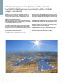
Sunny prospects for photovoltaic plants
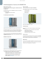
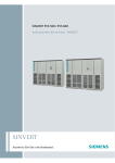
The SINVERT PVS 600Series central inverters from 500 to 2 520 kW:
compact, robust, durable
Whether on the roofs of large industrial facilities, in
ground-mounted PV systems, or solar power plants
– you can now utilize the power of the sun even more
efficiently: with the new three-phase SINVERT PVS
600Series photovoltaic inverters.
With these inverters you can achieve a peak efficiency of
98.7% and a European efficiency of 98.4% when converting
solar power for feeding into the grid.
The SINVERT PVS inverters operate in inverter stations
according to the Siemens master-slave concept that has
been proven in use now for more than a decade, and that
stands for maximum plant availability, a particularly long
service life, and optimized efficiency.
Peak efficiency you can count on!
2
Sunny prospects for photovoltaic plants
Inverter stations with SINVERT PVS inverters are system
solutions for simple and fast implementation of photovoltaic
power plants. Additional system components and accessories
required for this purpose are available.
The SINVERT Select dimensioning program helps to find
the best possible configuration for a photovoltaic plant.
A modular service concept means that services can be
tailored to different needs as required.
The SINVERT PVS inverters are characterized by their
ruggedness and longevity, which we back up with a
five-year manufacturer's warranty as standard.
© Siemens AG 2012
Contents
text
Introduction
Sunny prospects for photovoltaic plants . . . . . . . . . . . 2
SINVERT PVS 600Series central inverters . . . . . . . . . 4
Features and advantages at a glance. . . . . . . . . . . . . . 4
Technical data of the PVS500 (IEC) . . . . . . . . . . . . . . . 6
Technical data of the PVS585 (IEC) . . . . . . . . . . . . . . . 7
Technical data of the PVS600 (IEC) . . . . . . . . . . . . . . . 8
Technical data of the PVS630 (IEC) . . . . . . . . . . . . . . . 9
Options for SINVERT PVS 600Series inverters . . . . . . 10
SINVERT PVS in power plants . . . . . . . . . . . . . . . . . 12
How solar power is fed into the AC grid. . . . . . . . . . . 12
SINVERT PVS CombinerBoxes for bundling:
single-stage concept, two-stage concept . . . . . . . . . 12
IEC-compliant inverter stations . . . . . . . . . . . . . . . . . 14
- Master-slave system with SINVERT PVS . . . . . . . . . . 15
- Medium-voltage components . . . . . . . . . . . . . . . . . 15
Establishing communication with PVS and system
components . . . . . . . . . . . . . . . . . . . . . . . . . . . . . . . . 16
- SINVERT PVS ComBox 100 . . . . . . . . . . . . . . . . . . . . 16
- SINVERT PVS ControlBox 300 . . . . . . . . . . . . . . . . . . 16
- SINVERT PVS ComBox 200 . . . . . . . . . . . . . . . . . . . . 18
- SINVERT PVS WeatherStation 200 . . . . . . . . . . . . . . 18
PV plant dimensioning with SINVERT Select . . . . . 20
PV plant monitoring . . . . . . . . . . . . . . . . . . . . . . . . 21
with WinCC . . . . . . . . . . . . . . . . . . . . . . . . . . . . . . . . . 21
with SINVERT WebMonitor . . . . . . . . . . . . . . . . . . . . . 22
Selection and ordering data for devices and
accessories . . . . . . . . . . . . . . . . . . . . . . . . . . . . . . . . 23
Service & Support . . . . . . . . . . . . . . . . . . . . . . . . . . . 26
Spare parts service:
On-demand spare parts delivery, PVS SparesKits. . . . 28
Service calls:
Commissioning, On-site service, Maintenance . . . . . 28
Service contracts . . . . . . . . . . . . . . . . . . . . . . . . . . . . 29
- SINVERT PVS SparesContract . . . . . . . . . . . . . . . . . . 30
- SINVERT PVS WarrantyExtension . . . . . . . . . . . . . . . 30
- SINVERT PVS MaintenanceContract . . . . . . . . . . . . . 31
- SINVERT PVS FullServiceContract . . . . . . . . . . . . . . . 31
Sunny prospects for photovoltaic plants
3
© Siemens AG 2012
SINVERT PVS 600Series central inverters
Features and advantages at a glance
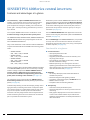
Transformerless, 3-phase SINVERT PVS inverters are
reliable, grid-compatible and cost-effective photovoltaic
inverters which are used to convert solar energy into
grid-compliant AC voltage for feeding into conventional
power grids – thereby achieving peak efficiency levels of
up to 98.7%.
Photovoltaic plants in which SINVERT PVS inverters are used
can be monitored and controlled with the WinCC visualization
system installed on a Windows PC. WinCC gives transparency
to the status and energy flow of the entire plant, from the
photovoltaic array and the inverters right up to the grid
connection (see page 21).
The compact SINVERT PVS inverters are ideal for use in
medium and large-scale photovoltaic power plants.
The free SINVERT WebMonitor web application can also be
used for monitoring the photovoltaic plant with SINVERT PVS
inverters (see page 22).
The SINVERT PVS500, SINVERT PVS585, SINVERT PVS600 and
SINVERT PVS630 inverters are grouped together under the
name "SINVERT PVS 600Series".
They consist of between 1 and 4 subunits and are available for
outputs of between 500 and 2 520 kW in the following power
levels:
– SINVERT PVS500:
500, 1 000, 1 500, 2 000 kW
– SINVERT PVS585:
585, 1 170, 1 755, 2 340 kW
– SINVERT PVS600:
600, 1 200, 1 800, 2 400 kW
– SINVERT PVS630:
630, 1 260, 1 890, 2 520 kW
The IEC-compliant devices are also available already integrated
in an inverter station (with two to four subunits), including
medium-voltage components. Besides SINVERT PVS and
inverter stations, additional system components and
accessories are available for implementing photovoltaic
power plants according to IEC standards (see page 12).
With the MobileApp of the SINVERT WebMonitor, it is possible
to call up the current and historical data of the selected
photovoltaic plant remotely at any time, using a smartphone
or tablet computer (see page 22).
Your benefits at a glance:
■
Cost-effectiveness
– Good price/performance ratio
– Low installation costs
– High plant yields thanks to maximum efficiency over
very large power ranges
– Low operating costs thanks to the robust, durable
and low-maintenance design
– Reduced operating costs throughout the entire
operating period thanks to the master-slave principle
with rotating master, in which up to four inverter subunits are interconnected (see page 15)
■
Reliability
– Use of fully developed, tried-and-tested industrial
standard components
– Automatic diagnosis and signaling of faults
– Competent, professional support, worldwide service
– Modular service concept
– Compliance with the relevant guidelines
■
Transparency
– Central unit of the photovoltaic plant
– Automatic diagnostics on site or by means of remote
monitoring
– Pixel-graphics display with touch screen on the front
of the control cabinet enables simple and intuitive
operation and visualization of infeed power data and
other information
The modularity of the series and the free SINVERT Select
dimensioning software allow flexible planning of photovoltaic
plants (see page 20).
To obtain early warning of faults and creeping change due to
aging and wear, monitoring and control of a PV power plant
via a central control room is absolutely essential. Only in this
way can the operator initiate repairs and maintenance
measures at an early stage and thus avoid costly downtimes.
Central monitoring and control is therefore also an essential
part of a preventive maintenance system.
4
SINVERT PVS 600Series central inverters
© Siemens AG 2012
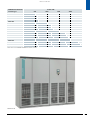
SINVERT PVS 600Series
Inverter type
Power / kW
500
1000
1500
2000
PVS500
PVS585
PVS600
PVS630
PVS1000
PVS1170
PVS1200
PVS1260
PVS1500
PVS1755
PVS1800
PVS1890
PVS2000
PVS2340
PVS2400
PVS2520
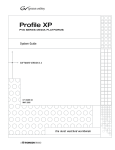
Power levels of the SINVERT PVS 600Series central inverters
SINVERT PVS 600Series central inverter (subunit)
SINVERT PVS 600Series central inverters
5
© Siemens AG 2012
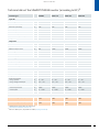
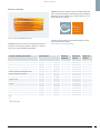
Technical data of the SINVERT PVS500 inverter (according to IEC)1)
Inverter type
PVS500
PVS1000
PVS1500
PVS2000
V
450 ... 750
450 ... 750
450 ... 750
450 ... 750
Input DC
MPP voltage
Maximum input
voltage2)
V
820
820
820
820
Minimum input voltage
V
450
450
450
450
Rated input power
kW
513
1 026
1 539
2 052
Maximum input current
A
1 103
2 206
3 309
4 412
3
6
9
12
368
368
368
368
Type 2
Type 2
Type 2
Type 2
Number of DC inputs
Maximum current per DC input
A
Surge arrester
Output AC
Grid connection
50/60 Hz 288 V 3 AC
50/60 Hz 288 V 3 AC
50/60 Hz 288 V 3 AC
50/60 Hz 288 V 3 AC
Rated power
kW
500
1 000
1 500
2 000
Maximum output current
A
1 002
2 004
3 006
4 008
Line voltage
V
244.8 ... 316.8
244.8 ... 316.8
244.8 ... 316.8
244.8 ... 316.8
Power factor, inductive
0.8
0.8
0.8
0.8
Power factor, capacitive
0.8
0.8
0.8
0.8
Efficiency
European efficiency factor
%
98.1
98.3
98.3
98.3
CEC efficiency factor
%
98.2
98.3
98.3
98.3
Maximum efficiency factor
%
98.4
98.4
98.4
98.4
1
2
3
4
Further data
Number of subunits
Dimensions (H/W/D) per subunit
mm
2 100 x 2 700 x 730
2 100 x 2 700 x 730
2 100 x 2 700 x 730
2 100 x 2 700 x 730
Weight per subunit
kg
2 085
2 085
2 085
2 085
Ambient temperature
- during operation
- during storage and transport
°C
°C
0 ... +50
-25 ... +70
0 ... +50
-25 ... +70
0 ... +50
-25 ... +70
0 ... +50
-25 ... +70
Relative humidity
%
0 ... 95
0 ... 95
0 ... 95
0 ... 95
Installation altitude
- maximum permissible
- at rated power
m
m
2 000
0 ... 1 000
2 000
0 ... 1 000
2 000
0 ... 1 000
2 000
0 ... 1 000
Ethernet
Ethernet
Ethernet
Ethernet
Order number (grid frequency 50 Hz)
6AG3111-1AH003AB0
6AG3111-1AH103AB0
6AG3111-1AH203AB0
6AG3111-1AH303AB0
Order number (grid frequency 60 Hz)
6AG3111-2AH003AB0
6AG3111-2AH103AB0
6AG3111-2AH203AB0
6AG3111-2AH303AB0
Data interface
Order number
1)
2)
6
Detailed technical information can be found at:
http://support.automation.siemens.com
With the 1 000 V option, expandable to 1 000 V (see page 10 and 24).
SINVERT PVS 600Series central inverters
© Siemens AG 2012
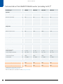
Technical data of the SINVERT PVS585 inverter (according to IEC)1)
Inverter type
PVS585
PVS1170
PVS1755
PVS2340
V
530 ... 750
530 ... 750
530 ... 750
530 ... 750
Input DC
MPP voltage
Maximum input
voltage2)
V
820
820
820
820
Minimum input voltage
V
530
530
530
530
Rated input power
kW
598
1 196
1 794
2 392
Maximum input current
A
1 104
2 208
3 312
4 416
3
6
9
12
368
368
368
368
Type 2
Type 2
Type 2
Type 2
Number of DC inputs
Maximum current per DC input
A
Surge arrester
Output AC
Grid connection
50/60 Hz 340 V 3 AC
50/60 Hz 340 V 3 AC
50/60 Hz 340 V 3 AC
50/60 Hz 340 V 3 AC
Rated power
kW
585
1 170
1 755
2 340
Maximum output current
A
995
1 990
2 985
3 980
Line voltage
V
289 ... 374
289 ... 374
289 ... 374
289 ... 374
Power factor, inductive
0.8
0.8
0.8
0.8
Power factor, capacitive
0.8
0.8
0.8
0.8
Efficiency
European efficiency factor
%
98.2
98.4
98.4
98.4
CEC efficiency factor
%
98.3
98.3
98.4
98.4
Maximum efficiency factor
%
98.6
98.6
98.6
98.6
1
2
3
4
Further data
Number of subunits
Dimensions (H/W/D) per subunit
mm
2 100 x 2 700 x 730
2 100 x 2 700 x 730
2 100 x 2 700 x 730
2 100 x 2 700 x 730
Weight per subunit
kg
2 085
2 085
2 085
2 085
Ambient temperature
- during operation
- during storage and transport
°C
°C
0 ... +50
-25 ... +70
0 ... +50
-25 ... +70
0 ... +50
-25 ... +70
0 ... +50
-25 ... +70
Relative humidity
%
0 ... 95
0 ... 95
0 ... 95
0 ... 95
Installation altitude
- maximum permissible
- at rated power
m
m
2 000
0 ... 1 000
2 000
0 ... 1 000
2 000
0 ... 1 000
2 000
0 ... 1 000
Ethernet
Ethernet
Ethernet
Ethernet
Order number (grid frequency 50 Hz)
6AG3111-1AH007AB0
6AG3111-1AH107AB0
6AG3111-1AH207AB0
6AG3111-1AH307AB0
Order number (grid frequency 60 Hz)
6AG3111-2AH007AB0
6AG3111-2AH107AB0
6AG3111-2AH207AB0
6AG3111-2AH307AB0
Data interface
Order number
1)
2)
Detailed technical information can be found at:
http://support.automation.siemens.com
With the 1 000 V option, expandable to 1 000 V (see page 10 and 24).
SINVERT PVS 600Series central inverters
7
© Siemens AG 2012
Technical data of the SINVERT PVS600 inverter (according to IEC)1)
Inverter type
PVS600
PVS1200
PVS1800
PVS2400
V
570 ... 750
570 ... 750
570 ... 750
570 ... 750
Input DC
MPP voltage
Maximum input
voltage2)
V
820
820
820
820
Minimum input voltage
V
570
570
570
570
Rated input power
kW
613
1 226
1 839
2 452
Maximum input current
A
1 104
2 208
3 312
4 416
3
6
9
12
368
368
368
368
Type 2
Type 2
Type 2
Type 2
Number of DC inputs
Maximum current per DC input
A
Surge arrester
Output AC
Grid connection
50/60 Hz 370 V 3 AC
50/60 Hz 370 V 3 AC
50/60 Hz 370 V 3 AC
50/60 Hz 370 V 3 AC
Rated power
kW
600
1 200
1 800
2 400
Maximum output current
A
936
1 872
2 808
3 744
Line voltage
V
314.5 ... 407
314.5 ... 407
314.5 ... 407
314.5 ... 407
Power factor, inductive
0.8
0.8
0.8
0.8
Power factor, capacitive
0.8
0.8
0.8
0.8
Efficiency
European efficiency factor
%
98.4
98.6
98.6
98.6
CEC efficiency factor
%
98.5
98.6
98.6
98.6
Maximum efficiency factor
%
98.7
98.7
98.7
98.7
1
2
3
4
Further data
Number of subunits
Dimensions (H/W/D) per subunit
mm
2 100 x 2 700 x 730
2 100 x 2 700 x 730
2 100 x 2 700 x 730
2 100 x 2 700 x 730
Weight per subunit
kg
2 085
2 085
2 085
2 085
Ambient temperature
- during operation
- during storage and transport
°C
°C
0 ... +50
-25 ... +70
0 ... +50
-25 ... +70
0 ... +50
-25 ... +70
0 ... +50
-25 ... +70
Relative humidity
%
0 ... 95
0 ... 95
0 ... 95
0 ... 95
Installation altitude
- maximum permissible
- at rated power
m
m
2 000
0 ... 1 000
2 000
0 ... 1 000
2 000
0 ... 1 000
2 000
0 ... 1 000
Ethernet
Ethernet
Ethernet
Ethernet
Order number (grid frequency 50 Hz)
6AG3111-1AH000AB0
6AG3111-1AH100AB0
6AG3111-1AH200AB0
6AG3111-1AH300AB0
Order number (grid frequency 60 Hz)
6AG3111-2AH000AB0
6AG3111-2AH100AB0
6AG3111-2AH200AB0
6AG3111-2AH300AB0
Data interface
Order number
1)
2)
8
Detailed technical information can be found at:
http://support.automation.siemens.com
With the 1 000 V option, expandable to 1 000 V (see page 10 and 24).
SINVERT PVS 600Series central inverters
© Siemens AG 2012
Technical data of the SINVERT PVS630 inverter (according to IEC)1)
Inverter type
PVS630
PVS1260
PVS1890
PVS2520
V
570 ... 750
570 ... 750
570 ... 750
570 ... 750
Input DC
MPP voltage
Maximum input
voltage2)
V
820
820
820
820
Minimum input voltage
V
570
570
570
570
Rated input power
kW
643
1 286
1 929
2 572
Maximum input current
A
1 104
2 208
3 312
4 416
3
6
9
12
368
368
368
368
Type 2
Type 2
Type 2
Type 2
Number of DC inputs
Maximum current per DC input
A
Surge arrester
Output AC
Grid connection
50/60 Hz 370 V 3 AC
50/60 Hz 370 V 3 AC
50/60 Hz 370 V 3 AC
50/60 Hz 370 V 3 AC
Rated power
kW
630
1 260
1 890
2 520
Maximum output current
A
985
1 970
2 955
3 940
Line voltage
V
314.5 ... 407
314.5 ... 407
314.5 ... 407
314.5 ... 407
Power factor, inductive
0.8
0.8
0.8
0.8
Power factor, capacitive
0.8
0.8
0.8
0.8
Efficiency
European efficiency factor
%
98.3
98.5
98.5
98.5
CEC efficiency factor
%
98.4
98.5
98.5
98.5
Maximum efficiency factor
%
98.7
98.7
98.7
98.7
1
2
3
4
Further data
Number of subunits
Dimensions (H/W/D) per subunit
mm
2 100 x 2 700 x 730
2 100 x 2 700 x 730
2 100 x 2 700 x 730
2 100 x 2 700 x 730
Weight per subunit
kg
2 085
2 085
2 085
2 085
Ambient temperature
- during operation
- during storage and transport
°C
°C
0 ... +50
-25 ... +70
0 ... +50
-25 ... +70
0 ... +50
-25 ... +70
0 ... +50
-25 ... +70
Relative humidity
%
0 ... 95
0 ... 95
0 ... 95
0 ... 95
Installation altitude
- maximum permissible
- at rated power
m
m
2 000
0 ... 1 000
2 000
0 ... 1 000
2 000
0 ... 1 000
2 000
0 ... 1 000
Ethernet
Ethernet
Ethernet
Ethernet
Order number (grid frequency 50 Hz)
6AG3111-1AH008AB0
6AG3111-1AH108AB0
6AG3111-1AH208AB0
6AG3111-1AH308AB0
Order number (grid frequency 60 Hz)
6AG3111-2AH008AB0
6AG3111-2AH108AB0
6AG3111-2AH208AB0
6AG3111-2AH308AB0
Data interface
Order number
1)
2)
Detailed technical information can be found at:
http://support.automation.siemens.com
With the 1 000 V option, expandable to 1 000 V (see page 10 and 24).
SINVERT PVS 600Series central inverters
9
© Siemens AG 2012
Options for SINVERT PVS 600Series inverters
Basic versions and options
1 000 V option
The SINVERT PVS 600Series of inverters can be adapted and
expanded by means of options in order to meet the individual
needs of the plant.
The 1 000 V option increases the maximum permissible input
voltage of the SINVERT PVS inverter from 820 to 1 000 V.
Provision of this option ensures that the PV plant will enter
operation smoothly even with voltages in excess of 820 V
which can occur, for example, on cold days or in arrays
containing thin-film modules. The option thus maximizes the
potential yield of the installation. The MPP voltage range of
the SINVERT PVS inverter is not changed.
The following 4 options are available:
– PV array grounding
– 1 000 V option
– Symmetry monitoring
– Cabinet heating
Symmetry monitoring
PV array grounding
In most cases, PV systems constitute a DC IT system. In a DC IT
system, neither the positive nor negative pole is grounded.
When using certain module types, however, either a positive
or negative grounding of the PV generator is required. It is
only by this grounding that damage to modules and a steady
loss of power can be prevented, i.e. that the maximum yield
can be obtained on a continuous basis.
The "PV array grounding positive pole" option allows functional
grounding of the positive conductor inside the SINVERT PVS
inverter if this is a requirement of the photovoltaic modules
used (e.g. large number of thick-film modules).
The "PV array grounding negative pole" option allows
functional grounding of the negative conductor inside the
SINVERT PVS inverter if this is a requirement of the photovoltaic
modules used (e.g. large number of thin-film modules).
PV systems no longer constitute a DC IT system when their
modules are grounded. For safety reasons, the PV system
must be fenced in and designated as an electrical operating
area. Only qualified electricians may be granted access.
Grounding an active conductor (positive pole or negative
pole) means that the inverter's insulation measuring function
no longer works in the normal way. A hazardous current can
start to flow as soon as the first insulation damage occurs. For
this reason, in the case of positive pole grounding, the current
between the positive pole and ground is measured, and in the
case of negative pole grounding, the current between the
negative pole and ground. When the current increases to a
critical level, the ground connection is automatically separated.
10
SINVERT PVS 600Series central inverters
The "symmetry monitoring" option measures the normalized
currents at the DC inputs internally and cross-compares the
values. If this comparison indicates deviations over time, a
message is generated. The message can be used as a guide to
localizing faults early in sections of the PV generator (e.g. cell
failure).
Cabinet heating
The "cabinet heating" option minimizes the risk of condensation forming on the moisture-sensitive components in the
SINVERT PVS photovoltaic inverter at low ambient temperatures. Reliable operation and maximum energy yields to the
grid are dependent on compliance with the operating temperature range prescribed for the relevant SINVERT PVS inverter.
This function is recommended for locations at which the
ambient temperature can drop below 7 °C.
Order numbers for the options
Each of the four options has its own order number which is
to be specified in addition to the order number of the basic
version (see "Selection and ordering data", page 23).
© Siemens AG 2012
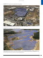
SINVERT PVS inverters for industrial roof systems
A SINVERT PVS2000 is used for the Aspropyrgos 2 MW roof system erected in Greece in 2011 for Big Solar
SINVERT PVS inverters for solar power plants
The 31 MW solar power plant at Les Mées in France was constructed in 2010/2011 for Eco Delta and connected to the grid in August 2011. For this project,
Siemens acted as a general contractor with an all-in-one concept from a single source, including maintenance, operation and warranty services.
SINVERT PVS500 inverters are in use at this PV solar plant with 112 400 solar modules installed over an area of 66 hectares. The SINVERT Select software
was used for the plant dimensioning, and the plant is monitored with WinCC software.
SINVERT PVS 600Series central inverters
11
© Siemens AG 2012
SINVERT PVS in power plants
Link between solar power and public AC grid
How solar power is fed into the AC grid
Sunlight is transformed into solar energy in the photovoltaic
modules. The direct current obtained is bundled in the field
with the aid of SINVERT PVS CombinerBoxes and then fed into
a SINVERT PVS inverter (see diagrams on this page).
The alternating current supplied by the inverters is transformed
by medium-voltage transformers into the higher voltages of
20 kV, for example, that are needed for feed-in to the grid.
With the two-stage concept, the module strings are initially
brought together in the SINVERT PVS CombinerBoxes (first
stage). The outputs of these SINVERT PVS CombinerBoxes
are then connected to other SINVERT PVS CombinerBoxes
(second stage). The outputs of the SINVERT PVS CombinerBoxes
of the second stage are then connected to the inputs of the
SINVERT PVS inverters or inverter stations. The advantage of
this two-stage concept is that power losses are reduced thanks
to the increased cable cross-sections.
Photovoltaic modules
The inverters and the transformers are in a protected location in
inverter stations, as is the optional medium-voltage switchgear,
which allows energy to be distributed and fed into the
medium-voltage grid (see diagram on page 14).
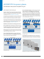
SINVERT PVS CombinerBoxes for bundling partial currents
Module strings can be "collected" and their energy transported
to the SINVERT PVS inverter or inverter station using a singlestage or two-stage connection concept:
SINVERT PVS
CombinerBoxes 108
SINVERT PVS
CombinerBoxes 204
Photovoltaic array
RE10_00026b
With the SINVERT PVS CombinerBox, the individual strings of
the photovoltaic generator are collected in the field, connected
in parallel and the energy conveyed via large cross-section
cables to the SINVERT PVS inverter or the inverter station.
Service room
SINVERT PVS inverters
With the single-stage concept, the energy supplied by the
module strings to the inputs of the SINVERT PVS CombinerBoxes is transported directly to the SINVERT PVS inverter or the
inverter station via one output in each case.
SINVERT PVS
CombinerBoxes 120
Photovoltaic array
The SINVERT PVS CombinerBoxes 108, 120, 124 with eight,
twenty, and twenty-four inputs are used in the first stage. The
CombinerBox 204 with four inputs is used in the second stage.
RE10_00027a
Photovoltaic modules
Bundling of the solar direct current using SINVERT PVS CombinerBoxes
(two-stage concept)
Service room
SINVERT PVS inverters
Bundling of the solar direct current using SINVERT PVS CombinerBoxes
(single-stage concept)
SINVERT PVS CombinerBoxes 124, 204, 120, 108 (from left to right)
12
SINVERT PVS in power plants
© Siemens AG 2012
The SINVERT PVS CombinerBoxes are designed for vertical
mounting.
The output side of the SINVERT PVS CombinerBoxes can be
optionally equipped with or without a switch disconnector.
CombinerBoxes with switch disconnectors are capable of
disconnecting the connected section of the photovoltaic
generator from the SINVERT PVS inverter, e.g. for maintenance work.
SINVERT PVS CombinerBox
108
120
124
204
Number of inputs
8
20
24
4
Maximum protection per input
15 A
20 A
Voltage
1 000 V
Switch disconnector
optional
Surge arrester
opt.
160 A
---
The SINVERT PVS CombinerBox 108 is optionally available
with or without overvoltage protection, which is designed
to protect the modules.
The inputs of the SINVERT PVS CombinerBoxes are protected by fuses. The fuses are not included in the scope of supply of the SINVERT PVS CombinerBox and must be ordered
separately (see Selection and ordering data on page 25).
The SINVERT PVS CombinerBox has IP54 degree of protection
and is rated for voltages up to 1 000 V.
SINVERT PVS in power plants
13
© Siemens AG 2012
IEC-compliant inverter stations
The inverter stations are system solutions for fast, simple
implementation of turnkey photovoltaic stations. They are
ideally suited for photovoltaic power plants ("Power Plant"
segment) with outputs of 1 000 kW upwards.
They are typically employed in ground-mounted systems.
Inverter stations contain two to four SINVERT PVS inverters
and, depending on the selected type, also medium-voltage
switchgear and medium-voltage transformers. They are
designed to convert solar energy reliably and cost-effectively
into grid-compatible energy for infeed into conventional
power grids.
All individual components of the inverter stations, such as
SINVERT PVS inverters and medium-voltage transformers, are
technically fully developed, designed for extreme ruggedness
electrical and mechanical properties and completely wired
and tested.
The inverter stations are available in power levels from
1 000 to 2 520 kW with 2, 3 or 4 inverter subunits comprising
the PVS500, PVS585, PVS600 and PVS630 inverters
(see diagram on page 5).
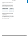
Inverter station
SINVERT PVS inverters
Medium-voltage transformer
Medium-voltage switchgear
RE10_00025b
Basic interconnection of components in the inverter station in a configuration containing a SINVERT PVS2000, PVS2340, PVS2400 or PVS2520 inverter
(each consisting of four SINVERT PVS500, PVS585, PVS600 or PVS630 subunits)
14
SINVERT PVS in power plants
© Siemens AG 2012
Intensity of solar irradiation
morning
noon
evening
night
1st day
2nd day
RE10_00034
3rd day
4th day
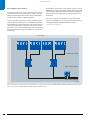
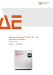
The inverters integrated in the inverter stations operate with a rotating master according to the master-slave principle.
The diagram shows in simplified form that the master moves to the next inverter each day (see left column). In actual fact, the inverter with the fewest
operating hours is started as the master on the next day.
Master-slave system with SINVERT PVS
The SINVERT PVS inverters integrated in the inverter stations
operate with a "rotating master" according to the master-slave
principle. This is a master-slave system comprising between
two and four interconnected inverter subunits. It employs an
ingenious process to connect or disconnect inverter subunits,
depending on the level of solar irradiation (determined
according to the sun's path, cloud conditions, etc.). The master is started up first and operates even when irradiation levels
are low. As irradiation levels increase, the next inverter
subunit is switched in as a slave when a set switching threshold is exceeded. Depending on the configuration, up to three
slaves can be switched in. As irradiation levels drop again, the
subunits are disconnected in stages. One advantage of the
master-slave principle is that the efficiency factor is higher
when irradiation levels (which determine the PV generator
output) are low than it would be if only a single inverter were
used.
In master-slave systems, the "rotating master" function always
starts the inverter subunit with the fewest operating hours as
the master. In this way, the total operating hours are evenly
distributed among all the subunits.
■
Individual components of the inverter stations
– SINVERT PVS inverters according to IEC and their
components (for further information see Catalog
RE10 "Inverters and Components for Photovoltaic
Installations")
– AC distribution for voltage supply, control and
monitoring of the components.
– Medium-voltage transformer
– Medium-voltage switchgear
For technical data on the fully configured inverter stations,
the AC distribution, the medium-voltage transformer and the
medium-voltage switchgear, please contact your local sales
partner:
www.siemens.com/sinvert/partner
Medium-voltage transformer
The medium-voltage transformer transforms the low voltage
supplied by the SINVERT PVS photovoltaic inverter into a
defined medium voltage of 20 kV, for example, for feeding
into the grid.
Several medium-voltage transformer brands are available,
e.g. the loss-optimized GEAFOL medium-voltage transformer
(cast-resin two-tier transformer), which has been specially
designed for photovoltaic applications.
Detailed information about GEAFOL medium-voltage transformers can be found in the Catalog TV 1 "GEAFOL cast-resin
transformers 100 to 16 000 kVA".
Medium-voltage switchgear
The medium-voltage switchgear is available as an option.
It distributes energy and feeds power into the medium-voltage
network.
Detailed information about medium-voltage switchgear can
be found in the Catalog HA 40.2 "Switchgear Type 8DJH for
Secondary Distribution Systems up to 24 kV, Gas-Insulated".
SINVERT PVS in power plants
15
© Siemens AG 2012
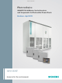
Establishing communication with PVS and system components
Communication via Industrial Ethernet and plant monitoring with WinCC
Internet
Industrial Ethernet
SCALANCE S
VPN Router
DSL-Router
WinCC
WebNavigator
Inverter - Stations 2-n
Inverter - Station 1
Inverter
SINVERT PVS
Inverter
SINVERT PVS
SINVERT PVS
WeatherStation 200
WinCC PC
SINVERT PVS
ComBox 100
SINVERT PVS
ComBox 100
Weather sensors
Industrial Ethernet FOC ring
Circle control
receiver
EVU
0%
SINVERT PVS
ControlBox 300
100 %
RE10_00029d
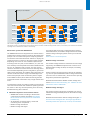
Integration of SINVERT PVS inverters into a photovoltaic plant with communication via an Ethernet network, solar PV plant control by means of the
SINVERT PVS ControlBox 300, and monitoring with WinCC
The inverter stations have an Ethernet interface. If the inverter
station is linked to an Ethernet network, this interface permits
the exchange of data between the inverter station(s) and the
WinCC visualization system on a Microsoft Windows PC. The
data server on the ControlBox 300 collects the data from all
the inverters.
SINVERT PVS ControlBox 300
The purpose of the SINVERT PVS ControlBox 300 is to regulate
the active and reactive power of a photovoltaic plant containing
SINVERT PVS inverters and to ensure compliance with legal
requirements (according to the current amendment of the
Renewable Energy Act (EEG), in force since January 2009).
Remote access to the WinCC visualization system is also possible
over the Internet if the WinCC WebNavigator software has
been installed.
SINVERT PVS ComBox 100
The SINVERT PVS ComBox 100 communications box interconnects the inverter stations (in linear or ring topologies) with
copper or fiber-optic LAN cabling and also connects networkcapable components in the inverter stations, e.g. SINVERT PVS
inverters.
The ComBox 100 has the following connection options:
– 4 x RJ45 ports
– 2 x fiber-optic ports, for cable lengths up to 5 km
SINVERT PVS ControlBox 300
16
SINVERT PVS in power plants
© Siemens AG 2012
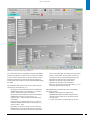
Regulation of the PV plant according to BDEW Guideline and the current amendment of the Renewable Energy Act (EEG) by means of
SINVERT PVS ControlBox 300 displayed with WinCC
The "Generating Plants in the Medium-Voltage Grid" BDEW
guideline stipulates this requirement for all systems feeding
in at the medium-voltage level. Its primary benefit is that it
enables grid operators to limit the output of the plant by
remote means in accordance with § 6 of the Renewable Energy
Act 2009.
The ControlBox 300 offers a wide range of open-loop and
closed-loop control functions, e.g.:
– Specification of a fixed active power for all individual
SINVERT PVS inverters in the PV plant, e.g. setpoint
value = 2 MW (active power fixed value)
– Specification of a fixed reactive power for all individual
SINVERT PVS inverters in the PV plant, e.g.
setpoint value = 100 kvar inductive (reactive power
fixed value)
– Specification of a fixed power factor cos ϕ for all
individual SINVERT PVS inverters in the PV plant, e.g.
setpoint value = -0.95
– Regulation of the active power for the individual
SINVERT PVS inverters in the PV plant as a function of
the active power actually measured at the grid infeed
–
–
–
–
point, to 0%, 30%, 60%, and 100% of the rated active
power of the PV plant. (Active power reduction in
accordance with § 6 of the Renewable Energy Act
Regulation according to Q(U) characteristic
Regulation according to Q(t) characteristic
Regulation according to P(f) characteristic
Ramps for system ramp-up and ramp-down, i.e. continuously approaching the setpoint
The SINVERT PVS ControlBox 300 offers the following
connection options:
– SIMATIC components with digital inputs
– SENTRON PAC3200 Power Monitoring Device for
measuring actual values at the grid feed-in point
– 4 x RJ45 ports
– 2 x fiber-optic ports, for cable lengths up to 5 km
SINVERT PVS in power plants
17
© Siemens AG 2012
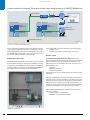
Communication via Industrial Ethernet and plant monitoring by means of SINVERT WebMonitor
Internet
Industrial Ethernet
SCALANCE S
VPN Router
Inverter - Station 1
DSL-Router
SINVERT WebMonitor
Inverter - Stations 2-n
Inverter
SINVERT PVS
Inverter
SINVERT PVS
Client
SINVERT PVS
WeatherStation 200
SINVERT PVS
ComBox 200
SINVERT PVS
ComBox 100
Weather sensors
Industrial Ethernet FOC ring
RE10_00033d
Integration of SINVERT PVS inverters into a photovoltaic plant without solar PV plant control with communication via an Ethernet network and
monitoring by means of SINVERT WebMonitor
In the configuration example shown in the diagram without
solar PV plant control and with plant monitoring by means of
SINVERT WebMonitor, the required industrial PC is provided in
the SINVERT PVS ComBox 200, which must be used in one of
the inverter stations instead of a ComBox 100.
The ComBox 200 contains the following main components:
– 4 x RJ45 ports
– 2 x fiber-optic ports, for cable lengths up to 5 km
SINVERT PVS ComBox 200
The SINVERT PVS WeatherStation 200 acquires data
about the weather at the photovoltaic plant site. This weather
data is recorded by sensors connected to the station. The
following sensors are included in the scope of supply of the
WeatherStation 200:
– Insolation
– Module temperature
– Ambient temperature
Additional sensors such as wind speed or rain sensors can be
connected.
The SINVERT PVS ComBox 200 has the same scope of functions
as the ComBox 100, but also provides the capability of transferring data from the SINVERT PVS inverters and from additional
network-capable components to the SINVERT WebMonitor
web application for monitoring photovoltaic plants.
Weather station
Using the acquired data, it is possible to perform and transmit
extremely precise weather recordings. The target yield of the
photovoltaic plant can then be calculated from the recorded
weather data. By comparing the actual and target yield, it is
possible to make a quick assessment of the plant's operating
performance and detect any irregularities very promptly.
The SINVERT PVS WeatherStation 200 offers the following
connection options:
– 6 analog inputs for the sensors
– PROFINET communications interface
SINVERT PVS ComBox 200
18
SINVERT PVS in power plants
© Siemens AG 2012
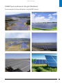
SINVERT puts sunshine into the grid. Worldwide.
Some examples of solar power plants using SINVERT inverters
Les Mées (France): 31 MW (2010/2011)
Desoto (Florida, USA): 27 MW (2009)
Beneixama (Spain): 20 MW (2007)
Serpa (Portugal): 11 MW (2007)
Shi Lin (China): 10 MW (2010)
Dobre Polé (Czech Republic): 4 MW (2010)
SINVERT PVS in power plants
19
© Siemens AG 2012
PV plant dimensioning with SINVERT Select
For fast and easy dimensioning
The key features of SINVERT Select are:
■
The structure and workflow of the SINVERT Select
program means that photovoltaic plants containing
SINVERT inverters can be dimensioned quickly and simply in just a few steps.
■
The SINVERT Select program can be operated intuitively
thanks to the clear structure of the graphical user interface.
■
Extensive database for location selection, containing
over 400 locations in more than 30 countries
■
Database containing all the currently available SINVERT
inverters
■
Extensive database for module selection, which currently
contains over 6 700 different photovoltaic modules
available on the market (individual expansion is possible)
■
All the necessary data for dimensioning (locations,
SINVERT inverters, and PV modules) is constantly
updated.
■
The online update function of the SINVERT Select program
means that the latest version of the program is always
installed on your computer.
■
Numerous options for specifying the power (specification
of area, DC power, and number of modules)
■
Selectable calculation modes (automatic/manual
dimensioning, number of photovoltaic modules per
string, etc.)
■
Clear display of results of the possible configurations
depending on previously selected parameters
■
Project management
■
Creation of reports for presentation of calculation
results and printout
■
SINVERT Select also enables reactive power to be
accounted for when configuring inverters in accordance
with the Technical Guideline "Generating Plants in the
Medium-Voltage Grid" of the German Association of
Energy and Water Industries (BDEW).
■
Language support: English, German, French, Italian and
Spanish
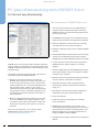
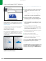
SINVERT Select: Proposed solution for dimensioning a photovoltaic plant,
including plant details
SINVERT Select is a free program which facilitates the dimensioning, analysis and optimization of photovoltaic plants with
SINVERT inverters and outputs from a few kilowatts up to the
megawatt range.
Two different methods can be employed to dimension a
photovoltaic plant with SINVERT inverters:
■
■
With the automatic dimensioning method, the
SINVERT Select program first uses the information you
enter (string/central inverter, location, photovoltaic
module, rated power, etc.) to automatically identify the
best possible inverter variant. For this variant, it
calculates the performance ratio (PR) and the potential
energy yield per annum. Individual configurations can
be compared, assessed and optimized on the basis of
these parameters.
With the manual dimensioning method, you can input
one or two SINVERT inverter types in addition to the
information about location, photovoltaic module, and
rated power. Optionally, their quantity can also be
specified.
After you have registered, you can download the
SINVERT Select program free of charge at:
www.siemens.com/sinvert-select
20
PV plant dimensioning with SINVERT Select
© Siemens AG 2012
PV plant monitoring
For an instant, up-to-date overview and
rapid intervention
PV plant monitoring with WinCC
The key features of WinCC are:
■
A clearly designed user interface provides an instant
overview of all key data of the managed plants,
subplants and inverters, e.g. states, energy production,
and income
■
Graphical representation of the monitored data (see
graphic on page 17)
■
Graphics with configurable content for quick visual
access to customized displays of received and/or
calculated data, e.g. sorted according to day, month,
year.
■
Alarms and messages for quick and simple troubleshooting
and for ensuring that remedial measures can be quickly
taken to minimize loss of earnings
■
Remote monitoring over the Internet with the
WinCC/WebNavigator option
■
Acquisition, long-term storage and display of current
and historical data
■
Export of archived data to Excel using the DataMonitor
option
■
Plant monitoring (e.g. detection and display of faults in
the photovoltaic generator through section-by-section
measurement of the whole plant)
■
Safeguarding of yield and optimum protection by
monitoring the insulation value
■
Messaging services using email and text messaging with
the WinCC/AlarmControlCenter option
■
Fault messages can be specifically configured for
customized operations management
■
Establishment of as many as 128 user groups, each with
up to 128 individual users, and assignment of different
authorization levels to the users and/or user groups are
possible
■
Representation of monitored plants on a map
Visualization and operation of photovoltaic plants with WinCC
WinCC (Windows Control Center) is a visualization system
which runs on Microsoft Windows. It is used to monitor and
control photovoltaic plants in which SINVERT inverters are
installed.
WinCC provides all the functions required to visualize and
operate PV plants, from the PV generator itself to the inverters
and grid connection. It can also acquire data (e.g. energy
yields) and store it on a long term basis, acquire, store and visualize alarms and messages, and provide data interfaces to
external systems.
WinCC can run on a Microsoft Windows PC that is connected
to the Industrial Ethernet network of the PV plant. Remote
access to the WinCC visualization system is also possible over
the Internet if the WinCC WebNavigator software has been
installed (see graphic on page 16).
SINVERT WinCC enables consistently scalable plant configurations – from small PV power plants up to the GW range.
In addition, our visualization system can be configured easily
and efficiently. The use of a standardized PV library allows
customer-specific adaptations to be carried out. WinCC is
configured individually according to customer requirements
and specific features of the plant. For more information,
please contact your regional sales partner.
www.siemens.com/sinvert/partner
PV plant monitoring
21
© Siemens AG 2012
PV plant monitoring with SINVERT WebMonitor
The key features of SINVERT WebMonitor
are:
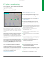
SINVERT WebMonitor for monitoring photovoltaic plants
■
Clear user interface layout provides a quick overview of
managed plants, subplants and inverters in a tree
structure.
■
Overview page (dashboard) and plant page provide
instant, up-to-date information about all key aspects of
the plants, subplants and inverters, e.g. states, energy
production (daily energy, total energy) and income.
■
Fault lists are provided to speed up and simplify
troubleshooting and to ensure that remedial measures
can be quickly taken to minimize loss of earnings.
■
Graphics with configurable content provide users with
quick visual access to customized displays of received
and/or calculated data, sorted according to day, month,
year and total.
■
Users can configure monitoring settings
(e.g. "daily energy deviation") and activate messaging
services (e.g. by e-mail) according to individual requirements to receive information about plant status, energy
production, income and irregularities.
■
User profiles can be defined so that plants and rights can
be individually assigned to users.
■
Display of current and historical data
■
Representation of monitored plants on a map
■
Language support: English, German, French, Italian,
Spanish, Czech, Greek and Romanian.
SINVERT WebMonitor is a Web application for monitoring
photovoltaic plants in which SINVERT inverters are used (see
graphic on page 18).
It is used for transmitting the states of the photovoltaic plant,
for displaying production and income, or optionally for
reporting any problems that arise.
SINVERT WebMonitor MobileApp
With the MobileApp of the SINVERT WebMonitor, it is possible
to call up the current and historical data of the selected
photovoltaic plant remotely at any time using a smartphone
or tablet computer.
If you are using SINVERT PVM und SINVERT PVS inverters
in your photovoltaic plant and you want to use
SINVERT WebMonitor as a plant monitor, you can register
and log in at:
www.siemens.com/sinvert/webmonitor
The SINVERT WebMonitor MobileApp is started by calling
the Internet address of the SINVERT WebMonitor from a
smartphone or tablet computer. The SINVERT WebMonitor
user name is used for the login.
SINVERT WebMonitor MobileApp
Left: Bar chart indicating daily AC power yield
Right: Bar chart indicating annual energy yield
22
PV plant monitoring
© Siemens AG 2012
Selection and ordering data
for devices and accessories
SINVERT PVS 600Series inverters
Product type
identification
Number of
masters/slaves
Active power
output (rated
value)
Output voltage
(rated value)
MPP voltage
Input voltage
(max. permissible)
kW
V
V
V
Order No.
SINVERT PVS inverters (IEC-compliant)
Grid frequency 50Hz (rated value)
PVS500
1M
500
288
450 ... 750
820
6AG3111-1AH00-3AB0
PVS585
1M
585
340
530 ... 750
820
6AG3111-1AH00-7AB0
PVS600
1M
600
370
570 ... 750
820
6AG3111-1AH00-0AB0
PVS630
1M
630
370
570 ... 750
820
6AG3111-1AH00-8AB0
PVS1000
1M, 1S
1 000
288
450 ... 750
820
6AG3111-1AH10-3AB0
PVS1170
1M, 1S
1 170
340
530 ... 750
820
6AG3111-1AH10-7AB0
PVS1200
1M, 1S
1 200
370
570 ... 750
820
6AG3111-1AH10-0AB0
PVS1260
1M, 1S
1 260
370
570 ... 750
820
6AG3111-1AH10-8AB0
PVS1500
1M, 2S
1 500
288
450 ... 750
820
6AG3111-1AH20-3AB0
PVS1755
1M, 2S
1 755
340
530 ... 750
820
6AG3111-1AH20-7AB0
PVS1800
1M, 2S
1 800
370
570 ... 750
820
6AG3111-1AH20-0AB0
PVS1890
1M, 2S
1 890
370
570 ... 750
820
6AG3111-1AH20-8AB0
PVS2000
1M, 3S
2 000
288
450 ... 750
820
6AG3111-1AH30-3AB0
PVS2340
1M, 3S
2 340
340
530 ... 750
820
6AG3111-1AH30-7AB0
PVS2400
1M, 3S
2 400
370
570 ... 750
820
6AG3111-1AH30-0AB0
PVS2520
1M, 3S
2 520
370
570 ... 750
820
6AG3111-1AH30-8AB0
Grid frequency 60Hz (rated value)
PVS500
1M
500
288
450 ... 750
820
6AG3111-2AH00-3AB0
PVS585
1M
585
340
530 ... 750
820
6AG3111-2AH00-7AB0
PVS600
1M
600
370
570 ... 750
820
6AG3111-2AH00-0AB0
PVS630
1M
630
370
570 ... 750
820
6AG3111-2AH00-8AB0
PVS1000
1M, 1S
1 000
288
450 ... 750
820
6AG3111-2AH10-3AB0
PVS1170
1M, 1S
1 170
340
530 ... 750
820
6AG3111-2AH10-7AB0
PVS1200
1M, 1S
1 200
370
570 ... 750
820
6AG3111-2AH10-0AB0
PVS1260
1M, 1S
1 260
370
570 ... 750
820
6AG3111-2AH10-8AB0
PVS1500
1M, 2S
1 500
288
450 ... 750
820
6AG3111-2AH20-3AB0
PVS1755
1M, 2S
1 755
340
530 ... 750
820
6AG3111-2AH20-7AB0
PVS1800
1M, 2S
1 800
370
570 ... 750
820
6AG3111-2AH20-0AB0
PVS1890
1M, 2S
1 890
370
570 ... 750
820
6AG3111-2AH20-8AB0
PVS2000
1M, 3S
2 000
288
450 ... 750
820
6AG3111-2AH30-3AB0
PVS2340
1M, 3S
2 340
340
530 ... 750
820
6AG3111-2AH30-7AB0
PVS2400
1M, 3S
2 400
370
570 ... 750
820
6AG3111-2AH30-0AB0
PVS2520
1M, 3S
2 520
370
570 ... 750
820
6AG3111-2AH30-8AB0
Selection and ordering data
23
© Siemens AG 2012
Options for SINVERT PVS 600Series inverters
When ordering an inverter, the order numbers of the respective
option are added to the order number of the basic version, i.e.
if all four possible options are utilized, five order numbers
must be specified for ordering the inverter concerned.
The number of slaves of the respective SINVERT PVS 600Series
inverters is to be specified by the 11th digit of the order
numbers of the inverters and of the associated options. This
simplifies the assignment of the options. The number x of
slaves is also specified in the identifications of the options in
the suffix MxS (M = Master, S = Slaves)
For a description of the options see page 10
Product type identification
For inverter
Order No.
PV array grounding positive pole 600Series M
PVS500, PVS585, PVS600, PVS630
6AG3911-3FA00-0AH0
PV array grounding positive pole 600Series M1S
PVS1000, PVS1170, PVS1200, PVS1260
6AG3911-3FA10-0AH0
PV array grounding positive pole 600Series M2S
PVS1500, PVS1755, PVS1800, PVS1890
6AG3911-3FA20-0AH0
PV array grounding positive pole 600Series M3S
PVS2000, PVS2340, PVS2400, PVS2520
6AG3911-3FA30-0AH0
PV array grounding negative pole 600Series M
PVS500, PVS585, PVS600, PVS630
6AG3911-3FB00-0AH0
PV array grounding negative pole 600Series M1S
PVS1000, PVS1170, PVS1200, PVS1260
6AG3911-3FB10-0AH0
PV array grounding negative pole 600Series M2S
PVS1500, PVS1755, PVS1800, PVS1890
6AG3911-3FB20-0AH0
PV array grounding negative pole 600Series M3S
PVS2000, PVS2340, PVS2400, PVS2520
6AG3911-3FB30-0AH0
1000 V option 600Series M
PVS500, PVS585, PVS600, PVS630
6AG3911-3GA00-0AH0
1000 V option 600Series M1S
PVS1000, PVS1170, PVS1200, PVS1260
6AG3911-3GA10-0AH0
1000 V option 600Series M2S
PVS1500, PVS1755, PVS1800, PVS1890
6AG3911-3GA20-0AH0
1000 V option 600Series M3S
PVS2000, PVS2340, PVS2400, PVS2520
6AG3911-3GA30-0AH0
Symmetry monitoring 600Series M
PVS500, PVS585, PVS600, PVS630
6AG3911-3EA00-0AH0
Symmetry monitoring 600Series M1S
PVS1000, PVS1170, PVS1200, PVS1260
6AG3911-3EA10-0AH0
Symmetry monitoring 600Series M2S
PVS1500, PVS1755, PVS1800, PVS1890
6AG3911-3EA20-0AH0
Symmetry monitoring 600Series M3S
PVS2000, PVS2340, PVS2400, PVS2520
6AG3911-3EA30-0AH0
Cabinet heating 600Series M
PVS500, PVS585, PVS600, PVS630
6AH3911-3HA00-1AH0
Cabinet heating 600Series M1S
PVS1000, PVS1170, PVS1200, PVS1260
6AH3911-3HA10-1AH0
Cabinet heating 600Series M2S
PVS1500, PVS1755, PVS1800, PVS1890
6AH3911-3HA20-1AH0
Cabinet heating 600Series M3S
PVS2000, PVS2340, PVS2400, PVS2520
6AH3911-3HA30-1AH0
Options for SINVERT PVS 600Series inverters
PV array grounding
1 000 V option
Symmetry monitoring
Cabinet heating
24
Selection and ordering data
© Siemens AG 2012
System components, accessories, spare parts for SINVERT PVS 600Series inverters
Product type
identification
Number of
inputs
Type of fuse
protection at
input
Input current
per input
(maximum)
Isolating
device at the
output
Surge arrester
Order No.
A
SINVERT PVS CombinerBoxes
Array junction box
CombinerBox 108
8
Fuse holder
10
--
--
6AG3611-3FF21-1AA0
CombinerBox 108
8
Fuse holder
10
--
✓
6AG3611-3FF21-1BA0
CombinerBox 108
8
Fuse holder
10
✓
--
6AG3611-3FF21-1CA0
CombinerBox 108
8
Fuse holder
10
✓
✓
6AG3611-3FF21-1DA0
CombinerBox 120
20
Fuse holder
13
--
--
6AG3611-3FL21-1AA0
CombinerBox 120
20
Fuse holder
13
✓
--
6AG3611-3FL21-1CA0
CombinerBox 124
24
Fuse holder
13
--
--
6AG3611-3FM21-1AA0
CombinerBox 124
24
Fuse holder
13
✓
--
6AG3611-3FM21-1CA0
Fuse holder
125
--
--
6AG3611-3FD01-1AA0
Generator junction box
CombinerBox 204
✓ included
-- not included
Size
4
Operating class
Operational
current
(rated value)
Operational
voltage
(rated value)
Power loss
A
V
W
Order No.
Fuses for SINVERT PVS CombinerBox
LV HRC fuse kit
Size 1
gPV
80
1 000
23
3NE1 220-4
Size 1
gPV
100
1 000
25
3NE1 221-4
Size 1
gPV
125
1 000
28
3NE1 222-4
Size 1
gPV
160
1 000
Product type identification
3NE1 224-4
Order No.
SINVERT PVS weather station
WeatherStation 200
6AG3611-3BA00-2AA0
SINVERT PVS ComBox
ComBox 100
6AG3611-3AB00-1AA0
ComBox 200
6AG3611-3AB00-2AA0
SINVERT PVS ControlBox
ControlBox 300
6AG3611-3AA00-3AA0
SparesKit for SINVERT PVS
SINVERT PVS SparesKit 100
6AG3911-3JA00-1AG0
SINVERT PVS SparesKit 200
6AG3911-3JA00-2AG0
Selection and ordering data
25
© Siemens AG 2012
Service & Support
Unique range of complete services for the entire life cycle
rt
up p o
S
e
n
O n li
ld
Fie vice
r
Se
Service
Programs
Modernization
Services
The range of services offered by Siemens Industry Automation
and Drive Technologies includes comprehensive Service and
Support for a very broad range of users.
To accompany our products and systems, we offer integrated
and structured services that provide valuable support in every
phase of the lifecycle of your photovoltaic plant – from
planning, implementation and commissioning to maintenance and modernization.
Online Support
Training
Tec
S u p hni c a l
por t
Sp
are
Pa
r ts
Technical
Consulting
Engineering
Support
Optimization
Services
Our Service & Support accompanies you in all matters
concerning our products and systems for photovoltaic plants.
We provide direct on-site support through all phases of the
lifecycle of your photovoltaic plants.
An experienced team of specialists with a pool of expertise is
at your side to provide active support. Regular training courses
and intensive contact with our employees – even across
continents – ensure reliable service in a wide variety of areas.
Technical assistance / hotline
The comprehensive online
information platform supports
you in all aspects of our Service
& Support at any time and from
any location in the world. For
example, you can find technical
product information here.
Competent consulting in technical questions covering a wide
range of customer-oriented
services for all our products
and systems.
www.siemens.com/sinvert/
support
technical-assistance@
siemens.com
www.siemens.com/sinvert/
technical-assistance
SINVERT Hotline
(in English and German):
Tel.: +49 (911) 895-5900
26
Service & Support
© Siemens AG 2012
Training
Extend your competitive edge
– with practical know-how
directly from the manufacturer.
Familiarize yourself with the
technical details and advantages
of SINVERT solar inverters so
that you can work out the best
plant configuration for any
situation.
www.siemens.com/sinvert/
training
Advantages at a glance:
Service programs
Our service programs comprise
selected packages of services
for photovoltaic plants.
The individual services of a
service program can be flexibly
adapted and used separately.
■
■
■
■
Comprehensive service from a single source, fewer
interfaces and greater expertise
■
Reliability of service due to assured response times and
spare part delivery times
■
Minimized downtimes
■
Optimized service costs due to a tailored scope of
services
Spare parts service
– Spare parts
– SparesKits
Service calls
– Commissioning
– On-site service
– Maintenance
Service contracts
– SparesContract
– WarrantyExtension
– MaintenanceContract
– FullServiceContract
Service & Support
27
© Siemens AG 2012
Tailored program of services for SINVERT PVS
Spare parts service
Service calls
Security of supply of necessary spares - without contractual obligations
Service specialists assure plant availability
The spare parts service for SINVERT PVS offers you two ways
of ordering spares:
– On-demand spare parts delivery
– SparesKits
Three different types of service call are available:
– Commissioning
– On-site service
– Maintenance
On-demand spare parts delivery
Service calls for SINVERT PVS inverters
Commissioning
Spare parts service for SINVERT PVS: On-demand spare parts delivery
The relevant spare part can if necessary be ordered directly
from your regional contact person. Spare parts can be delivered
to anywhere in the world, by express courier if requested.
The following work is carried out during a commissioning
callout:
– Checking the correct connection of the inverters
– Setting up the inverters
– Testing and documentation
– Professional contact persons on site
There is a large selection of individual spare parts available for
SINVERT PVS. Further information can be requested from your
regional contact person.
On-site service
SINVERT PVS SparesKits
If troubleshooting via remote access by the Siemens SINVERT
hotline fails to resolve a problem, our specialists can visit your
site on request to offer you advice and assistance.
Maintenance
You can ask us to dispatch specialists to your site to carry out
preventive maintenance on a date of your choice (in this case,
materials will be supplied by our engineer).
Spare parts service for SINVERT PVS: SparesKit on-site
Kits stored on site containing spares for the most important
components ensure even greater security of supply:
– SINVERT PVS SparesKit 100 recommended for photovoltaic plants containing up to 10 inverter subunits
– SINVERT PVS SparesKit 200 recommended for PV
plants containing more than 10 inverter subunits
– Order numbers see page 25
28
Service & Support
© Siemens AG 2012
Service contracts
SINVERT PVS service contracts can be concluded within the
first 24 months following commissioning of the installation.
Depending on the contract type, a contract term of 10, 15
or 20 years can be selected.
24h
Service contracts for SINVERT PVS inverters
New:
24/7 hotline
for contract
customers
The sales contact person in the respective region must be
contacted for specific orders:
www.siemens.com/sinvert/partner
SINVERT PVS service contracts safeguard investments.
Customers can choose between a number of contract
types to suit their individual requirements.
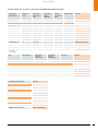
Contract variants and contents
SparesContract
Warranty
Extension
Maintenance
Contract
FullService
Contract
Benefits level
100
200
Spare parts availability over term of contract
9
9
300
100
100
100
9
9
9
9
Spare parts
--
Contractually assured delivery time for spare parts
--
9
9
9
--
9
--
3 WD1)
--
--
--
Routine maintenance: Maintenance parts
--
9
9
--
9
9
Routine maintenance: Engineer
--
--
--
--
9
9
Site service calls: Engineer
--
--
--
9
--
9
--
--
--
WD1)
Contractually assured response time for technical
support on site
--
--
3
Contractually assured response time for remote
support
--
--
--
--
--
1 WD1)
Assured repair time
--
--
--
--
--
3 WD1)
Telephone support 24/7
9
9
9
9
9
9
Reimbursement for loss of earnings
--
--
9
--
--
9
Agreed contract periods in years
15, 20
10, 15, 20
10, 15, 20
10, 20
10, 15, 20
10, 15, 20
9 yes
-- no
1)
WD = working day
Service & Support
29
© Siemens AG 2012
SINVERT PVS SparesContract –
Spares stocking as a low-cost alternative
spare part requirements. Any spare parts required shall be taken from the spares kit and replacement parts then ordered
free of charge from Siemens.
All repair and maintenance work shall be carried out by the
customer's own trained service personnel.
In the event that on-site troubleshooting support by a
Siemens specialist is required, a service call must be ordered
separately.
SINVERT PVS WarrantyExtension –
Extends the period of the standard warranty
SINVERT PVS SparesContract
For large-scale photovoltaic plants operated by customers
who employ their own on-site maintenance personnel, it
might make more sense economically to conclude a spares
contract which would assure availability of spare parts over
the entire contract term.
Three benefits levels
SINVERT PVS Spares Contracts are available with three
benefits levels (100, 200 and 300) and with contract terms
of 10, 15 or 20 years to suit the individual requirements of the
customer (a contract term of 15 or 20 years must be selected
in combination with benefits level 100).
■
The following applies to all three benefits levels:
– Assured availability of spare parts over the entire
term of the contract
– A 24-hour hotline has been set up to provide technical
support by our Technical Assistance team and to
arrange service calls. Troubleshooting support by
means of remote access will be offered where
necessary.
■
Additional services with benefits levels 200 and 300:
– All spares and routine maintenance parts which are
needed on site over the contract term shall be
provided free of charge by Siemens.
– Siemens will supply the required parts free of charge
on receipt of notification that routine maintenance is
due.
■
Additional services with benefits level 300:
– Contractually assured spare parts delivery time of 3
working days
– Contractually assured response time of 3 working
days for provision of on-site support by a Siemens
engineer
– Reimbursement of loss of earnings in the event that
Siemens cannot respond within the assured times.
A basic condition for conclusion of a SINVERT PVS SparesContract
is that the customer purchases a spares kit to cover initial
30
Service & Support
SINVERT PVS WarrantyExtension service contract
The SINVERT PVS WarrantyExtension option can be selected
as a quick and simple means of extending the standard
5-year manufacturer warranty for the SINVERT PVS inverters.
The customer can choose to extend the warranty to 10 or 20
years depending on individual requirements.
This service contract is intended for customers who wish to
call on support from Siemens specialists when servicing is
required.
The SINVERT PVS WarrantyExtension offers:
■
Spare parts
– The availability of spare parts is assured over the
entire contract term.
– All spare parts which are needed to repair defects
during service calls over the contract term shall be
provided free of charge by Siemens.
■
Telephone support
– A 24-hour hotline has been set up to provide technical
support by our Technical Assistance team and to
arrange service calls.
■
Field support
– After Siemens has received a fault notification,
Siemens specialists will rectify the fault via remote
access or will dispatch service personnel free of
charge to the site in question if this is deemed
necessary.
© Siemens AG 2012
SINVERT PVS MaintenanceContract –
Routine maintenance by Siemens
The SINVERT PVS FullServiceContract can be selected with a
contract term of 10, 15 or 20 years depending on the individual
requirements of the customer.
SINVERT PVS MaintenanceContract
SINVERT PVS FullServiceContract
The SINVERT PVS MaintenanceContract ensures that routine
maintenance is provided by Siemens specialists. This service
contract is intended for customers who want to use preventive
maintenance by Siemens specialists as a means of ensuring
that their plant remains fully functional at all times.
The SINVERT PVS FullServiceContract offers:
■
Spare parts
– The availability of spare parts is assured over the
entire contract term.
– All routine maintenance parts required to carry out all
the prescribed routine maintenance as well as any
spare parts needed to repair defects during service
callouts will be supplied free of charge by Siemens
over the term of the contract.
The SINVERT PVS MaintenanceContract can be selected with a
contract term of 10, 15 or 20 years depending on the individual
requirements of the customer.
The SINVERT PVS MaintenanceContract offers:
■
Spare parts
– The availability of spare parts is assured over the
entire contract term.
– All spare parts required to perform routine maintenance at the prescribed routine maintenance intervals over the term of the contract will be provided
free of charge by Siemens.
■
Telephone support
– A 24-hour hotline has been set up to provide technical
support by our Technical Assistance team and to
arrange service calls.
– A response time of one working day for providing
troubleshooting support via hotline/remote access is
guaranteed.
■
Telephone support
– A 24-hour hotline has been set up to provide technical
support by our Technical Assistance team and to
arrange service calls. Troubleshooting support by
means of remote access will be offered where
necessary.
■
On-site service
– Siemens shall bear all the costs of service engineer
callouts to site required to carry out the prescribed
routine maintenance or to eliminate faults during the
term of the contract.
■
■
Field support
– Siemens shall bear all the costs of service engineer
callouts to site required to carry out the prescribed
routine maintenance during the term of the contract.
The SINVERT PVS FullServiceContract ensures the
following in particular:
– The inverter shall be repaired within three working
days of receipt of notification of a fault from the
customer
– Any loss of earnings shall be reimbursed in the event
that Siemens cannot respond within the guaranteed
times
SINVERT PVS FullServiceContract –
All-inclusive package for all-round service
The all-inclusive SINVERT PVS FullServiceContract is intended
for customers who rely on the support of Siemens specialists
in every case and who wish to enjoy the benefits of all-round
service for their plant.
A basic condition for conclusion of a SINVERT PVS Full Service
Contract is that the customer purchases a spares kit to cover
initial spare part requirements. Any spare parts required shall
be taken from the spares kit and replacement parts then o
rdered free of charge from Siemens.
Service & Support
31
© Siemens AG 2012
Get more information:
Technical Assistance
Phone: +49 (911) 895-5900
Fax:
+49 (911) 895-5907
E-mail: [email protected]
Siemens AG
Industry Sector
Control Components and
Systems Engineering
Postfach 2355
90713 FÜRTH
GERMANY
www.siemens.com/sinvert
Subject to change without notice
Order No.: E86060-T1818-A101-A2-7600
MP.R3.XT.0000.00.2.07 / Dispo 46371
BR 0512 3. WÜ 32 En
Printed in Germany
© Siemens AG 2012
The information provided in this brochure contains descriptions
or characteristics of performance which in case of actual use do
not always apply as described or which may change as a result
of further development of the products. An obligation to provide
the respective characteristics shall only exist if expressly agreed
in the terms of contract. Availability and technical specifications
are subject to change without notice.
All product designations may be trademarks or product names
of Siemens AG or supplier companies whose use by third
parties for their own purposes could violate the rights of
the owners.