1
PVS 600Series
1
___________________
Introduction
2
___________________
Safety instructions
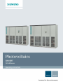
SINVERT inverter
Central inverter
PVS 600Series
Operating Instructions
3
___________________
Description
4
___________________
Grid management
___________________
5
Application planning
___________________
6
Installation
___________________
7
Connecting
___________________
8
Commissioning
Operator control and
___________________
9
monitoring
Fault, alarm and system
___________________
10
messages
___________________
11
Maintenance
___________________
12
Technical data
___________________
13
Dimension drawings
___________________
14
Ordering data
___________________
A
Technical support
Overview of master slave
___________________
B
cabling
08/2014
A5E03467293-003
Legal information
Warning notice system
This manual contains notices you have to observe in order to ensure your personal safety, as well as to prevent
damage to property. The notices referring to your personal safety are highlighted in the manual by a safety alert
symbol, notices referring only to property damage have no safety alert symbol. These notices shown below are
graded according to the degree of danger.
DANGER
indicates that death or severe personal injury will result if proper precautions are not taken.
WARNING
indicates that death or severe personal injury may result if proper precautions are not taken.
CAUTION
indicates that minor personal injury can result if proper precautions are not taken.
NOTICE
indicates that property damage can result if proper precautions are not taken.
If more than one degree of danger is present, the warning notice representing the highest degree of danger will
be used. A notice warning of injury to persons with a safety alert symbol may also include a warning relating to
property damage.
Qualified Personnel
The product/system described in this documentation may be operated only by personnel qualified for the specific
task in accordance with the relevant documentation, in particular its warning notices and safety instructions.
Qualified personnel are those who, based on their training and experience, are capable of identifying risks and
avoiding potential hazards when working with these products/systems.
Proper use of Siemens products
Note the following:
WARNING
Siemens products may only be used for the applications described in the catalog and in the relevant technical
documentation. If products and components from other manufacturers are used, these must be recommended
or approved by Siemens. Proper transport, storage, installation, assembly, commissioning, operation and
maintenance are required to ensure that the products operate safely and without any problems. The permissible
ambient conditions must be complied with. The information in the relevant documentation must be observed.
Trademarks
All names identified by ® are registered trademarks of Siemens AG. The remaining trademarks in this publication
may be trademarks whose use by third parties for their own purposes could violate the rights of the owner.
Disclaimer of Liability
We have reviewed the contents of this publication to ensure consistency with the hardware and software
described. Since variance cannot be precluded entirely, we cannot guarantee full consistency. However, the
information in this publication is reviewed regularly and any necessary corrections are included in subsequent
editions.
Siemens AG
Industry Sector
Postfach 48 48
90026 NÜRNBERG
GERMANY
A5E03467293-003
Ⓟ 08/2014 Subject to change
Copyright © Siemens AG 2010.
All rights reserved
Table of contents
1
2
3
4
Introduction ............................................................................................................................................. 9
1.1
Preface ...................................................................................................................................... 9
1.2
Recycling and disposal ...........................................................................................................10
Safety instructions ................................................................................................................................. 11
2.1
General safety instructions .....................................................................................................11
2.2
Health and safety at work .......................................................................................................13
2.3
Hazards during handling and installation ................................................................................14
2.4
Hazards in photovoltaic plants ................................................................................................14
2.5
Incorrect grid monitoring parameters ......................................................................................15
2.6
Possible safety gaps in the case of standard IT interfaces ....................................................15
2.7
Security information ................................................................................................................16
Description ............................................................................................................................................ 17
3.1
Features ..................................................................................................................................18
3.2
Design .....................................................................................................................................19
3.3
Operating principle ..................................................................................................................21
3.4
Master-slave combinations .....................................................................................................22
3.5
3.5.1
3.5.2
3.5.3
3.5.4
Inverter options .......................................................................................................................28
PV array grounding .................................................................................................................29
Increase in max. DC voltage to 1000 V ..................................................................................30
Cabinet heating .......................................................................................................................31
Symmetry monitoring ..............................................................................................................31
3.6
System components ...............................................................................................................32
Grid management ................................................................................................................................. 35
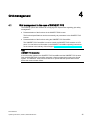
4.1
Grid management in the case of SINVERT PVS ....................................................................35
4.2
4.2.1
4.2.1.1
4.2.1.2
4.2.1.3
4.2.1.4
4.2.2
4.2.2.1
4.2.2.2
4.2.2.3
4.2.2.4
4.2.2.5
Static grid support ...................................................................................................................38
Active power control................................................................................................................38
Active power control to fixed setpoint .....................................................................................39
Active power control according to frequency P=f(f) ................................................................40
Active power control in accordance with output voltage P = f(U) ...........................................45
Active power control during the switch-on operation ..............................................................46
Reactive power control ...........................................................................................................48
Reactive power control to fixed setpoint Q absolute ..............................................................51
Reactive power control to fixed setpoint Q relative ................................................................52
Reactive power control to fixed setpoint cos phi ....................................................................54
Reactive power control according to time of day Q(t) .............................................................55
Reactive power control by means of cos φ (t) according to time of day .................................57
PVS 600Series
Operating Instructions, 08/2014, A5E03467293-003
5
Table of contents
5
6
7
4.2.2.6
4.2.2.7
Reactive power control in accordance with output voltage Q=f(U) ........................................ 59
Reactive power control according to active power cos φ (P)................................................. 62
4.3
4.3.1
4.3.2
4.3.3
4.3.4
4.3.5
4.3.6
Dynamic grid support ............................................................................................................. 64
Behavior in the case of voltage dips (low voltage ride through) ............................................ 64
Shutdown behavior in the event of voltage dips .................................................................... 64
Reactive current provision in the event of voltage dips ......................................................... 67
Behavior in the case of voltage rises (low voltage ride through) ........................................... 69
Shutdown behavior in the event of voltage rises ................................................................... 69
Reactive current provision in the event of voltage rises ........................................................ 72
4.4
4.4.1
4.4.2
4.4.3
4.4.4
Decoupling protection ............................................................................................................ 74
Grid monitoring....................................................................................................................... 74
Frequency monitoring ............................................................................................................ 74
Voltage monitoring ................................................................................................................. 76
Feed-in conditions .................................................................................................................. 79
Application planning .............................................................................................................................. 81
5.1
5.1.1
5.1.2
5.1.3
5.1.4
5.1.5
Packaging, dispatch and delivery .......................................................................................... 81
Transport packaging .............................................................................................................. 81
Center of gravity marking and transport position ................................................................... 83
Dispatch and delivery ............................................................................................................. 83
Checking the consignment ..................................................................................................... 83
Scope of supply...................................................................................................................... 84
5.2
5.2.1
5.2.2
5.2.3
5.2.3.1
5.2.3.2
5.2.3.3
5.2.4
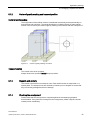
Transport ................................................................................................................................ 84
General safety instructions for transporting ........................................................................... 84
Transporting using pallet truck and fork-lift truck ................................................................... 88
Transporting by crane ............................................................................................................ 89
General notices ...................................................................................................................... 89
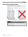
Permissible transport methods .............................................................................................. 90
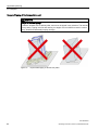
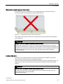
Impermissible transport methods ........................................................................................... 92
Transport and alignment of cabinets in electrical operating areas ........................................ 93
5.3
Storage ................................................................................................................................... 95
5.4
5.4.1
5.4.2
5.4.3
5.4.4
Site of installation ................................................................................................................... 96
General requirements ............................................................................................................ 96
Requirements of electrical operating areas ........................................................................... 97
Ventilation (air supply and extraction) .................................................................................... 99
Grounding and lightning protection ........................................................................................ 99
5.5
Configuring information ........................................................................................................ 100
Installation ...........................................................................................................................................101
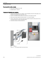
6.1
Preparation........................................................................................................................... 101
6.2
Safety information on bolting the cabinet sections together ................................................ 102
6.3
Bolting the cabinet sections together ................................................................................... 103
6.4
Mechanical connection to the foundation ............................................................................ 104
6.5
Installing the exhaust-air shrouds (optional) ........................................................................ 105
Connecting ..........................................................................................................................................107
7.1
Universal safety instructions ................................................................................................ 107
PVS 600Series
6
Operating Instructions, 08/2014, A5E03467293-003
Table of contents
8
9
10
7.2
Cabling ..................................................................................................................................109
7.3
7.3.1
7.3.2
7.3.3
7.3.4
7.3.5
7.3.6
7.3.7
7.3.8
7.3.9
7.3.10
7.3.11
Connecting the individual cables ..........................................................................................110
Requirements ........................................................................................................................110
Overview ...............................................................................................................................110
Grounding .............................................................................................................................112
Signal cables and internal communication ...........................................................................113
Connection for the option "PV array grounding" ...................................................................118
External communication........................................................................................................119
Connection between DC and AC cabinet .............................................................................120
AC auxiliary power supply ....................................................................................................121
Main AC grid .........................................................................................................................122
DC link (only for master-slave combinations) .......................................................................123
DC input ................................................................................................................................124
7.4
Rapid stop function ...............................................................................................................125
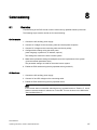
Commissioning ................................................................................................................................... 127
8.1
Overview ...............................................................................................................................127
8.2
Commissioning the inverter ..................................................................................................128
8.3
Parameterizing the inverter ...................................................................................................133
8.4
8.4.1
8.4.2
Decommissioning the inverter ..............................................................................................134
Decommissioning an inverter subunit ...................................................................................134
Decommissioning the entire inverter ....................................................................................134
Operator control and monitoring .......................................................................................................... 137
9.1
Operation states ....................................................................................................................137
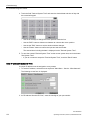
9.2
Parameters ...........................................................................................................................138
9.3
Controlling the inverter via the operator panel ......................................................................139
9.4
9.4.1
9.4.2
9.4.3
9.4.4
9.4.5
9.4.6
Operating and monitoring the inverter via the touch panel ...................................................141
Introduction ...........................................................................................................................141
Navigation structure of the touch panel ................................................................................141
Start window (status indicator) ..............................................................................................142
Main menu ............................................................................................................................143
General information on working with the tool .......................................................................145
Service ..................................................................................................................................145
9.5
9.5.1
9.5.2
9.5.3
9.5.4
9.5.5
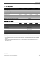
Parameter list ........................................................................................................................146
Introduction ...........................................................................................................................146
DC settings ...........................................................................................................................147
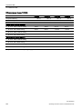
Grid parameters ....................................................................................................................148
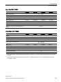
Temperatures and times .......................................................................................................149
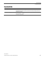
Miscellaneous .......................................................................................................................151
9.6
Rapid stop function ...............................................................................................................152
Fault, alarm and system messages ..................................................................................................... 153
10.1
Fault messages .....................................................................................................................153
10.2
Fault correction .....................................................................................................................155
10.3
Alarms ...................................................................................................................................166
PVS 600Series
Operating Instructions, 08/2014, A5E03467293-003
7
Table of contents
11
12
13
14
10.4
Correction of the alarms ....................................................................................................... 167
10.5
Event messages................................................................................................................... 170
10.6
Messages of the operator panel .......................................................................................... 178
Maintenance ........................................................................................................................................179
11.1
Servicing .............................................................................................................................. 179
11.2
Maintenance......................................................................................................................... 179
11.3
Cleaning the inside of the cabinet ........................................................................................ 180
11.4
Replacing the reactor fan ..................................................................................................... 181
11.5
Replacing the fan of the inverter module (ALM) .................................................................. 181
Technical data .....................................................................................................................................185
12.1
Environmental conditions ..................................................................................................... 185
12.2
Mechanical data ................................................................................................................... 186
12.3
Electrical data....................................................................................................................... 187
12.4
Operator panel and interfaces ............................................................................................. 198
12.5
Applicable standards and conformity ................................................................................... 198
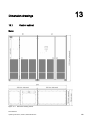
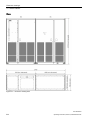
Dimension drawings .............................................................................................................................199
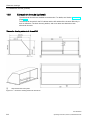
13.1
Control cabinet ..................................................................................................................... 199
13.2
Base plate ............................................................................................................................ 201
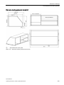
13.3
Exhaust-air shrouds (optional) ............................................................................................. 202
Ordering data .......................................................................................................................................205
14.1
SINVERT PVS inverters ...................................................................................................... 205
14.2
Options ................................................................................................................................. 207
14.3
Accessories .......................................................................................................................... 208
A
Technical support.................................................................................................................................209
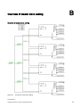
B
Overview of master slave cabling .........................................................................................................211
Index ...................................................................................................................................................213
PVS 600Series
8
Operating Instructions, 08/2014, A5E03467293-003
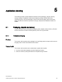
Introduction
1.1
1
Preface
Purpose of the manual
These operating instructions contain all the information required for installing,
commissioning, and operating PVS 600Series inverters.
This manual is aimed at qualified personnel in the following target groups:
● Planners
● Installation personnel
● Commissioning engineers
● Service and maintenance personnel
● Operators
Validity of the documentation
The operating instructions apply to the inverters
● SINVERT PVS500, SINVERT PVS1000, SINVERT PVS1500 and SINVERT PVS2000
with frequencies of 50 Hz and 60 Hz.
● SINVERT PVS585, SINVERT PVS1170, SINVERT PVS1755 and SINVERT PVS2340
with frequencies of 50 Hz and 60 Hz.
● SINVERT PVS600, SINVERT PVS1200, SINVERT PVS1800 and SINVERT PVS2400
with frequencies of 50 Hz and 60 Hz.
● SINVERT PVS630, SINVERT PVS1260, SINVERT PVS1890 and SINVERT PVS2520
with frequencies of 50 Hz and 60 Hz.
Conventions
Within this manual, the shortened name SINVERT PVS is used in addition to the full product
name when referring to inverters.
Photovoltaic system is shortened to PV system.
Trademarks
SINVERT® is a registered trademark of Siemens AG.
PVS 600Series
Operating Instructions, 08/2014, A5E03467293-003
9
Introduction
1.2 Recycling and disposal
1.2
Recycling and disposal
Devices described in this programming manual can be recycled owing to the low content of
noxious substances in their version. Please contact a certified waste disposal company for
eco-friendly recycling and to dispose of your old devices.
PVS 600Series
10
Operating Instructions, 08/2014, A5E03467293-003
Safety instructions
2.1
2
General safety instructions
Note
Please observe the legal information and the safety instructions on the back of the cover
sheet of this documentation.
Qualified personnel
Installation, commissioning, operation and maintenance of this device must be carried out by
qualified personnel only.
● The installation engineer must be qualified according to national guidelines.
● Approval by the relevant electrical utility may also be necessary.
Intended use
To ensure the greatest possible degree of system safety, it is absolutely essential that the
product is used for its intended purpose.
The SINVERT inverter and its variants are designed solely for the purpose of converting the
energy generated by PV modules from a DC current into an AC current and of feeding this
AC current into a medium-voltage grid. Compliance with all specifications regarding
permissible conditions of use as outlined in these operating instructions is essential. To
satisfy this requirement, it is essential that these operating instructions are read in full by the
qualified personnel responsible for the system and that all instructions are followed.
In addition, the conditions specified by the PV module manufacturer and grid operator must
be fulfilled. The products may be modified only with the agreement of the manufacturer.
It is not permissible to commission the system unless all requirements are satisfied in full.
Any usage other than that described in this chapter is deemed to be improper usage.
Siemens disclaims liability for any damage attributable to improper usage.
Use of approved equipment and components
Always use the equipment and components described and approved by the manufacturer for
the intended purpose. The manufacturer disclaims liability for any damage arising from the
use of equipment or components which are not approved for the intended purpose.
PVS 600Series
Operating Instructions, 08/2014, A5E03467293-003
11
Safety instructions
2.1 General safety instructions
Modifications to the product
Modifications to the SINVERT inverter may be made only if these have been explicitly
approved by the system manufacturer. The manufacturer shall not be liable for any damage
arising from unapproved modifications to the SINVERT inverter.
Repairs
Only authorized personnel are permitted to repair the device.
Electrical voltages
The PVS cabinets must be opened and worked on by qualified personnel only.
WARNING
Hazardous electrical voltages at the opened cabinet
Even if the device is switched off, life-threatening voltage may be present inside the
cabinet.
Consequently, only qualified expert personnel must work at the open cabinet in compliance
with the safety rules.
PVS 600Series
12
Operating Instructions, 08/2014, A5E03467293-003
Safety instructions
2.2 Health and safety at work
2.2
Health and safety at work
It is essential that you adhere to the health and safety regulations, e.g. VDE 105-1/EN
50110-1 (Operation of Electrical Installations), which apply at the relevant installation site.
Protective gear and equipment
Qualified personnel must always carry the protective gear, tools and accessories listed
below and use them in the prescribed manner:
● Insulating footwear, gloves and shoe covers
● Goggles and protective face masks
● Protective headwear
● Appropriate protective clothing
● Ear protection
● Insulating cover materials, flexible or rigid
● Insulated tools and tools made of insulation material
● Locks, labels and notices, signs
● Voltage testers and test systems
● Grounding / short-circuiting devices and fixtures
● Materials for barrier erection, flagging and signing.
Following EN 50110-1 all tools, items of equipment, protective gear and other accessories
must be suitable for the intended purpose and in good condition. They must be used for the
prescribed purpose and stored properly.
Precautionary measures for increasing safety
Follow all instructions and safety notices. Never work alone on the unit. In the event of an
accident, a second person must be capable of administering first aid immediately.
WARNING
Risk to life; serious physical injury, substantial damage to equipment! Hazardous voltages
and currents!
All work must be carried out by qualified personnel. Follow all instructions relating to health
and safety at work. Failure to adhere to safety procedures could result in death, serious
physical injury and/or substantial property damage.
PVS 600Series
Operating Instructions, 08/2014, A5E03467293-003
13
Safety instructions
2.3 Hazards during handling and installation
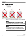
2.3
Hazards during handling and installation
Improper handling and installation of certain parts and components can result in injury under
unfavorable conditions.
CAUTION
Danger of injury due to improper handling! Injury by crushing, jackknifing, cutting, bumping,
or lifting!
• The general construction and safety regulations must be observed in handling and
installation.
• Each cabinet section weighs more than 1,000 kg.
• Suitable installation and transport equipment must be used. Read the specifications and
safety information of the chapter Application planning (Page 81).
• Only use suitable tools.
• Lifting equipment and tools must be used correctly.
• Suitable protective equipment (e.g. safety goggles, safety shoes, protective gloves)
must be used.
• Never stand underneath suspended loads.
2.4
Hazards in photovoltaic plants
Below are listed some typical special features and hazard sources in photovoltaic plants:
● Since the short-circuit current only slightly exceeds the maximum operating current, there
is no clear guarantee that the available fuse will trip in the event of a short-circuit.
● Depending on the operating status, the plant can still be under power from the PV
generator via the SINVERT PVS inverter even when it is switched off. This must be
remembered when isolating the plant or sections of the plant.
● The PV generator is usually configured as an IT system without grounded transformer. A
ground fault generates a fault message. In an IT system, there is no immediate danger of
electric shock if no further fault occurs. Despite this, the ground fault must be corrected
as quickly as possible by qualified personnel.
PVS 600Series
14
Operating Instructions, 08/2014, A5E03467293-003
Safety instructions
2.5 Incorrect grid monitoring parameters
2.5
Incorrect grid monitoring parameters
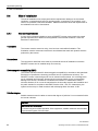
NOTICE
Withdrawal of operating permit
If you operate the SINVERT PVS inverter with the wrong grid monitoring parameters, the
electrical utility can withdraw your operating permit.
The device must therefore only be commissioned by authorized service personnel. The
system settings must be adapted to local requirements regarding grid monitoring
parameters.
We assume no responsibility for incorrect grid monitoring parameters.
2.6
Possible safety gaps in the case of standard IT interfaces
In SINVERT inverters, extensive parameterization and diagnostics functions are provided via
open protocols and interfaces (e.g. Web server, network management). The possibility of
unauthorized misuse of these open protocols and interfaces by third parties, for example to
manipulate data, cannot be entirely excluded.
When using the functions listed above and these open interfaces and protocols (for example,
SNMP, OPC, HTTP), you should take suitable security measures to prevent unauthorized
access to the components and the network, particularly from within the WAN/Internet.
NOTICE
We expressly point out that the inverter network must be isolated from the rest of the
company network by suitable gateways (for example, field-proven firewall systems). We do
not accept any liability whatsoever, whatever the legal justification, for damage resulting
from non-adherence to this notice.
If you have questions on the use of firewall systems and IT security, please contact your
local Siemens office or representative.
PVS 600Series
Operating Instructions, 08/2014, A5E03467293-003
15
Safety instructions
2.7 Security information
2.7
Security information
Siemens provides products and solutions with industrial security functions that support the
secure operation of plants, solutions, machines, equipment and/or networks. They are
important components in a holistic industrial security concept. With this in mind, Siemens’
products and solutions undergo continuous development. Siemens recommends strongly
that you regularly check for product updates.
For the secure operation of Siemens products and solutions, it is necessary to take suitable
preventive action (e.g. cell protection concept) and integrate each component into a holistic,
state-of-the-art industrial security concept. Third-party products that may be in use should
also be considered. For more information about industrial security, visit
http://www.siemens.com/industrialsecurity.
To stay informed about product updates as they occur, sign up for a product-specific
newsletter. For more information, visit http://support.automation.siemens.com.
PVS 600Series
16
Operating Instructions, 08/2014, A5E03467293-003
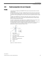
Description
3
The inverter of the SINVERT PVS device line is used in medium and large PV plants and
converts the DC current of the PV generators into AC current. This AC current is then fed
into the connected power grid. The SINVERT PVS inverter design is optimized for the lowest
possible losses and thus the greatest possible efficiency.
Figure 3-1
Installation overview
The integrated DC and AC distribution makes the system compact and cheap to integrate.
The system is provided with standardized interfaces so that it can be integrated into a control
system or an existing customer installation.
PVS 600Series
Operating Instructions, 08/2014, A5E03467293-003
17
Description
3.1 Features
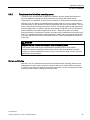
3.1
Features
SINVERT PVS is a three-phase inverter with the following features:
● Standardized series product with CE mark
● Compliance with international standards: DIN VDE, IEC, EN
● QS system is certified in accordance with DIN EN ISO 9001
● Optimized for high efficiency
● Self-commutated, pulse-width-modulated (PWM) IGBT inverter
● Compact design, very easy to install
● Integrated DC connection including insulation monitor, contactors and semiconductor
fuses
● Integrated AC connection with line monitor, line contactor and circuit breaker
● Terminal compartment with separate panels for DC and AC terminal connections
● Overvoltage protection on DC and AC sides
● Operation on AC systems with 50 or 60 Hz
● Enclosed base plate with bushing for connecting cables
● Bus communication via Industrial Ethernet for integration into operations management
systems
● Operator control and monitoring elements integrated into cabinet door
● Delivery on special pallets
● Air inlet through ventilation grille at front, air exit at top
● Heat dissipated by low-noise fan
● All cabinet components can be recycled
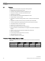
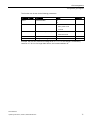
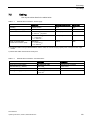
PVS versions PVS500, PVS585, PVS600 and PVS630
The most important differences between the PVS versions can be seen from the technical
data below:
PVS500
PVS585
PVS600
PVS630
AC output voltage
288 V
340 V
370 V
370 V
Active power generated
500 kW
585 kW
600 kW
630 kW
MPP window
450 … 750 V
530 … 750 V
570 … 750 V
570 … 750 V
PVS 600Series
18
Operating Instructions, 08/2014, A5E03467293-003
Description
3.2 Design
3.2
Design
Inverter subunit and inverter unit
An inverter subunit always consists of a DC cabinet and an AC cabinet.
A complete inverter unit can comprise up to 4 inverter subunits (DC/AC cabinets) that are
also referred to as master-slave combinations (see Chapter Master-slave combinations
(Page 22)).
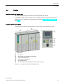
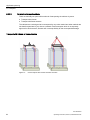
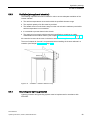
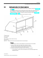
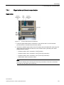
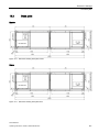
Design of an inverter subunit
The figure below shows the design principle of the inverter subunit with closed doors:
①
②
③
④
⑤
⑥
⑦
DC cabinet
AC cabinet
Touch panel (only available on master unit)
Green indicator light "Run"
Yellow indicator light "Fault"
Key-operated switch
Service interface: Industrial Ethernet (for the master unit only)
Figure 3-2
Design of the inverter subunit (master unit)
PVS 600Series
Operating Instructions, 08/2014, A5E03467293-003
19
Description
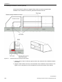
3.2 Design
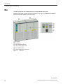
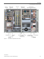
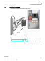
The figure below shows the higher-level function units of the inverter subunit with open
doors.
①
②
③
④
⑤
⑥
⑦
⑧
⑨
⑩
⑪
⑫
Modules for 1000V option
Modules for PV field grounding option
Modules for options
DC contactors
DC terminal compartment of the PV field and LV HRC fuses
Inverter module (power unit)
Connection to AC cabinet
Communication area
AC filter
Cooling ventilators, reactors, connection to DC cabinet
AC contactor
AC terminal compartment, circuit breaker for isolating the AC system and overvoltage protection
Figure 3-3
Function units of the inverter subunit
PVS 600Series
20
Operating Instructions, 08/2014, A5E03467293-003
Description
3.3 Operating principle
3.3
Operating principle
The SINVERT PVS inverter works on the following functional principles:
● The inverters are based on SINAMICS (power unit with IGBT three-phase bridge) and
SIMOTION (controller).
● 3 inputs for connecting the PV array are provided at the PV array end.
Note
The PV array must be connected for this purpose in 3 sub-arrays with the same total
current and voltage values.
● The 3 inputs on the DC side are equipped with LV HRC fuses and DC contactors. This
combination can be used to disconnect the inverter from the PV side.
● AC filters are used to smooth the AC output voltage.
● The AC output must be connected directly to the medium-voltage transformer for galvanic
isolation. This is required at the AC output of every inverter subunit.
● A contactor and circuit breaker are used to disconnect the unit from the AC grid.
● Overvoltage protection devices are installed on the AC and DC sides.
● To increase efficiency and reduce no-load losses, up to four inverters can be
interconnected in master/slave operation.
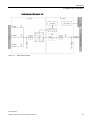
Block diagram of the SINVERT PVS 600 Series
Figure 3-4
Block diagram of the SINVERT PVS 600Series inverter (master version)
PVS 600Series
Operating Instructions, 08/2014, A5E03467293-003
21
Description
3.4 Master-slave combinations
3.4
Master-slave combinations
A SINVERT PVS inverter subunit is available in two versions:
● Master
● Slave
The combination of a master unit and one or more slave unit(s) results in a master/slave
combination.
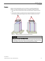
Master
The master comprises a DC cabinet and an AC cabinet with touch panel.
A master with a touch panel is required in every configuration. The master or the entire
installation can be operated and monitored via the touch panel.
The SINVERT PVS500, PVS585, PVS600 and PVS630 consist exclusively of one master.
①
②
③
④
⑤
⑥
⑦
DC cabinet
AC cabinet
Touch panel
Green indicator light "Run"
Yellow indicator light "Fault"
Key-operated switch
Service interface: Industrial Ethernet
Figure 3-5
Master unit
PVS 600Series
22
Operating Instructions, 08/2014, A5E03467293-003
Description
3.4 Master-slave combinations
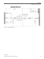
Block diagram of the master unit
Figure 3-6
Block diagram master
PVS 600Series
Operating Instructions, 08/2014, A5E03467293-003
23
Description
3.4 Master-slave combinations
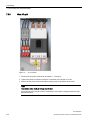
Slave
The slave comprises a DC cabinet and an AC cabinet without touch panel.
Since the slave does not have its own touch panel, it can only be operated and monitored
using an associated master or its touch panel.
①
②
③
④
⑤
⑥
DC cabinet
AC cabinet
Green indicator light "Run"
Yellow indicator light "Fault"
Key-operated switch
Service interface (not functional)
Figure 3-7
Slave unit
PVS 600Series
24
Operating Instructions, 08/2014, A5E03467293-003
Description
3.4 Master-slave combinations
Block diagram of the slave unit
Figure 3-8
Block diagram slave
PVS 600Series
Operating Instructions, 08/2014, A5E03467293-003
25
Description
3.4 Master-slave combinations
Master/slave combinations
The inverters of the SINVERT PVS500, PVS585, PVS600 or PVS630 series can be used as
single devices or in combination with other inverter subunits in a master/slave combination.
Such a combination always has a master and can additionally contain up to three slaves.
The following master/slave combinations are available.
SINVERT
PVS500 series
SINVERT
PVS585 series
SINVERT
PVS600 series
SINVERT
PVS630 series
Design
SINVERT PVS500
SINVERT PVS585
SINVERT PVS600
SINVERT PVS630
1 x master (with touch panel on
the AC cabinet)
SINVERT PVS1000
SINVERT PVS1170 SINVERT PVS1200 SINVERT PVS1260
1 x master (with touch panel on
the AC cabinet)
1 x slave
SINVERT PVS1500
SINVERT PVS1755 SINVERT PVS1800 SINVERT PVS1890
1 x master (with touch panel on
the AC cabinet)
2 x slave
SINVERT PVS2000
SINVERT PVS2340 SINVERT PVS2400 SINVERT PVS2520
1 x master (with touch panel on
the AC cabinet)
3 x slave
Block diagram of the master/slave combination SINVERT PVS2000 / PVS2340 / PVS2400 / PVS2520
The block diagram of the maximum configuration provides an example of the additional
interconnection of the inverter subunits by the DC link.
Note
Each subunit of an inverter must be connected to the medium-voltage transformer with
galvanic isolation.
PVS 600Series
26
Operating Instructions, 08/2014, A5E03467293-003
Description
3.4 Master-slave combinations
Figure 3-9
Block diagram of the master/slave combination SINVERT PVS2000 / PVS2340 / PVS2400 / PVS2520
PVS 600Series
Operating Instructions, 08/2014, A5E03467293-003
27
Description
3.5 Inverter options
3.5
Inverter options
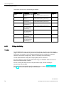
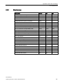
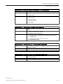
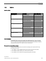
The following functional expansions and options are available for the PVS 600Series:
Option
Option identifier on the nameplate
PV array grounding - positive-pole grounding
PV field grounding positive pole
PV array grounding - negative-pole grounding
PV field grounding negative pole
Increase in max. DC voltage to 1 000 V
Max. UDC Betrieb 1000V
Symmetry monitoring
Symmetry monitoring
Cabinet heating
Cabinet heating
Option identifier on the nameplate
You can see from the nameplate which options your device is equipped with.
Figure 3-10
Example of a rating plate
PVS 600Series
28
Operating Instructions, 08/2014, A5E03467293-003
Description
3.5 Inverter options
3.5.1
PV array grounding
With the optional feature "Positive / Negative PV array Grounding", the SINVERT inverters
offer an ideal choice for manufacturers who require a module ground.
Remember: For the latest information about the necessity for and type of grounding, please
contact your module manufacturer!
Some module manufacturers recommend positive or negative grounding of the PV generator
when certain types of module are used!
PV systems no longer constitute a DC IT system when their modules are grounded. For
safety reasons, the PV system must be fenced in and designated as an electrical operating
area.
Access must be prohibited to all persons except qualified electricians.
Positive-pole grounding
Grounding an active conductor (positive pole) means that the inverter's insulation measuring
function no longer works in the normal way. A hazardous current can start to flow as soon as
the first insulation damage occurs. For this reason, the condition of the system is monitored
through measurement of the current between the positive pole and ground. If the current
level measured is deemed to pose a risk (current value is parameterizable), the connection
is automatically broken by means of a motor-operated DC disconnector. This DC
disconnector is driven by the inverter's control system. In this context, it is important to note
that the connection between the module array and inverter ground must be of high quality. If
the connection resistance is high as a result of very dry conditions or unfavorable ground
conditions, a sufficiently high current will not flow. It is also important to note that a fault at
the same potential when grounded will not drive a current.
The DC disconnector has three settings:
● Remote triggering
● Local operation
● "Off signal" position, lockable
PVS 600Series
Operating Instructions, 08/2014, A5E03467293-003
29
Description
3.5 Inverter options
Negative-pole grounding
Grounding an active conductor (negative pole) means that the inverter's insulation
measuring function no longer works in the normal way. A hazardous current can start to flow
as soon as the first insulation damage occurs. For this reason, the condition of the system is
monitored through measurement of the current between the negative pole and ground. If the
current level measured is deemed to pose a risk (current value is parameterizable), the
connection is automatically broken by means of a motor-operated DC disconnector. The
disconnector is driven by the inverter's control system. In this context, it is important to note
that the connection between the module array and inverter ground must be of high quality. If
the connection resistance is high as a result of very dry conditions or unfavorable ground
conditions, a sufficiently high current will not flow. It is also important to note that a fault at
the same potential when grounded will not drive a current.
The DC disconnector has three settings:
● Remote triggering
● Local operation
● "Off signal" position, lockable
3.5.2
Increase in max. DC voltage to 1000 V
Areas of application and use
The "1000 V option" increases the maximum DC no-load voltage for inverters to DC 1000 V.
This ensures that the photovoltaic system can also operate with a (no-load) voltage of up to
DC 1000 V, for example when operating on cold days. The profitability of the equipment is
maximized as more modules can be connected in series, without affecting the ability of the
PVS inverter to switch on.
When will the equipment operate at no load?
No-load operation will happen at the following times:
● Before switching on the PV inverter
● After switching off the PV inverter
Standard response of the PVS inverter without the "1000 V option"
The PV inverters of the PVS series feature a switch-on voltage of max. 820 V DC as
standard. If the DC voltage is above 820 V, the SINVERT PVS PV inverter will not switch on.
The 1000 V option allows the switching on and off of the SINVERT PVS PV inverter for PV
field no-load voltages of up to 1000 V DC.
PVS 600Series
30
Operating Instructions, 08/2014, A5E03467293-003
Description
3.5 Inverter options
Switching on the PV inverter with "1000 V option"
Switching on the PVS allows a variable voltage divider, consisting of series and parallel
resistors, to activate the inverter DC link (without closing the DC input contactors). Thus only
the required fraction of the PV field no-load voltage is present at the DC link, and not the
entire PV field no-load voltage. The upstream measurement of the PV field voltage (Upv) is
carried out in each individual inverter subunit. Only when the PVS SINAMICS power unit is
operating and the AC main contactor is closed do the DC power contactors close in
succession.
Switching off the PV inverter with "1000 V option"
When switching off the last (of max. four) PV inverter subunits in normal operation, the DC
power contactors are first opened in succession, before the SINAMICS power unit of the
inverter subunit is switched off and the AC contactor opened.
During normal operation this ensures that the PV field no-load voltage is not present at the
DC link.
Unintentional disconnection of the PV inverter with "1000 V option"
During operation of the PV inverter, situations may arise which lead to the PV inverter and
the power unit to be switched off unintentionally. In such cases it is not always possible to
successively or immediately switch off the DC power contactors prior to switching off the
power unit, or they are switched off too slowly, to prevent the DC link voltage rising to
impermissible values. In such cases, to protect the DC link against voltages which are too
high, the following components are used:
● 1000 V special chopper
● Chopper resistor
● Crowbar
3.5.3
Cabinet heating
Heating elements are integrated into the inverter to prevent condensation and if atmospheric
humidity is too high. These heating elements are controlled by a hygrostat.
3.5.4
Symmetry monitoring
The symmetry monitoring option measures the scaled currents within the inverter at the DC
inputs and compares the values with each other.
If this comparison indicates deviations over time, a message is generated. The message can
be used for early detection of faults in parts of the photovoltaic field (e.g. cell failure).
PVS 600Series
Operating Instructions, 08/2014, A5E03467293-003
31
Description
3.6 System components
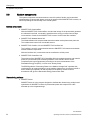
3.6
System components
The system components and accessories are used for optimal, flexible, and customized
implementation of photovoltaic plants covering all aspects of the SINVERT PVS inverters, as
well as expanding the functionality of the overall system.
System components
● SINVERT PVS CombinerBox
With the SINVERT PVS CombinerBox, the individual strings of the photovoltaic generator
are collected in the field, connected in parallel and the energy conveyed across large
cross-sections of cable to the SINVERT PVS inverter. Various sizes are available.
● SINVERT PVS WeatherStation 200
The WeatherStation 200 acquires data about the weather at the photovoltaic plant site.
This weather data comes from connected sensors.
● SINVERT PVS ComBox 100 and SINVERT PVS ComBox 200
The ComBox is used for communication between SINVERT PVS inverters and suitable
network-enabled components.
With the ComBox 200, inverter data can be transferred to a Web portal.
● SINVERT PVS ControlBox 300
The purpose of the SINVERT PVS ControlBox 300 is to regulate the active and reactive
power of a photovoltaic plant containing SINVERT PVS inverters and to ensure
compliance with legal requirements (according to the current amendment of the
Renewable Energy Act (EEG), in force since January 2009).
The BDEW guideline "Generating Plants in the Medium-Voltage Grid" stipulates this
requirement for all systems feeding in at the medium-voltage level. Its primary benefit is
that it enables grid operators to limit the output of the plant by remote control in
accordance with §6 of the Renewable Energy Sources Act 2009.
Dimensioning software
● SINVERT Select
SINVERT Select is a free program designed to facilitate the dimensioning, analysis and
optimization of SINVERT inverters for photovoltaic plants with outputs from a few
kilowatts up to the megawatt range.
PVS 600Series
32
Operating Instructions, 08/2014, A5E03467293-003
Description
3.6 System components
Monitoring and parameterization software
● SINVERT ConfigTool
SINVERT ConfigTool is a free software program designed for configuring,
parameterizing, and diagnosing inverters for photovoltaic installations.
● WinCC
With our WinCC SCADA system, we offer you user-friendly monitoring and control of your
entire photovoltaic plant.
Accessories
● Fan shrouds
Reference
For additional information, please refer to the associated operating instructions in the
Industry Online Support
(http://support.automation.siemens.com/WW/view/en/46183609/133300).
PVS 600Series
Operating Instructions, 08/2014, A5E03467293-003
33
Description
3.6 System components
PVS 600Series
34
Operating Instructions, 08/2014, A5E03467293-003
Grid management
4.1
4
Grid management in the case of SINVERT PVS
The following options are available for complying with requirements regarding grid safety
management:
● Parameterization of the functions in the SINVERT PVS inverter
The functions/specifications can be set manually via parameters in the SINVERT PVS
inverter.
● Parameterization of the functions using the SINVERT PVS ControlBox
The SINVERT PVS ControlBox is used to control the SINVERT PVS inverters of a PV
plant. You can find more information in the SINVERT ControlBox operating instructions
on the Internet in the Industry Online Support (http://support.automation.siemens.com).
Note
SINVERT PVS ControlBox
If communication between the SINVERT PVS ControlBox and the SINVERT PVS inverter
fails, the SINVERT PVS ControlBox generates a fault message that is sent to the Scada
system. The SINVERT PVS inverter continues to operate with the specifications it had
before the communication failure.
PVS 600Series
Operating Instructions, 08/2014, A5E03467293-003
35
Grid management
4.1 Grid management in the case of SINVERT PVS
Technical requirements of the inverter
The grid requirements are divided into static grid support, decoupling protection, and
dynamic grid support.
To meet the requirements of grid operators, you also require a plant controller such as a
SINVERT PVS ControlBox, in addition to the functions in the SINVERT PVS inverter.
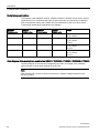
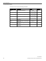
The following static grid support functions are fulfilled by SINVERT PVS:
Function
Inverter
ControlBox
Static grid support
Active power control
•
To fixed setpoint
✓
✓
•
According to frequency P = f(f)1)
✓
✓
•
According to output voltage P = f(U)
✓
-
•
Active power limitation during the switch-on operation
✓
-
•
By means of signals from the power utility
-
✓
Reactive power control
•
To absolute Q setpoint
✓
-
•
To relative Q setpoint
✓
✓
•
To absolute cos φ setpoint
✓
✓
•
According to time of day Q(t)2)
✓
✓
•
By means of cos φ (t) according to time of day2)
✓
✓
•
According to output voltage Q = f(U)2)
✓
✓
•
According to cos φ (P)2)
✓
✓
•
By means of signals from the power utility
-
✓
Frequency monitoring
✓
-
Voltage monitoring
✓
-
Feed-in conditions
✓
-
Low voltage ride through (LVRT)
✓
-
High voltage ride through (HVRT)
✓
-
Fault ride through (FRT)
✓
-
Decoupling protection
Dynamic grid support
1)
The function must only be activated either in the inverter or in the ControlBox.
2)
If a ControlBox is used, the function must be deactivated in the inverter.
PVS 600Series
36
Operating Instructions, 08/2014, A5E03467293-003
Grid management
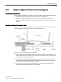
4.1 Grid management in the case of SINVERT PVS
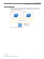
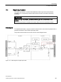
Interface to the grid operator
Communication with the grid operator is achieved via a SINVERT PVS ControlBox. The
ControlBox measures at the infeed point and controls the individual inverters in accordance
with the grid operator's specifications.
Figure 4-1
Interface to the power utility
PVS 600Series
Operating Instructions, 08/2014, A5E03467293-003
37
Grid management
4.2 Static grid support
4.2
Static grid support
4.2.1
Active power control
Methods of controlling the active power
There are four different functions for controlling the active power in the SINVERT PVS
inverter:
● Active power control to fixed setpoint (Page 39)
● Active power control according to frequency P=f(f) (Page 40)
● Active power control in accordance with output voltage P = f(U) (Page 45)
● Active power control during the switch-on operation (Page 46)
Note
SINVERT PVS ControlBox
When using the SINVERT PVS ControlBox, the function "Fixed setpoint" must be selected
since the fixed setpoint is specified by the SINVERT PVS ControlBox.
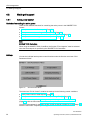
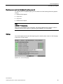
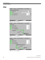
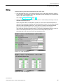
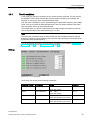
Settings
You set the individual active power control functions under the Service menu item "Grid
Parameters Menu".
Figure 4-2
Grid Parameters Menu
The menu item "P & Q Control" contains the settings for the following control conditions:
● Active power control to fixed setpoint (Page 39)
● Active power control in accordance with output voltage P = f(U) (Page 45)
You will find the settings for the Active power control during the switch-on operation
(Page 46) under the menu item "Active Power Ramps".
You will find the settings for the Active power control according to frequency P=f(f) (Page 40)
under the menu item "Frequency Derating".
PVS 600Series
38
Operating Instructions, 08/2014, A5E03467293-003
Grid management
4.2 Static grid support
4.2.1.1
Active power control to fixed setpoint
Function
The active power of the SINVERT PVS inverter can be limited to a fixed setpoint Pmax. The
setting is made as a percentage of the maximum rated power. This function is also used by
the SINVERT PVS ControlBox to implement the grid operator's specifications.
Note
SINVERT PVS ControlBox
When using the SINVERT PVS ControlBox, this value is overwritten cyclically.
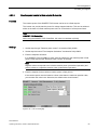
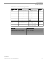
Settings
Figure 4-3
P & Q control [1/9]
Figure 4-4
P & Q control [3/9]
PVS 600Series
Operating Instructions, 08/2014, A5E03467293-003
39
Grid management
4.2 Static grid support
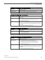
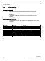
You activate or deactivate the active power control to a fixed setpoint using the following
three parameters:
Parameter number
Parameters
Range
Increment
33837
Activation 1 of Pmax controller
On
-
33838
Activation 2 of Pmax controller
On
Off
-
Off
For activating the active power control to a fixed setpoint, both parameters must be set to
"On".
For "Active power control to fixed setpoint", enter the setpoint in the field p32828.
4.2.1.2
Function
Parameter number
Parameters
Range
Increment
33828
P relative
0 … 100% of the rated power
1%
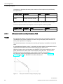
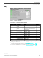
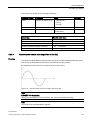
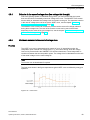
Active power control according to frequency P=f(f)
If the power grid contains more power than is currently used, the grid frequency increases.
The SINVERT PVS inverters detect an increase in the grid frequency and can reduce the
active power dependent on frequency.
The relationship between the output power and the grid frequency is predefined via the P(f)
curve.
If a parameterized frequency value f1 is exceeded, the active power Pf present at this time is
registered and thereafter used as the reference value for the P=f(f) curve.
While the frequency in the grid increases, the SINVERT PVS inverter supplies an output
power dependent on the level of the current frequency along the curve. The rise in the
PP=f(f) curve can be parameterized on the inverter by means of the gradient G.
If the frequency exceeds a parameterized frequency limit fH, see Chapter Frequency
monitoring (Page 74), the SINVERT PVS inverter switches off.
Figure 4-5
Active power control according to frequency P=f(f)
PVS 600Series
40
Operating Instructions, 08/2014, A5E03467293-003
Grid management
4.2 Static grid support
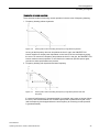
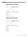
Resumption of normal operation:
There are three modes of resuming normal operation in the the case of frequency derating:
1. Frequency derating without hysteresis
Figure 4-6
Active power control according to frequency P=f(f) without hysteresis
As long as the frequency does not drop below the limit f1 again, the SINVERT PVS
inverter supplies an output power dependent on the level of the current frequency along
the curve. As soon as the frequency drops below the limit f1 in the grid, the SINVERT PVS
inverter resumes normal operation. It now feeds in the maximum possible power again,
provided no other specifications are present.
2. Frequency derating with hysteresis and start frequency
Figure 4-7
Active power control according to frequency P=f(f) with hysteresis and start
frequency
If a second limit frequency f2 (parameterizable) is exceeded, the inverter no longer follows
the curve, and instead remains at a constant output power Pf2(determined by the curve)
until the frequency has dropped below the end frequency for resuming normal operation
f3 (parameterizable).
PVS 600Series
Operating Instructions, 08/2014, A5E03467293-003
41
Grid management
4.2 Static grid support
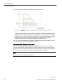
3. Frequency derating with hysteresis and without start frequency
Figure 4-8
Active power control according to frequency P=f(f) with hysteresis and start
frequency
Contrary to active power control according to frequency P=f(f) with hysteresis and start
frequency, the second limit frequency f2 is not required. The inverter generally no longer
follows the curve in the case of frequency derating, and instead remains at the minimum
calculated output power P (determined via the curve) until the final frequency for
resuming normal operation f3 (parameterizable) has been undershot.
Only one mode is parameterized for frequency-dependent active power reduction. You set
all parameters here, regardless of which mode is used.
Parameterization of a minimum holding power
A minimum holding power can be parameterized additionally for modes 1 and 3. Some
Grid Codes demand this. If this function is activated, the inverter will not reduce the output
power below the parameterized holding power. If the frequency f nevertheless continues to
rise, the inverter will be switched off when the frequency point fH is reached.
Note
The functions can be deactivated if required.
PVS 600Series
42
Operating Instructions, 08/2014, A5E03467293-003
Grid management
4.2 Static grid support
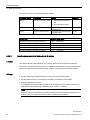
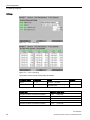
Settings
Figure 4-9
Frequency derating [1/1]
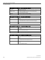
The function can be set via the following parameters:
Parameter number
Parameters
Range
Increment
33805
Activation of FB FControl
On
-
Frequency Derating
Mode
1. Hysteresis with start frequency
32320
Off
-
2. Hysteresis without start frequency
3. No hysteresis
32624
Limit frequency f1
50 Hz: 47 ... 53 Hz
60 Hz: 57 ... 62 Hz
0.01 Hz
32627
Limit frequency f2
50 Hz: 47 ... 53 Hz
60 Hz: 57 ... 62 Hz
0.01 Hz
32626
Limit frequency f3
50 Hz: 47 ... 53 Hz
60 Hz: 57 ... 62 Hz
0.01 Hz
32625
Gradient G
0.1 ... 1.51) 2)
0.01
-
Activate / deactivate
minimum power point
Hold power
-
Reduce power
Minimum power point
0…2500 kW
32325
0.1 kW
1)
Calculation of the gradient (without hysteresis): G = Pf / (fn-f1) ; where fn is the crossing point of the
derating curve and the x axis
2)
Calculation of the gradient (with hysteresis): G = (Pf - Pf2) / (f2 - f1)
You can find the setting options for fH in Chapter Frequency monitoring (Page 74).
PVS 600Series
Operating Instructions, 08/2014, A5E03467293-003
43
Grid management
4.2 Static grid support
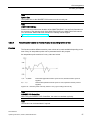
Example of setting a frequency reduction without hysteresis
Figure 4-10
Example of setting a frequency reduction without hysteresis
Pf = 100%
f1 = 50.2 Hz
f2 > fH ⇒ f2 = fH +0.1 Hz
f3 = 50.05 Hz
fH > 52.2 Hz ⇒ fH = 52.2 Hz +0.1 Hz
Example of setting a frequency reduction with hysteresis
Figure 4-11
Example of setting a frequency reduction with hysteresis
Pf = 100%
Pf2 = 60%
f1 = 50.2 Hz
f2 = 51.2 Hz
f3 = 50.05 Hz
fH = 51.5 Hz
PVS 600Series
44
Operating Instructions, 08/2014, A5E03467293-003
Grid management
4.2 Static grid support
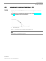
4.2.1.3
Active power control in accordance with output voltage P = f(U)
Function
The active power of the SINVERT PVS inverter can be reduced dependent on the output
voltage.
If the voltage exceeds a parameterized voltage limit UH, see Chapter Voltage monitoring
(Page 76), the SINVERT PVS inverter switches off.
PU
Actual active power
Figure 4-12
Active power control according to output voltage P = f(U)
Note
The function can be deactivated if required.
PVS 600Series
Operating Instructions, 08/2014, A5E03467293-003
45
Grid management
4.2 Static grid support
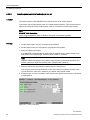
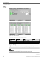
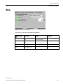
Settings
Figure 4-13
P & Q control [3/9]
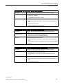
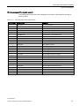
The function can be activated or deactivated via the following parameters:
Parameter number
Parameters
33842
Activation of characteristic Pmax(U)
Range
Increment
On
-
Off
You can find the setting options for UH in Chapter Voltage monitoring (Page 76).
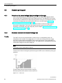
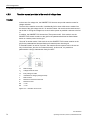
4.2.1.4
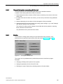
Active power control during the switch-on operation
Function
To avoid sudden variations in active power on the grid resulting from fast switch-on of the PV
plant, the SINVERT PVS inverter can increase its output via a parameterizable ramp. The
following options can be parameterized to stipulate when the output is to be increased via a
ramp:
● Never
● Only following grid fault
● At every start operation
The increase of the ramp over a gradient until the full rated active power Pn is reached can
continue to be parameterized.
The increase in the ramp is independent of the actually present active power. The active
power increases along the ramp up to the existing PV array power.
PVS 600Series
46
Operating Instructions, 08/2014, A5E03467293-003
Grid management
4.2 Static grid support
Figure 4-14
Active power control during the switch-on operation
Figure 4-15
Active power ramps [1/1]
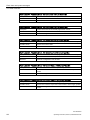
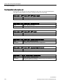
Settings
The function can be set via the following parameter:
Parameter number
Parameters
Range
32330
Type of ramp
•
No ramp (ramp deactivated)
•
Ramp after grid fault (standard)
•
INV start always with ramp
32331
Gradient of the increase
1 ... 100% of Pmax per minute
Increment
-
1%
PVS 600Series
Operating Instructions, 08/2014, A5E03467293-003
47
Grid management
4.2 Static grid support
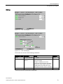
4.2.2
Reactive power control
Methods of controlling the reactive power
The increasingly strong trend towards integration of distributed generating plants into
distribution grids results in the rising challenge of voltage stability. It is possible to influence
the grid voltage by means of the reactive power. The SINVERT PVS inverters can be
operated with a reactive power corresponding to a power factor cosφ = 0.8 inductive (low
voltage / medium voltage) to cos φ = 0.8 capacitive.
Note
Negative values correspond to an inductive reactive power (overexcited operation) and
positive values to a capacitive reactive power (underexcited operation).
Reactive power control can be specified in accordance with five different functions:
● Reactive power control to absolute setpoint of Q or cos φ
● Reactive power control according to time of day Q(t) or cos φ (t)
● Reactive power control according to output voltage Q=f(U)
● Reactive power control according to active power cos φ (P)
● Reactive power control to relative fixed setpoint of Qmax
In general, a distinction must be made between two different bases when providing reactive
power:
● Reactive power control on the basis of the power factor cos φ
● Reactive power control on the basis of reactive power Q
Different functions are available depending on the basis selected.
Reactive power control on the basis of the power factor cos φ
For power factor cos φ (setpoint type), you can select one of the following functions (setpoint
source):
● Fixed setpoint
● cos φ (P) curve
● cos φ (t) curve
Note
SINVERT PVS ControlBox
When using the SINVERT PVS ControlBox, the function "Fixed setpoint" must be selected
since the fixed setpoint is specified by the SINVERT PVS ControlBox.
PVS 600Series
48
Operating Instructions, 08/2014, A5E03467293-003
Grid management
4.2 Static grid support
Reactive power control on the basis of reactive power Q
For reactive power Q (setpoint type), you can select one of the following functions (setpoint
source):
● Absolute fixed setpoint
● Q (U) curve
● Q (t) curve
● Relative fixed setpoint
Note
SINVERT PVS ControlBox
When using the SINVERT PVS ControlBox, the function "Absolute fixed setpoint" must be
selected since the fixed setpoint is specified by the SINVERT PVS ControlBox.
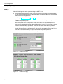
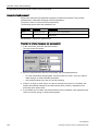
Settings
You set the setpoint source and the setpoint type for reactive power control on the first page
of the menu "P & Q Control".
Figure 4-16
P & Q control [1/9]
PVS 600Series
Operating Instructions, 08/2014, A5E03467293-003
49
Grid management
4.2 Static grid support
Figure 4-17
P & Q control [2/9]
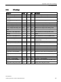
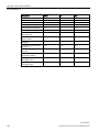
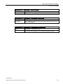
You activate / deactivate the respective active power control using the following three
parameters:
Parameter number
Parameters
Range
33824
Activation 1 of Q controller
•
On
•
Off
•
On
•
Off
•
Reactive power
•
cos(phi)
•
Fixed setpoint
•
f(U)/f(P) characteristic
•
Time-based setpoint
•
Relative setpoint for Q control
33825
33830
33833
Activation 2 of Q controller
Setpoint type
Setpoint
Increment
-
For activating the active power control to a fixed setpoint, p33824 and p33825 must be set to
"On".
PVS 600Series
50
Operating Instructions, 08/2014, A5E03467293-003
Grid management
4.2 Static grid support
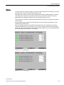
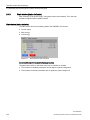
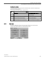
4.2.2.1
Reactive power control to fixed setpoint Q absolute
Function
The reactive power of the SINVERT PVS inverter can be set to a fixed setpoint.
The inverter can provide reactive power for voltage support/reduction. This can be achieved
either on the basis of a fixed reactive power value or on the basis of a fixed power factor.
Note
SINVERT PVS ControlBox
When using the SINVERT PVS ControlBox, this value is overwritten cyclically.
Settings
1. Set the setpoint type "Reactive power control" via selection field p33830.
2. Set the setpoint source "Fixed setpoint Q absolute" via selection field p33833.
3. Enter the setpoints as follows:
If no SINVERT PVS ControlBox is used, enter the setpoint for the reactive power in field
p32813 if the setpoint type "Reactive Power Control" is selected.
Note
Negative values correspond to an inductive reactive power (overexcited operation) and
positive values to a capacitive reactive power (underexcited operation).
4. Enter the setpoint for the maximum reactive power in field p33104.
If the reactive power must be limited to a lower value than the maximum possible value,
you can enter this value here. Otherwise, the default value should remain.
Figure 4-18
P & Q control [2/9]
PVS 600Series
Operating Instructions, 08/2014, A5E03467293-003
51
Grid management
4.2 Static grid support
The function can be set via the following parameters:
4.2.2.2
Parameter number
Parameters
Range
33833
Selection of setpoint source
•
Fixed setpoint Q absolute
•
Q(t)
•
Fixed setpoint Q relative
Increment
-
32813
Fixed setpoint of reactive
power
Dependent on the inverter type, 1 kVAR
see table below
33104
Maximum reactive power
Dependent on the inverter type, 1 kVAR
see table below
Inverter type
Reactive power range
PVS500 / PVS1000 / PVS1500 / PVS2000
- 300 … + 300 kVAR
PVS525 / PVS1050 / PVS1575 / PVS2100
- 315 … + 315 kVAR
PVS585 / PVS1170 / PVS1755 / PVS2340
- 351 … + 351 kVAR
PVS600 / PVS1200 / PVS1800 / PVS2400
- 360 … + 360 kVAR
PVS630 / PVS1260 / PVS1890 / PVS2520
- 378 … + 378 kVAR
Reactive power control to fixed setpoint Q relative
Function
The reactive power of the SINVERT PVS inverter can be set to a relative fixed setpoint.
The inverter can provide reactive power for voltage support/reduction. This can be achieved
either on the basis of a fixed reactive power value or on the basis of a fixed power factor.
Settings
1. Set the setpoint type "Reactive power control" via selection field p33830.
2. Set the setpoint source "Fixed setpoint Q relative" via selection field p33833.
3. Enter the setpoints as follows:
If no SINVERT PVS ControlBox is used, enter the setpoint for the reactive power in the
field p32814 if the setpoint type "Reactive power control" is selected.
Note
Negative values correspond to an inductive reactive power (overexcited operation) and
positive values to a capacitive reactive power (underexcited operation).
PVS 600Series
52
Operating Instructions, 08/2014, A5E03467293-003
Grid management
4.2 Static grid support
4. Enter the setpoint for the maximum reactive power in field p33104.
If the reactive power must be limited to a lower value than the maximum possible value,
you can enter this value here. Otherwise, the default value should remain.
Figure 4-19
P & Q control [2/9]
The function can be set via the following parameters:
Parameter number
Parameters
Range
33833
Selection of setpoint source
•
Fixed setpoint Q absolute
•
Q(t)
•
Fixed setpoint Q relative
Increment
-
32814
Fixed setpoint of reactive
power
Dependent on the inverter
type, see table below
1 kVAR
33104
Maximum reactive power
Dependent on the inverter
type, see table below
1 kVAR
Inverter type
Reactive power range
PVS500 / PVS1000 / PVS1500 / PVS2000
- 300 … + 300 kVAR
PVS525 / PVS1050 / PVS1575 / PVS2100
- 315 … + 315 kVAR
PVS585 / PVS1170 / PVS1755 / PVS2340
- 351 … + 351 kVAR
PVS600 / PVS1200 / PVS1800 / PVS2400
- 360 … + 360 kVAR
PVS630 / PVS1260 / PVS1890 / PVS2520
- 378 … + 378 kVAR
PVS 600Series
Operating Instructions, 08/2014, A5E03467293-003
53
Grid management
4.2 Static grid support
4.2.2.3
Reactive power control to fixed setpoint cos phi
Function
The reactive power of the SINVERT PVS inverter can be set to a fixed setpoint.
The inverter can provide reactive power for voltage support/reduction. This can be achieved
either on the basis of a fixed reactive power value or on the basis of a fixed power factor.
Note
SINVERT PVS ControlBox
When using the SINVERT PVS ControlBox, this value is overwritten cyclically.
Settings
1. Set the setpoint type "cos phi" via selection field p33830.
2. Set the setpoint source "Fixed setpoint" via selection field p33833.
3. Enter the setpoints as follows:
If no SINVERT PVS ControlBox is used, enter the setpoint for the reactive power in the
field p32812 if the setpoint type "Reactive power control" is selected.
Note
Negative values correspond to an inductive reactive power (overexcited operation) and
positive values to a capacitive reactive power (underexcited operation).
4. Enter the setpoint for the maximum reactive power in field p33104.
If the reactive power must be limited to a lower value than the maximum possible value,
you can enter this value here. Otherwise, the default value should remain.
5. If setpoint type "cos phi" is selected, enter the minimum (p32615) and maximum (p32616)
cos phi setpoint.
Figure 4-20
P & Q control [2/9]
PVS 600Series
54
Operating Instructions, 08/2014, A5E03467293-003
Grid management
4.2 Static grid support
The function can be set via the following parameters:
4.2.2.4
Function
Parameter number
Parameters
33833
Selection of setpoint source
Range
•
Fixed setpoint
•
cos φ(t)
•
cos φ(P)
Increment
-
32812
Power factor
-0.8 … 1 … 0.8
33104
Maximum reactive power
Dependent on the inverter type, 1 kVAR
see table below
Inverter type
Reactive power range
PVS500 / PVS1000 / PVS1500 / PVS2000
- 300 … + 300 kVAR
PVS525 / PVS1050 / PVS1575 / PVS2100
- 315 … + 315 kVAR
PVS585 / PVS1170 / PVS1755 / PVS2340
- 351 … + 351 kVAR
PVS600 / PVS1200 / PVS1800 / PVS2400
- 360 … + 360 kVAR
PVS630 / PVS1260 / PVS1890 / PVS2520
- 378 … + 378 kVAR
0.01
Reactive power control according to time of day Q(t)
This function enables different reactive power values to be made available depending on the
time of day. 24 interpolation points can be parameterized for this purpose.
An interpolation point consists of a reactive power Q and a time t.
Figure 4-21
Reactive power control according to time of day Q(t)
Note
SINVERT PVS ControlBox
When using the SINVERT PVS ControlBox, this value is overwritten cyclically.
Note
This function can be deactivated if required.
PVS 600Series
Operating Instructions, 08/2014, A5E03467293-003
55
Grid management
4.2 Static grid support
Settings
Figure 4-22
P & Q control [2/9]
Figure 4-23
P & Q control [4/9]
The function can be set via the following parameters:
Parameter number
Parameters
Range
Increment
33101
t0 ... t23
00:00:00 ... 23:59:59
1s
33100
Reactive power Q
Dependent on the inverter type,
see table below
0.01 kVAR
Inverter type
Reactive power range
PVS500 / PVS1000 / PVS1500 / PVS2000
- 300 … + 300 kVAR
PVS525 / PVS1050 / PVS1575 / PVS2100
- 315 … + 315 kVAR
PVS585 / PVS1170 / PVS1755 / PVS2340
- 351 … + 351 kVAR
PVS600 / PVS1200 / PVS1800 / PVS2400
- 360 … + 360 kVAR
PVS630 / PVS1260 / PVS1890 / PVS2520
- 378 … + 378 kVAR
PVS 600Series
56
Operating Instructions, 08/2014, A5E03467293-003
Grid management
4.2 Static grid support
Note
System time
The system time on the SINVERT PVS inverter must be correctly set.
Note
SIMOTION D425 time
Please note the possible time deviation of the SIMOTION D425. You can find information on
the accuracy of the real-time clock of the SIMOTION D425 in the SIMOTION D4x5 manual.
You can find the SIMOTION D4x5 manual in the Industry Online Support
(http://support.automation.siemens.com).
4.2.2.5
Function
Reactive power control by means of cos φ (t) according to time of day
This function enables different reactive power values to be made available depending on the
time of day. 24 interpolation points can be parameterized for this purpose.
An interpolation point consists of a cos φ value and a time.
-0,8 … -0,99999
Overexcited (capacitive reactive power is used, inductive reactive power is
supplied)
0,8 … 1,0
Underexcited (inductive reactive power is used, capacitive reactive power is
supplied)
Figure 4-24
Reactive power control by means of cos φ (t) according to time of day
Note
SINVERT PVS ControlBox
When using the SINVERT PVS ControlBox, this value is overwritten cyclically.
Note
This function can be deactivated if required.
PVS 600Series
Operating Instructions, 08/2014, A5E03467293-003
57
Grid management
4.2 Static grid support
Settings
Figure 4-25
P & Q control [2/9]
Figure 4-26
P & Q control [5/9]
The function can be set via the following parameters:
Parameter number
Parameters
Range
Increment
33103
t0 ... t23
00:00:00 ... 23:59:59
1s
33102
cos φ1 ... cos φ23
0,8ind ... 1 ... 0.8cap
0,001
Note
Setpoints (p33102)
Negative values correspond to an inductive reactive power (overexcited operation) and
positive values to a capacitive reactive power (underexcited operation).
Note
System time
The system time on the SINVERT PVS inverter must be correctly set.
PVS 600Series
58
Operating Instructions, 08/2014, A5E03467293-003
Grid management
4.2 Static grid support
Note
SIMOTION D425 time
Please note the possible time deviation of the SIMOTION D425. You can find information on
the accuracy of the real-time clock of the SIMOTION D425 in the SIMOTION D4x5 manual.
You can find the SIMOTION D4x5 manual in the Industry Online Support
(http://support.automation.siemens.com).
4.2.2.6
Reactive power control in accordance with output voltage Q=f(U)
Function
The SINVERT PVS inverters can feed voltage-level-dependent reactive power into the grid
(reactive power/voltage curve Q(U)).
The curve can be parameterized via two voltage limit values U1 and U2. The voltage limits
are specified as percentages of the rated voltage. The maximum reactive power Q1 (= - Q2)
can also be parameterized.
Figure 4-27
Reactive power control according to output voltage Q=f(U)
Note
SINVERT PVS ControlBox
When using the SINVERT PVS ControlBox, this value is overwritten cyclically.
Note
The function can be deactivated if required.
PVS 600Series
Operating Instructions, 08/2014, A5E03467293-003
59
Grid management
4.2 Static grid support
Settings
Figure 4-28
P & Q control [2/9]
Figure 4-29
P & Q control [6/9]
Figure 4-30
P & Q control [7/9]
PVS 600Series
60
Operating Instructions, 08/2014, A5E03467293-003
Grid management
4.2 Static grid support
The function can be set via the following parameters:
Parameter number
Parameters
Range
Increment
32688
Lower reactive power value Q2
0 … 100% of the maximum
reactive power
0.01 %
32689
Lower reactive power value Q1
0 … 100% of the maximum
reactive power
0.01 %
32690
Upper reactive power value Q3
0 … 100% of the maximum
reactive power
0.01 %
32691
Upper reactive power value Q4
0 … 100% of the maximum
reactive power
0.01 %
32710
Lower voltage limit value U1
0 … 100 % of the AC rated
voltage
0.01 %
32711
Lower voltage limit value U1
0 … 100 % of the AC rated
voltage
0.01 %
32712
Upper voltage limit value U1
100 ... 200 %
0.01 %
of the AC rated voltage
32713
Upper voltage limit value U2
100 ... 200 %
0.01 %
of the AC rated voltage
Inverter type
Reactive power range
PVS500 / PVS1000 / PVS1500 / PVS2000
- 300 … + 300 kVAR
PVS525 / PVS1050 / PVS1575 / PVS2100
- 315 … + 315 kVAR
PVS585 / PVS1170 / PVS1755 / PVS2340
- 351 … + 351 kVAR
PVS600 / PVS1200 / PVS1800 / PVS2400
- 360 … + 360 kVAR
PVS630 / PVS1260 / PVS1890 / PVS2520
- 378 … + 378 kVAR
PVS 600Series
Operating Instructions, 08/2014, A5E03467293-003
61
Grid management
4.2 Static grid support
4.2.2.7
Reactive power control according to active power cos φ (P)
Function
The SINVERT PVS inverters can feed reactive power into the grid dependent on the level of
the actual active power P (power factor/power curve cos φ (P)). The curve can be
parameterized via two limit values. The limit values are specified as percentages of the rated
power. The maximum cos φ1 (= - cos φ2) can also be parameterized.
Figure 4-31
Reactive power control according to cos φ (P)
Note
SINVERT PVS ControlBox
When using the SINVERT PVS ControlBox, this value is overwritten cyclically.
Note
The function can be deactivated if required.
PVS 600Series
62
Operating Instructions, 08/2014, A5E03467293-003
Grid management
4.2 Static grid support
Settings
Figure 4-32
P & Q control [2/9]
The function can be set via the following parameters:
Parameter number
Parameters
Range
Increment
32661
Lower power tolerance
limit
10.0 ... 100.0 %
0.01 %
of the rated power
Upper power tolerance
limit
of the rated power
32660
100.0 ... 140.0 %
0.01 %
32615
Min. setpoint cos φ1
(= - cos φ2)
-0.9 ... -0.8
0.01
32616
Max. setpoint cos φ1
(= - cos φ2)
0,8 ... 1,0
0,01
PVS 600Series
Operating Instructions, 08/2014, A5E03467293-003
63
Grid management
4.3 Dynamic grid support
4.3
Dynamic grid support
4.3.1
Behavior in the case of voltage dips (low voltage ride through)
Due to the growing spread of renewable energy forms, you must ensure that the inverter
does not shut down immediately when brief voltage dips occur. The SINVERT PVS inverter
has the ability to withstand brief voltage dips and remain on the grid. The shutdown behavior
in the case of voltage dips can be set via the LVRT curve, see the chapter "Shutdown
behavior in the event of voltage dips (Page 64)".
The SINVERT PVS inverter can continue to provide reactive current for voltage support
during these voltage dips. The level of the reactive current can be set via the k factor
depending on the depth of the grid voltage dip, see the chapter "Reactive current provision in
the event of voltage dips (Page 67)".
4.3.2
Function
Shutdown behavior in the event of voltage dips
The LVRT curve can be parameterized by means of up to 10 interpolation points. An
interpolation point consists of a voltage level U / Un and a time t during which the voltage
level can be present before the SINVERT PVS inverter shuts down. Linear interpolation is
carried out between the two interpolation points. The voltage level is calculated from the ratio
of the actual voltage U to the rated voltage Un.
Note
The function can be deactivated if required.
The limit curve shown in the figure represents a typical LVRT curve as defined by many grid
operators.
①
②
Range within which the inverter remains on the grid.
Range (shaded) within which the inverter switches off.
Figure 4-33
LVRT curve
PVS 600Series
64
Operating Instructions, 08/2014, A5E03467293-003
Grid management
4.3 Dynamic grid support
Settings
Note the following points when parameterizing the LVRT curve:
● The parameterized LVRT curve must correspond to the undervoltage protection settings.
For this reason, parameterize two of the interpolation points identically to the entered limit
values of the undervoltage monitor.
See Chapter Voltage monitoring (Page 76).
● When parameterizing, all fields must be filled, but it is not absolutely necessary to use all
available interpolation points.
When using fewer than 10 interpolation points, the order of the entered interpolation is
decisive since interpolation between the individual points is linear. For this reason, always
enter the used interpolation points first. Then enter the values of the last interpolation
point in the subsequent fields for the interpolation points that are not required.
You will find an example in the figure below. The first four interpolation points (0 to 4) are
used. All the subsequent fields (5 to 9) for the unused interpolation points are
parameterized in the same way as the last interpolation point.
Figure 4-34
LVRT & HVRT [1/5]
Figure 4-35
LVRT & HVRT [2/5]
PVS 600Series
Operating Instructions, 08/2014, A5E03467293-003
65
Grid management
4.3 Dynamic grid support
The function can be set via the following parameters:
Parameter number
Parameters
Range
Increment
32075
LVRT activation
On
-
33140
LVRT mode
Off
32090
LVRT reactive power response
•
Standard mode
•
Zero power mode
•
Q mode
•
k factor mode
•
Advanced mode
-
-
33111
Time t
0 ... 60000 ms
1 ms
33110
Voltage level U / UC
0 ... 100 %
0.01 %
Example: Set time 200 ms and set voltage level of 5 % ⇒ If the voltage is continuously less
than 5% Urated for longer than 200 ms, the inverter switches off.
PVS 600Series
66
Operating Instructions, 08/2014, A5E03467293-003
Grid management
4.3 Dynamic grid support
4.3.3
Reactive current provision in the event of voltage dips
Function
In the event of a voltage dip, the SINVERT PVS inverter can provide reactive current for
voltage stability.
The level of the reactive current ΔIB / In additionally fed in when a fault occurs results from
the depth of the grid voltage dip ΔU / Un and the k factor. No more than the rated current In
can be fed in. During the voltage dip, as much active power as possible continues to be fed
in.
In addition, the SINVERT PVS inverter has "Zero power mode". If this mode is set, the
SINVERT PVS inverter remains on the grid for the parameterized time but feeds neither
active nor reactive power into the grid.
"Q mode" is another mode. If this mode is set, the SINVERT PVS inverter remains on the
grid for the parameterized time and feeds pure reactive power into the grid.
In "Standard mode" as well as "Q mode", the reactive current response can be be set not
only via the k factor, but also via "Advanced mode". In this mode, it is possible to
parameterize a Q=f(U) characteristic freely for LVRT.
Un
Rated voltage
U0
Voltage before the fault
US
Entry voltage of LVRT
U
Instantaneous voltage (during the fault)
In
Rated current
IB0
Reactive current before the fault
IB
Reactive current
ΔU
= U-U0
ΔIB
= IB-IB0
Figure 4-36
Reactive current curve
PVS 600Series
Operating Instructions, 08/2014, A5E03467293-003
67
Grid management
4.3 Dynamic grid support
Settings
Figure 4-37
LVRT & HVRT [3/5]
Figure 4-38
LVRT & HVRT [3/5]
The function can be set via the following parameters:
Parameter number Parameters
Range
Increment
33135
Current limit for FRT
0 ... 100 %
0.01 %
33129
Entry voltage of
LVRT US
0 ... 100 %
0.01 %
of the rated voltage
Example: A voltage dip of around
10% means 90% remaining grid voltage
related to the rated voltage. Continuous
operation takes place before this value.
LVRT takes over if this value is exceeded.
33128
k factor*
0.0 ... 6.0
0.1
* Can only be set if zero power mode is deactivated
PVS 600Series
68
Operating Instructions, 08/2014, A5E03467293-003
Grid management
4.3 Dynamic grid support
4.3.4
Behavior in the case of voltage rises (low voltage ride through)
Due to the growing spread of renewable energy forms, you must ensure that the inverter
does not shut down immediately when brief voltage rises occur. The SINVERT PVS inverter
has the ability to withstand brief voltage rises and remain on the grid. The shutdown behavior
in the case of voltage rises can be set via the HVRT curve, see the chapter "Shutdown
behavior in the event of voltage rises (Page 69)".
The SINVERT PVS inverter can continue to provide reactive current for voltage reduction
during these voltage rises. The level of the reactive current can be set via the k factor
depending on the extent of the grid voltage rise, see the chapter "Reactive current provision
in the event of voltage rises (Page 72)".
4.3.5
Shutdown behavior in the event of voltage rises
Function
The HVRT curve can be parameterized by means of up to 10 interpolation points. An
interpolation point consists of a voltage level U / Un and a time t during which the voltage
level can be present before the SINVERT PVS inverter shuts down. Linear interpolation is
carried out between the two interpolation points. The voltage level is calculated from the ratio
of the actual voltage U to the rated voltage Un.
Note
The function can be deactivated if required.
The limit curve shown in the figure represents a typical HVRT curve as defined by many grid
operators.
Figure 4-39
HVRT curve
PVS 600Series
Operating Instructions, 08/2014, A5E03467293-003
69
Grid management
4.3 Dynamic grid support
Settings
Note the following points when parameterizing the HVRT curve:
● The parameterized HVRT curve must correspond to the undervoltage protection settings.
For this reason, parameterize two of the interpolation points identically to the entered limit
values of the overvoltage monitor.
See Chapter Voltage monitoring (Page 76).
● When parameterizing, all fields must be filled, but it is not absolutely necessary to use all
available interpolation points.
When using fewer than 10 interpolation points, the order of the entered interpolation is
decisive since interpolation between the individual points is linear. For this reason, always
enter the used interpolation points first. Then enter the values of the last interpolation
point in the subsequent fields for the interpolation points that are not required.
You will find an example in the figure below. The first four interpolation points (0 to 5) are
used. All the subsequent fields (6 to 9) for the unused interpolation points are
parameterized in the same way as the last interpolation point.
Figure 4-40
LVRT & HVRT [1/5]
Figure 4-41
LVRT & HVRT [4/5]
PVS 600Series
70
Operating Instructions, 08/2014, A5E03467293-003
Grid management
4.3 Dynamic grid support
The function can be set via the following parameters:
Parameter number
Parameters
Range
Increment
32077
HVRT activation
On
-
33141
HVRT mode
Off
32091
HVRT reactive power response
•
Standard mode
•
Zero power mode
•
Q mode
•
k factor mode
•
Advanced mode
-
-
33116
Time t
0 ... 60000 ms
1 ms
33115
Voltage level U / UC
100 ... 200 %
0.01 %
Example: Set time 200 ms and set voltage level of 117 % ⇒ If the voltage is continuously
less than 117 % Urated for longer than 200 ms, the inverter switches off.
PVS 600Series
Operating Instructions, 08/2014, A5E03467293-003
71
Grid management
4.3 Dynamic grid support
4.3.6
Reactive current provision in the event of voltage rises
Function
In the event of a voltage rise, the SINVERT PVS inverter can provide reactive current for
voltage reduction.
The level of the reactive current ΔIB / In additionally fed in when a fault occurs results from
the extent of the grid voltage rise ΔU / Un and the k factor. No more than the rated current In
can be fed in. During the voltage rise, as much active power as possible continues to be fed
in.
In addition, the SINVERT PVS inverter has "Zero power mode". If this mode is set, the
SINVERT PVS inverter remains on the grid for the parameterized time but feeds neither
active nor reactive power into the grid.
"Q mode" is another mode. If this mode is set, the SINVERT PVS inverter remains on the
grid for the parameterized time and feeds pure reactive power into the grid.
In "Standard mode" as well as "Q mode", the reactive current response can be be set not
only via the k factor, but also via "Advanced mode". In this mode, it is possible to
parameterize a Q=f(U) characteristic freely for HVRT.
Un
Rated voltage
U0
Voltage before the fault
US
Entry voltage of LVRT
U
Instantaneous voltage (during the fault)
In
Rated current
IB0
Reactive current before the fault
IB
Reactive current
ΔU
= U-U0
ΔIB
= IB-IB0
Figure 4-42
Reactive current curve
PVS 600Series
72
Operating Instructions, 08/2014, A5E03467293-003
Grid management
4.3 Dynamic grid support
Settings
Figure 4-43
LVRT & HVRT [5/5]
Figure 4-44
LVRT & HVRT [5/5]
The function can be set via the following parameters:
Parameter number Parameters
Range
Increment
33135
Current limit for FRT
0 ... 100 %
0.01 %
33131
Entry voltage of
HVRT US
100 ... 200 %
0.01 %
of the rated voltage
Example: A voltage dip of around
10% means 110% remaining grid voltage
related to the rated voltage. Continuous
operation takes place before this value.
HVRT takes over if this value is exceeded.
33130
k factor*
0.0 ... 6.0
0.1
* Can only be set if zero power mode is deactivated
PVS 600Series
Operating Instructions, 08/2014, A5E03467293-003
73
Grid management
4.4 Decoupling protection
4.4
Decoupling protection
4.4.1
Grid monitoring
Function
The SINVERT PVS inverter monitors the public energy grid for violations of adjustable grid
frequency and grid voltage limits. If the limits are violated for an adjustable time, the inverter
disconnects from the grid.
4.4.2
Frequency monitoring
Function
The SINVERT PVS inverter monitors the grid frequency during operation. If a certain
frequency range is exceeded or undershot, a grid fault can be assumed, and shutdown of
the SINVERT PVS inverter is necessary. Up to six parameterizable limits for both
overfrequency and underfrequency are available for shutdown outside the permissible
frequency range.
A frequency and a tripping delay time can be parameterized for each limit.
If the grid frequency is outside the parameterizable range, the SINVERT PVS inverter shuts
down, and a fault message is output.
As soon as the grid frequency returns to the permissible range, the fault message is
automatically acknowledged.
If the grid is within the specified limits for restarting, see the chapter "Feed-in conditions
(Page 79)", the inverter powers up again automatically.
PVS 600Series
74
Operating Instructions, 08/2014, A5E03467293-003
Grid management
4.4 Decoupling protection
Settings
On the "Frequency monitoring" pages, you set the upper and lower limit values (in %) for the
grid frequency, as well as the associated delay (in ms).
The delay is the minimum time for which a fault must be active to effect shutdown. If the set
limit values are undershot or exceeded for the set time, the inverter switches off with an
appropriate fault message. Shutdown of the inverter takes approx. 80 ms.
The required limit values for overfrequency/underfrequency refer to the rated grid frequency
of the inverter.
When parameterizing, all fields must be filled, but it is not absolutely necessary to use all
available interpolation points.
When using fewer than the two available interpolation points, the sequential order of the
entered interpolation points is decisive. For this reason, always enter the used interpolation
points first. Then enter the values of the last used interpolation point in the subsequent fields
for the interpolation points that are not required.
Figure 4-45
Low voltage [3/5]
Figure 4-46
Low voltage [4/5]
PVS 600Series
Operating Instructions, 08/2014, A5E03467293-003
75
Grid management
4.4 Decoupling protection
The function can be set via the following parameters:
Parameter number
Parameters
32670
Overfrequency moni- 100 ... 150 %
toring fH 1
of the rated frequency (50 / 60 Hz)
0.1 %
32672
Overfrequency moni- 100 ... 150 %
toring fH 2
of the rated frequency (50 / 60 Hz)
0.1 %
32674
Underfrequency
monitoring fH 1
10 ... 100 %
0.1 %
Underfrequency
monitoring fH 2
10 ... 100 %
32676
4.4.3
Range
Increment
of the rated frequency (50 / 60 Hz)
0.1 %
of the rated frequency (50 / 60 Hz)
32671
Tripping delay time tf 0 ... 600000 ms
for overfrequency
monitoring fH 1
1 ms
32673
Tripping delay time tf 0 ... 600000 ms
for overfrequency
monitoring fH 2
1 ms
32675
Tripping delay time tf 0 ... 600000 ms
for underfrequency
monitoring fH 1
1 ms
32677
Tripping delay time tf 0 ... 600000 ms
for underfrequency
monitoring fH 2
1 ms
Voltage monitoring
Function
The SINVERT PVS inverter monitors the grid voltage during operation. If a certain voltage
range is exceeded or undershot, a grid fault can be assumed, and shutdown of the SINVERT
PVS inverter is necessary. Up to two parameterizable limits are available for shutdown
outside the permissible voltage range, both for overvoltage and undervoltage.
You can parameterize a voltage and a tripping delay time for each limit.
If the grid voltage is outside the parameterizable range, the SINVERT PVS inverter shuts
down, and a fault message is output.
As soon as the grid voltage returns to the permissible range, the fault message is
automatically acknowledged.
If the grid is within the specified limits for restarting, see the chapter "Feed-in conditions
(Page 79)", the inverter powers up again automatically.
PVS 600Series
76
Operating Instructions, 08/2014, A5E03467293-003
Grid management
4.4 Decoupling protection
Settings
On the "Overvoltage monitoring" and "Undervoltage monitoring" pages, you set the upper
and lower limit values (in %) for the voltage, as well as the associated delay (in ms).
The delay is the minimum time for which a fault must be active to effect shutdown. If the set
limit values are undershot or exceeded for the set time, the inverter switches off with an
appropriate fault message. Shutdown of the inverter takes approx. 80 ms.
The required limits refer to the AC rated voltage of the inverter.
Figure 4-47
Low voltage [1/5]
Figure 4-48
Low voltage [2/5]
Note
The parameterized LVRT curve must correspond to the undervoltage protection settings. For
this reason, parameterize two interpolation points of the LVRT curve identically to the
entered limit values of the undervoltage monitor.
See Chapter Shutdown behavior in the event of voltage dips (Page 64).
PVS 600Series
Operating Instructions, 08/2014, A5E03467293-003
77
Grid management
4.4 Decoupling protection
The function can be set via the following parameters:
Parameter number
Parameters
Range
Increment
32662
Overvoltage monitoriong 1
100 ... 150 %
0.1 %
32664
Overvoltage monitoriong 2
of the rated voltage
100 ... 150 %
0.1 %
of the rated voltage
32666
Undervoltage monitoring 1
0 ... 100 %
0.1 %
of the rated voltage
32668
Undervoltage monitoring 2
0 ... 100 %
0.1 %
of the rated voltage
32663
Tripping delay time tU for overvoltage
monitoring 1
0 ... 600000 ms
1 ms
32335
Tripping delay time tU for overvoltage
monitoring 2
0 ... 600000 ms
1 ms
32667
Tripping delay time tU for undervoltage
monitoring 1
0 ... 600000 ms
1 ms
32669
Tripping delay time tU for undervoltage
monitoring 2
0 ... 600000 ms
1 ms
PVS 600Series
78
Operating Instructions, 08/2014, A5E03467293-003
Grid management
4.4 Decoupling protection
4.4.4
Feed-in conditions
In the event of a grid fault, connection of the inverter must be prevented. For this purpose,
the SINVERT PVS inverter monitors the grid with regard to frequency and voltage, and
switches on if the grid is within a parameterizable range.
One limit each is available to you for parameterizing the permissible frequency and voltage
range. If the grid is within the parameterized limits, and if all restart conditions have been
met, the inverter powers up again automatically.
The voltage limits are input as a percentage of the rated voltage; the frequency limits are
input as a percentage of the rated frequency (50 / 60 Hz).
Note
The connection conditions range must be smaller than the shutdown conditions range to
avoid the constant on and off switching of the inverter when operating in limit ranges of the
permissible rated voltage/frequency.
You will find further information on the shutdown conditions in the chapters "Frequency
monitoring (Page 74)" and "Voltage monitoring (Page 76)".
Settings
Figure 4-49
Low voltage [5/5]
The function can be set via the following parameters:
Parameter number
Parameters
32682
Undervoltage limit
Range
Increment
80 ... 100 %
0.01 %
of the rated voltage
32683
Overvoltage limit
100 ... 115 %
0.01 %
of the rated voltage
32685
Underfrequency limit
32686
Overfrequency limit
90 ... 100 %
0.01 %
of the rated frequency (50 / 60 Hz)
100 ... 103 %
0,01 %
of the rated frequency (50 / 60 Hz)
PVS 600Series
Operating Instructions, 08/2014, A5E03467293-003
79
Grid management
4.4 Decoupling protection
PVS 600Series
80
Operating Instructions, 08/2014, A5E03467293-003
Application planning
5
The following chapter contains detailed information about packaging, dispatch, delivery,
storage, transport, installation location and configuring. Always read and follow the
instructions given in this documentation. Observe the relevant safety notices at all times.
Make sure that the conditions specified for storage, transport and installation location are
fulfilled.
5.1
Packaging, dispatch and delivery
Further information about the transport packaging used, dispatch of the inverter by Siemens
and the measures to be taken following delivery of the unit is given below.
5.1.1
Transport packaging
Envelope
The inverter cabinet sections are packaged in a loose-fitting plastic envelope which must not
be tightly stuck or tied to the cabinets at the bottom.
Transport pallet
The inverter cabinet sections are mechanically coupled with the pallet:
● on the one hand with strapping around the pallet and inverter
● and on the other by bolting the cabinet on the pallet using a bracket
PVS 600Series
Operating Instructions, 08/2014, A5E03467293-003
81
Application planning
5.1 Packaging, dispatch and delivery
Design
The basic design of the transport pallet is shown in the figure below.
This is a customized version of the pallet.
● This is made necessary on the one hand by the dimensions of the cabinet sections
● and on the other hand, this design offers sufficient mechanical stability for safe lifting by a
crane.
Figure 5-1
Dimensions of the transport pallet
PVS 600Series
82
Operating Instructions, 08/2014, A5E03467293-003
Application planning
5.1 Packaging, dispatch and delivery
5.1.2
Center of gravity marking and transport position
Center of gravity marking
The weight mass of the cabinet sections is distributed eccentrically and asymmetrically on
both the front and side faces. The weight distribution is indicated directly on each cabinet
section of the inverter by the center of gravity marking in accordance with ISO 780/Symbol 7.
Figure 5-2
Center of gravity marking on inverter
Transport position
The inverter must never be tipped.
Always observe the specified vertical transport position.
5.1.3
Dispatch and delivery
The inverter is delivered in two transport units. Each cabinet section is transported on a
special pallet. The transport units are checked by Siemens prior to dispatch to ensure that
they are correctly packaged and free of damage.
5.1.4
Checking the consignment
Please check that the consignment is complete against the accompanying dispatch
documentation. If any items are missing from the consignment, please notify the relevant
contact person immediately.
PVS 600Series
Operating Instructions, 08/2014, A5E03467293-003
83
Application planning
5.2 Transport
5.1.5
Scope of supply
The scope of supply of the SINVERT PVS inverter includes the following:
● Inverter AC cabinet mounted on transport pallet
● Inverter DC cabinet mounted on transport pallet
● Accessories pack (on Euro pallet):
– 1 x cable 4 m fitted with lugs at both ends, on pallet
– 1 x mounting kit for screwing the cabinet sections in black crate
– Hexagonal screw M12x50, strain washer, hexagonal nut
● Operating instructions (compact) as hard copy
5.2
Transport
The methods described below are the only permitted methods for transporting the SINVERT
PVS. No other method of transport is permitted. Siemens shall not accept liability for any
personal injuries or property damage resulting from the transportation of the product by an
improper method.
In addition to the safety notices applicable to specific transport methods, the general safety
instructions must also be noted and followed.
5.2.1
General safety instructions for transporting
The general safety instructions must always be followed regardless of the method of
transport. These mainly refer to the mechanical connection between the pallet and the
inverter cabinet section, to the mechanical connection between individual inverters, and to
the risk of tipping.
PVS 600Series
84
Operating Instructions, 08/2014, A5E03467293-003
Application planning
5.2 Transport
Mechanical connection between pallet and inverter cabinet section
● Never transport the pallet with the inverter cabinet section without a secure mechanical
connection between the pallet and inverter. See the figure below.
● The mechanical connection comprises strapping and bolting of cabinet base to the pallet.
● Before the package is moved, the bolting and strapping must be checked to ensure they
are secure.
● Please also note the safety notice regarding the risk of tipping if the pallet and cabinet are
not mechanically connected.
Figure 5-3
Transport packaging – Mechanical connection with the transport pallet
WARNING
Danger to life through tipping due to lack of mechanical connection with the pallet
The cabinet may be transported only if it is securely mechanically coupled with the pallet
(strapping and bolting). If the load is not securely coupled, it can tip or fall off the pallet.
In this case, the high weight mass of the cabinets can cause serious injuries, death and
substantial property damage.
PVS 600Series
Operating Instructions, 08/2014, A5E03467293-003
85
Application planning
5.2 Transport
Danger of tipping of the transportation unit
WARNING
Danger to life from tipping!
A cabinet, whether with or without pallet, must never be tipped in any direction. The cabinet
is very heavy. Tipping it too far and causing it to topple over can therefore result in serious
injury, death and substantial property damage.
Figure 5-4
Impermissible tipping of cabinets and pallets
PVS 600Series
86
Operating Instructions, 08/2014, A5E03467293-003
Application planning
5.2 Transport
Mechanical connection between the inverters
The SINVERT inverter is transported in two consignment units or cabinet sections. No
provision is made for transporting connected cabinet sections.
Figure 5-5
Impermissible transport of two cabinet sections
The inverter cabinet sections must never be transported once they have been assembled
into a single unit.
WARNING
Danger to life from transport of assembled cabinet sections!
Owing to their design, cabinet sections must never be transported once they have been
mechanically assembled into a single unit. Cabinet sections must always be transported as
a single unit by one of the permitted methods of transport. The heavy weight of the cabinets
means that they can cause serious injury, death and substantial property damage if
incorrectly handled.
Locking of the doors
The doors on the cabinet sections are closed by Siemens prior to dispatch. Keep these
doors closed and locked at all times during transportation.
The door locks are secured against accidental unlocking by means of small plastic caps. The
plastic caps must be removed when the consignment is positioned at the final installation
location.
CAUTION
Serious injury in the case of transporting with opened doors!
Open doors can hit people or other objects while a unit is being transported. They can
cause serious injury or property damage.
Keep the doors locked.
PVS 600Series
Operating Instructions, 08/2014, A5E03467293-003
87
Application planning
5.2 Transport
5.2.2
Transporting using pallet truck and fork-lift truck
The operator of the pallet truck must always ensure that the equipment required to move the
load is in good working order and that high standards of operational safety are fulfilled.
Loads must always be transported in compliance with all relevant health and safety
regulations as well as the instructions in this documentation.
Always use a pallet truck or a fork-lift truck which is approved to carry the weight of the
relevant cabinet section.
Figure 5-6
Example of transport using a pallet truck
Owing to the high and eccentric center of gravity of the cabinet sections, there is a risk that
they will topple over if incorrectly handled.
WARNING
Danger to life from tipping!
The heavy weight of the cabinets means that they can cause serious injury, death and
substantial property damage if they tip.
A cabinet, whether with or without pallet, must never be tipped.
PVS 600Series
88
Operating Instructions, 08/2014, A5E03467293-003
Application planning
5.2 Transport
5.2.3
Transporting by crane
5.2.3.1
General notices
The crane driver must always ensure that the crane and the equipment required to move the
load are in good working order and that high standards of operational safety are fulfilled.
Loads must always be transported in compliance with all relevant health and safety
regulations as well as the instructions in this documentation.
WARNING
Danger to life through inappropriate transportation equipment!
The equipment used must be designed to carry the load to be transported. It must be in
good working order and correspond to one of the approved methods specified in this
manual. When equipment of a type not approved is used to transport loads, they can drop
or topple over, causing serious injury, death or substantial property damage.
Ensure compliance with all safety requirements for the transportation of suspended loads:
WARNING
Danger to life from suspended load!
Never stand under a suspended load. There is a risk of serious injury, death or substantial
property damage if the load drops off the crane.
Always take into account the high center of gravity and asymmetric load distribution as well
as the instructions relating to attachment of the load.
WARNING
Danger to life from asymmetric load distribution!
It is essential to note the center of gravity marking and the asymmetric load distribution
when attaching the load. There is a risk of serious injury, death or substantial property
damage if the load drops off the crane.
PVS 600Series
Operating Instructions, 08/2014, A5E03467293-003
89
Application planning
5.2 Transport
5.2.3.2
Permissible transport methods
There are basically two permissible methods of transporting the cabinets by crane:
● Transport with H beam
● Transport with frame structure
The cabinets are not designed to be transported by any other method and other methods are
not therefore permitted. If you choose a method of crane transport which is not expressly
approved in this document, Siemens will not accept liability for the consequential damage.
Transport with H beam or frame structure
Figure 5-7
Crane transport with H beam and frame structure
PVS 600Series
90
Operating Instructions, 08/2014, A5E03467293-003
Application planning
5.2 Transport
Procedure
Whether a load is transported by crane on an H beam or a specially designed frame
structure, it is always essential that the inverter is mechanically coupled to the pallet.
1. The crane ropes are placed under the load at a marked position in parallel to the side
wall.
2. They are then brought up in parallel to and at an appropriate distance from the straps,
from where they are threaded through a frame structure or attached to the H beam.
Figure 5-8
Strapping and roping for transport with frame structure
WARNING
Danger to life from asymmetric load distribution!
It is essential to note the center of gravity marking and the asymmetric load distribution
when attaching the load. Otherwise there is the threat of tipping or dropping of the load,
with the possibility of serious injury, death and substantial property damage.
PVS 600Series
Operating Instructions, 08/2014, A5E03467293-003
91
Application planning
5.2 Transport
5.2.3.3
Impermissible transport methods
Owing to the design of the cabinets, it is expressly prohibited to use the crane transport
methods listed below:
● Use of crane eyelets
● Use of crane beams
● Prohibited attachment of ropes along vertical sides of load
Figure 5-9
Impermissible transport methods: Crane eyelets, crane beams, roping along vertical sides
Please note that other methods apart from those mentioned above are also prohibited if they
are not expressly approved by Siemens as a permissible method of transport.
WARNING
Danger to life from impermissible use of crane eyelets and steel lifting elements!
The inverter cabinets are not designed for transportation by crane on eyelets or steel lifting
elements. It is absolutely prohibited to transport the inverters on crane eyelets or steel lifting
elements. If excessive mechanical stress causes the load to fall off the crane, there is a risk
of serious injury, death or substantial property damage.
WARNING
Danger to life from impermissible attachment of ropes along vertical sides of load!
The cabinets are not designed to be transported by crane from ropes attached along the
vertical sides of the load. This method of transport is expressly prohibited. If excessive
mechanical stress causes the load to fall off the crane or to tip, there is a risk of serious
injury, death or substantial property damage.
PVS 600Series
92
Operating Instructions, 08/2014, A5E03467293-003
Application planning
5.2 Transport
5.2.4
Transport and alignment of cabinets in electrical operating areas
Removing the transport locks
The cabinets are attached to the pallet by means of transport locks (upward-facing screws).
1. To lift the cabinets off the pallet, you first need to undo the screw nuts.
2. To slide the cabinets off the pallet, you need to push the screws out downwards far
enough (e.g. using a hammer and a thick nail), so that the surface of the pallet becomes
smooth.
Moving the cabinet off the standard pallet
All cabinets can be moved on rollers placed under the cabinet frame. As rollers, you should
use solid metal rods with a length of 20 cm and a diameter of 2 cm.
Figure 5-10
Moving the cabinet off the standard pallet
● Use a crowbar to lift the cabinet so that you can place the rollers under the frame. If you
want to change the rolling direction, you must lift the cabinet again, turn the rollers by 90°
and place them under the frame again.
● You may need to strengthen the floor with metal sheets before you move the cabinets
over it. Make sure that the metal sheets are placed such that you will be able to remove
them again once the inverters have been installed.
● In order to move or roll the cabinet off the pallet, you will need a solid metal bar or a
strong pipe of 100 cm in length and 6 cm in diameter.
PVS 600Series
Operating Instructions, 08/2014, A5E03467293-003
93
Application planning
5.2 Transport
Procedure
1. Adjust the pallet so that it is level with the adjacent surface, e.g. floor of the equipment
room.
2. Cover the gap between the pallet and floor with a metal sheet (5 to 10 cm) so that the
rollers do not get caught in the gap.
3. Place a roller on the metal sheet and under the cabinet frame.
4. Place a thick roller under the cabinet at a position where there are no cross-planks in the
pallet.
5. With the assistance of installation personnel, push the cabinet off the pallet.
6. As the cabinet moves forward, place more rollers underneath.
Note
Use thick-walled steel rods. Round steel bars, round wooden timbers or steel rollers
enclosed in concrete are also suitable for the purpose.
The diameter of the rods must be at least 6 cm.
The rods must be at least 20% longer than the cabinet.
PVS 600Series
94
Operating Instructions, 08/2014, A5E03467293-003
Application planning
5.3 Storage
5.3
Storage
It is absolutely essential that the inverter units are stored in compliance with the storage
conditions as described in Chapter Environmental conditions (Page 185). In the event of
ingress of dirt, pollutants or liquid into the equipment, formation of condensation, damage or
any other failures to comply with the prescribed storage conditions, the equipment must not
be commissioned until the correct remedial procedure has been discussed with and
approved by Siemens AG.
The devices must be stored such that they are protected against the ingress of sand or dust.
In the case of noncompliance with the above, Siemens will not accept liability for damage
arising from unauthorized commissioning.
WARNING
Danger to life upon commissioning following impermissible storage!
Cabinets which have been stored in conditions that do not meet the prescribed standard
must not be commissioned. Failure to comply with storage standards may result in electric
shock, other serious injury or substantial property damage.
PVS 600Series
Operating Instructions, 08/2014, A5E03467293-003
95
Application planning
5.4 Site of installation
5.4
Site of installation
The site of installation must comply with certain requirements relating to environmental
conditions, construction and layout of operating areas, connections to be provided, noise
control, fire protection, EMC and ventilation. Detailed information about the requirements of
the installation site can be found below.
5.4.1
General requirements
A room which is deemed suitable to house a SINVERT inverter must comply with certain
general requirements in addition to the applicable environmental conditions. These are
described in detail below.
Foundation
The inverter must be erected on a dry, level and non-combustible foundation. This
foundation must be constructed such that it can withstand the static and dynamic stresses
produced by the inverter.
Connections
The connections described below must be provided at the site of installation so that the
SINVERT inverter can be installed easily and correctly.
Electromagnetic compatibility (EMC)
The inverter has been tested for electromagnetic compatibility in accordance with standards
EN 61000-6-2 (interference immunity) and EN 61000-6-4 (interference emission). The
SINVERT inverter is thus designed for use in industrial environments. It is not designed for
use in residential environments. Siemens shall not accept liability for any consequential
damage if the device is installed in a residential environment. In master/slave mode, a
minimum distance of 20 m must be maintained to the boundary between the installation and
the public domain for compliance with EMC Directive 2004 / 108 / EC. Alternatively, the
system can be set up in metal containers with a damping effect of at least 10 dB.
Pollution degree
Suitable measures must be taken to ensure that degree of pollution 2 is not exceeded inside
the inverter cabinets.
NOTICE
Malfunction due to pollution!
To ensure long-term reliable operation of the equipment, suitable measures must be taken
to prevent the ingress of dirt and dust.
PVS 600Series
96
Operating Instructions, 08/2014, A5E03467293-003
Application planning
5.4 Site of installation
5.4.2
Requirements of electrical operating areas
In addition to the environmental conditions for operation and the general requirements of
sites of installation, electrical operating areas must also comply with further special
requirements. The SINVERT inverter must be installed in a locked electrical operating area.
DIN VDE 0100-200 defines a locked electrical operating area as a "room or space which is
used exclusively for the operation of electrical equipment and which is kept locked". The lock
may be opened only by authorized persons. Access is restricted to persons with appropriate
electrical qualification. Compliance with the requirements of DIN VDE 0100-731 (Erection of
power installations with rated voltages below 1000 V – Electrical locations and locked
electrical locations) is particularly important. A number of key requirements are listed in brief
below. For a detailed description of all requirements, please refer to the standards DIN VDE
0100-200, DIN VDE 0100-729 and DIN VDE 0100-731. These requirements must be met in
every case.
WARNING
Danger of life from unauthorized access to electrical operating areas!
If the requirements pertaining to locked electrical operating areas are not fulfilled,
unauthorized persons might gain access to the inverter. Lack of knowledge in the safe
handling of electrical installations by such persons could result in death, serious injury and
substantial property damage.
Barriers and labeling
DIN VDE 0100-731 stipulates that electrical and locked electrical operating areas must be
segregated from other areas by barriers of at least 1800 mm in height. Where the barriers
are formed by grating, the maximum permissible mesh size is 40 mm. An adequate number
of warning notices must be displayed at access points.
PVS 600Series
Operating Instructions, 08/2014, A5E03467293-003
97
Application planning
5.4 Site of installation
Walkways, doors, windows
Doors
The following requirements apply to the doors of locked electrical operating areas:
● Access only through lockable doors or covers
● Doors must open outwards
● Door locks must prevent access to unauthorized persons, but allow exit from the area
Windows
The following requirements apply to the windows of locked electrical operating areas:
● Windows must be locked to prevent persons from entering in cases where the locked
electrical operating areas are not located in enclosed premises or on a secure site.
Escape route/walkways
The following requirements apply to the escape routes from and walkways to locked
electrical operating areas:
● DIN VDE 0100-731 stipulates that an escape route must not exceed 40 m in length.
● DIN VDE 0100-729 prescribes that walkways with a length in excess of 20 m must be
accessible from both ends.
This is recommended for walkways with a length of more than 6 m.
● The doors open through 140°.
● The minimum clearance between the wall and inverter is 1000 mm.
● When inverters are installed front to front, it is expected that open doors will restrict space
on one side only. Even with this arrangement, the clearance between the devices on the
other side must be at least 1000 mm due to the door opening angle of 140°. Doors may
be opened only on one side of the inverter line-up, but not on opposite sides at the same
time.
● Compliance with the specified walkway widths and escape route lengths is essential.
● It may be necessary to comply with further requirements stipulated by local regulations.
● Please also take the following safety notice into consideration:
WARNING
Danger of life from excessively narrow walkways and excessively long escape routes!
Walkways which are too narrow or escape routes which are too long can hinder or
prevent the escape of people in emergency situations. Death and serious injury can
result.
PVS 600Series
98
Operating Instructions, 08/2014, A5E03467293-003
Application planning
5.4 Site of installation
5.4.3
Ventilation (air supply and extraction)
The following requirements must be fulfilled in order to ensure adequate ventilation of the
inverter cabinets:
● The ambient temperatures must remain within the specified tolerance range
● The required quantity of air flow must be provided
● The heated exit air must be drawn away from the unit so that the maximum permissible
ambient temperature is not exceeded
● It is essential to prevent thermal short circuits
● The supply air must comply with the technical specifications regarding air quality,
contamination and moisture content, (see Chapter Environmental conditions (Page 185)).
Air enters the inverter via the vents in the doors and exits via the grille on top of the cabinet.
The use of exhaust-air shrouds is recommended when installing the inverter cabinets in a
container (see Chapter Accessories (Page 208))
Figure 5-11
5.4.4
Ventilation - minimum clearance at top
Grounding and lightning protection
Lightning protection and grounding systems must be implemented in accordance with
IEC62305.
PVS 600Series
Operating Instructions, 08/2014, A5E03467293-003
99
Application planning
5.5 Configuring information
5.5
Configuring information
Note the following points when configuring the PV plant.
Permissible DC currents
When dimensioning the PV plant, ensure that the DC currents do not exceed the permissible
DC current in any state.
Specification of the medium-voltage transformer and additional overvoltage protection elements
Each subunit of the inverter must be connected to the medium-voltage transformer with
galvanic isolation.
Information on the specification of the medium-voltage transformer can be found on the
Internet (http://support.automation.siemens.com/WW/view/en/46183222/133300).
PVS 600Series
100
Operating Instructions, 08/2014, A5E03467293-003
Installation
6.1
6
Preparation
This chapter contains instructions and tips on the correct installation of the SINVERT
PVS 600Series. Always take note of the safety notices in the relevant chapters. Always
comply with the relevant local rules and regulations which apply at the site of installation.
General Information
The devices must be installed and cooled in accordance with the guidelines in this
document.
Protect the inverters against impermissible loads.
Requirements of the site of installation
The operating areas must be dry and free of dust. The air supplied must not contain any
electrically conductive gas, vapors, or dust, which could impair operation.
Unpacking the cabinets
Make sure that the entire consignment is undamaged.
The packaging material must be disposed of in accordance with the applicable countryspecific guidelines and rules.
Tools required
● Torque wrench 20 to 100 Nm
● Ratchet screwdriver with extension
● Socket wrench insert 18 mm, 13 mm, 17 mm
● Open jaw wrenches 18 mm, 13 mm, 17 mm
● Screwdriver slotted 1 mm, 2 mm, 3 mm
● Torx screwdriver T20
PVS 600Series
Operating Instructions, 08/2014, A5E03467293-003
101
Installation
6.2 Safety information on bolting the cabinet sections together
6.2
Safety information on bolting the cabinet sections together
NOTICE
Mechanical damage
Stresses occurring during transport can exert mechanical pressure on the components.
This can result in property damage.
• Line the cabinets up precisely with each other in order to avoid shearing forces when
the base units are bolted together.
• Make sure that the foundation on which the inverter is to be installed is completely level
and flat.
PVS 600Series
102
Operating Instructions, 08/2014, A5E03467293-003
Installation
6.3 Bolting the cabinet sections together
6.3
Bolting the cabinet sections together
Proceed as follows to bolt the cabinet sections together:
1. Remove the following covers:
– The cover of the AC capacitors
– The inverter covers
– The protective grilles on the two cabinet sections
2. Place the cabinets together in such a way that the side panels with their fixing holes are
coincident.
3. Bolt the two cabinets together at the accessible points on the front and top of the frame
and tighten each screwed connection to a torque of 20 Nm.
– Use the bolts and nuts from the accessories pack.
①
②
③
④
⑤
Inverter cover
Cover of the AC capacitors
Protective grilles
Frame, inner view
Fixing holes for bolting the cabinet sections together
Figure 6-1
Bolting the cabinet sections together
PVS 600Series
Operating Instructions, 08/2014, A5E03467293-003
103
Installation
6.4 Mechanical connection to the foundation
6.4
Mechanical connection to the foundation
There are holes in the frame of the cabinets which allow them to be bolted to the floor.
Alternatively, when mounting the cabinets to steel beams it is possible for to the cabinets to
be welded to the base.
When fixing the cabinets to the base, the procedure used and the type of attachment should
be adapted to the conditions of each installation.
To be observed:
● For the dimensions of the base plate and positions of mounting holes for floor mounting,
see the images in the chapter Base plate (Page 201).
● For access to mounting holes, it is advantageous to add only one cabinet at a time, and
to screw it to the base before installing a second cabinet.
● The holes in the frame have a diameter of 14 mm and are suitable for M12 bolts.
PVS 600Series
104
Operating Instructions, 08/2014, A5E03467293-003
Installation
6.5 Installing the exhaust-air shrouds (optional)
6.5
Installing the exhaust-air shrouds (optional)
The exhaust-air shrouds are available as accessories. For details, see Section Accessories
(Page 208).
The exhaust-air shrouds for the AC cabinet and the DC cabinet of the inverter differ only in
their air deflectors. The basic shroud, partition, and cross struts are identical on both
exhaust-air shrouds. For details, see also the dimension drawings in Section Exhaust-air
shrouds (optional) (Page 202).
The mounting procedure is the same for both exhaust-air shrouds.
①
②
③
④
⑤
Basic shroud
Cross struts
Partition
Air deflector (on DC exhaust-air shroud)
Rubber lug
Figure 6-2
Mounting the exhaust-air shrouds (DC exhaust-air shroud example)
Procedure
1. Ensure that you use the correct exhaust-air shroud for the AC or DC cabinet.
2. Place the rubber lugs on the edges of the exhaust-air shroud.
The rubber lugs are included in the exhaust-air shroud package.
3. Remove the screws from the top of the cabinet section.
4. Screw the exhaust-air shroud tight on the top of the cabinet section.
– For this purpose, use the screws and washers from the accessories pack of the
exhaust-air shroud.
PVS 600Series
Operating Instructions, 08/2014, A5E03467293-003
105
Installation
6.5 Installing the exhaust-air shrouds (optional)
In the case of the AC cabinet, the supplied foam rubber must also be applied after
installation of the exhaust-air shroud to guarantee the desired air flow.
Figure 6-3
Exhaust-air shrouds: Fitting the foam rubber
1. Open the door of the AC cabinet to gain access to the underside of the installed exhaustair shroud.
2. Apply the foam rubber to the rear, curved surface of the exhaust-air shroud shown in the
figure in such a way that no air can escape here into the rear section of the cabinet.
PVS 600Series
106
Operating Instructions, 08/2014, A5E03467293-003
7
Connecting
7.1
Universal safety instructions
For the sake of your own personal safety and to avoid the risk of property damage, follow the
safety notices below. Pay particular attention to the safety notes on the actual product and
read the documentation and the safety information for all the devices of the system.
DANGER
Danger due to high voltages
High voltages cause death or serious injury if safety instructions and notices are not
observed or if the equipment is handled incorrectly.
WARNING
Danger from voltages of the PV array
Hazardous voltages from the PV array can exist at the DC input.
The inverter must be isolated from the PV array before starting DC connection work. The
electrical isolation can be carried out at the switch disconnector, in the combiner box or at
the PV modules or strings.
WARNING
Danger from voltages from the AC grid
Hazardous voltages from the AC grid can exist at the AC output.
The inverter must be isolated from the AC grid using the medium-voltage switch before
starting AC connection work.
WARNING
Hazardous voltage through residual charges from the capacitors
Potentially fatal voltages from residual charges can occur when this equipment is in
operation. These can persist even after the inverter has been switched off.
Before connection work, check the capacitors for residual charges and discharge these if
necessary via a discharge resistor.
PVS 600Series
Operating Instructions, 08/2014, A5E03467293-003
107
Connecting
7.1 Universal safety instructions
Observe the five safety rules
Observe the five safety rules during all connection work:
● Isolate
● Protect against reconnection
● Check that voltage is not present
● Ground and short-circuit
● Cover live parts or place guards around them
PVS 600Series
108
Operating Instructions, 08/2014, A5E03467293-003
Connecting
7.2 Cabling
7.2
Cabling
Use only the cables listed in the tables below.
Table 7- 1
External cable connections: Power supply
Grounding
Cable type
Current carrying capacity
Screw type
At least 240 mm2
750 A
M12
3 phases with 16 A each
Terminal block
mm2
AC auxiliary power supply
5 x 1.5
AC connection: L1, L2, L3
NSGAFÖU
2 x 300 mm² 1) per phase
1 002 A per phase
M12
DC connection
NSGAFÖU
L+: 1 x 300 mm² 1)
L-: 1 x 300 mm² 1)
400 A per input
M12
DC link, for master/slave
(included in accessories pack)
NSGAFÖU
L+: 2 x 300 mm² 2)
L-: 2 x 300 mm² 2)
1 200 A
M12
1) If a different cable to the specified NSGAFÖU cable is used, the current-carrying capacity must correspond to the output
current.
2) The DC link cables must be short-circuit-proof
Table 7- 2
External cable connections: Communications
Cable type
Connection
Master-slave communication
PROFIBUS DP cable
PROFIBUS DP connector
Communication (e.g. WinCC)
Patch cable
Patch socket
Rapid stop
2 x 2.5 mm2 (shielded)
Terminal
PV field grounding (optional)
NSGAFÖU
1 x 2.5 mm2
Terminal
PVS 600Series
Operating Instructions, 08/2014, A5E03467293-003
109
Connecting
7.3 Connecting the individual cables
7.3
Connecting the individual cables
7.3.1
Requirements
This chapter contains information and instructions on how to connect all signal cables and
power cables as required prior to initial commissioning.
Requirements
The following requirements must be met prior to starting the individual connection tasks:
● All DC and AC infeed cables to all inverter subunits must be isolated.
● The DC cables must be isolated from the PV array
The electrical isolation can be carried out at the switch disconnector, in the SINVERT
PVS combiner box or at the PV modules or strings.
● The AC cables are isolated from the AC grid using medium-voltage switches.
7.3.2
Overview
Connection of the power cables and all other signal cables must be carried out in the
following order:
1. Grounding (Page 112)
2. Signal cables and internal communication (Page 113)
3. Connection for the option "PV array grounding" (Page 118) (if available)
4. External communication (Page 119)
5. Connection between DC and AC cabinet (Page 120)
6. AC auxiliary power supply (Page 121)
7. Main AC grid (Page 122)
8. DC link (only for master-slave combinations) (Page 123)
9. DC input (Page 124)
10.Rapid stop function (Page 125)
An overview of the different terminal compartments of the inverter is shown in the graphic
below.
PVS 600Series
110
Operating Instructions, 08/2014, A5E03467293-003
Connecting
7.3 Connecting the individual cables
Figure 7-1
The terminal compartments of the inverter
PVS 600Series
Operating Instructions, 08/2014, A5E03467293-003
111
Connecting
7.3 Connecting the individual cables
Torques for current-carrying screw connections
The following torques apply for tightening the current-carrying screw-type connections:
Table 7- 3
7.3.3
Torques for current-carrying screw connections
Screw
Torque
AC outputs
70 Nm
DC inputs
70 Nm
Grounding
70 Nm
Grounding
1. Connect every cabinet to ground potential at the grounding lug (see figure in Chapter
Overview (Page 110)) using an appropriate cable.
– The grounding cables must have a minimum cross-section of 240 mm².
– See also the External cable connections table in Chapter Cabling (Page 109).
2. Tighten the screw connections of the grounding connection with a torque of 70 Nm.
PVS 600Series
112
Operating Instructions, 08/2014, A5E03467293-003
Connecting
7.3 Connecting the individual cables
7.3.4
Signal cables and internal communication
Signal cables
Figure 7-2
Communication terminal compartment
1. Insert the signal cables with the connectors X1 and X2 into the X1 and X2 sockets
provided for this on the left frame of the AC cabinet.
2. Connect the marked signal cables of the DC cabinet and the Profibus DP cable of the DC
cabinet with the associated connections of the modules -A201 (Simotion) and -A230
(VSM) of the AC cabinet:
– Simotion module -A201 connection -X126 (Profibus)
– Simotion module -A201 connection -X100 (Drive Cliq connection)
– Simotion module -A201 connection -X101 (Drive Cliq connection)
– VSM module -A230 connection -X500
Note
Observe the labeling when securing the Drive Cliq connections. If the two connections
are mixed up, the system will not function.
PVS 600Series
Operating Instructions, 08/2014, A5E03467293-003
113
Connecting
7.3 Connecting the individual cables
Profibus connection in the case of master/slave combinations
In the case of master/slave combinations, establish the Profibus connection between the
master and the slaves using the specified cables (see Chapter Cabling (Page 109)).
Note
Terminating resistors
You must note the following in the case of the first and last PROFIBUS nodes:
(The first PROFIBUS node is always the ET200S of the master.
The last PROFIBUS node is the PAC 4200 in the last slave.)
• The PROFIBUS cable must be connected to "IN".
• The terminating resistor must be set to "On".
PVS 600Series
114
Operating Instructions, 08/2014, A5E03467293-003
Connecting
7.3 Connecting the individual cables
Connection on the master
Figure 7-3
Running the Profibus cable in the master
1. Run the Profibus cable into the bottom of the AC cabinet and then up and through the
hole in the partition to the PAC 4200 as shown in the drawing.
2. Connect it to the PAC 4200 (-A200).
– To do so, open the connector (6GK1500-0FC10) and connect the red and green core
of the cable to the contacts with the same core colors.
3. Connect the shield of the Profibus cable to the shield terminals in the AC cabinet.
4. Secure the cable at suitable points with cable ties.
PVS 600Series
Operating Instructions, 08/2014, A5E03467293-003
115
Connecting
7.3 Connecting the individual cables
Connection on the slave
Figure 7-4
Running the Profibus cable in the slave
1. Insert the cable into the DC cabinet from bottom left, and run it up the frame as shown in
the drawing.
2. Connect it to the ET200S (-A1 -IM).
– To do so, open the relevant connector and connect the red and green cores of the
cable to the contacts with the same core colors.
3. Connect the shield of the Profibus cable to the shield terminals in the DC cabinet.
4. Secure the cable at suitable points with cable ties.
The Profibus cable to the next slave is to be laid as described for the master and connected
to the PAC 4200.
PVS 600Series
116
Operating Instructions, 08/2014, A5E03467293-003
Connecting
7.3 Connecting the individual cables
Connection on the slave if there is no option available
If none of the following options is available
● D30/D40 PV: Field grounding,
● D61: Max. DC voltage 1000 V,
● M10: Symmetry monitoring,
there is no ET200 in the DC cabinet and the Profibus cable must be connected in the slave
to the module CU320 (see figure "Running the Profibus cable in the slave").
1. Connect the Profibus cable to the CU320 (-A201).
– To do so, open the connector (6ES7972-0BB60-0XA0) and connect the red and green
cores of the cable to the contacts with the same core colors.
PVS 600Series
Operating Instructions, 08/2014, A5E03467293-003
117
Connecting
7.3 Connecting the individual cables
7.3.5
Connection for the option "PV array grounding"
In the case of the PV array grounding option, the relevant cable connections must be
established between the master and the slave cabinets.
The connecting cable is located in the slave and is already connected there. It only has to be
run to the master and connected.
The following connections must be made:
Master
Terminal –X510 – 12
Slave 1
Terminal –X510 -11
Terminal –X510 - 13
Slave 2
Terminal –X510 -11
Terminal –X510 – 14
Slave 3
Terminal –X510 -11
Cable laying is identical on the master and slave.
Figure 7-5
Connection of the PV array grounding
Procedure
1. Take the cable already connected in the slave and run it to the master.
2. Insert the cable into the DC cabinet of the master from the bottom left, run it up the frame
and on through the cable ducts of the door (see figure above).
3. Connect the cable to the terminal –X510 in the door of the DC cabinet (see table above).
PVS 600Series
118
Operating Instructions, 08/2014, A5E03467293-003
Connecting
7.3 Connecting the individual cables
7.3.6
External communication
To establish communication with the "outside", a connection to the Internet is established via
a router.
For this purpose, connect the relevant cable with the associated connection of the
SCALANCE module -A202 in the AC cabinet.
Figure 7-6
Innenansicht_Kommunktion
1. Insert the cable into the bottom of the AC cabinet and run it up and through the hole in the
partition and on by a suitable route through the cable ducts to the SCALANCE module A202 as shown in Figure 7-3 Running the Profibus cable in the master (Page 115) for the
Profibus cable.
2. Connect the shield of the Profibus cable to the shield terminals in the AC cabinet.
3. Connect the cable on the module -A202, terminal -X500.
– Use a free connection of the terminals P1-P5.
See also
Signal cables and internal communication (Page 113)
PVS 600Series
Operating Instructions, 08/2014, A5E03467293-003
119
Connecting
7.3 Connecting the individual cables
7.3.7
Figure 7-7
Connection between DC and AC cabinet
Making the connection between the DC and AC cabinet
1. Remove the cover at bottom-right of the DC cabinet.
2. Remove the fan unit at bottom-left of the AC cabinet.
3. Take the longest double cable L3 from the area under the inverter power supply unit and
run it through the side opening on the right into the AC cabinet.
4. Connect the double cable L3 to the left copper bar of the reactor in the AC cabinet.
– Tighten the screw connections with a torque of 70 Nm.
5. Take the middle double cable L2, run it through the side opening in the AC cabinet, and
connect it to the middle copper bar of the reactor in the AC cabinet.
– Tighten the screw connections with a torque of 70 Nm.
6. Take the shortest double cable L1, run it through the side opening in the AC cabinet, and
connect it to the right copper bar of the reactor in the AC cabinet.
– Tighten the screw connections with a torque of 70 Nm.
7. Install the fan unit in the AC cabinet and replace the cover in the DC cabinet.
PVS 600Series
120
Operating Instructions, 08/2014, A5E03467293-003
Connecting
7.3 Connecting the individual cables
7.3.8
AC auxiliary power supply
The inverters are supplied with an auxiliary voltage of 400 V.
Figure 7-8
Connection of AC auxiliary power supply
1. Run the 3-phase cable for the AC auxiliary power supply as shown in the figure, and
connect the three phases (L1,L2,L3,N, PE) to the terminal block –X240 (see Appendix
Overview of master slave cabling (Page 211)).
2. Secure the cable of the AC auxiliary power supply to the cable clamp strip above this to
guarantee strain relief (see figure above).
PVS 600Series
Operating Instructions, 08/2014, A5E03467293-003
121
Connecting
7.3 Connecting the individual cables
7.3.9
Main AC grid
Figure 7-9
AC connection
1. Connect the AC power cable to the terminals L1, L2 and L3.
2. Tighten the screw connections of the AC connection with a torque of 70 Nm.
3. Secure the AC power cable to the cable clamping strip to guarantee strain relief.
Note
Connection at the medium-voltage transformer
Each subunit of the inverter must be connected to the medium-voltage transformer with
galvanic isolation.
PVS 600Series
122
Operating Instructions, 08/2014, A5E03467293-003
Connecting
7.3 Connecting the individual cables
7.3.10
DC link (only for master-slave combinations)
This connection must only be made in the case of master/slave combinations.
Figure 7-10
DC link connection
Ensure that the DC link is free of voltage.
1. Connect the DC link power cables to the copper bars marked "L+" and "L-" an.
– Copper bar "L+" is at the front and "L-" behind it
– The DC link cables are double cables. For this reason, one cable must be applied to
the terminal bar at the front and the other behind.
– It is essential to ensure correct polarity.
2. Tighten the screw connections of the DC link connection with a torque of 70 Nm.
3. Secure the DC link power cable to the cable clamping strip to guarantee strain relief.
Note
DC link ring in the case of 3 subunits
If three slaves are connected, the DC link must be laid as a ring so that the master is
connected to both slave 1 and slave 3:
Master - Slave1 - Slave2 - Slave3 - Master
With less than 3 slaves, this is not necessary.
PVS 600Series
Operating Instructions, 08/2014, A5E03467293-003
123
Connecting
7.3 Connecting the individual cables
7.3.11
DC input
Figure 7-11
DC connection
1. Ensure that the DC power cable is isolated on the PV side.
– For this purpose, the PV field must be isolated by a switch disconnector or at the
combiner box.
2. Connect the DC power cables to the terminals 1L, 2L and 3L.
– The DC power cables are double cables. For this reason, one cable must be applied
to the terminal bar at the front and the other behind.
– It is essential to ensure correct polarity.
3. Tighten the screw connections of the DC connection with a torque of 70 Nm.
4. Secure the DC power cable to the cable clamping strip on the side to guarantee strain
relief.
PVS 600Series
124
Operating Instructions, 08/2014, A5E03467293-003
Connecting
7.4 Rapid stop function
7.4
Rapid stop function
The "rapid stop function" is used for fast shutdown of the AC grid in the event of faults.
Installation of a corresponding external switch with this function is therefore absolutely
necessary.
WARNING
Without the rapid stop function, shutdown of the AC grid in the event of faults is not
possible.
If no rapid stop function is installed, the inverter subunit cannot be separately isolated.
Block diagram
To implement the feature, a jumper in the AC cabinet must be removed and replaced with an
electrical connection to the external rapid stop switch.
The precise interconnection can be seen from the block diagram below.
Figure 7-12
Block diagram for rapid stop function
PVS 600Series
Operating Instructions, 08/2014, A5E03467293-003
125
Connecting
7.4 Rapid stop function
Requirements for switch and cable
● Switch (NC) designed for 16 A DC
● Shielded cable 2 x 2.5mm2
Procedure for installation and connecting
1. Install the rapid stop switch at a suitable, easily accessible point close to the cabinet. The
distance to the cabinet must be less than 10 m.
2. Lay a 2-core shielded cable (2.5mm2) and connect it to the rapid stop switch.
3. Remove the jumper between the terminals X20 -1/-2 in the AC cabinet.
4. Insert the cable from the rapid stop switch into the bottom of the AC cabinet, and run it on
to the terminal X20 as shown in the figure below.
5. Connect the cable to the terminal X20-1/2.
Figure 7-13
Connecting terminal for rapid stop function
PVS 600Series
126
Operating Instructions, 08/2014, A5E03467293-003
Commissioning
8.1
8
Overview
Commissioning of the PVS inverter must be carried out by qualified Siemens personnel.
The following steps must be carried out for commissioning:
On the master
1. Connect the AC auxiliary power supply
2. Connect AC voltages to the connecting cable and check phase sequence
3. Connect DC voltages to the connecting cable and check polarity
4. Configure basic settings using the touch panel
(menu language, system time, IP address, options)
The settings are valid for the entire inverter system
5. Make further parameter settings and adapt them to the requirements of the system
(note the national parameters here)
The parameter settings are valid for the entire inverter system
6. Enable the PVS cabinet using the key-operated switch (position 2)
At the slaves
1. Connect the AC auxiliary power supply
2. Connect AC and DC voltages to the connecting cable
3. Enable the PVS cabinet using the key-operated switch
Note
If the inverter does not start after switching the key-operated switch to "Position 2", check
whether remote activation is switched on in the HMI. This can be done in the HMI under
"Service/Other/Other 3".
PVS 600Series
Operating Instructions, 08/2014, A5E03467293-003
127
Commissioning
8.2 Commissioning the inverter
8.2
Commissioning the inverter
The procedure described below applies for the complete inverter unit.
We recommend that you commission the inverter "master" subunit first and then the slave
subunits.
Requirements
● The cabinet has been installed correctly.
● The cabinet has been connected up correctly.
● The rapid stop switch is installed.
● The green "READY" indicator light in the control cabinet door does not light up.
Procedure for master
1. Switch on the voltage of the AC auxiliary power supply
– The electronics are supplied with power, and system initialization starts.
– The green indicator light (operation state indicator) flashes slowly
– The touch panel display is activated.
2. Configure the basic settings using the touch panel (see the chapter Commissioning the
inverter (Page 128))
– Select language
– Set the system time
– Enter IP address
– Activate options
3. Adapt the system parameters to the requirements of the system
(see the chapter Parameterizing the inverter (Page 133) ).
4. Switch the AC circuit breaker on (position "1").
5. Switch on the voltage of the AC connecting cables to the main grid.
6. Check the phase sequence of the AC network with a phase sequence indicator.
– If the phase sequence is incorrect, 2 phases have to be swapped in the connection
area of the AC output (see Chapter Main AC grid (Page 122)).
7. Switch on the voltage of the DC connecting cables from the PV array.
PVS 600Series
128
Operating Instructions, 08/2014, A5E03467293-003
Commissioning
8.2 Commissioning the inverter
8. Check the polarity of the DC voltage with a suitable measuring device
(e.g. multimeter)
– If the polarity is incorrect, the corresponding power cables have to be swapped in the
connection area of the DC input (see Chapter DC input (Page 124)).
9. Turn the key-operated switch in the AC cabinet door to the position "2-Enable".
Note
If the inverter does not switch on, check for remote activation in the HMI
If the inverter does not start after switching the key-operated switch to position "2", check
whether remote activation is switched on in the HMI. This can be done in the HMI under
"Service/Other/Other 3".
Procedure for slaves
1. Carry out steps 1 and 4 to 9 specified for the master.
Results
● The green indicator light ("Ready") in the cabinet door flashes quickly or the touch panel
displays the operation state "System - running".
● The inverter is in the "Ready" state.
● The inverter automatically switches to the "Grid feed" state if the following conditions are
met:
– No fault present.
– The PV array is supplying a sufficiently high voltage.
The threshold value for sufficient voltage is defined in Chapter Electrical data
(Page 187).
PVS 600Series
Operating Instructions, 08/2014, A5E03467293-003
129
Commissioning
8.2 Commissioning the inverter
Language selection
After switching on the power supply, the screen for language selection is the first to appear
on the touch panel of the master. (For more information on operating the touch panel, see
also Chapter Operating and monitoring the inverter via the touch panel (Page 141))
1. Select the desired language and confirm with OK.
After a language has been selected, the start window appears:
PVS 600Series
130
Operating Instructions, 08/2014, A5E03467293-003
Commissioning
8.2 Commissioning the inverter
Set the system time
Proceed as follows to set the system time:
1. In the start window, touch the "Main Menu" button in the upper area of the touch screen.
The main menu is displayed:
2. Touch the "Settings" button.
The "SINVERT - Settings" menu is displayed:
3. Touch the "Time Setting" button.
The screen form for entering the system time is displayed.
PVS 600Series
Operating Instructions, 08/2014, A5E03467293-003
131
Commissioning
8.2 Commissioning the inverter
4. Touch the field "Desired System Time" and enter the desired date and time-of-day with
the numerical keypad.
– Use the arrow keys to change the cursor position within the line.
– Use the "BSP" button to delete one character at a time at the cursor position.
– Use the the "ESC" button to exit the window without changes.
– Use the "Return" button to confirm the input and exit the window.
The entered time including the date is displayed as the "Desired System Time".
5. To save the entered "Desired System Time" as the current system time, touch the button
"Set System Time".
– If you do not want to accept the "Desired System Time", touch the "Back" button.
Enter IP address Simotion IE1-Port
A unique IP address must be assigned to every master.
1. To set the IP address, select the menu sequence "Main Menu - Service - Miscellaneous".
The following screen form is displayed.
2. At "IP Address Simotion IE1-Port", enter the last digit of your port number.
PVS 600Series
132
Operating Instructions, 08/2014, A5E03467293-003
Commissioning
8.3 Parameterizing the inverter
8.3
Parameterizing the inverter
Adapt inverter to system requirements
Depending on the application, it is necessary to adapt the inverter to specific system
requirements by modifying parameters. You can find the available setting parameters in
Chapter Operator control and monitoring (Page 137).
The parameters of the inverter have pre-assigned values. These values must be checked
during commissioning and adapted if necessary.
Observe country-specific grid monitoring parameters
The system settings must be adapted to country-specific requirements regarding grid
monitoring parameters. The system settings can be appropriately set and modified via the
service pages in the menu. Only authorized service personnel have access to the service
pages via a password.
NOTICE
Withdrawal of operating permit and warranty
If you operate SINVERT PVS with incorrect grid monitoring parameters, the electrical utility
can withdraw your operating permit.
Only authorized service personnel are permitted to commission the inverter and adapt the
system settings to the country-specific grid monitoring parameters. Otherwise the warranty
will expire.
Commissioning is prohibited until the total system conforms to the national regulations and
safety rules of the application.
We assume no responsibility for incorrect grid monitoring parameters.
PVS 600Series
Operating Instructions, 08/2014, A5E03467293-003
133
Commissioning
8.4 Decommissioning the inverter
8.4
Decommissioning the inverter
8.4.1
Decommissioning an inverter subunit
With the SINVERT PVS, an inverter subunit can be decommissioned individually. This
means that if an error occurs in one inverter subunit, the other inverter subunits can remain
in operation.
Procedure
1. Turn the key-operated switch in the AC cabinet door of the inverter subunit to be switched
off to the position "1-Lock".
– The complete inverter shuts down and switches on again after 30 s in a controlled
fashion, apart from the inverter subunits on which the key-operated switch is in the "1Lock" position. These inverter subunits are now decommissioned.
2. Wait until the green indicator light (operation state indicator) in the control cabinet door of
the inverter subunit flashes slowly (operating state "IDLE").
WARNING
Hazardous voltages in the switched-off inverter subunit
The switched-off inverter subunit and the supply lines of the DC and AC inputs are still
live.
Results
● The green "READY" indicator light in the control cabinet door does not light up.
● The inverter subunit is locked but the supply lines are still live.
● The remainder of the inverter is still in operation.
WARNING
Hazardous voltages on the supply lines
The supply lines of the DC and AC inputs are live.
8.4.2
Decommissioning the entire inverter
In order to work on a SINVERT PVS inverter, the whole inverter unit must be isolated. This
means that all inverter subunits must be decommissioned.
PVS 600Series
134
Operating Instructions, 08/2014, A5E03467293-003
Commissioning
8.4 Decommissioning the inverter
Procedure
1. Turn the key-operated switch in the AC cabinet door on all inverter subunits to the
position "1-Lock".
– After the first subunit is switched off, the complete inverter shuts down and attempts to
switch on again after 30 s in a controlled fashion, apart from the inverter subunits on
which the key-operated switch is already in the "1-Lock" position.
– Therefore, all inverter subunits should be switched off rapidly because the inverter will
try to switch on the remaining subunits again.
2. After all inverter subunits have shut down, wait until the green indicator light (operation
state indicator) in the control cabinet door of each inverter subunit flashes slowly
(operating state "IDLE").
3. Open the cabinet doors.
WARNING
Hazardous voltages in the inverter cabinet
The inverter is live.
4. Set the circuit breaker in the AC connection section to "0".
5. Switch off the auxiliary power supply.
6. Switch off the DC voltage (PV array).
7. Use a measuring device to check there is no voltage at the DC and AC inputs.
Results
● The green "READY" indicator light in the control cabinet door does not light up.
● The inverter is locked and the cabinet is isolated.
WARNING
Hazardous voltages on the supply lines
The supply lines of the DC and AC inputs are live.
PVS 600Series
Operating Instructions, 08/2014, A5E03467293-003
135
Commissioning
8.4 Decommissioning the inverter
PVS 600Series
136
Operating Instructions, 08/2014, A5E03467293-003
Operator control and monitoring
9
Only qualified personnel may operate the inverter.
9.1
Operation states
The SINVERT PVS inverter can have the following operation states:
Table 9- 1
Description of the operating states
Operating state
Display
Description
"Off"
Green and yellow
indicator lights do
not light up
The SINVERT PVS inverter is has shut down on the AC side or the controller has
failed
IDLE
Green indicator
light flashing
slowly, 1s cycle
The SINVERT PVS inverter is waiting for key switch or remote activation.
The key switch is not in position "2" or the remote activation on the HMI is set to
"Off".
READY,
STARTING
Green indicator
light flashing fast,
250ms cycle
The SINVERT PVS inverter is enabled.
The inverter automatically switches to the "RUN" state if the following conditions
are met:
•
No fault present.
•
Wait time for reclosing after faults not yet expired.
•
The PV array is supplying a sufficiently high voltage. The minimum voltage
threshold value is defined in the "Electrical Data" chapter.
RUN
Green indicator
The SINVERT PVS inverter is feeding energy into the connected power distribulight on constantly tion grid.
ALARM
Yellow indicator
light flashing
slowly, 1s cycle
The controller has signaled an alarm. The inverter subunit remains in operation,
but maintenance is required. The type of maintenance work required can be established by reading the warning texts or can be obtained from Siemens Service.
FAULT
Yellow indicator
light flashing fast,
250ms cycle
The controller has reported an error, which is automatically acknowledged after a
wait time once the fault no longer exists. The inverter subunit will start up again
after the fault has been acknowledged.
Yellow indicator
The controller has signaled an error. This error must be corrected by qualified
light on constantly personnel and then manually acknowledged. The SINVERT PVS inverter is not in
operation.
For details see Chapter Fault, alarm and system messages (Page 153)
PVS 600Series
Operating Instructions, 08/2014, A5E03467293-003
137
Operator control and monitoring
9.2 Parameters
9.2
Parameters
The inverter functions are adapted to the specific plant requirements using parameters.
These parameters are stored in the software of the SINVERT PVS inverter.
● A unique number is assigned to each parameter.
● A large number of parameters can be accessed via the touch panel.
● Some parameters are only accessible for communication via the Ethernet interface.
Parameter types
The following parameter types are distinguished:
● Readable parameters are used for monitoring the inverter and cannot be modified by the
user.
● Writable parameters are used for adapting the inverter functions and can be modified by
the user.
PVS 600Series
138
Operating Instructions, 08/2014, A5E03467293-003
Operator control and monitoring
9.3 Controlling the inverter via the operator panel
9.3
Controlling the inverter via the operator panel
Design of the operator and display panel
The operator and display panel of the SINVERT PVS inverter unit in the AC cabinet door of
the master is designed as shown below.
①
②
③
④
⑤
Touch panel (master only)
Green indicator light (operation state indicator)
Yellow indicator light (fault indicator)
Key-operated switch
Service interface: Industrial Ethernet (master only)
Figure 9-1
Operator and display panel
PVS 600Series
Operating Instructions, 08/2014, A5E03467293-003
139
Operator control and monitoring
9.3 Controlling the inverter via the operator panel
Control and display elements
You can enable and disable an inverter subunit via the key-operated switch in the control
cabinet door. The display elements also indicate the status of the inverter subunit.
Table 9- 2
Description of the display elements
Display element
State
Description
Green indicator light
"RUN"
Not illuminated
No infeed voltage on the AC side of the SINVERT PVS inverter, or the Control
Unit has failed.
Flashing slowly,
1s cycle
The key-operated switch is not in position "2" or the remote activation in the
HMI is set to "Off".
The inverter subunit is in the operating state "IDLE".
Flashing fast,
250ms cycle
The inverter subunit is in the "READY" state.
Illuminated steadi- The inverter subunit is in the "Grid feed" state.
ly
The inverter subunit is feeding energy back into the grid.
Yellow indicator light Not illuminated
"FAULT"
Flashing slowly,
1s cycle
Flashing fast,
250ms cycle
No faults detected.
The Control Unit has signaled an alarm. The inverter subunit remains in operation, but maintenance is required.
The Control Unit has signaled a fault which will be automatically acknowledged
after a wait period. The inverter subunit will start up again after the fault has
been acknowledged.
Illuminated steadi- The Control Unit has signaled a fault which you need to acknowledge manually.
ly
Table 9- 3
Description of the operator controls
Operator control
Position
Key-operated switch 1-Lock
"1/2/3"
Transition from
1 to 2
Description
The inverter subunit is waiting to be enabled.
By turning the key-operated switch from position "1" to position "2", you will
manually acknowledge all active faults.
2-Enable
The inverter subunit is in the "Ready" or "Run" state.
3-Quick start
(non-latching)
The inverter subunit executes a quick start. The standard waiting times following a fault no longer apply.
PVS 600Series
140
Operating Instructions, 08/2014, A5E03467293-003
Operator control and monitoring
9.4 Operating and monitoring the inverter via the touch panel
9.4
Operating and monitoring the inverter via the touch panel
9.4.1
Introduction
You can enter all operating commands for the inverter via the touch panel in the cabinet
door.
Furthermore, you can parameterize the SINVERT PVS inverter via the touch panel and
check the inverter data.
The touch panel features intuitive menu prompting for this purpose.
9.4.2
Navigation structure of the touch panel
The figure below shows the navigation structure of the touch panel.
Figure 9-2
Navigation structure of the touch panel
PVS 600Series
Operating Instructions, 08/2014, A5E03467293-003
141
Operator control and monitoring
9.4 Operating and monitoring the inverter via the touch panel
9.4.3
Start window (status indicator)
After switching on the power supply, a language must first be selected. Then, the start
window will appear with the status indicator.
Start window (status indicator)
The start window shows the operating data of the SINVERT PVS inverter:
● Current output
● Daily energy
● Total energy
Figure 9-3
Start window of the touch panel
Color identification for readable/writable parameters
The parameters visible on the touch panel can be readable or writable.
● The numbers of readable parameters are set against a yellow background.
● The numbers of writable parameters are set against a green background.
PVS 600Series
142
Operating Instructions, 08/2014, A5E03467293-003
Operator control and monitoring
9.4 Operating and monitoring the inverter via the touch panel
Operating status display
The operating status of the inverter and the individual inverter subunits is indicated by the
color in the corresponding box.
The meaning of the colors is shown in the table below.
Color
9.4.4
Meaning
Inverter (INV)
Inverter subunit (INSU 1/INSU 2 ...)
Blue
All inverter subunits are off.
Inverter subunit is off,
no fault messages
Green
At least one inverter subunit feeding in
Inverter subunit feeding in
Yellow
Alarm message active at all inverter subunits;
at least one inverter subunit feeding in
Alarm message active
Inverter subunit feeding in
red
Fault message;
all inverter subunits have been switched off.
Fault message;
inverter subunit has been switched off
Main menu
Pressing the "Main Menu" button in the start window will take you to the main menu.
The main menu features buttons for accessing further menus.
Figure 9-4
Touch panel - Main Menu
PVS 600Series
Operating Instructions, 08/2014, A5E03467293-003
143
Operator control and monitoring
9.4 Operating and monitoring the inverter via the touch panel
Access level and password
Some of the submenus and parameter changes are password-protected. This prevents
unauthorized or inadvertent changing of device parameters.
The Service menu is reserved for service personnel.
The following access levels are available to you:
Access level
Password
Authorization
Guest
without password
Read only access to parameters.
User
1111
Read access to all parameters and write access to some
parameters
No password is required for guest access.
Procedure for entering the access level and password
1. In the main menu, press the "password" button .
The login screen will appear.
2. Enter the desired access level and, if necessary, the associated password.
– To avoid inadvertently changing data, use the access level "User" only if you want to
make changes or check extended parameters.
– Only change settings if you are sure of their meaning.
● If there is no input (in other words, no button is touched) for a period of 15 minutes, the
system automatically changes to the lowest access level ("Guest"), regardless of the
previously active access level.
● If a protected menu is called, the activated access level is checked. If the required access
level is not active, the log on window also appears.
PVS 600Series
144
Operating Instructions, 08/2014, A5E03467293-003
Operator control and monitoring
9.4 Operating and monitoring the inverter via the touch panel
9.4.5
General information on working with the tool
The touch panel can be operated using the buttons in the individual windows.
In addition, the following instructions must be observed:
● Each touch panel window contains a "Back" button via which you can return to the nexthigher level.
● If a menu item has more than one window, you can scroll up and down using additional
buttons.
● Windows displaying current values or fault messages are freely accessible.
● Authorized personnel can also monitor and modify system settings, e.g. via the "Settings"
and "Service" buttons in the main menu.
The windows for editing system settings are provided with access protection, meaning
that a password must be entered.
Only authorized service personnel have access.
9.4.6
Service
The windows for editing system settings are provided with access protection. Only
authorized service personnel have access. See also section Main menu (Page 143).
Figure 9-5
Touch panel - Service menu
The inverter can be parameterized by authorized personnel via the Service pages.
Examples:
● Changing to Debug mode by the service engineer
● Setting the parameters for the AC and DC side
● Defining the scope of functions by activating options or function blocks
PVS 600Series
Operating Instructions, 08/2014, A5E03467293-003
145
Operator control and monitoring
9.5 Parameter list
9.5
Parameter list
9.5.1
Introduction
The lists below contain all the parameters that can be changed on the Service pages.
See also
SINVERT support (http://www.siemens.com/sinvert-support)
PVS 600Series
146
Operating Instructions, 08/2014, A5E03467293-003
Operator control and monitoring
9.5 Parameter list
9.5.2
DC settings
Designation
Default
Min
Max
Description
Min. switch-on voltage
600 V
600 V
1000 V
Minimum voltage for switching on the inverter
Max. switch-on voltage
1000 V
600 V
1000 V
Maximum voltage for switching on the inverter
Min. voltage for switching in the
contactors
500 V
500 V
500 V
Min. voltage for switching in the DC contactors
Max. voltage for switching in the
contactors
1000 V
1000 V
1000 V
Max. voltage for switching in the DC contactors
Scaling value of the DC input voltage 1000 V
1000 V
1000 V
Scaling value of the DC input voltage
Min. DC voltage plausibility check
0V
0V
0V
Minimum DC voltage for the plausibility check
Max. DC voltage plausibility check
1100 V
1100 V
1100 V
Maximum DC voltage for the plausibility check
Max. DC voltage load sharing control 750 V
750 V
750 V
Maximum DC voltage for load sharing control
Adjustment limit in % for load sharing 1 %
control
1%
1%
Adjustment limit in % for load sharing control
Large search: Jump displacement
10 V
10 V
10 V
Jump displacement for the large MPP search
Large search: End of jump displacement time
10 V
10 V
10 V
End of jump displacement for the large MPP
search
Small search: Jump displacement 1
4V
4V
4V
Jump displacement 1 for the small MPP search
Small search: Jump displacement 2
2.5 V
2.5 V
2.5 V
Jump displacement 2 for the small MPP search
Return to shadowing detection
40 V
40 V
40 V
Return displacement for large MPP search if shadowing detection
Large search: End at percentage
95
95
95
Large MPP search: End at percentage
Search steps to return jump
5
5
5
Number of search steps with MPP search until
return jump
Max. MPP current
1000 A
1A
1000 A
Maximum MPP current
Min. DC current plausibility check
0A
0A
0A
Minimum DC current for the plausibility check
Min. DC current plausibility check
1200 A
1200 A
1200 A
Maximum DC current for the plausibility check
Scaling value of the DC current
120 A
120 A
120 A
Scaling value of the DC current
Min. DC input current plausibility
check
0A
0A
0A
Minimum DC input current for the plausibility check
Max. DC input current plausibility
check
400 A
400 A
400 A
Maximum DC input current for the plausibility check
Scaling value of the DC input current
400 A
400 A
400 A
Scaling value of the DC input current
Symmetry – current deviation
50 A
50 A
50 A
Symmetry – current deviation
Max. ground current plausibility
check
0.8 A
0.8 A
0.8 A
Maximum ground current for the plausibility check
Scaling value of the ground current
0.1 A
0.1 A
0.1 A
Scaling value of the ground current
PVS 600Series
Operating Instructions, 08/2014, A5E03467293-003
147
Operator control and monitoring
9.5 Parameter list
9.5.3
Grid parameters
Designation
Default
Min
Max
Overvoltage delay 1
100 ms
0
5 000 ms
Overvoltage delay 2
0 ms
0
5 000 ms
Undervoltage delay 1
1 500 ms
0
5 000 ms
Undervoltage delay 2
300 ms
0
5 000 ms
Overvoltage limit value 1
115.00 %
100 %
150 %
Overvoltage limit value 2
125.00 %
100 %
150 %
Undervoltage limit value 1
80.00 %
10 %
100 %
Undervoltage limit value 2
45.00 %
10 %
100 %
Overfrequency delay 1
100 ms
0
5 000 ms
Overfrequency delay 2
100 ms
0
5 000 ms
Underfrequency delay 1
100 ms
0
5 000 ms
Underfrequency delay 2
100 ms
0
5 000 ms
Overfrequency limit value 1
103.00 %
100 %
150 %
Overfrequency limit value 2
103.00 %
100 %
150 %
Underfrequency limit value 1
95.00 %
10 %
100 %
Underfrequency limit value 2
95.00 %
10 %
100 %
Activation FRT
ON (1)
0
1
Umin limit value 1 (FRT)
0.00 %
0
100 %
Time for Umin limit value 1 (FRT)
0.00 ms
0
10 000 ms
Umin limit value 2 (FRT)
5.00 %
0
100 %
Time for Umin limit value 2 (FRT)
200.00 ms
0
10 000 ms
Umin limit value 3 (FRT)
20.00 %
0
100 %
Time for Umin limit value 3 (FRT)
600.00 ms
0
10 000 ms
Umin limit value 4 (FRT)
50.00 %
0
100 %
Time for Umin limit value 4 (FRT)
1100.00 ms
0
10 000 ms
Umin limit value 5 (FRT)
90.00 %
0
100 %
Time for Umin limit value 5 (FRT)
1500.00 ms
0
10 000 ms
Umin limit value 6 (FRT)
90.00 %
0
100 %
Time for Umin limit value 6 (FRT)
1500.00 ms
0
10 000 ms
Umin limit value 7 (FRT)
90.00 %
0
100 %
Time for Umin limit value 7 (FRT)
1500.00 ms
0
10 000 ms
Umin limit value 8 (FRT)
90.00 %
0
100 %
Time for Umin limit value 8 (FRT)
1500.00 ms
0
10 000 ms
Umin limit value 9 (FRT)
90.00 %
0
100 %
Time for Umin limit value 9 (FRT)
1500.00 ms
0
10 000 ms
Umin limit value 10 (FRT)
90.00 %
0
100 %
Time for Umin limit value 10 (FRT)
1500.00 ms
0
10 000 ms
PVS 600Series
148
Operating Instructions, 08/2014, A5E03467293-003
Operator control and monitoring
9.5 Parameter list
9.5.4
Temperatures and times
Note
In the case of changes, all times must be entered in ms using the numeric keypad.
Designation
Default
Min
Max
Fan run-on time
300000 ms = 5 min
0 ms
7200000 ms = 2 h
Fan run-on time following
warning
900000 ms = 15 min
0 ms
7200000 ms = 2 h
Fan run-on time following fault 3600000 ms = 1 h
0 ms
7200000 ms = 2 h
Indicator light - slow flashing
in normal mode
0 ms
10000 ms = 10 s
Indicator light - fast flashing in 500 ms
normal mode
0 ms
10000 ms = 10 s
Indicator light - slow flashing
following warning
1000 ms = 1 s
0 ms
10000 ms = 10 s
Indicator light - fast flashing
following warning
500 ms
0 ms
10000 ms = 10 s
Min. restart latency time INVS 60000 ms = 1 min
0 ms
300000 ms = 5 min
Max. restart latency time
INVS
300000 ms = 5 min
0 ms
300000 ms = 5 min
Large search jump displacement time
2000 ms = 2 s
2000 ms = 2 s
2000 ms = 2 s
Large search end: Jump displacement time
1000 ms = 1 s
1000 ms = 1 s
1000 ms = 1 s
Small search: Jump displacement time
1500 ms = 1.5 s
1500 ms = 1.5 s
1500 ms = 1.5 s
Shadowing jump displacement time
4000 ms = 4 s
4000 ms = 4 s
4000 ms = 4 s
Shadowing restart time
4000 ms = 4 s
4000 ms = 4 s
4000 ms = 4 s
ISO contactor reset time
1800000 ms = 30 min
600000 ms = 10 min 3000000 ms = 50 min
ISO measuring time
600000 ms = 10 min
300000 ms = 5 min
900000 ms = 15 min
ISO switching latency time
60000 ms = 1 min
60000 ms = 1 min
180000 ms = 3 min
Contactor checkback time
3000 ms = 3 s
3000 ms = 3 s
3000 ms = 3 s
Transformer magnetization
time 1
150 ms
150 ms
150 ms
Transformer magnetization
time 2
150 ms
150 ms
150 ms
Symmetry - warning delay
30000 ms = 30 s
30000 ms = 30 s
30000 ms = 30 s
Opening delay MV circuit
breaker
180000 ms = 3 min
180000 ms = 3 min
180000 ms = 3 min
1000 ms = 1 s
PVS 600Series
Operating Instructions, 08/2014, A5E03467293-003
149
Operator control and monitoring
9.5 Parameter list
Designation
Default
Min
Max
Fan switch-in temperature
55 °C
0 °C
60 °C
Fan temperature difference 1
2 °C
2 °C
2 °C
Fan temperature difference 2
4 °C
4 °C
4 °C
Fan temperature difference 3
6 °C
6 °C
6 °C
Fan temperature difference 4
8 °C
8 °C
8 °C
Fan temperature difference 5
10 °C
10 °C
10 °C
Warning temperature limit
ALM supply air
70 °C
70 °C
70 °C
Warning temperature limit
ALM heat sink
70 °C
70 °C
70 °C
Warning temperature limit
container
60 °C
60 °C
60 °C
Fault temperature limit ALM
supply air
80 °C
80 °C
80 °C
Fault temperature limit ALM
heat sink
80 °C
80 °C
80 °C
Temperature limit for
temperature derating
50.2 °C
50.2 °C
50.2 °C
Min. supply air temperature
plausibility check
-50 °C
-50 °C
-50 °C
Max. supply air temperature
plausibility check
100 °C
100 °C
100 °C
PVS 600Series
150
Operating Instructions, 08/2014, A5E03467293-003
Operator control and monitoring
9.5 Parameter list
9.5.5
Miscellaneous
Designation
Default
Min
Max
Additional setpoint DC voltage
100 V
-200 V
150 V
Additional setpoint reactive power
0 var
0 var
0 var
Setpoint current limit ALM
-960 A
-1000 A
-1 A
Number of fan modules
1
1
50
Voltage divider factor (1000 V resistance)
1.429
0
5
Number of inverters in the inverter unit
1
1
4
DC contactors per inverter
3
3
3
Number of ISO DC contactor checks per day
3
0
5
Min. ISO resistance value plausibility check
0
0
0
Max. ISO resistance value plausibility check
11000
11000
11000
Operating mode of energy data calculation
0
0
0
Operating mode of the function block acoustic signal
2
2
2
Operating mode of the grid voltage control
0
0
0
cos φ setpoint
1
1
1
Min. cos φ setpoint
-0.2
-0.2
-0.2
Max. cos φ setpoint
0.2
0.2
0.2
Rated medium voltage
20 kV
20 kV
20 kV
Pulse value per counter pulse
1
1
1
Remote activation inverter 1
On
Off
On
Remote activation inverter 2
On
Off
On
Remote activation inverter 3
On
Off
On
Remote activation inverter 4
On
Off
On
Remote fast start inverter 1
Off
Off
On
Remote fast start inverter 2
Off
Off
On
Remote fast start inverter 3
Off
Off
On
Remote fast start inverter 4
Off
Off
On
PVS 600Series
Operating Instructions, 08/2014, A5E03467293-003
151
Operator control and monitoring
9.6 Rapid stop function
9.6
Rapid stop function
The "rapid stop function" of the PVS inverter unit is used for fast shutdown of the AC grid in
the event of faults and emergencies (e.g.: component malfunctions, excessively high
temperatures, etc.).
Triggering the rapid stop function results in infeed mode abort.
WARNING
Hazardous voltages in the cabinet following actuation of rapid stop
The system is not isolated even after actuation of the rapid stop function. There are still
hazardous voltages present in the cabinets.
Procedure and further measures
1. In the case of faults, the rapid stop switch installed at the suitable position must be
actuated (see also Chapter Rapid stop function (Page 125)).
2. Shut down system (see Chapter Decommissioning the entire inverter (Page 134))
3. Eliminate the fault
4. Disengage rapid stop button
5. Execute commissioning (see Chapter Commissioning the inverter (Page 128))
PVS 600Series
152
Operating Instructions, 08/2014, A5E03467293-003
10
Fault, alarm and system messages
10.1
Fault messages
Display of the fault messages
Fault messages comprising the following data are displayed on the touch panel:
● Time at which fault occurred
● Fault text
● Fault number
● Fault value
● Fault status
Fault messages of the inverter unit
The following table shows the faults of the inverter unit that are reported on the touch panel.
Table 10- 1
Fault messages of the inverter unit
Fault number
Fault source
Fault text
Fault acknowledgment
1
Rapid Stop
Rapid Stop triggered
Manual
21
Plausibility Check
Iso Resistor Value < Iso Resistor Value Min
Automatic 1)
22
Plausibility Check
Iso Resistor Value > Iso Resistor Value Max
Automatic 1)
23
Plausibility Check
Grounding Current < Grounding Current Min
Automatic 1)
24
Plausibility Check
Grounding Current > Grounding Current Max
Automatic 1)
31
Feedback Signal Monitoring
DC Grounding Switch feedback fault
Manual
41
Memory Check
Memory Fault - FBMemoryCheck
Manual
42
Memory Check
Memory Fault - FBGridMonitoring
Manual
43
Memory Check
Memory Fault - FBAntiIslanding
Manual
51
Fault Ride Through
Low Voltage Ride Through times error
Automatic 1)
53
Fault Ride Through
Low Voltage Ride Through times error
Automatic 1)
1)
Automatic fault acknowledgment after 3 minutes.
PVS 600Series
Operating Instructions, 08/2014, A5E03467293-003
153
Fault, alarm and system messages
10.1 Fault messages
Fault messages of the inverter subunit
The following table shows the faults of the inverter subunit that are reported on the touch
panel.
Table 10- 2
Fault messages
Fault number
Fault source
Fault text
Fault acknowledgment
11
Grid Monitoring
Line to Neutral low voltage trip
Automatic 1)
12
Grid Monitoring
Line to Neutral high voltage trip
Automatic 1)
13
Grid Monitoring
Line to Line low voltage trip
Automatic 1)
14
Grid Monitoring
Line to Line high voltage trip
Automatic 1)
15
Grid Monitoring
Low Frequency trip
Automatic 1)
16
Grid Monitoring
High Frequency trip
Automatic 1)
17
Grid Monitoring
Line to Line low filter voltage trip
Automatic 1)
18
Grid Monitoring
Line to Line high filter voltage trip
Automatic 1)
19
Grid Monitoring
Open phase or current imbalance detected
Automatic 1)
20
Grid Monitoring
10 minute overvoltage grid fault
Automatic 1)
21
Chopper Test
Precharge resistor chopper test fault
Automatic 1)
32
Peripheral Faults
Reactor temperature fault
Automatic 2)
33
Peripheral Faults
Miniature circuit breaker blown
Manual
34
Peripheral Faults
DC precharge resistor overtemperature
Automatic 1)
41
Plausibility Check
DC Link Current < DC Link Current Min
Automatic 1)
42
Plausibility Check
DC Link Current > DC Link Current Max
Automatic 1)
43
Plausibility Check
DC Current Input x < DC Current InputMin
Automatic 1)
44
Plausibility Check
DC Current Input x > DC Current InputMax
Automatic 1)
45
Plausibility Check
AC Current Phase x < AC Current PhaseMin
Automatic 1)
46
Plausibility Check
AC Current Phase x > AC Current PhaseMax
Automatic 1)
47
Plausibility Check
Supply Air Temp < Supply Air Temp Min
Automatic 1)
48
Plausibility Check
Supply Air Temp > Supply Air Temp Max
Automatic 1)
49
Plausibility Check
DC Input Currents > DC Link Current
Automatic 1)
50
Plausibility Check
DC Link Current > DC Input Currents
Automatic 1)
51
Plausibility Check
DC Voltage Input x < DC Voltage InputMin
Automatic 1)
52
Plausibility Check
DC Voltage Input x > DC Voltage InputMax
Automatic 1)
61
Feedback Monitoring
AC contactor feedback fault
Manual
62
Feedback Monitoring
DC precharge resistor contactor 1
Manual
63
Feedback Monitoring
DC precharge resistor contactor 2
Manual
64
Feedback Monitoring
DC precharge resistor contactor 3
Manual
65
Feedback Monitoring
Enable Pulse Feedback Fault
Automatic 1)
71
Sinamics Monitoring
SINAMICS power stack fault
Automatic 1)
72
Sinamics Monitoring
SINAMICS Control Unit fault
Automatic 1)
1)
Automatic fault acknowledgment after 3 minutes.
2)
Automatic fault acknowledgment after 15 minutes.
PVS 600Series
154
Operating Instructions, 08/2014, A5E03467293-003
Fault, alarm and system messages
10.2 Fault correction
10.2
Fault correction
Fault messages for the inverter unit
In this section, you will find all fault messages for the inverter unit and their descriptions,
possible causes and possible corrective measures. This data is made available in the form of
a table for each fault message:
Fault number 1 – RapidStop – Rapid Stop triggered
Description
Control Unit records a request for rapid stop of the inverter.
Possible causes
•
Wire break of the rapid stop signal
•
Rapid stop switch actuated
•
Replace the broken wire if there is a wire break and acknowledge the
fault.
•
After clarification of the reason for actuating the rapid stop switch,
release it and acknowledge the fault manually on the inverter.
Measures
Fault number 21 – Plausibility Check – Iso Resistor Value < Iso Resistor Value Min
Description
Control Unit records a negative resistance of the isolation measuring
device.
Possible causes
Incorrect connection of the isolation measuring device
Measures
Check the wiring of the isolation measuring device.
Fault number 22 – Plausibility Check – Iso Resistor Value > Iso Resistor Value Max
Description
Control Unit records an excessively high resistance of the isolation
measuring device.
Possible causes
Incorrect connection of the isolation measuring device
Measures
Check the wiring of the isolation measuring device.
Fault number 23 – Plausibility Check – Grounding Current < Grounding Current Min
Description
Control Unit records an excessively low grounding current.
Possible causes
Incorrect connection of the current transducer for measuring the grounding current
Measures
Check the wiring of the current transducer for measuring the grounding
current.
PVS 600Series
Operating Instructions, 08/2014, A5E03467293-003
155
Fault, alarm and system messages
10.2 Fault correction
Fault number 24 – Plausibility Check – Grounding Current > Grounding Current Max
Description
Control Unit records an excessively high grounding current.
Possible causes
Incorrect connection of the current transducer for measuring the grounding current
Measures
Check the wiring of the current transducer for measuring the grounding
current.
Fault number 31 – Feedback Signal Monitoring – DC Grounding Switch feedback fault
Description
Control Unit records a checkback signal fault of the DC grounding contactor.
Possible causes
•
The contacts of the contactor are stuck
•
The coil of the contactor is defective
•
Wire break on the cable for the checkback signal of the contactor
•
Check the contactor for a defect.
•
Check the wiring of the checkback signal of the contactor.
Measures
Fault number 41 – Memory Check - Memory Fault - FBMemoryCheck
Description
Control Unit records an internal memory fault of the Control Unit in the
block FBMemoryCheck.
Possible causes
Internal fault
Measures
Contact Siemens Service.
Fault number 42 – Memory Check - Memory Fault - FBGrid Monitoring
Description
Control Unit records an internal memory fault of the Control Unit in the
block FBGridMonitoring.
Possible causes
Internal faults
Measures
Contact Siemens Service.
Fault number 43 – Memory Check - Memory Fault - FBAntiIslanding
Description
Control Unit records an internal memory fault of the Control Unit in the
block FBAntiIslanding.
Possible causes
Internal faults
Measures
Contact Siemens Service.
PVS 600Series
156
Operating Instructions, 08/2014, A5E03467293-003
Fault, alarm and system messages
10.2 Fault correction
Fault number 51 – Fault Ride Through - Low Voltage Ride Through times error
Description
The Control Unit has detected that the times of the LVRT configuration
have been set incorrectly.
(Time x is less than time x-1)
Possible causes
Incorrect setting of at least one time of the LVRT configuration
Measures
Change the time parameterization of the LVRT configuration
Fault number 53 – Fault Ride Through - High Voltage Ride Through times error
Description
The Control Unit has detected that the times of the HVRT configuration
have been set incorrectly.
(Time x is less than time x-1)
Possible causes
Incorrect setting of at least one time of the HVRT configuration
Measures
Change the time parameterization of the HVRT configuration
PVS 600Series
Operating Instructions, 08/2014, A5E03467293-003
157
Fault, alarm and system messages
10.2 Fault correction
Fault messages for the inverter subunit
In this section, you will find all fault messages for the inverter subunit and their descriptions,
possible causes and possible corrective measures. This data is made available in the form of
a table for each fault message:
Fault number 11 - Grid Monitoring - Line to Neutral low voltage trip
Description
Control Unit records an excessively low phase-to-neutral voltage (P2N) at
the AC output of the inverter.
Possible causes
•
Power failure on at least one of the system phases
•
System undervoltage on at least one of the system phases
•
Circuit breaker at the AC output of the inverter has tripped
•
Neutral conductor of the Sentron PAC4200 missing
•
Incorrect parameter settings
Measures
Proceed depending on the fault cause:
•
Switch the circuit breakers back on after clarification of the cause of
the fault.
•
Connect the neutral conductor of the SENTRON PAC3200.
•
If necessary, adapt the parameter settings.
Fault number 12 - Grid Monitoring - Line to Neutral high voltage trip
Description
Control Unit records an excessively high phase-to-neutral voltage (P2N)
at the AC output of the inverter.
Possible causes
•
System overvoltage on at least one of the system phases
•
Incorrect parameter settings
Measures
If necessary, adapt the parameter settings.
Fault number 13 - Grid Monitoring - Line to Line low voltage trip
Description
Control Unit records an excessively low phase-phase voltage (P2P) at
the AC output of the inverter.
Possible causes
•
Power failure on at least one of the system phases
•
System undervoltage on at least one of the system phases
•
Circuit breaker at the AC output of the inverter has tripped
•
Incorrect parameter settings
Measures
Proceed depending on the fault cause
•
Switch the circuit breakers back on after clarification of the cause of
the fault.
•
If necessary, adapt the parameter settings.
PVS 600Series
158
Operating Instructions, 08/2014, A5E03467293-003
Fault, alarm and system messages
10.2 Fault correction
Fault number 14 - Grid Monitoring - Line to Line high voltage trip
Description
Control Unit records an excessively high phase-phase voltage at the AC
output of the inverter.
Possible causes
System overvoltage on at least one of the system phases
Measures
If necessary, adapt the parameter settings.
Fault number 15 - Grid Monitoring – Low Frequency trip
Description
Control Unit records an excessively low grid frequency at the AC output
of the inverter.
Possible causes
•
Grid fault of the power utility
•
Circuit breaker at the AC output of the inverter has tripped
•
Incorrect parameter settings
Measures
Proceed depending on the fault cause
•
Switch the circuit breakers back on after clarification of the cause of
the fault.
•
If necessary, adapt the parameter settings.
Fault number 16 - Grid Monitoring - High Frequency trip
Description
Control Unit records an excessively high grid frequency at the AC output
of the inverter.
Possible causes
•
Grid fault of the power utility
•
Incorrect parameter settings
Measures
If necessary, adapt the parameter settings.
Fault number 17 - Grid Monitoring - Line to Line low filter voltage trip
Description
Control Unit records an excessively low phase-phase voltage at the AC
output filter of the inverter.
Possible causes
•
Power failure on at least one of the system phases
•
System undervoltage on at least one of the system phases
•
Circuit breaker at the AC output of the inverter has tripped
•
Incorrect parameter settings
Measures
Proceed depending on the fault cause
•
Switch the circuit breakers back on after clarification of the cause of
the fault.
•
If necessary, adapt the parameter settings.
PVS 600Series
Operating Instructions, 08/2014, A5E03467293-003
159
Fault, alarm and system messages
10.2 Fault correction
Fault number 18 - Grid Monitoring - Line to Line high filter voltage trip
Description
Control Unit records an excessively high phase-phase voltage at the AC
output filter of the inverter.
Possible causes
•
System overvoltage on at least one of the system phases
•
Incorrect parameter settings
Measures
If necessary, adapt the parameter settings.
Fault number 19 - Grid Monitoring – Open phase condition detected
Description
Control Unit records a single-phase grid failure at the AC output of the
inverter.
Possible causes
•
Grid fault of the power utility
•
Circuit breaker at the AC output of the inverter has tripped
Measures
Switch the circuit breakers back on after clarification of the cause of the
fault.
Fault number 20 - Grid Monitoring – 10 minute overvoltage grid fault
Description
Control Unit records an excessively high 10-minute average value of the
AC voltage.
Possible causes
•
Grid fault of the power utility
•
Incorrect parameter settings
Measures
If necessary, adapt the parameter settings.
Fault number 21 - Chopper Test – Precharge resistor chopper test fault
Description
Control Unit records a request to shut down the inverter due to an overtemperature fault at the DC pre-charging resistors for option D61 (1000 V
option).
Possible causes
•
Wire break of the temperature fault signal
•
Overtemperature at the temperature sensor
Measures
1. Replace the broken wire if there is a wire break and acknowledge the
fault.
2. Contact Siemens Service.
PVS 600Series
160
Operating Instructions, 08/2014, A5E03467293-003
Fault, alarm and system messages
10.2 Fault correction
Fault number 32 – Peripheral Faults – Reactor Temperature Fault
Description
Control Unit records a temperature fault of the reactor (T ≥ 180 °C).
Possible causes
•
Wire break of the overtemperature signal
•
Reactor fans defective
•
Ventilation inlet of the reactor covered
Measures
Proceed depending on the fault cause
•
Replace the broken wire if there is a wire break and acknowledge the
fault.
•
Replace the reactor fans.
•
Clear the ventilation inlet of the inverter.
Fault number 33 – Peripheral Faults – Miniature Circuit Breaker Blown
Description
Possible causes
Measures
Control Unit records that at least one miniature circuit breaker has
tripped.
•
Wire break of a miniature circuit breaker signal
•
At least one miniature circuit breaker has tripped
Proceed depending on the fault cause
•
Replace the broken wire if there is a wire break and acknowledge the
fault.
•
Clarify why the miniature circuit breaker has tripped and acknowledge
the fault.
Fault number 34 – Peripheral Faults – DC precharge resistor overtemperature
Description
Control Unit records a temperature fault of the precharge resistors
(T ≥ 200 °C) of option D61 (1000 V option).
Possible causes
•
Wire break of the overtemperature signal
•
Overtemperature of the precharge resistors when switching in the
inverter
Measures
Proceed depending on the fault cause:
•
Replace the broken wire if there is a wire break and acknowledge the
fault.
•
Contact Siemens Service.
PVS 600Series
Operating Instructions, 08/2014, A5E03467293-003
161
Fault, alarm and system messages
10.2 Fault correction
Fault number 41 – Plausibility Check – DC Link Current < DC Link Current Min
Description
Control Unit records an excessively low DC link current.
Possible causes
Short-circuit in the PV field
Measures
Check for a short-circuit in the PV field
Fault number 42 – Plausibility Check – DC Link Current > DC Link Current Max
Description
Control Unit records an excessively high DC link current.
Possible causes
The photovoltaic modules have been incorrectly interconnected
Measures
Check the configuration of the PV field.
Fault number 43 – Plausibility Check – DC Current Input x < DC Current Input Min
Description
Control Unit records an excessively low DC input current at a DC input.
Possible causes
Short-circuit in the PV field
Measures
Check for a short-circuit in the PV field
Fault number 44 – Plausibility Check – DC Current Input x > DC Current Input Max
Description
Control Unit records an excessively high DC input current at a DC input.
Possible causes
Incorrect interconnection of the photovoltaic modules
Measures
Check the configuration of the PV field.
Fault number 45 – Plausibility Check – AC Current Phase x < AC Current PhaseMin
Description
Control Unit records an excessively low AC phase current.
Possible causes
Incorrect connection of the current transducers at the AC output of the
inverter
Measures
Check the wiring of the current transducers.
Fault number 46 – Plausibility Check – AC Current Phase x > AC Current PhaseMax
Description
Control Unit records an excessively high AC phase current.
Possible causes
Short-circuit on the AC output side of the inverter or in the supply system
Measures
Check the configuration of the circuit breaker at the AC output of the
inverter.
PVS 600Series
162
Operating Instructions, 08/2014, A5E03467293-003
Fault, alarm and system messages
10.2 Fault correction
Fault number 47 – Plausibility Check – Supply Air Temp < Supply Air Temp Min
Description
Control Unit records an excessively low supply air temperature.
Possible causes
•
Incorrect connection of the temperature sensor for the supply air
temperature of the inverter
•
Supply air temperature outside tolerance
Measures
Check the wiring of the temperature sensor for measuring the supply air
temperature.
Fault number 48 – Plausibility Check – Supply Air Temp > Supply Air Temp Max
Description
Control Unit records an excessively high supply air temperature.
Possible causes
•
Incorrect connection of the temperature sensor for the supply air
temperature of the inverter
•
Supply air temperature outside tolerance
Measures
Check the wiring of the temperature sensor for measuring the supply air
temperature.
Fault number 49 – Plausibility Check – DC Input Currents > DC Link Current
Description
The sum of the input currents for all three inputs according to measurement is greater than the DC link current.
Possible causes
Measuring device is defective
Measures
Contact Siemens Service.
Fault number 50 – Plausibility Check – DC Link Current > DC Input Currents
Description
The sum of the currents for all three inputs according to measurement is
less than the DC link current.
Possible causes
Measuring device is defective
Measures
Contact Siemens Service.
Fault number 51 – Plausibility Check – DC Voltage Input x < DC Voltage InputMin
Description
Control Unit records an excessively low DC input voltage at a DC input.
Possible causes
•
The PV field has been connected with reverse polarity on at least one
input
•
Incorrect connection of the option DC input voltage measurement
Measures
Proceed depending on the fault cause
•
Check the correct connection of the PV field at the inverter input.
•
Check the wiring of the DC input voltage measurement.
PVS 600Series
Operating Instructions, 08/2014, A5E03467293-003
163
Fault, alarm and system messages
10.2 Fault correction
Fault number 52 – Plausibility Check – DC Voltage Input x > DC Voltage InputMax
Description
Control Unit records an excessively high DC input voltage at an input.
Possible causes
•
Incorrect PV field configuration
•
Incorrect connection of the option DC input voltage measurement
Measures
Proceed depending on the fault cause:
•
Check the interconnection of the PV modules and strings.
•
Check the wiring of the DC input voltage measurement.
Fault number 61 – Feedback Monitoring – AC Contactor feedback fault
Description
Control Unit records a checkback signal fault of the AC contactor.
Possible causes
•
The contacts of the AC contactor are stuck
•
The coil of the AC contactor is defective
•
Wire break on the cable for the checkback signal of the AC contactor
•
Check the AC contactor for a defect.
•
Check the wiring of the checkback signal of the AC contactor.
Measures
Fault number 62 – Feedback Monitoring – DC precharge resistor contactor 1
Description
Control Unit records a checkback signal fault of DC precharge resistor
contactor 1.
Possible causes
•
The contacts of the contactor are stuck
•
The coil of the contactor is defective
•
Wire break on the cable for the checkback signal of the contactor
Measures
•
Check the contactor for a defect.
•
Check the wiring of the checkback signal of the contactor.
Fault number 63 – Feedback Monitoring – DC precharge resistor contactor 2
Description
Control Unit records a checkback signal fault of DC precharge resistor
contactor 2.
Possible causes
•
The contacts of the contactor are stuck
•
The coil of the contactor is defective
•
Wire break on the cable for the checkback signal of the contactor
•
Check the contactor for a defect.
•
Check the wiring of the checkback signal of the contactor.
Measures
PVS 600Series
164
Operating Instructions, 08/2014, A5E03467293-003
Fault, alarm and system messages
10.2 Fault correction
Fault number 64 – Feedback Monitoring – DC precharge resistor contactor 3
Description
Control Unit records a checkback signal fault of DC precharge resistor
contactor 3.
Possible causes
•
The contacts of the contactor are stuck
•
The coil of the contactor is defective
•
Wire break on the cable for the checkback signal of the contactor
•
Check the contactor for a defect.
•
Check the wiring of the checkback signal of the contactor.
Measures
Fault number 65 – Feedback Monitoring – Enable Pulse Feedback Fault
Description
The Control Unit has detected that the external enable of the power block
has been controlled incorrectly.
Possible causes
•
Defective control relay
•
24 V power supply is faulty
•
Control cables or signal cables are faulty
•
Check control relay (-K107 in DC cabinet section)
•
Check 24 V power supply and if necessary readjust to 26 V
•
Check control cables and signal cables and replace if necessary
Measures
Fault number 71 – Sinamics Monitoring – Sinamics power stack fault
Description
Control Unit records a fault of the power unit or the Control Unit.
Possible causes
Internal fault
Measures
Contact Siemens Service and specify the fault value.
Fault number 72 – Sinamics Monitoring – Sinamics Control Unit fault
Description
The Control Unit has failed.
Possible causes
---
Measures
Contact Siemens Service and specify the fault value.
PVS 600Series
Operating Instructions, 08/2014, A5E03467293-003
165
Fault, alarm and system messages
10.3 Alarms
10.3
Alarms
Display of the alarms
Alarms comprising the following data are displayed on the touch panel:
● Time at which alarm occurred
● Alarm text
● Alarm status
Inverter unit alarm messages
The following table shows the alarms of the inverter unit that are reported on the touch
panel.
Table 10- 3
Inverter unit alarm messages
Alarm number
Alarm source
Alarm text
1
Date and time
Date and time are set to factory settings
11
Isolation routine
Isolation alarm detected
12
Isolation routine
Isolation fault detected
21
PV field grounding module
PV field grounding current too high
Alarm messages of the inverter subunit
The following table shows the alarms of the inverter subunit that are reported on the touch
panel.
Table 10- 4
Alarm messages of the inverter subunit
Alarm number
Alarm source
Alarm text
1
Surge Protection
Change the surge protection AC side
2
Surge Protection
Change the surge protection DC side
11
Reactor Module
Reactor temperature warning
21
Symmetry Check Module
DC Input 1 symmetry check warning
22
Symmetry Check Module
DC Input 2 symmetry check warning
23
Symmetry Check Module
DC Input 3 symmetry check warning
31
DC Contactor
DC Contactor 1 feedback fault
32
DC Contactor
DC Contactor 2 feedback fault
33
DC Contactor
DC Contactor 3 feedback fault
41
Circuit Breakers
Miniature circuit breaker blown
51
Fault Ride Through
Low Voltage Ride Through active
53
Fault Ride Through
High Voltage Ride Through active
PVS 600Series
166
Operating Instructions, 08/2014, A5E03467293-003
Fault, alarm and system messages
10.4 Correction of the alarms
10.4
Correction of the alarms
Alarm messages for the inverter unit
In this section, you will find all alarms for the inverter unit and their descriptions, possible
causes and possible corrective measures. This data is made available in the form of a table
for each alarm message:
Alarm number 11 - Isolation Routine - Isolation warning detected
Description
The isolation of the PV modules with respect to ground is lower than the
1st limit.
Possible causes
•
Moisture
•
Fault in the PV field
Measures
Observe whether the alarm also occurs in dry weather. If this is the case,
proceed as follows:
•
Check the PV field.
•
Contact Siemens Service.
Alarm number 12 - Isolation Routine - Isolation fault detected
Description
The isolation of the PV modules with respect to ground is lower than the
2nd limit.
Possible causes
•
Moisture
•
Fault in the PV field
Measures
Observe whether the alarm also occurs in dry weather. If this is the case,
proceed as follows:
•
Check the PV field.
•
Contact Siemens Service.
Alarm number 21 - PV Field Grounding Module - PV field grounding current too high
Description
The leakage current of the modules is too high.
Possible causes
Ground fault in the PV field
Measures
•
Check the PV field for ground fault.
•
Contact Siemens Service.
PVS 600Series
Operating Instructions, 08/2014, A5E03467293-003
167
Fault, alarm and system messages
10.4 Correction of the alarms
Alarm messages for the inverter subunit
In this section, you will find all alarm messages for the inverter subunit and their descriptions,
possible causes and possible corrective measures. This data is made available in the form of
a table for each alarm message:
Alarm number 1 - Surge Protection - Change the surge protection AC side
Description
The overvoltage protection on the AC side has tripped.
Possible causes
Overvoltage at the AC output of the inverter
Measures
Contact Siemens Service.
Alarm number 2 - Surge Protection - Change the surge protection DC side
Description
The overvoltage protection on the DC side has tripped.
Possible causes
Overvoltage at the DC output of the inverter
Measures
Contact Siemens Service.
Alarm number 11 - Reactor Module - Reactor temperature warning
Description
The reactor temperature exceeds the value expected for the current
operating mode.
Possible causes
•
Fan failure
•
Reactor is defective
Measures
Contact Siemens Service.
Alarm number 21 / 22 / 23 - Symmetry Check Module - DC Input 1 / 2 / 3 symmetry check warning
Description
The Control Unit detects asymmetry in the DC input current to a DC input.
Possible causes
•
PV field is damaged
•
Sensor for current input measurement is defective
•
Check the PV field.
•
Contact Siemens Service.
Measures
PVS 600Series
168
Operating Instructions, 08/2014, A5E03467293-003
Fault, alarm and system messages
10.4 Correction of the alarms
Alarm number 31 / 32 / 33- DC Contactor - DC Contactor 1 / 2 / 3 feedback fault
Description
The DC contactor does not provide any feedback.
Possible causes
•
DC contactor of the inverter subunit 1, 2 or 3 is defective
•
Broken cable
Measures
Check the DC contactor for possible faults.
Possible faults are:
•
Coil is defective
•
Contacts are worn
•
Wire break
Alarm number 41 - Circuit Breakers - Miniature circuit breaker blown
Description
Control Unit records that at least one miniature circuit breaker has
tripped.
Possible causes
•
Short circuit in the inverter subunit
•
Overload in the inverter subunit
•
Check the miniature circuit breakers. Perform the following checks:
Measures
•
–
Optical check
–
Check the inverter subunit for short circuit
Contact Siemens Service.
Alarm number 51 – Fault Ride Through - Low Voltage Ride Through active
Description
The grid voltage of the inverter subunit is less than the parameterized
start value for LVRT.
Possible causes
Grid undervoltage / brief grid interruption
Measures
—
Alarm number 53 – Fault Ride Through - High Voltage Ride Through active
Description
The grid voltage of the inverter subunit is higher than the parameterized
start value for HVRT.
Possible causes
Grid overvoltage / grid voltage peak
Measures
—
PVS 600Series
Operating Instructions, 08/2014, A5E03467293-003
169
Fault, alarm and system messages
10.5 Event messages
10.5
Event messages
Displaying event messages
Event messages comprising the following data are displayed on the touch panel:
● Event time (date and time)
● Event text
Up to 20 event messages can be tracked on the touch panel (storage of 35 event
messages).
Event messages of the inverter unit
The following table shows the event messages of the inverter unit that are reported on the
touch panel.
Table 10- 5
Event messages of the inverter unit
Event number
Event source
Event text
1
MPP Tracker
MPPT – MPP tracker stopped
2
MPP Tracker
MPPT – Big tracking started
3
MPP Tracker
MPPT – MPP reached
4
MPP Tracker
MPPT – minimum voltage limit reached
5
MPP Tracker
MPPT – maximum voltage limit reached
11
Inverter
Inverter stopped – Insufficient power
21
Fault Manager
No faults in system
22
Fault Manager
Fault detected – Automatic reset
23
Fault Manager
Fault detected – No automatic reset
PVS 600Series
170
Operating Instructions, 08/2014, A5E03467293-003
Fault, alarm and system messages
10.5 Event messages
Event messages of the inverter subunit
The following table shows the event messages of the inverter subunit that are reported on
the touch panel.
Table 10- 6
Event messages of the inverter subunit
Event number
Event source
Event text
1
Mini panel
Key switch activated
2
Mini Panel
Key switch for fast start activated
3
Mini Panel
Key switch deactivated
11
Fault Manager
No faults in system
12
Fault Manager
Fault detected – Automatic reset
13
Fault Manager
Fault detected – No automatic reset
21
Contactors
DC contactor 1 closed
22
Contactors
DC contactor 1 opened
23
Contactors
DC contactor 2 closed
24
Contactors
DC contactor 2 opened
25
Contactors
DC contactor 3 closed
26
Contactors
DC contactor 3 opened
27
Contactors
DC precharge contactor 1 closed
28
Contactors
DC precharge contactor 1 opened
29
Contactors
DC precharge contactor 2 closed
30
Contactors
DC precharge contactor 2 opened
31
Contactors
DC precharge contactor 3 closed
32
Contactors
DC precharge contactor 3 opened
33
Contactors
AC contactor closed
34
Contactors
AC contactor opened
35
Contactors
DC precharge contactor Rp closed
36
Contactors
DC precharge contactor Rp opened
41
Fans
Fans grade 1 activated
42
Fans
Fans grade 1 deactivated
43
Fans
Fans grade 2 activated
44
Fans
Fans grade 2 deactivated
PVS 600Series
Operating Instructions, 08/2014, A5E03467293-003
171
Fault, alarm and system messages
10.5 Event messages
Event description for the inverter unit
In this section, you will find all event messages for the inverter unit and their descriptions.
This data is made available in the form of a table for each event message:
Event number 1 – MPP Tracker – MPPT--MPP tracker stopped
Event
MPPT – MPP tracker stopped
Description
MPP tracking was used.
Event number 2 – MPP Tracker – MPPT--Big tracking started
Event
MPPT – Big tracking started
Description
MPP tracking started big tracking to find the optimum maximum power point.
Event number 3 – MPP Tracker – MPPT--MPP reached
Event
MPPT – MPP reached
Description
The optimum operating point has been reached.
Event number 4 – MPP Tracker – MPPT--minimum voltage limit reached
Event
MPPT – lower voltage limit reached
Description
The MPP tracker reached the minimum voltage level.
Event number 5 – MPP Tracker – MPPT--maximum voltage limit reached
Event
MPPT – upper voltage limit reached
Description
The MPP tracker reached the maximum voltage level.
Event number 11 – Inverter – Inverter stopped--insufficient power
Event
Inverter stopped – insufficient power
Description
The inverter switched off because insufficient energy was generated to cover
the intrinsic needs of the converter.
PVS 600Series
172
Operating Instructions, 08/2014, A5E03467293-003
Fault, alarm and system messages
10.5 Event messages
Event number 21 – Fault Manager – No faults in system
Event
No faults in the system
Description
The inverter unit was operating at the ideal level and fault-free.
Event number 22 – Fault Manager – Fault detected--Automatic reset
Event
Fault detected – Automatic reset
Description
The Fault Manager detected a fault in the inverter unit that results in an automatic acknowledgment.
Event number 23 – Fault Manager – Fault detected--No automatic reset
Event
Fault detected – No automatic reset
Description
The fault Manager detected a fault in the inverter unit that does not result in
an automatic acknowledgment. This must be acknowledged manually.
PVS 600Series
Operating Instructions, 08/2014, A5E03467293-003
173
Fault, alarm and system messages
10.5 Event messages
Event description for the inverter subunit
In this section, you will find all event messages for the inverter subunit and their descriptions.
This data is made available in the form of a table individually for each event message.
Event number 1 – Mini Panel – Key switch activated
Event
Keyswitch activated
Description
The keyswitch of the inverter unit has been activated and the device has thus
been started up.
Event number 2 – Mini Panel – Key switch for fast start activated
Event
Keyswitch for fast start activated
Description
The keyswitch has been brought to the position for a fast start of the inverter
unit.
Event number 3 – Mini Panel – Key switch deactivated
Event
Keyswitch deactivated
Description
The keyswitch of the inverter unit has been deactivated and the device has
thus been stopped.
Event number 11 – Fault Manager – No faults in system
Event
No faults in the system
Description
The inverter subunit was operating at the ideal level and fault-free.
Event number 12 – Fault Manager – Fault detected--Automatic reset
Event
Fault detected – Automatic reset
Description
The Fault Manager detected a fault in the inverter unit that results in an automatic acknowledgment.
Event number 13 – Fault Manager – Fault detected--No automatic reset
Event
Fault detected – No automatic reset
Description
The Fault Manager detected a fault in the inverter subunit that does not result
in an automatic acknowledgment. This must be acknowledged manually.
PVS 600Series
174
Operating Instructions, 08/2014, A5E03467293-003
Fault, alarm and system messages
10.5 Event messages
Event number 21 – Contactors – DC contactor 1 closed
Event
DC contactor 1 closed
Description
DC contactor 1 has been closed. The first DC input of the inverter subunit has
been started up.
Event number 22 – Contactors – DC contactor 1 opened
Event
DC contactor 1 opened
Description
DC contactor 1 has been opened. The first DC input of the inverter subunit
has been switched off.
Event number 23 – Contactors – DC contactor 2 closed
Event
DC contactor 2 closed
Description
DC contactor 2 has been closed. The second DC input of the inverter subunit
has been started up.
Event number 24 – Contactors – DC contactor 2 opened
Event
DC contactor 2 opened
Description
DC contactor 2 has been opened. The second DC input of the inverter subunit
has been switched off.
Event number 25 – Contactors – DC contactor 3 closed
Event
DC contactor 3 closed
Description
DC contactor 3 has been closed. The third DC input of the inverter subunit
has been started up.
Event number 26 – Contactors – DC contactor 3 opened
Event
DC contactor 3 opened
Description
DC contactor 3 has been opened. The third DC input of the inverter subunit
has been switched off.
Event number 27 – Contactors – DC precharge contactor 1 closed
Event
DC precharge contactor 1 closed
Description
DC precharge contactor 1 has been closed.
PVS 600Series
Operating Instructions, 08/2014, A5E03467293-003
175
Fault, alarm and system messages
10.5 Event messages
Event number 28 – Contactors – DC precharge contactor 1 opened
Event
DC precharge contactor 1 opened
Description
DC precharge contactor 1 has been opened.
Event number 29 – Contactors – DC precharge contactor 2 closed
Event
DC precharge contactor 2 closed
Description
DC precharge contactor 2 has been closed.
Event number 30 – Contactors – DC precharge contactor 2 opened
Event
DC precharge contactor 2 opened.
Description
DC precharge contactor 2 has been opened.
Event number 31 – Contactors – DC precharge contactor 3 closed
Event
DC precharge contactor 3 closed
Description
DC precharge contactor 3 has been closed.
Event number 32 – Contactors – DC precharge contactor 3 opened
Event
DC precharge contactor 3 opened
Description
DC precharge contactor 3 has been opened.
Event number 33 – Contactors – AC contactor closed
Event
AC contactor closed
Description
AC contactor has been closed. The inverter subunit is feeding energy into the
grid.
Event number 34 – Contactors – AC contactor opened
Event
AC contactor opened
Description
AC contactor has been opened. The inverter subunit is not feeding energy
into the grid.
Event number 35 – Contactors – DC precharge contactor Rp closed
Event
DC precharge contactor Rp closed
Description
DC precharge contactor Rp has been closed.
PVS 600Series
176
Operating Instructions, 08/2014, A5E03467293-003
Fault, alarm and system messages
10.5 Event messages
Event number 36 – Contactors – DC precharge contactor Rp opened
Event
DC precharge contactor Rp opened
Description
DC precharge contactor Rp has been opened.
Event number 41 – Fans – Fans grade 1 activated
Event
Fans grade 1 activated
Description
Fans grade 1 have been activated.
Event number 42 – Fans – Fans grade 1 deactivated
Event
Fans grade 1 deactivated
Description
Fans grade 1 have been deactivated.
Event number 43 – Fans – Fans grade 2 activated
Event
Fans grade 2 activated
Description
Fans grade 2 have been activated.
Event number 44 – Fans – Fans grade 2 deactivated
Event
Fans grade 2 deactivated
Description
Fans grade 2 have been deactivated.
PVS 600Series
Operating Instructions, 08/2014, A5E03467293-003
177
Fault, alarm and system messages
10.6 Messages of the operator panel
10.6
Messages of the operator panel
The indicator lights on the operator panel in the cabinet door signal the following information:
Table 10- 7
Information signaled by the operator panel indicator lights
Operator control
State
Description
Green indicator light Not illuminated
1. Check the grid voltage.
"Run"
2. Please contact Technical Support.
Flashing slowly,
1 s cycle
Move the key-operated switch to position "2".
Flashing fast,
250 ms cycle
No action necessary.
Note:
If no fault signal is active and the inverter does not switch to the "Run" state
despite adequate insolation, please check the following:
•
Check the DC-side fuses.
•
Check the polarity of the PV array connection is correct.
Illuminated steadily No action necessary.
Yellow indicator
light
"Fault"
Not illuminated
No action necessary.
Flashing slowly,
1 s cycle
A warning is active. The inverter remains in operation, but maintenance is required.
Flashing fast,
250 ms cycle
No action necessary because the inverter will automatically acknowledge the
fault after a specific period.
Illuminated steadily A fault which requires manual acknowledgement is active.
PVS 600Series
178
Operating Instructions, 08/2014, A5E03467293-003
11
Maintenance
11.1
Servicing
The term "servicing" refers to any measure which restores the control cabinet to a fully
functional operating state.
Replaceable components
You are allowed to replace the following components.
● Fuses
● Overvoltage arresters
● Reactor fans
● Inverter fans
11.2
Maintenance
The term "maintenance" refers to any measure which maintains the control cabinet in a fully
functional operating state.
Maintenance work
You must carry out the following maintenance work at the indicated intervals to ensure the
long-term operability of the control cabinet.
Table 11- 1
Maintenance concept
Maintenance work
Interval
Clean the inside of the cabinet.
At least 1 x per year
Replace surge arrester if inspection window is on "red"
Visual check 1 x per year
Replace the cabinet fans.
Every 15 years
Replace inverter fans.
Every 13 years
(service life: 50000 hours)
Note
Maintenance intervals
The actual maintenance intervals depend on the cabinet's environment and operating
condition.
PVS 600Series
Operating Instructions, 08/2014, A5E03467293-003
179
Maintenance
11.3 Cleaning the inside of the cabinet
11.3
Cleaning the inside of the cabinet
Requirements
● The inverter has been properly shut down. See Chapter Decommissioning the entire
inverter (Page 134).
● A voltage tester is available to check that the cabinet is de-energized.
● A cabinet key is available.
● Cleaning brush and vacuum cleaner are available.
● A supply of oil-free compressed air up to maximum 1 bar is available.
Clean the cabinet
1. Check that the cabinet is de-energized.
2. Use the brush and vacuum cleaner to remove dust deposits on easily accessible
components.
3. Use dry compressed air at a pressure of maximum 1 bar to clean dust deposits off less
easily accessible components.
Clean the fans in the AC cabinet
1. Loosen the four screws that secure the fan module in the control cabinet.
2. Carefully remove the fan unit.
3. Loosen the plug-in connections.
4. Remove the fan unit and clean the fans.
5. Replace the fan unit and connect the plug-in contacts.
6. Screw the fan unit tight in the AC cabinet with the four screws.
Close the cabinet and restart it
1. Close the cabinet door.
2. Energize the feeders at the DC and AC inputs again.
3. Start up the control cabinet again.
See Chapter Commissioning the inverter (Page 128).
Documentation
Document the results in the maintenance log.
Inverter subunits
Proceed in the same way for further inverter subunits.
PVS 600Series
180
Operating Instructions, 08/2014, A5E03467293-003
Maintenance
11.4 Replacing the reactor fan
11.4
Replacing the reactor fan
Requirements
● The control cabinet has been properly shut down.
See Chapter Decommissioning the entire inverter (Page 134).
● The feeders at the DC and AC inputs are de-energized.
● A voltage tester is available to check that the cabinet is de-energized.
● A cabinet key is available.
Procedure
1. Open the cabinet doors.
2. Check that the cabinet is de-energized.
3. Disassemble the fan plates and unplug the connector at the fans
4. Loosen the screws on the fan and replace the fans with new ones.
5. Mount the fan plates with the new fans in the control cabinet.
6. Close the cabinet doors.
7. Energize the feeders at the DC and AC inputs again.
8. Start up the control cabinet again. See Chapter Commissioning the inverter (Page 128).
11.5
Replacing the fan of the inverter module (ALM)
The typical service life of the device fans is 50,000 hours. In practice, however, the service
life depends on other variables (e.g., ambient temperature, cabinet enclosure, etc.) and,
therefore, may deviate from this value.
The fans must be replaced in good time to ensure that the device is available.
Requirements
● The control cabinet has been properly shut down. See Chapter Decommissioning the
entire inverter (Page 134).
● The feeders at the DC and AC inputs are de-energized.
● A voltage tester is available to check that the cabinet is de-energized.
● A cabinet key is available.
PVS 600Series
Operating Instructions, 08/2014, A5E03467293-003
181
Maintenance
11.5 Replacing the fan of the inverter module (ALM)
Procedure
Figure 11-1
Replace the fans of the inverter module
PVS 600Series
182
Operating Instructions, 08/2014, A5E03467293-003
Maintenance
11.5 Replacing the fan of the inverter module (ALM)
Removal steps
1. Open the control cabinet doors.
2. Check safe isolation from power supply.
3. Remove the protective cover from the inverter module.
4. Unscrew 8 screws and remove the busbar
– The removal steps are numbered in accordance with the figure.
5. Remove the retaining screws for the fan (3 screws)
6. Disconnect the supply cables to the fan (1 x "L", 1 x "N")
7. Removing the fan
NOTICE
When removing the fan, ensure that the cables are not damaged.
Installation steps
1. To install the fan, follow these steps in reverse order.
NOTICE
• The tightening torques specified in the table "Tightening torques for connecting
current-conducting parts" must be observed.
• Carefully establish the plug connections and ensure that they are secure.
• The screw connections for the protective covers may only be tightened by hand.
2. Fitting the protective covers.
3. Close the control cabinet doors.
Recommissioning
1. Energize the feeders at the DC and AC inputs again.
2. Start up the control cabinet again. See Chapter Commissioning the inverter (Page 128).
Torques for screw connections on the inverter
Table 11- 2
Tightening torques for screw connection of current-conducting parts
Screw
Torque
M6
6 Nm
M8
13 Nm
M10
25 Nm
M12
50 Nm
PVS 600Series
Operating Instructions, 08/2014, A5E03467293-003
183
Maintenance
11.5 Replacing the fan of the inverter module (ALM)
PVS 600Series
184
Operating Instructions, 08/2014, A5E03467293-003
12
Technical data
12.1
Environmental conditions
Storage and transport
Ambient temperature
-25 °C ... +70 °C
Relative humidity
0 % ... 95 %
Operation
Ambient temperature
0°C ... 50°C
Relative humidity/without condensation
0 % ... 95 %
Maximum installation altitude with derating
< 2000 m above sea level
Maximum installation altitude without derating
≤ 1000 m above sea level
Supply air temperature/
at rated value of the output AC active power/maximum
40 °C
Climate class
3K3
Cooling
Cooling method
Forced cooling by means of fans
Throughput of cooling air per inverter subunit
6500m3/h
Air intake
Front of cabinet
Air discharge
Top of cabinet
PVS 600Series
Operating Instructions, 08/2014, A5E03467293-003
185
Technical data
12.2 Mechanical data
12.2
Mechanical data
Date
Specification
Mounting position
vertical
Type of fixing
Floor mounting
Dimensions without pallet
(W x H x D)
Per control cabinet
Both control cabinets (mounted) together
2 700 x 2 100 x 730 mm
Weight
Overall system1) PVS 600Series
2 085 kg
Pallet/per cabinet
approx. 30 kg
Color
1)
Value
1 350 x 2 100 x 730 mm
RAL 7035
The weight refers to the overall system without options
PVS 600Series
186
Operating Instructions, 08/2014, A5E03467293-003
Technical data
12.3 Electrical data
12.3
Electrical data
Input data (DC) PVS500
PVS500
PVS1000
PVS1500
MPP voltage range
PVS2000
450 ... 750 V
Maximum input voltage
820 V (1 000 V optional)
Minimum input voltage
450 V
Rated input voltage
465 VDC
Rated input power
513 kW
1 026 kW
1 539 kW
2 052 kW
Maximum input current
1 103 A
2 206 A
3 309 A
4 412 A
Number of DC inputs
3
6
9
12
Maximum current per input
368 A
Maximum current of the master/slave
connection.
1 103 A
Output data (AC) PVS500
PVS500
PVS1000
PVS1500
Phases
3
Rated voltage
288 V
Grid voltage1)
244.8 ... 316.8
Rated frequency
Grid frequency for infeed
PVS2000
50 Hz / 60 Hz
mode1)
47.5 ... 51.5 Hz
58.8 ... 61.2 Hz
Rated power2)
500 kW
1 000 kW
1 500 kW
2 000 kW
Maximum apparent power
500 kVA
1 000 kVA
1 500 kVA
2 000 kVA
Maximum output current
1 002 A
2 004 A
3 006 A
4 008 A
Power factor
0.8 ... 1
Inductive power factor
0.8
Capacitive power factor
0.8
1)
The specified values describe the technical properties of the device. The locally required shutdown values may deviate
from this.
2)
Applies under the following conditions: Power factor = 1, ambient temperature ≤ 40°C, installation altitude ≤ 1 000 m,
input voltage = 465 V
PVS 600Series
Operating Instructions, 08/2014, A5E03467293-003
187
Technical data
12.3 Electrical data
Efficiency/power losses PVS500
PVS500
PVS1000
PVS1500
PVS2000
European efficiency1)
98.1 %
98.3 %
98.3 %
98.3 %
CEC efficiency1)
98.2 %
98.3 %
98.3 %
98.3 %
Maximum
efficiency1)
98.4 %
Power loss in night-time operation:
•
At 50 Hz, without cabinet heating
190 W
380 W
570 W
760 W
•
At 50 Hz, with cabinet heating
440 W
880 W
1 320 W
1 760 W
•
At 60 Hz, without cabinet heating
350 W
700 W
1 050 W
1 400 W
•
At 60 Hz, with cabinet heating
600 W
1 200 W
1 800 W
2 400 W
Maximum power loss in operation:
•
At 50 Hz, without cabinet heating
2 650 W
5 300 W
7 950 W
10 600 W
•
At 50 Hz, with cabinet heating
2 900 W
5 800 W
8 700 W
11 600 W
•
At 60 Hz, without cabinet heating
3 500 W
7 000 W
10 500 W
14 000 W
•
At 60 Hz, with cabinet heating
3 750 W
7 500 W
11 250 W
15 000 W
1)
Specifications without auxiliary voltage supply
PVS 600Series
188
Operating Instructions, 08/2014, A5E03467293-003
Technical data
12.3 Electrical data
Input data (DC) PVS585
PVS585
PVS1170
PVS1755
MPP voltage range
PVS2340
530 ... 750 V
Maximum input voltage
820 V (1 000 V optional)
Minimum input voltage
530 V
Rated input voltage
540 VDC
Rated input power
598 kW
1 196 kW
1 794 kW
2 392 kW
Maximum input current
1 104 A
2 208 A
3 312 A
4 416 A
Number of DC inputs
3
6
9
12
Maximum current per input
368 A
Maximum current of the master/slave connection.
1 104 A
Output data (AC) PVS585
PVS585
PVS1170
PVS1755
Phases
Rated voltage
Grid
PVS2340
3
340 V
voltage1)
289 ... 374
Rated frequency
50 Hz / 60 Hz
Grid frequency for infeed mode1)
47.5 ... 51.5 Hz
58.8 ... 61.2 Hz
Rated power2)
585 kW
1 170 kW
1 755 kW
2 340 kW
Maximum apparent power
585 kVA
1 170 kVA
1 755 kVA
2 340 kVA
Maximum output current
995 A
1 990 A
2 985 A
3 980 A
Power factor
0.8 ... 1
Inductive power factor
0.8
Capacitive power factor
0.8
1)
The specified values describe the technical properties of the device. The locally required shutdown values may deviate
from this.
2)
Applies under the following conditions: Power factor = 1, ambient temperature ≤ 40°C, installation altitude ≤ 1000 m,
input voltage = 540 V
PVS 600Series
Operating Instructions, 08/2014, A5E03467293-003
189
Technical data
12.3 Electrical data
Efficiency/power losses PVS585
PVS585
PVS1170
PVS1755
PVS2340
European efficiency1)
98.2 %
98.4 %
98.4 %
98.4 %
CEC efficiency1)
98.3 %
98.3 %
98.4 %
98.4 %
Maximum
efficiency1)
98.6 %
Power loss in night-time operation:
•
At 50 Hz, without cabinet heating
190 W
380 W
570 W
760 W
•
At 50 Hz, with cabinet heating
440 W
880 W
1 320 W
1 760 W
•
At 60 Hz, without cabinet heating
350 W
700 W
1 050 W
1 400 W
•
At 60 Hz, with cabinet heating
600 W
1 200 W
1 800 W
2 400 W
Maximum power loss in operation:
•
At 50 Hz, without cabinet heating
2 650 W
5 300 W
7 950 W
10 600 W
•
At 50 Hz, with cabinet heating
2 900 W
5 800 W
8 700 W
11 600 W
•
At 60 Hz, without cabinet heating
3 500 W
7 000 W
10 500 W
14 000 W
•
At 60 Hz, with cabinet heating
3 750 W
7 500 W
11 250 W
15 000 W
1)
Specifications without auxiliary voltage supply
PVS 600Series
190
Operating Instructions, 08/2014, A5E03467293-003
Technical data
12.3 Electrical data
Input data (DC) PVS600
PVS600
PVS1200
PVS1800
MPP voltage range
PVS2400
570 ... 750 V
Maximum input voltage
820 V (1 000 V optional)
Minimum input voltage
570 V
Rated input voltage
570 VDC
Rated input power
613 kW
1 226 kW
1 839 kW
2 452 kW
Maximum input current
1104
2 208 A
3 312 A
4 416 A
Number of DC inputs
3
6
9
12
Maximum current per input
368 A
Maximum current of the master/slave connection.
1 104 A
Output data (AC) PVS600
PVS600
PVS1200
PVS1800
Phases
Rated voltage
Grid
PVS2400
3
370 V
voltage1)
314.5 ... 407
Rated frequency
50 Hz / 60 Hz
Grid frequency for infeed mode1)
47.5 ... 51.5 Hz
58.8 ... 61.2 Hz
Rated power2)
600 kW
1 200 kW
1 800 kW
2 400 kW
Maximum apparent power
600 kVA
1 200 kVA
1 800 kVA
2 400 kVA
Maximum output current
936 A
1 872 A
2 808 A
3 744 A
Power factor
0.8 ... 1
Inductive power factor
0.8
Capacitive power factor
0.8
1)
The specified values describe the technical properties of the device. The locally required shutdown values may deviate
from this.
2)
Applies under the following conditions: Power factor = 1, ambient temperature ≤ 40°C, installation altitude ≤ 1 000 m,
input voltage = 570 V
PVS 600Series
Operating Instructions, 08/2014, A5E03467293-003
191
Technical data
12.3 Electrical data
Efficiency/power losses PVS600
PVS600
PVS1200
PVS1800
PVS2400
European efficiency1)
98.4 %
98.6 %
98.6 %
98.6 %
CEC efficiency1)
98.5 %
98.6 %
98.6 %
98.6 %
Maximum
efficiency1)
98.7 %
Power loss in night-time operation:
•
At 50 Hz, without cabinet heating
190 W
380 W
570 W
760 W
•
At 50 Hz, with cabinet heating
440 W
880 W
1 320 W
1 760 W
•
At 60 Hz, without cabinet heating
350 W
700 W
1 050 W
1 400 W
•
At 60 Hz, with cabinet heating
600 W
1 200 W
1 800 W
2 400 W
Maximum power loss in operation:
•
At 50 Hz, without cabinet heating
2 650 W
5 300 W
7 950 W
10 600 W
•
At 50 Hz, with cabinet heating
2 900 W
5 800 W
8 700 W
11 600 W
•
At 60 Hz, without cabinet heating
3 500 W
7 000 W
10 500 W
14 000 W
•
At 60 Hz, with cabinet heating
3 750 W
7 500 W
11 250 W
15 000 W
1)
Specifications without auxiliary voltage supply
PVS 600Series
192
Operating Instructions, 08/2014, A5E03467293-003
Technical data
12.3 Electrical data
Input data (DC) PVS630
PVS630
PVS1260
MPP voltage range
PVS1890
PVS2520
570 ... 750 V
Maximum input voltage
820 V (1 000 V optional)
Minimum input voltage
570 V
Rated input voltage
600 VDC
Rated input power
643 kW
1 286 kW
1 929 kW
2 572 kW
Maximum input current
1 104 A
2 208 A
3 312 A
4 416 A
Number of DC inputs
3
6
9
12
Maximum current per input
368 A
Maximum current of the master/slave connection.
1 104 A
Output data (AC) PVS630
PVS630
PVS1260
Phases
Rated voltage
Grid
PVS1890
PVS2520
3
370 V
voltage1)
314.5 ... 407
Rated frequency
50 Hz / 60 Hz
Grid frequency for infeed mode1)
47.5 ... 51.5 Hz
58.8 ... 61.2 Hz
Rated power2)
630 kW
1 260 kW
1 890 kW
2 520 kW
Maximum apparent power
630 kVA
1 260 kVA
1 890 kVA
2 520 kVA
Maximum output current
985 A
1 970 A
2 955 A
3 950 A
Power factor
0.8 ... 1
Inductive power factor
0.8
Capacitive power factor
0.8
1)
The specified values describe the technical properties of the device. The locally required shutdown values may deviate
from this.
2)
Applies under the following conditions: Power factor = 1, ambient temperature ≤ 40°C, installation altitude ≤ 1000 m,
input voltage = 585 V
PVS 600Series
Operating Instructions, 08/2014, A5E03467293-003
193
Technical data
12.3 Electrical data
Efficiency/power losses PVS630
PVS630
PVS1260
PVS1890
PVS2520
European efficiency1)
98.3 %
98.5 %
98.5 %
98.5 %
CEC efficiency1)
98.4 %
98.5 %
98.5 %
98.5 %
Maximum
efficiency1)
98.7 %
Power loss in night-time operation:
•
At 50 Hz, without cabinet heating
190 W
380 W
570 W
760 W
•
At 50 Hz, with cabinet heating
440 W
880 W
1 320 W
1 760 W
•
At 60 Hz, without cabinet heating
350 W
700 W
1 050 W
1 400 W
•
At 60 Hz, with cabinet heating
600 W
1 200 W
1 800 W
2 400 W
Maximum power loss in operation:
•
At 50 Hz, without cabinet heating
2 650 W
5 300 W
7 950 W
10 600 W
•
At 50 Hz, with cabinet heating
2 900 W
5 800 W
8 700 W
11 600 W
•
At 60 Hz, without cabinet heating
3 500 W
7 000 W
10 500 W
14 000 W
•
At 60 Hz, with cabinet heating
3 750 W
7 500 W
11 250 W
15 000 W
1)
Specifications without auxiliary voltage supply
PVS 600Series
194
Operating Instructions, 08/2014, A5E03467293-003
Technical data
12.3 Electrical data
General electrical data
Power components
IGBT
Galvanic isolation AC side
AC output direct at medium voltage transformer
Each subunit of an inverter must be connected to the medium-voltage transformer
with galvanic isolation.
Auxiliary power supply per inverter
400 V ± 10%,
50 Hz / 60 Hz; (47 ... 63 Hz)
fused with 16 A per phase
PVS 600Series
Operating Instructions, 08/2014, A5E03467293-003
195
Technical data
12.3 Electrical data
Derating
At ambient temperatures (= supply air temperature) T > 40°C the maximum permissible
output power PAC [%] reduces at cosφ = 1 and an installation altitude of ≤ 1 000 m as
follows:
Derating depending on the ambient temperature (= supply air temperature) T [°C] at h ≤ 1
000 m
At higher installation altitudes h [m] above sea level, note the maximum permissible output
power PAC [%] at cosφ = 1:
Derating depending on the ambient temperature (= supply air temperature) T [°C] and
altitude h [m] above sea level
PVS 600Series
196
Operating Instructions, 08/2014, A5E03467293-003
Technical data
12.3 Electrical data
Connections
Electrical connection version at the DC input
Ring terminal lug
Connection screw version at the DC input
M12
Tightening torque at the DC input
70 Nm
Electrical connection version at the AC input
Ring terminal lug
Connection screw version at the AC input
M12
Tightening torque at the AC input
70 Nm
Electrical connection version for auxiliary voltage
Screw-type connection
Connecting screw version for auxiliary voltage
M3
Tightening torque for auxiliary voltage
0.6 … 0.8 Nm
Connectable conductor cross-section for auxiliary voltage
2.5 ... 4 mm2
PVS 600Series
Operating Instructions, 08/2014, A5E03467293-003
197
Technical data
12.4 Operator panel and interfaces
12.4
Operator panel and interfaces
Display
Data interface
12.5
Type
LCD TFT
Resolution
480 x 272 pixels
Colors
256
Input unit
Touch screen
Ethernet
Applicable standards and conformity
Conformity
CE
Electrical safety
EN 50178
EMC immunity
EN 61000-6-2
EMC interference emission
EN 61000-6-4*
IP degree of protection
IP20 according to EN 60529
Equipment protection class
I
* In master/slave mode, a minimum distance of 20 m must be maintained to the boundary between the installation and the
public domain for compliance with EMC Directive 2004 / 108 / EC. Alternatively, the system can be set up in metal containers with a damping effect of at least 10 dB.
PVS 600Series
198
Operating Instructions, 08/2014, A5E03467293-003
Dimension drawings
13.1
13
Control cabinet
Master
Figure 13-1
Dimension drawing master
PVS 600Series
Operating Instructions, 08/2014, A5E03467293-003
199
Dimension drawings
13.1 Control cabinet
Slave
Figure 13-2
Dimension drawing slave
PVS 600Series
200
Operating Instructions, 08/2014, A5E03467293-003
Dimension drawings
13.2 Base plate
13.2
Base plate
Master
Figure 13-3
Dimension drawing base plate master
Slave
Figure 13-4
Dimension drawing base plate slave
PVS 600Series
Operating Instructions, 08/2014, A5E03467293-003
201
Dimension drawings
13.3 Exhaust-air shrouds (optional)
13.3
Exhaust-air shrouds (optional)
The exhaust-air shrouds are available as accessories. For details, see Section Accessories
(Page 208).
The exhaust-air shrouds for the DC cabinet and the AC cabinet of the inverter differ only in
their air deflectors. The basic shroud, partition, and cross struts are identical on both
exhaust-air shrouds.
Dimension drawing exhaust-air shroud DC
①
Gap between the screw points
Figure 13-5
Dimension drawing exhaust-air shroud DC
PVS 600Series
202
Operating Instructions, 08/2014, A5E03467293-003
Dimension drawings
13.3 Exhaust-air shrouds (optional)
Dimension drawing exhaust-air shroud AC
①
Gap between the screw points
Figure 13-6
Dimension drawing exhaust-air shroud AC
PVS 600Series
Operating Instructions, 08/2014, A5E03467293-003
203
Dimension drawings
13.3 Exhaust-air shrouds (optional)
PVS 600Series
204
Operating Instructions, 08/2014, A5E03467293-003
14
Ordering data
14.1
SINVERT PVS inverters
Inverters
Type series
Designation
Order number (MLFB)
SINVERT PVS500
for 50 Hz networks
SINVERT PVS500
6AG3111-1AH00-3AB01)
SINVERT PVS1000
6AG3111-1AH10-3AB01)
SINVERT PVS1500
6AG3111-1AH20-3AB01)
SINVERT PVS2000
6AG3111-1AH30-3AB01)
SINVERT PVS500
6AG3111-2AH00-3AB01)
SINVERT PVS1000
6AG3111-2AH10-3AB01)
SINVERT PVS1500
6AG3111-2AH20-3AB01)
SINVERT PVS2000
6AG3111-2AH30-3AB01)
SINVERT PVS585
6AG3111-1AH00-7AB01)
SINVERT PVS1170
6AG3111-1AH10-7AB01)
SINVERT PVS1755
6AG3111-1AH20-7AB01)
SINVERT PVS2340
6AG3111-1AH30-7AB01)
SINVERT PVS585
6AG3111-2AH00-7AB01)
SINVERT PVS1170
6AG3111-2AH10-7AB01)
SINVERT PVS1755
6AG3111-2AH20-7AB01)
SINVERT PVS2340
6AG3111-2AH30-7AB01)
SINVERT PVS600
6AG3111-1AH00-0AB01)
SINVERT PVS1200
6AG3111-1AH10-0AB01)
SINVERT PVS1800
6AG3111-1AH20-0AB01)
SINVERT PVS2400
6AG3111-1AH30-0AB01)
SINVERT PVS600
6AG3111-2AH00-0AB01)
SINVERT PVS1200
6AG3111-2AH10-0AB01)
SINVERT PVS1800
6AG3111-2AH20-0AB01)
SINVERT PVS2400
6AG3111-2AH30-0AB01)
SINVERT PVS500
for 60 Hz networks
SINVERT PVS585
for 50 Hz networks
SINVERT PVS585
for 60 Hz networks
SINVERT PVS600
for 50 Hz networks
SINVERT PVS600
for 60 Hz networks
PVS 600Series
Operating Instructions, 08/2014, A5E03467293-003
205
Ordering data
14.1 SINVERT PVS inverters
Type series
Designation
Order number (MLFB)
SINVERT PVS630
for 50 Hz networks
SINVERT PVS630
6AG3111-1AH00-8AB01)
SINVERT PVS1260
6AG3111-1AH10-8AB01)
SINVERT PVS1890
6AG3111-1AH20-8AB01)
SINVERT PVS2520
6AG3111-1AH30-8AB01)
SINVERT PVS630
6AG3111-2AH00-8AB01)
SINVERT PVS1260
6AG3111-2AH10-8AB01)
SINVERT PVS1890
6AG3111-2AH20-8AB01)
SINVERT PVS2520
6AG3111-2AH30-8AB01)
SINVERT PVS630
for 60 Hz networks
1)
Order number of the basic unit without additional inverter options.
The available inverter options are described in the following chapter: Inverter options
(Page 28)
Order information
The SINVERT PVS inverter can be ordered with additional options. To do so, the order
number of the basic unit must be followed by the order number of the option in the same
order. The options are supplied already built into the basic unit and can only be ordered in
conjunction with the basic unit. Options cannot be ordered later.
PVS 600Series
206
Operating Instructions, 08/2014, A5E03467293-003
Ordering data
14.2 Options
14.2
Options
Inverter options
Option 600 series
For inverters
Order number (MLFB)
1000 V option
PVS500/585/600/630
6AG3911-3GA00-0AH0
PVS1000/1170/1200/1260
6AG3911-3GA10-0AH0
PV array grounding positive pole
PV array grounding negative pole
Cabinet heating
Symmetry monitoring
PVS1500/1755/1800/1890
6AG3911-3GA20-0AH0
PVS2000/2340/2400/2520
6AG3911-3GA30-0AH0
PVS500/585/600/630
6AG3911-3FA00-0AH0
PVS1000/1170/1200/1260
6AG3911-3FA10-0AH0
PVS1500/1755/1800/1890
6AG3911-3FA20-0AH0
PVS2000/2340/2400/2520
6AG3911-3FA30-0AH0
PVS500/585/600/630
6AG3911-3FB00-0AH0
PVS1000/1170/1200/1260
6AG3911-3FB10-0AH0
PVS1500/1755/1800/1890
6AG3911-3FB20-0AH0
PVS2000/2340/2400/2520
6AG3911-3FB30-0AH0
PVS500/585/600/630
6AG3911-3HA00-1AH0
PVS1000/1170/1200/1260
6AG3911-3HA10-1AH0
PVS1500/1755/1800/1890
6AG3911-3HA20-1AH0
PVS2000/2340/2400/2520
6AG3911-3HA30-1AH0
PVS500/585/600/630
6AG3911-3EA00-0AH0
PVS1000/1170/1200/1260
6AG3911-3EA10-0AH0
PVS1500/1755/1800/1890
6AG3911-3EA20-0AH0
PVS2000/2340/2400/2520
6AG3911-3EA30-0AH0
Order information
The SINVERT PVS inverter can be ordered with additional options. To do so, the order
number of the basic unit must be followed by the order number of the option in the same
order. The options are supplied already built into the basic unit and can only be ordered in
conjunction with the basic unit. Options cannot be ordered later.
Example of an order with two options:
Scope of order: PVS1000 basic unit with 50 Hz including 1000 V option and PV array
grounding positive pole:
1. item: 6AG3111-1AH10-3AB0 (PVS1000 basic unit 600 series IEC 50 Hz M1S)
2. item: 6AG3911-3GA10-0AH0 (1000 V option 600 series M1S)
3. item: 6AG3911-3FA10-0AH0 (PV array grounding positive pole M1S)
PVS 600Series
Operating Instructions, 08/2014, A5E03467293-003
207
Ordering data
14.3 Accessories
14.3
Accessories
Exhaust-air shroud
You can find information about the available accessories in the current catalog, obtainable
from your sales partner.
Quantity
Description
Available from
1
Exhaust-air shrouds for DC and AC cabinet,
including
Siemens AG
(Order number: 6AG39113CA20-1AY0)
•
8 x M5x16 screws
•
8 x contact washers 5 mm
•
Foam rubber 736 mm
LV HRC fuse puller
Quantity
Description
Available from
1
LV HRC fuse puller for LV HRC fuses or disconnecting blade with puller lug gap 120 mm, 1500 V, size 3L
e.g. Efen
(Order no.: 36018.0010)
PVS 600Series
208
Operating Instructions, 08/2014, A5E03467293-003
Technical support
A
Technical support for SINVERT products
● Contacts, information material and downloads for SINVERT products:
SINVERT Product page (http://www.siemens.com/sinvert)
Here you can find, for example:
– Catalogs
– Brochures
● Documentation on SINVERT products:
SINVERT support (http://www.siemens.com/sinvert-support)
Here you can find, for example:
– Manuals and operating instructions
– Current Product Information, FAQs, and Downloads
– Characteristics and certificates
Technical assistance for SINVERT products
For all technical queries, please contact:
● Phone: +49 (911) 895-5900
Monday to Friday, 8 am – 5 pm CET
● Fax: +49 (911) 895-5907
● E-mail: Technical assistance (mailto:[email protected])
PVS 600Series
Operating Instructions, 08/2014, A5E03467293-003
209
Technical support
PVS 600Series
210
Operating Instructions, 08/2014, A5E03467293-003
Overview of master slave cabling
B
Overview of master slave cabling
Figure B-1
Overview of master slave cabling
PVS 600Series
Operating Instructions, 08/2014, A5E03467293-003
211
Overview of master slave cabling
PVS 600Series
212
Operating Instructions, 08/2014, A5E03467293-003
Index
A
F
Accessories, 208
Active power control, 38
According to frequency P(f), 40
During the switch-on operation, 46
Fixed setpoint, 39
Air extraction, 99
Air supply, 99
Alarms, 166
Fault messages, 153
Feed-in conditions, 79
Foundation, 96
Frequency monitoring, 74
C
Cabinet heating, 31
Cleaning
Inside of cabinet, 180
Commissioning, 128
Communication, 37
Conformity, 198
Control cabinet
Dimension drawing, 199
D
Decoupling protection, 36, 74
Delivery, 83, 83
Dimension drawings
Control cabinet, 199
Exhaust-air shrouds, 202
Dispatch, 83
Disposal, 10
Dynamic grid support, 36
E
Efficiency, 188
Electrical data, 187
Electrical operating areas, 97
EMC, 96
Environmental conditions
Technical data, 185
Environmental protection, 10
Exhaust-air shrouds
Dimension drawings, 202
Ordering data, 208
G
General safety instructions, 11
Grid fault, 74, 76, 79
Grid management, 35
Grid monitoring, 74
Frequency, 74
Voltage, 76
Grid monitoring parameters, 15, 133
Grid operator, 37
Grid support
Dynamic, 36
Static, 36, 38
H
Health and safety at work, 13
HVRT curve, 69
I
Increase in max. DC voltage to 1000 V, 30
Indicator lights, 139, 140
Inside of cabinet
cleaning, 180
Installation
Mechanical installation, 101
Interface, 37
interfaces
Technical data, 198
Inverter options
D61: Increase in max. DC voltage to 1000 V,
Ordering data, 207
S10: Cabinet heating,
Inverters
Ordering data, 205
PVS 600Series
Operating Instructions, 08/2014, A5E03467293-003
213
Index
L
LVRT curve, 64
M
Maintenance, 179
Master/slave operation, 21
Mechanical data, 186
Mechanical installation, 101
Messages of the operator panel, 178
O
Operation
Touch panel, 141
Operator controls, 139, 140
Operator panel
Messages, 178
Technical data, 198
Ordering data
Accessories, 208
Exhaust-air shrouds, 208
Inverter options, 207
Inverters, 205
SINVERT PVS
Ordering data, 205, 207
SINVERT PVS ControlBox, 36, 39
Site of installation, 96
Standards, 198
Start screen, 142
Static grid support, 36, 38
Status indicator, 142
Storage, 95
Storage and transport, 81
T
Technical data
Electrical data, 187
Environmental conditions, 185
Mechanical data, 186
Operator panel and interfaces, 198
Touch panel, 141
Transport, 84
Tripping delay time, 74, 76
V
Voltage monitoring, 76
P
Packaging, 81
R
Reactive power control, 48
According to cos φ (P), 62
According to output voltage Q=f(U), 59
According to time of day cos φ (t), 57
According to time of day Q(t), 55
Basis "Power factor cos φ", 48
Basis "Reactive power Q", 49
Fixed setpoint, 51, 52, 54
Recycling, 10
S
Safety instructions, 11
Health and safety at work, 13
Scope of supply, 84
Service settings
via touch panel, 145
Servicing, 179
PVS 600Series
214
Operating Instructions, 08/2014, A5E03467293-003