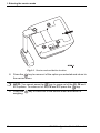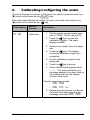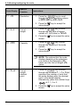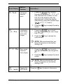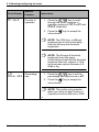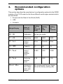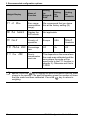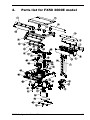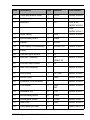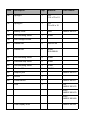
1
FX 50
Configuration Guide & Parts List
AWT35-000317 Issue AA
*AWT35-000317*
August 2007
© Avery Berkel Limited 2007. All rights reserved.
The information contained herein is the property of Avery Berkel Limited and is supplied without
liability for errors or omissions. No part may be reproduced or used except as authorised by
contract or other written permission. The copyright and the foregoing restriction on reproduction
and use extend to all media in which the information may be embodied.
Trademarks and ackowledgements
Avery, Avery Berkel and Avery Weigh-Tronix are registered trademarks in certain jurisdictions
and owned and registered by companies within the Avery Weigh-Tronix Group.
All brands and product names used within this document are trademarks or registered
trademarks of their respective holders.
IMPORTANT
When programming or configuring the equipment you must ensure that you comply with all
relevant standards and legislation. The example settings given in this book may not be legal for
trade with the public.
FX 50 Configuration Guide & Parts List
3
Thank you for choosing this Avery Berkel product.
Please read these safety and user instructions before you use this product.
Please read all the sections of this document that have Danger, Warning and
Caution symbols and notices.
W
WARNING! This is a Warning symbol. Warnings mean that failure
to follow specific practices and procedures may have major
consequences such as injury to personnel or serious corruption
to data or loss of data.
D
DANGER! This is a Danger symbol. Danger means that failure to
follow specific practices or procedures may result in an electrical
shock that could cause personal injury or death.
C
CAUTION! This is a Caution symbol. Cautions give information about
procedures that, if not observed, could result in damage to equipment
or corruption to and loss of data.
N
NOTE: This is a Note symbol. Notes give additional and important
information, hints and tips that help you to use your product.
FX 50 Configuration Guide & Parts List
5
Contents
Contents
1.
Entering the service mode
2.
Calibrating/configuring the scale
11
3.
Recommended configuration options
17
4.
Parts list for FX50 3000E model
19
FX 50 Configuration Guide & Parts List
9
7
1.
Entering the service mode
This section explains how to enter the service mode of the FX 50 scale so that
you can calibrate the scale or change its configuration.
N
NOTE: To calibrate or configure the scale you need to enter the
password number (0000) when the scale asks you so that the scale
allows you to access the functions and settings in the service menu.
To access the service menu do as follows:
1. Remove any items from the weigh pan.
2. Press the On switch
to turn the scale on.
3. While the scale is self-checking itself (that is, while all the numbers on
the three diplays count down from all nines to all zeros) press the
key. The weight display shows Pn which prompts you to enter the
password.
4. To enter the password, press the
display shows Pn----.
key four times (type 0000). The
5. Press the
key to accept the password. The display shows
CAL F0. This is the first option (F0) that you use the calibrate the
scale.
The service menu has 11 branches with Function (F) numbers. To scroll
through these options from F1 - F9 press the appropriate number key from
to select the option you want. If you want to select options F10 & F11
press the
key repeatedly as these are not available on the number
keys.
N
NOTE: The scale’s display shows the name of the option you selected
together with number of the option, such as F1, F2, and so on.
6. Press and release the service button on the underside of the scale.
N
NOTE: You will need to break the service seal to press the service
button.
7. Press the
key to enter an option.
FX 50 Configuration Guide & Parts List
9
1. Entering the service mode
Fig 1-1. Service seal and button location
8. Press the
key to come out of the option you selected and return to
the service menu.
N
NOTE: You cannot press the
key to come out of the F0, F8 and
F11 options. To come out of F0, F8 and F11 press the
key.
9. Press the
weighing.
10
key to come out of the service menu and return to
FX 50 Configuration Guide & Parts List
2.
Calibrating/configuring the scale
The scroll through the options in the menu you need to press the scroll key
(X) which is the same as the
key.
When the scale displays the option you want, press the select option key
(S) which is the same as the
key.
Scale Display
Name of
Function
F0
Calibration
CAL
Instructions
1. Set the gravity compensation zone
rate to 1.0000. This is option F11.
2. Press the
key to enter the
calibration function. The scale
displays unLoAd.
3. Remove any weight from the weigh
pan.
4. Press the
key. The display
shows the calibration weight you
requested.
5. Put the calibration weight on the
weigh pan.
6. Press the
key to accept.
7. Check that all three displays show
------. The scale calibrates, any
message appears for a short time on
the display and then the display
returns to the menu.
Possible messages include:
• SPan PASS
•
SPan
FAIL
Lo
8. Repeat the steps above to calibrate
the scale if the scale displays any
message other than SPAn PASS.
FX 50 Configuration Guide & Parts List
11
2. Calibrating/configuring the scale
Scale Display
Name of
Function
F1
Resolution
rES
Instructions
1. Press the
key to scroll
through the three resolution values
of 3000, 6000 or dUAL rAnGE.
2. Press the
key to accept the
value shown.
F2
Unit
Unit of
weight
1. Press the
key to scroll
through the two units of weight
options of KiLoS (kilos) or PoUndS.
2. Press the
shown.
F3
CAPA
Capacity
key to accept the value
1. Press the
key to scroll
through the capacity of the scale
options.
2. Press the
key to accept the
value shown.
N
F4
Point
Unit of
weight
decimal
point
NOTE: The options that the scale
displays depend on the selections
you made in the Resolution (F1)
option and the Unit of Weight (F2)
option.
1. Press the
key to scroll
through the numbers 0, 1, 2 or 3 that
represent the number of units that
the scale displays after the decimal
point in the weight display.
Alternatively, press the number keys
of 0, 1, 2 or 3.
2. Press the
shown.
12
key to accept the value
FX 50 Configuration Guide & Parts List
Scale Display
F5
Point
Name of
Function
Instructions
1. Press the
key to scroll
through the numbers 0, 1, 2, 3 or 4
that represent the number of units
that the scale displays after the
decimal point in the price display.
Alternatively, press the number keys
of 0, 1, 2, 3 and 4.
Unit price
decimal
point
2. Press the
shown.
F6
init
2Ero
1. Press the
key to scroll
through the initialization zero range
from 0 to 20.
Initialization
zero range
(auto zero
range)
2. Press the
key to accept the
value shown.
N
F7 re 2Ero
NOTE: We recommend that you
leave this function at the factory
setting of 4.
1. Press the
key to scroll
through the manual zero range 0 to
20.
Zero range
(manual
zero range)
2. Press the
shown.
N
F8
A-d
CoUntS
Display the
A/D counts
key to accept the value
NOTE: We recommend that you
leave this function at the factory
setting of 10.
Press the
FX 50 Configuration Guide & Parts List
key to accept the value
key to return to the menu.
13
2. Calibrating/configuring the scale
Scale Display
F9
CntrY
Name of
Function
Country of
operation
Instructions
1. Press the
key to scroll
through the three countries of
operation options of USA, EuroPE and
AUStra (Australia).
2. Press the
key to accept the
value shown.
F10
PErCnt tArE
Percentage
tare
N
NOTE: The USA has a different
keyboard layout and functionality
from the Europe and Australia
keyboards.
N
NOTE: The Europe & Australia
keyboards have the same
functionality except that the Australia
keyboard does not support a 100g /
kg price base options because it is
fixed in Kg.
1. Press the
key to set the
percentage tare option to on or oFF.
2. Press the
key to accept the
value shown.
N
14
NOTE: This option only operates
when you have set the Country of
Operation function (F9) set to USA.
FX 50 Configuration Guide & Parts List
Scale Display
Name of
Function
F11
Gru rATE
Gravity
compensation
zone rate
Instructions
You use this option to set the gravity
compensation zone rate when a scale is
calibrated outside of the intended gravity
zone of using the scale.
An example of setting this option is as
follows:
If we assume that the scale is calibrated in
Birmingham, UK where the gravity is
9.81287 and it will be used by a customer in
Denmark where the gravity is 9.81616.
1. Divide the intended customer
location of Denmark by the
calibration location of Birmingham
(9.81616 divided by 9.81287) to get
a result of 1.00034 (rounded to five
decimal places).
2. Enter the gravity compensation zone
rate of 1.00034 using the number
keys
.
3. Press the
key to accept the
value you entered.
4. If you do not need to enter a value
for the gravity compensation zone
rate (if the scale will be used at the
same location where it was
calibrated) set the rate to 1.0000.
N
NOTE: The number range is limited
to between 0.96000 and 1.04000.
You must do the calibration with the figure of
1.0000 and the gravity compensation zone
rate set afterwards. The scale does not
accept numbers entered outside of these
values. It displays, Err15 and return the
scale to the menu and defaults the rate to
1.0000. So you will have to re-enter the rate
if you need to change this figure.
FX 50 Configuration Guide & Parts List
15
3.
Recommended configuration
options
This section describes the manufacturer’s configuration options for the 3000E
models of the FX 50 scale for the three different world region variants which
are as follows:
• Europe and the Rest of the World (RoW)
• USA
• Australia.
Weight Display
Name of
Function
Setting
for
Europe &
RoW
F0
CAL
Calibration
Set as you prefer.
F1
rES
Resolution
3000
3000
3000
F2
Unit
Unit of
weight
Kilos
Pounds
Kilos
F3
CAPA
Capacity
15
30
15
F4
Point
Unit of
weight
decimal
point
0.000
0.00
0.000
F5
Point
Unit price
decimal
point
0.00
0.00
0.00
Initialization
We recommend that you leave
this at the factory setting (10).
F6init
2Ero
zero range
(auto zero
range)
FX 50 Configuration Guide & Parts List
Setting
for
USA
Setting
for
Australia
17
3. Recommended configuration options
Weight Display
F7
re
2Ero
F8
A-d
F9
CntrY
Name of
Function
Setting
for
Europe &
RoW
Setting
for
USA
Setting
for
Australia
Zero range
(manual zero
range)
We recommend that you leave
this at the factory setting (2).
Display the
A/D counts
Not applicable.
Country of
operation
Europe
USA
Austra
Australia
F10 PErCnt tArE
Percentage
tare
Off
On
Off
F11
Gravity
compensation
zone rate
This depends on the zone where
the scale was calibrated and the
zone where the scale will be
used (refer to the F11 function in
chapter 2). Otherwise set this to
1.0000.
N
18
Gru
CoUntS
rATE
NOTE: Press the
key to display the audit information that the scale
stores in its memory. The audit information gives the number of times
that the scale has been calibrated. Press the
key to return to
weighing.
FX 50 Configuration Guide & Parts List
4.
Parts list for FX50 3000E model
FX 50 Configuration Guide & Parts List
19
4. Parts list for FX50 3000E model
Item
Description
Qty.
Material
Part number
1
Front display overlay
1
PC
Euro
ABR97-001441
UK
ABR97-001442
USA
ABR97-001443
2
Weigh pan
1
SST304
ABR97-001444
3
Rubber boss
4
RUBBER
Black. Rigidity:
ABR97-001445
75°
4
Rear display overlay
1
PC
Euro
ABR97-001446
UK
ABR97-001447
USA
ABR97-001448
5
Tower display upper casing
1
6
Tower display PCB assembly
1
7
Tower display front overlay
1
ABS
ABR97-001449
ABR97-001450
PC
ABR97-001451
ABR97-001452
ABR97-001453
8
Tower display bottom casing
1
ABS
9
Self-threading screw
10
20Mn
10
Tower display rear overlay
1
PC
ABR97-001455
11
Tower pole
1
ABS
ABR97-001456
12
Tower pole
1
ABS
ABR97-001457
13
Tower pole bracket
1
ABS
ABR97-001458
20
ABR97-001454
FX 50 Configuration Guide & Parts List
Item
Description
Qty.
Material
Part number
14
Tower pole bracket cover
1
SPCC
ABR97-001459
15
Self-threading screw
2
20Mn
16
Keyboard
1
PC
Euro & UK
ABR97-001460
USA
ABR97-001461
17
Upper casing
1
ABS
18
Self-threading screw
4
20Mn
19
Washer
4
EDPM
20
Front display PCB assembly
1
20 mm LCD
21
Ferrite
1
22
Load cell upper bracket
1
Al
23
Load cell + brackets
1
Al
ZEMIC 6D
24
Load cell lower bracket
1
Al
25
Main PCB Assembly
1
26
Level bubble
1
14.7 mm
ABR97-001466
27
Bottom cover
1
ABS
ABR97-001467
28
Calibration PCB Assembly
1
29
Foot locknut
4
ABS
M8
ABR97-001469
30
Adjustable foot
4
PVC
ABR97-001470
31
Self-threading screw
6
20Mn
32
Rechargable battery
1
6V/4A
ABR97-001471
33
Seal cover
2
ABS
ABR97-001472
34
Easily-destroyed label
2
FX 50 Configuration Guide & Parts List
ABR97-001462
ABR97-001463
ABR97-001464
ABR97-001465
ABR97-001468
ABR97-001473
21
Item
Description
Qty.
Material
Part number
35
Sponge-I
1
CR
112 x 70 x 15
36
Sponge-II
1
CR
79 x 56 x 15
37
Battery cover
1
ABS
38
Self-threading screw
1
20Mn
39
Intel hexagon screw
4
40
Washer M6
4
HRC42-50
41
Washer M6
4
65Mn
200-300HV
42
Self-threading screw
4
20Mn
43
Overload stop screw
4
20Mn
44
Self-threading screw
3
20Mn
45
Washer M3
3
EDPM
46
Adaptor jack
1
47
Ferrite
1
48
Power switch
1
ABR97-001477
PSU
1
UK
ABR97-001478
ABR97-001474
ABR97-001475
Euro
ABR97-001479
Euro
ABR97-001480
Front display loom
ABR97-001481
Item
Description
Qty.
Material
Part number
Rear display looloom - mono
ABR97-001482
Rear display looloom - tower
ABR97-001483
FX 50 Configuration Guide & Parts List
23
This document contains a general guide only of the product and shall not form part of any contract unless
specifically agreed by Avery Berkel Limited in writing in each case on the Order Acknowledgement. The
specification of the products described herein may vary from time to time and may be altered without notice.
Avery Weight-Tronix is a trading name of Avery Berkel Limited.
USA
Avery Weigh-Tronix
1000 Armstrong Dr.
Fairmont MN 56031 USA
Tel: +1 507-238-4461
Fax: +1 507-238-4195
Email: [email protected]
Website: www.averyweigh-tronix.com
UK
Avery Weigh-Tronix
Foundry Lane, Smethwick
West Midlands, England B66 2LP
Tel: +44 (0)870 903 4343
Fax: +44 (0)121 224 8183
Email: [email protected]
Website: www.averyweigh-tronix.com