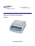
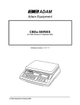
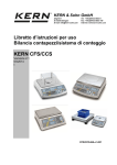
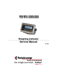
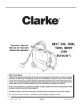
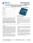
1
QHD series Counting Scale SERVICE MANUAL ©Intelligent Weighing Technology, Inc. 2012. All rights reserved worldwide. The information contained herein is the property of Intelligent Weighing Technology. and is supplied without liability for errors or omissions. No part may be reproduced or used except as authorized by contract or other written permission. The copyright and the foregoing restriction on reproduction and use extend to all media in which the information may be embodied. CONTENTS 1. PRECAUTIONS…… ………………………………………………………………..4 2. INSTALLATION……...…………..…………………….…………………………..…5 3. N AME AND FUNCTIONS…………….……………………………… …………7 Key board………………………………...................................................7 D i s p l a y… … … … … … … … … … … … … … … … … … … … … … … … … … … 8 4. O PERATION ………………………………………………………….………… 9 P o we r On /Of f …………………… .………………………………………… 9 Switch to local / Remote Scale….…....…………………………………. 9 Zero ……………………………….…………………………………………9 Tare……………………………………… …………………………………. 9 Accumulation …………………………………. ………………………….1 0 Manual Accumulation………………… …………………………………..1 0 Saved Data………………………………………………………………… 1 0 Delete Data……………… …………………………………………………1 0 Automatic Accumulation…………………………………………………..1 1 Parts Counting ………………………………………………………..…..1 1 Weighing a sample to determine the Unit Weight…………………….. 11 Enter a known Weight……………………………………………………..1 2 Automatic update of Unit Weight…………………………………………1 2 Check weighing of count pre-set…………………………………………12 Setting the checking limits………………………………………………..1 2 PLU (Product Look Up )………………………………………………….1 3 Storing PLU………………………………………………………………...1 3 Entering Description manually……………………………………………1 4 Recalling PLU……………………………………………………………...1 5 5. P ARAMETERS …………………………………………………………………1 6 Keys into the parameter…………………………………………………..1 6 Parameter settings………………………………………………………...1 7 6 . RS-232 OUT PUT………………………………………………………………18 7. CALIBRATION …………………………………………………………………21 8. TECHNICAL PAAMETER …………………………………………………….22 9 . ERROR DI SPLAY……………………………………………………………...2 4 10. TROUBLE SHOOTING…………………………………………………………25 -2 - 11. MAINTENANCE …………………………………………………………………27 Change Parts ………………………………………………………………..27 Replace main board…………………………………………………………2 7 Replace display board……………………………………………………....2 8 Re place load cell…………………………………………………………….2 8 Replace battery………………………………………………………………2 8 Checking Components ……………………………………………………2 9 Checking Load cell …………………………………………………………..2 9 Load cell connections……………………………………………………….2 9 Ch e ckin g vo lt a ge s…………………………………………………… … … 30 1 2 . CIRCUIT DIAGRAM……………………………………………………………..3 1 1 3 . DRAWING………………………………………………………………………... 3 3 Parts List………………………………………………………………………. 3 4 1 4 . SPECIFICATIONS………………………………………………………………..35 Specif ications………………………………………………………………….3 5 Specification for Remote scale ………………………………………… …..36 Specification for Local scale Load Cell……………………………………..36 -3- 1. PRECAUTIONS Read this manual before operating or servicing this equipment. Follow these instructions carefully. Disconnect this equipment from the power source before cleaning of performing maintenance. Keep the manual for your future reference. Avoid extremes of temperature. Do not place in direct sunlight or near air conditioning vents. Avoid unsuitable tables. The tables or floor must be rigid and not vibrate. Do not place near vibrating machinery. Avoid unstable power sources. Do not use near large users of electricity such as welding equipment or large motors. Avoid high humidity that might cause condensation. Avoid direct contact with water. Do not spray or immerse the scales in water. Avoid air movement such as from fans or opening doors. Do not place near open windows. Do not stack material on the scales when they are not in use. Keep the scales clean. -4 - 2. INSTALLATION Unpacking Carefully take the balance out of its package, make it sure its not damaged and all accessories are included. Accessories, 1. Balance 2. Adaptor 3. Stainless steel pan 4. Product manual Keep the packaging material for your future use. SETTINGS Local Scale: Place the scale on a table. Place the platform in the locating holes on the top cover. Do not press with excessive force as this could damage the load cell inside. Check the water mark. If, bubble is not centre adjust the leveling feet until reach centre. Check the level when you change the location. Attach the power supply cable to the connector on the right side of the scale base. Plug in the power supply module. Turn on the Scale. The power switch is located at the right side of the scale base. -5- The scale will be shown the model number in the “Weight” display and will be start self test. Remote Scale: The QHD+ Series can be connected to any size of load cell type weighing base through the Remote scale port on the left side of the scale case. Ensure you have the correct base for the scale as each is matched for calibration. Place the remote scale platform in the position where it is to be used. Level the scale by adjusting the four feet. If fitted with a spirit level then it should be adjusted such that the bubble is in the center. Press key to change remote mode and check weighing performance. Remote Scale Connection The cable of the load cell goes to a 9 pin DB9 d-subminiature plug connecter with following connections. Pin 1 and 2 4and 5 7 8 Connection Excitation+(5V) Excitation- (0v) SignalSignal+ Note: The sense wires connections of a six wire load cell are not used but can be connected to the respective Excitation pins. Remote Scale Setup The remote scale should set for a realistic resolution with respect to the input provided by the load cell/s. If a single 2mV/V load cell is fitted and more than 60% of the load cell is used for full capacity then the high output of >6mV span makes it possible to set a high resolution. If this criterion is met then the remote scale can be set to a high resolution with a maximum of 1/30,000, for example: 300kg x 10g. It will also be possible to sample on the remote scale with the same accuracy as the Local. Where more than one load cell is fitted or the total load cell capacity is not utilized then a reduced resolution should be selected in the remote scale technical set up. For example, if a system uses four 2mV/V 1000kg load cells for a scale of 1000kg capacity then the span output at full scale will be only 2.5mV. In this situation the resolution should be reduced to give a good number of ADC counts per displayed division, for example, set to 1:5000 or 1000kg x 0.2kg. -6 - Setting a high resolution without providing a good input to the remote scale ADC will not give better accuracy and may make the scale difficult to meet performance specification. For best performance ensure a minimum of 0.1uV/d. 3. NAME AND FUNCTIONS Key Board Keys to Press this key to Numeric Keys. Enter to individual unit weights and the present tare Clear incorrect entries and error conditions Decimal Point. Numeric input numbers select to the left. Returns the display to zero. Enter the clear tare weights, Storing the current weight as tare value. Subtracting the tare value from the total weight and displays the result as net weight. Manually enter the weight of sample, also changes the unit if they are enabled. Enter the numbers of items, used for the unit weight. Add the current count data aggregated. Also evokes the memory if pressed to balance empty. Can add up to 99 values, or until it reaches the maximum displayable digits Enter to store and recall the PLU To set the upper limit of the number of items counted and back light setting. To select the local or remote scale. -7- Display The arrow “▼”above the symbols Weight Display Low Battery Net Stable Zero Lb / kg Net Weight Display Stable Display Zeroing Display Current Weighing Mode Unit Weight Display Smpl U.Wt M+ Local / Remote No of samples is very low Unit weight is below the minimum weight Data entered into the memory Active Scale in use Count Display CkPcs Wt High OK Low Charge -8 - Active in Counting Mode Active in Weighing Mode Check Result above the high limit Check Result with in the limit Check Result below the low limit Status of the battery charging 4. OPERATION Initial Start-up Warm-up time of 15 minutes stabilizes the measured values after switching on. 1. Power ON/OFF Power switch is located below the right side of the scale. Switch on the scale by pressing on/off. The display is switched on and the self test is started. If you want to switch off press backward the key. 2. Switch to Local / Remote Scale By pressing the display changes from one to other scale. In Local Scale change Local In Remote Scale change remote The basic weighing functions are same for both the scales- local and remote. The number of weighing divisions may be less on the remote scale dependant on the total capacity of the load cell/s used. 3. Zero Environmental conditions can lead to the balance exactly zero in spite of the pan not taking any strain. However, you can set the display of your balance to zero any time by pressing ensure that the weighing starts at zero. key and therefore 4. Tare The weight of any container can be tared by pressing button so that with subsequent weighing the net weight of the object being weighed is always displayed. Load weight on the pan. Press key. Zero is displayed, and tare is subtracted. Remove weight from the platform. Tared weight is displayed. It can set only one tare value. It can display with a minus value. Press key. Zero is displayed, tare weight is cleared. Enter a tare value using by numeric keys. This method allows you to enter a value for the tare weight from the keypad. This is useful if all containers are the same or if the container is already full but the net weight is required and the weight of the container is -9- known. Ensure display is in zero. Enter the known tare weight by using numeric keys. Press to enter, weight will be stored as tare weight and displayed with minus sign and net indicator. Place the container on the platform, net weight will be displayed. The tare will be rounded up according to the readability of the balance. For example, if a tare value of 103g is entered into the 60Kg scale with 5g readability, then the display will be shown -105g. 5. Accumulation The balance can totalize weight values or count quantities. Manual Accumulation The values (weight and count) shown on display can be add to the memory by pressing key. Set the parameter F1 off – print – au off Place the goods to be weighed. 0 .5 00 0 0 Wait few seconds for display stability then press . The weight display will be show the total weight, the unit weight display will be show the number of items and count display will be show the total accumulated count. The values will be displayed 2 seconds. 0 .5 00 1 15 The scale must return to come zero or negative number before adding another samples. More products can be added by pressing . It can add up to 99 entries or until the capacity of the weight display is exceeded. Display of Saved Data To check the total value saved, press key when the display is in zero. Total weight will be displayed two seconds. Delete Saved Data To clear the memory, press the display will be shown saved data. 1 .5 00 - 10 - - 3 - 0 Press during the display, delete all saved accumulation data. 0 00 - 0 - 0 Automatic Accumulation Weighing values automatically accumulate total, when the goods is unloaded and with out key pressing. Set the parameter F1 off – print – au on Place the goods on the platform 1 .5 00 0 0 Wait few seconds for display stability and a control beep. Unload the goods from the platform, the weighing value is added into the memory 1 .5 00 - 10 The scale must return to come zero or negative number before adding another samples. It can add up to 99 entries or until the capacity of the weight display is exceeded. 6. Parts Counting In order to do parts counting, it is necessary to know the average weight of the items to be counted. This can be done either by weighing a known number of the items and letting the scale determine the average unit weight or by manually inputting a known unit weight using the keypad. To count a greater number of parts the average weight per part has to be determined with a small quantity. The average piece weight can be increased at any time during the counting process, by entering the displayed number of items and confirming by pressing . Weighing a sample to determine the Unit Weight Reset the balance to zero or tare the empty container if necessary. Place the known quantity of items on the scale, wait few seconds for display stable. Enter the number of quantity by using numeric keys. Eg: 15 1 .5 00 15 0 - 11 - Enter the key to confirm. The scale determines the average parts weight. 1 .5 00 0 .15 10 As more items are added to the scale, the weight and the count will increase. If the scale is not stable, the calculation will not be completed. If the weight is below zero, “Count” display will show negative count. Enter a known Unit Weight If already know the unit weight, and then it can enter by using numeric keys. Enter the value of unit weight by numeric keys. Press during the unit display flashing. If in the weight display as “kg” unit is active, the average piece weight will be displayed in “g”. If as “lb” is active, the average piece weight will be displayed in “lb”. Automatic Update of Unit Weight The scale can automatically update the unit weight, when a sample less than the initial sample count are added. A beep will be heard when the value has updated. By pressing key, can be blocked unit weight and auto update Check Weighing or Count Pre-set Check weighing is a procedure to cause an alarm to sound when the weight or piece quantity within the checking limits. Limits can beset by using numeric keys. Setting the Checking Limits Press key, the active mode will be shown Pst Press key to select counting Pst Press cnt key, the active high count limit will be shown Hi cmt - 12 - net 1 500 Use numeric key to enter desired and if necessary press Press to clear. key, the active low count limit will be shown lo cmt 500 Use numeric key to enter desired and if necessary press Press to clear. key to return weighing mode. For check limits, just one limit value can set If both values are deleted, the check mode is deactivated. The beep sound will be worked as described in the beep parameter f1 off , beep PLU (Product Look Up) PLU are used to store items. It can store up to 99 PLU numbers. These data should be entered against a particular PLU before the weighing process starts, so that the desired PLU’s can be recalled during the weighing process. The data can be stored and recalled manually or by sending data over RS-232 Interface Storing PLU Press key to ensure display zero. Tare and unit weight to be stored can be either taken from a weighing in process or by enter manually. Press display will be shown P lu - - P lu 27 Press numeric key 2 and 7 Press Currently stored text will appear The first digit is flashing, it can Change by using numeric keys If necessary, delete additional text P lu 27 Apple P lu 27 - 13 - By pressing Continue to enter text until description is complete (max: 12 characters) P lu 27 Use Use abcdefg hijklmn key, number selection to left. key, number selection to right. Press and hold two seconds key, space to right. Tare values can be saved when in the admitted taring range(default >2% of capacity) Entering Description Manually To set the description, press the numeric button and keep it pressed until the desired letter is displayed. The characters are according to key board. 1 2 -/\ ABC 3 4 5 6 7 8 9 0 DEF GHI JKL MNO PQRS TUV WXYZ _[] _ (space) The characters and the displayed symbols are A B C D E F G H I J K L M N O P Q R S T U V WX Y Z A B C D E F G H I J K L M N O P Q R S T U V W X Y Z / \ ( ) 1 2 3 4 5 6 7 8 9 0 1 2 3 4 5 6 7 8 9 0 Note that this method is only used where alpha-numeric data is permitted. This is used for the Description field and the User ID number, Scale ID number in the parameters section. - 14 - Recalling PLU To recall the PLU values the user should first select either local or remote scale the tare value stored will be specific to the scale selected. Press display will be shown P lu - - P lu 27 Press numeric key 2 and 7 Press P lu 27 Abcdefg hijkllm PLU’s can be stored and recalled using RS-232 Interface. - 15 - 5. PARAMETERS Enter into the Parameter Turn on the scale, press during that start up. Display will be shown F1 off Select the Menu Block Press key, it can choose menu block one by one. Enter the Selected Menu Press key, it can confirm which will be shown displayed. Select the Sub- Menu Press key, it can choose the sub-menu block one by one. Return to Weighing Mode Press - 16 - key, it can escape from the menu and exit to weighing mode. Parameter Setting Menu Sub Menu Beep Beep off Beep On in Fi off Beep On out El F2 prt Lite aut Lite off Lite on unit Kg / lb Kilo lb Off 0 3 5 15 3 0 P mode Print Au on Au off U id U id P cont Ser re B 600 B 1200 B 2400 B 4800 B 9600 8 n 1 7 e 1 7 o 1 Tpup Lp50 abcdef Sc id Sc id abcdef P baud parity P type Tech Description Beeper is turned off Beeper is turned on, will be sounded with in the check weighing limits Beeper will be sounded above the check weighing limits Backlight will be turn on automatically, when loaded or key is pressed Backlight is turned off Back light is turned on Weighing Unit kg and lb are enable Weighing Unit kg only Weighing Unit lb only Auto off function disable Scale will be off three minutes later Scale will be off five minutes later Scale will be off 15 minutes later Scale will be off 30 minutes later Data out put / accumulation after unloading the balance Data out put / accumulation after by pressing RS 232 data output continuously RS 232 data output weight only Set the required baud 8 bits, no parity 7 bits, even parity 7 bits, no parity Standard printer setting Tscale Label Printer Shows the current User ID (max 6 characters) Shows the current Scale ID (max 6 characters) Technical parameter password protected - 17 - 6. RS- 232 OUT PUT The QHD Series of scales can be ordered with an option RS-232 output. Specifications: RS-232 output of weighing data ASCII code 4800 Baud 8 data bits No Parity Connector: 9 pin socket Pin 2 Output Pin 3 Input Pin 5 Signal Ground Sample of out put LOCAL SCALE ID: 123ABC NAME:Text 12.456 kg NET 1.1234 g U.W. 11 PCS TOTAL -- --- --- --- 49.824 kg TW 44 TPC 4 No. Control Commands - 18 - The scale can be controlled with following commands. Basic Commands: PLUxx T T123.456 Z P M+ MR MC U123.456 S123 SL SR Select PLU from scale memory Tare current weight value Numeric tare value Zero Print Store and print current results Recall memory values to scale display Clear memory Store unit weight of 123.456 kg / lb Enter sample size of parts 123 . Same as pressing Select local scale to be used Select remote scale to be used Printing Commands: \L \I \S \N \G \T \U \P \C \W \M \B Scale: Local or Remote User ID number Scale ID number Net weight Gross Weight Tare weight Unit weight Count Total Count Total Weight Number of items stored in memory A blank / space line PLU entry using RS 232 interface This will allow the scale data to be sent from a PC program as well as from the keypad. The most common PLUs can be stored and recalled from the scale memory. Other PLU data can be stored on a PC, then the text data, unit weight and tare data can be sent from the PC to PLU00. This can then be used and over written each operation. OPERATION: Send tare data to set any tare value to be stored with PLU. i.e. “T0.150” <CR>. If no tare is needed then you may send T0 to delete any present tare data. Send the unit weight to be stored with PLU. ie. “U12.3456” <CR> - 19 - Send PLU text data to be stored with current TARE and U/W values. ie. “SPLU01,Parts” <CR> - 20 - 7. CALIBRATION Turn on the scale and press during the self test. Pi n Use the numeric key to enter password Default password 0000 Press Pi n to confirm Display will be shown tech Select Local or Remote scale by pressing Press Local remote to confirm. Display will be shown If necessary, press Press - - - - tech unit to select the weighing unit kg or lb. to confirm. Display will be shown unload Ensure the platform is empty and wait for stable indicator. Press to confirm. Display will be shown sel Set weight value will be required Enter the value by using numeric keys Press 000000 000005 to confirm. Display will be shown Load Place the calibration weight on the platform and wait few seconds for display stable. Press to confirm. After the calibration scale will start a self test, remove the weight during that time and display will return to weighing mode. Incase display will show any error message or incorrect measurement, repeat the calibration again. - 21 - 8. TECHNICAL PARAMETER Enter into the parameter by pressing during the self test Press until tech is displayed F1 off tech Pi n Press to confirm, display will be shown Enter the password. Default password is 0000 Pi n and press to confirm Select the scale by pressing should be configured and press Use the , which key to select the weighing unit to confirm key to scroll to select individual Confirm selected menu by pressing Press key, escape from the menu and exit to weighing mode - 22 - Tech local remote to confirm kg / lb and press Use the menu. - - - - Tech cnt unit Technical Parameter Sub Menu Cnt Cap Internal counts Capacity ( For Remote Scale Only ) desc 0 Set remote scale 0.0 decimal point 0.00 0.000 Sel 001000 Set remote scale capacity by using numeric keys I nc 1 Set remote scale division 2 5 10 20 50 I nc 5 Set division I nc 10 I nc 20 I nc 50 Azn 0 .5d Automatic zero tracking Azn 1d Azn 2d Azn 4d 0 auto 0 Zero setting range, after 0 auto 2 switching on the scales 0 auto 5 to zero 0 auto 10 0 auto 20 0 manl 0 Zero setting range, the 0 manl 2 display is set to zero by 0 manl 4 pressing 0 manl 10 0 manl 50 0 manl 100 Pi n 1 Enter new password Pi n 2 Re enter new password 9. 673 00 Set local gravity Di v A 2t 0 Auto 0 manl Pi n Gra Description - 23 - 9. ERROR DISPLAY Error Message ----Err 1 Err 2 Err 4 Err 5 Err 6 Err 9 Description Solution Maximum load exceeded Unload or reduce weight Incorrect date Enter the date by using format “yy;mm:dd” Incorrect time Enter the time by using format “hh:mm:ss” Zero setting error Zero setting range exceeded due to switching on.(4%max) Make sure platform empty. Key board error Check the keys and connecter. A/D value out of range Make sure platform empty and check the pan is installed proper. Check the load cell connectors. Unstable Reading Check any air variation, vibration, RF noise and touching some where. Check the load cell and connecters. Err 17 Tare out of range --ol-- Over range Fai l h / fai l l Err p Ba lo / lo ba Calibration Error - 24 - Printer error Battery low Remove the load and restart scale again. Remove the load. Re calibrate Re calibrate Check the printer and settings Re charge battery, check the voltages. 10. TROUBLE SHOOTING No Display: Mains power is turned off or power supply not plugged proper. Power supply faulty. Internal Battery is not charged. Check On/OFF switch is turned on and faulty or not. Check the PCB power connecters and cable. Display is Blank after the self test / Err stuck: Unstable weight. Check the platform is installed correctly. Try again to turning on. Check the load cell is not touching any where. Load cell is damaged. Check the load cell connections and all. OL or( -------) appear the display: Maximum capacity exceeded. Power supply faulty. Check all power cables and connecters. Calibrate again with correct calibration weights. Load cell damaged. Check load cell connections. (------) or Lo: Weight is below permissible limit. Check the pan installed correctly. Calibrate again with correct calibration weights. Power Supply faulty. Check all power cables and connecters. Load cell damaged. Check load cell connections and connecters. Try to turn on again. Unstable display: Check the pan is seated proper and touching some where Check any vibrations, noises, sudden temperature changes. Check power supply. - 25 - Check battery and connect to charging. Check the load weight is seated properly. Check the load cell connections and connecters. Incorrect value: Calibration error. Calibrate again with exact calibration mass weights. Check the weight sample is lying proper and avoids touching the cover or surface. Check power supply and battery. Check load cell connections and connectors. Can not use scale full capacity: Before weighing make sure zero indication is showing and scale is empty. Check the weighing mode. Check the load cell is fitted proper and touching housing or hitting somewhere. Calibrate again with exact calibration mass weights. Load cell damaged. Check load cell connections and connectors. Main PCB problem. Battery not charging: Mains voltage problem. Check the power supply voltage and adaptor voltage. Charging circuit failure. Battery failure, check the battery connections - 26 - 11. MAINTENANCE Disconnect the power before cleaning. Use a cloth with mild suds and light cleaning agents. Make sure that fluid is not able to get into the device. Use a clean and soft cloth for remove. This devise does not require any routine maintenance. It may be necessary to perform periodic checks of the calibration of the scale due to mechanical reasons. The frequency of the checks depends on the conditions to use. CHANGE PARTS 1. Replace main board Remove adaptor pin from the jack. Remove the pan. Remove the five screws from the bottom of housing, securing the front and back halves of the cover. Disconnect the power connector, display connector and load cell cable. Disconnect the ground cable from the main PCB Remove the main PCB from the back cover. Carefully remove the main PCB and keep on a protective place. Install a new main PCB. Connect load cell cable, display connector, ground cable and power connecter. Close the top cover to the bottom cover with the five screws. - 27 - 2. Replace display board Remove the top cover Remove the seven screws from the display board and clean the glue. Disconnect the key board connecter and main PCB connecter from the display board. Remove the display board. Install a new display board. Connect the key board connecter and main PCB connecter. Turn on the power and check the working condition. Then, turn off the power. Fix the seven screws and apply glue. Close the top cover. 3. Replace load cell with load cell from Bracket set place on Remove the allen and bottom brackets key. Load cell will get bracket. Install the new load Open the top cover. If necessary remove the PCB’s for avoid damage. Disconnect load cell connections from the PCB. Remove the four foots from the bottom cover. Remove the four screws from the upper bracket. Remove the bracket the cover. the table. screws from the top by using 5mm allen separate from the cell. Fix the brackets proper. Fix whole bracket to the bottom cover by using four screws. Fix the four foots to the bottom cover. Connect the load cell connections to the main PCB. Fix all PCB’s and cables proper. Close the top cover. 4. Replace battery Remove the pan and dust cover. Open the battery cover from the top cover. - 28 - Take it out the battery from in side the housing. Remove the connecters from the battery terminals. Change the new battery. Connect the connecters to the battery terminals. Battery, place it proper to inside the housing. Close the battery cover. Fix the dust cover and pan. Checking Components Remove the pan Open the housing. Make sure components all are clean. Check the connectors are connected proper. Check the keyboard. Check the display board and main PCB. Check the load cell Check the battery If any component damaged replace it. Close the housing. Install the pan and check its lying proper there. Checking Load cell Remove the top cover from the scale. Remove power connecter from the main board. Make sure load cell cable connections are proper and no insulation material is touching the terminal contacts. Check load cell bridge resistance. Load Cell Connections: Signal + Supply + Green Red Signal - White Supply - Black - 29 - Shield Points Resistance Red (+E) to Black (-E) 406 ohms ± 6 ohms Green (+S) to White (-S) 350 ohms ± 3 ohms If proper excitation voltage is reaching the load cell, check the output signal. If load cell has an unusual signal, replace that load cell. Checking Voltages - 30 - Using a multimeter, check the mains voltage. Check the adaptor is outputting a voltage 9 VDC. Check PCB input voltage 9VDC. Check battery voltage of at least 6 VDC. 12. CIRCUIT DIAGRAM - 31 - - 32 - 13. DRAWING - 33 - Parts List No 1 2 3 4 5 6 7 8 9 10 11 12 13 14 15 16 17 18 19 20 21 22 23 24 25 26 27 28 29 30 31 32 33 34 35 36 37 - 34 - Parts Name Pan Pan Battery cover Battery Foam Rear Overlay Top Cover Name Plate Internal Allen Screw Washer (M6) Spring Washer(M6) Load cell upper bracket Load cell Star (+) Screw Load cell lower bracket Self thread Screw Insulative Washer Power Socket Power Socket Spacer Power Switch Foot Key board Front display overlay Level bubble Screw Front Display PCBA Insulative Washer Star (+) Self thread screw Star (+) Self thread screw Hexagon Nut Main PCBA Screw for D connector D type connector Hexagon nut for D connector Overlay Bottom Cover Self thread screw Qty 1 1 1 1 1 1 1 1 4 4 4 1 1 4 1 4 4 1 1 1 4 1 1 1 1 1 5 5 5 4 1 4 2 4 1 1 5 Material SST ABS ABS Lead Acid CR Spec 230mmx300mm 230mmx300mm 6V/4Ah ABS 65Mn M6x16, 8.8 200-300HV HRC42-50 Aluminum Aluminum Alloy 20Mn M4x16 Aluminum S18C 4x10 EDPM 8x3.1x1.2t PC PVC 14.7mm M4x35 EDPM 20Mn 20Mn 20Mn 8x3.1x1.2t M3x20 M4x20 Zn Coating ABS 4x12 14. SPECIFICATIONS DIMENSION Specification MODEL Maximum Capacity Readability Tare Range Repeatability(Std Dev) Linearity ± Units of Measure Interface Stabilization Time Operating Temperature Power supply Calibration Display Housing Indicator Pan size Overall dimensions Net weight Applications Internal Resolution QHD+ 3 3000 g 0.05 g -3 kg 0.05 g 0.1 g QHD+ 6 6000 g 0.1 g -6 kg 0.1 g 0.2 g QHD+ 15 QHD+ 30 15 kg 30 kg 0.2 g 0.5 g -10 kg -30 kg 0.2 g 0.5 g 0.5 g 1g lb, kg Bi-directional RS-232 Interface 2 Seconds 0°C - 40°C (32°F - 104°F) AC Adaptor 9 V/800 mA / Battery 6V4AH Automatic external 3 x 6 digits LCD digital display with white LED back light ABS Plastic, Stainless Steel pan 225 x 300mm / 8.9 x 11.8” 320 x 340 x 125mm / 12.6 x 13.4 x 4.9” 4.3kg / 9.5lb Counting Scale Up to60000 - 35 - Specification for Remote Scale Excitation voltage Signal range Zero range Sensitivity Internal ADC counts Load Connection Maximum cable length Termination 5 VDC 0-20 mV(allows 3 mV/V LC with 5mv zero offset) 0-5 mV 0.02 µV/internal ADC count or better 500,000 maximum at 10 mV input 87 ohm minimum, 4 X 350 ohm load cells 4 wire connection to load cells plus shield 6 meters 9 pin d-subminiature plug on scale Specification for Local Scale Load Cell Model No Rated Capacity Rated Out put Excitation Voltage IP Level Material Cable Input Resistance Out put Resistance Temperature Range Safe overload Ultimate overload Repeatability Creep Zero Balance - 36 - C2X1 6~50 (kg) 2.0 mV/V±0.2 mV/V 20 VDC IP64 Aluminum Alloy Φ8.2 four core shield 420Ω±30Ω 350 Ω± 5 Ω -10°C - 50°C 150 %R.C 200 %R.C 0.02 %R.O 0.02 %R.O/ 20min ± 0.1 mV/V Intelligent Weighing Technology has more than 50 years experience in the weighing industry, both in the USA and worldwide. With contacts in over 50 countries including the USA, we provide you with the weighing equipment you need. When you invest in weighing equipment from Intelligent Weighing Technology, you’re really buying peace of mind. Quality - Scales and balances solidly built from the ground up with superior engineering and components for exacting results. Value - From bench scales to analytical balances, weighing equipment priced for real-world business applications, with superior service and support. Experience - Expert advice to help you choose just the right product for your application. Quality + Value + Experience…it adds up to the Intelligent Investment. Intelligent Weighing Technology, Inc. www.intelligentwt.com - 37 -