1
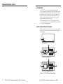
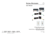
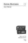
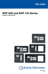
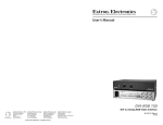
User’s Guide
PS 123
www.extron.com
Extron Electronics, USA
1230 South Lewis Street
Anaheim, CA 92805
800.633.9876 714.491.1500
FAX 714.491.1517
Extron Electronics, Europe
Beeldschermweg 6C
3821 AH Amersfoort, The Netherlands
+800.3987.6673 +31.33.453.4040
FAX +31.33.453.4050
Extron Electronics, Asia
135 Joo Seng Rd. #04-01
PM Industrial Bldg., Singapore 368363
+800.7339.8766 +65.6383.4400
FAX +65.6383.4664
© 2007 Extron Electronics. All rights reserved.
Extron Electronics, Japan
Kyodo Building, 16 Ichibancho
Chiyoda-ku, Tokyo 102-0082
Japan
+81.3.3511.7655 FAX +81.3.3511.7656
12 VDC, 3 Amp Power Supply
68-1253-01 Rev. C
07 07
Precautions
Safety Instructions • English
This symbol is intended to alert the user of important
operating and maintenance (servicing) instructions in
the literature provided with the equipment.
This symbol is intended to alert the user of the
presence of uninsulated dangerous voltage within
the product’s enclosure that may present a risk of
electric shock.
Caution
Read Instructions • Read and understand all safety and operating
instructions before using the equipment.
Retain Instructions • The safety instructions should be kept for future
reference.
Follow Warnings • Follow all warnings and instructions marked on the
equipment or in the user information.
Avoid Attachments • Do not use tools or attachments that are not
recommended by the equipment manufacturer because they may be
hazardous.
Consignes de Sécurité • Français
Ce symbole sert à avertir l’utilisateur que la
documentation fournie avec le matériel contient des
instructions importantes concernant l’exploitation et
la maintenance (réparation).
Ce symbole sert à avertir l’utilisateur de la présence
dans le boîtier de l’appareil de tensions dangereuses
non isolées posant des risques d’électrocution.
Attention
Lire les instructions• Prendre connaissance de toutes les consignes de
sécurité et d’exploitation avant d’utiliser le matériel.
Conserver les instructions• Ranger les consignes de sécurité afin de pouvoir
les consulter à l’avenir.
Respecter les avertissements • Observer tous les avertissements et consignes
marqués sur le matériel ou présentés dans la documentation utilisateur.
Eviter les pièces de fixation • Ne pas utiliser de pièces de fixation ni d’outils
non recommandés par le fabricant du matériel car cela risquerait de poser
certains dangers.
Sicherheitsanleitungen • Deutsch
Dieses Symbol soll dem Benutzer in der im
Lieferumfang enthaltenen Dokumentation
besonders wichtige Hinweise zur Bedienung und
Wartung (Instandhaltung) geben.
Dieses Symbol soll den Benutzer darauf aufmerksam
machen, daß im Inneren des Gehäuses dieses
Produktes gefährliche Spannungen, die nicht isoliert
sind und die einen elektrischen Schock verursachen
können, herrschen.
Achtung
Lesen der Anleitungen • Bevor Sie das Gerät zum ersten Mal verwenden,
sollten Sie alle Sicherheits-und Bedienungsanleitungen genau durchlesen
und verstehen.
Aufbewahren der Anleitungen • Die Hinweise zur elektrischen Sicherheit
des Produktes sollten Sie aufbewahren, damit Sie im Bedarfsfall darauf
zurückgreifen können.
Befolgen der Warnhinweise • Befolgen Sie alle Warnhinweise und
Anleitungen auf dem Gerät oder in der Benutzerdokumentation.
Keine Zusatzgeräte • Verwenden Sie keine Werkzeuge oder Zusatzgeräte,
die nicht ausdrücklich vom Hersteller empfohlen wurden, da diese eine
Gefahrenquelle darstellen können.
Instrucciones de seguridad • Español
Este símbolo se utiliza para advertir al usuario
sobre instrucciones importantes de operación y
mantenimiento (o cambio de partes) que se desean
destacar en el contenido de la documentación
suministrada con los equipos.
Este símbolo se utiliza para advertir al usuario sobre
la presencia de elementos con voltaje peligroso sin
protección aislante, que puedan encontrarse dentro
de la caja o alojamiento del producto, y que puedan
representar riesgo de electrocución.
Precaucion
Leer las instrucciones • Leer y analizar todas las instrucciones de operación y
seguridad, antes de usar el equipo.
Conservar las instrucciones • Conservar las instrucciones de seguridad para
futura consulta.
Obedecer las advertencias • Todas las advertencias e instrucciones marcadas
en el equipo o en la documentación del usuario, deben ser obedecidas.
Evitar el uso de accesorios • No usar herramientas o accesorios que no
sean especificamente recomendados por el fabricante, ya que podrian
implicar riesgos.
Extron’s Warranty
Warning
Power sources • This equipment should be operated only from the power source
indicated on the product. This equipment is intended to be used with a main power
system with a grounded (neutral) conductor. The third (grounding) pin is a safety
feature, do not attempt to bypass or disable it.
Power disconnection • To remove power from the equipment safely, remove all power
cords from the rear of the equipment, or the desktop power module (if detachable),
or from the power source receptacle (wall plug).
Power cord protection • Power cords should be routed so that they are not likely to be
stepped on or pinched by items placed upon or against them.
Servicing • Refer all servicing to qualified service personnel. There are no userserviceable parts inside. To prevent the risk of shock, do not attempt to service
this equipment yourself because opening or removing covers may expose you to
dangerous voltage or other hazards.
Slots and openings • If the equipment has slots or holes in the enclosure, these are
provided to prevent overheating of sensitive components inside. These openings
must never be blocked by other objects.
Lithium battery • There is a danger of explosion if battery is incorrectly
replaced. Replace it only with the same or equivalent type recommended by
the manufacturer. Dispose of used batteries according to the manufacturer’s
instructions.
Avertissement
Alimentations• Ne faire fonctionner ce matériel qu’avec la source d’alimentation
indiquée sur l’appareil. Ce matériel doit être utilisé avec une alimentation principale
comportant un fil de terre (neutre). Le troisième contact (de mise à la terre) constitue
un dispositif de sécurité : n’essayez pas de la contourner ni de la désactiver.
Déconnexion de l’alimentation• Pour mettre le matériel hors tension sans danger,
déconnectez tous les cordons d’alimentation de l’arrière de l’appareil ou du module
d’alimentation de bureau (s’il est amovible) ou encore de la prise secteur.
Protection du cordon d’alimentation • Acheminer les cordons d’alimentation de
manière à ce que personne ne risque de marcher dessus et à ce qu’ils ne soient pas
écrasés ou pincés par des objets.
Réparation-maintenance • Faire exécuter toutes les interventions de réparationmaintenance par un technicien qualifié. Aucun des éléments internes ne peut être
réparé par l’utilisateur. Afin d’éviter tout danger d’électrocution, l’utilisateur ne doit
pas essayer de procéder lui-même à ces opérations car l’ouverture ou le retrait des
couvercles risquent de l’exposer à de hautes tensions et autres dangers.
Fentes et orifices • Si le boîtier de l’appareil comporte des fentes ou des orifices, ceux-ci
servent à empêcher les composants internes sensibles de surchauffer. Ces ouvertures
ne doivent jamais être bloquées par des objets.
Lithium Batterie • Il a danger d’explosion s’ll y a remplacment incorrect de la batterie.
Remplacer uniquement avec une batterie du meme type ou d’un ype equivalent
recommande par le constructeur. Mettre au reut les batteries usagees conformement
aux instructions du fabricant.
Vorsicht
Stromquellen • Dieses Gerät sollte nur über die auf dem Produkt angegebene
Stromquelle betrieben werden. Dieses Gerät wurde für eine Verwendung mit einer
Hauptstromleitung mit einem geerdeten (neutralen) Leiter konzipiert. Der dritte
Kontakt ist für einen Erdanschluß, und stellt eine Sicherheitsfunktion dar. Diese
sollte nicht umgangen oder außer Betrieb gesetzt werden.
Stromunterbrechung • Um das Gerät auf sichere Weise vom Netz zu trennen, sollten
Sie alle Netzkabel aus der Rückseite des Gerätes, aus der externen Stomversorgung
(falls dies möglich ist) oder aus der Wandsteckdose ziehen.
Schutz des Netzkabels • Netzkabel sollten stets so verlegt werden, daß sie nicht im
Weg liegen und niemand darauf treten kann oder Objekte darauf- oder unmittelbar
dagegengestellt werden können.
Wartung • Alle Wartungsmaßnahmen sollten nur von qualifiziertem Servicepersonal
durchgeführt werden. Die internen Komponenten des Gerätes sind wartungsfrei.
Zur Vermeidung eines elektrischen Schocks versuchen Sie in keinem Fall, dieses
Gerät selbst öffnen, da beim Entfernen der Abdeckungen die Gefahr eines
elektrischen Schlags und/oder andere Gefahren bestehen.
Schlitze und Öffnungen • Wenn das Gerät Schlitze oder Löcher im Gehäuse aufweist,
dienen diese zur Vermeidung einer Überhitzung der empfindlichen Teile im
Inneren. Diese Öffnungen dürfen niemals von anderen Objekten blockiert werden.
Litium-Batterie • Explosionsgefahr, falls die Batterie nicht richtig ersetzt
wird. Ersetzen Sie verbrauchte Batterien nur durch den gleichen oder einen
vergleichbaren Batterietyp, der auch vom Hersteller empfohlen wird. Entsorgen Sie
verbrauchte Batterien bitte gemäß den Herstelleranweisungen.
Advertencia
Alimentación eléctrica • Este equipo debe conectarse únicamente a la fuente/tipo
de alimentación eléctrica indicada en el mismo. La alimentación eléctrica de este
equipo debe provenir de un sistema de distribución general con conductor neutro
a tierra. La tercera pata (puesta a tierra) es una medida de seguridad, no puentearia
ni eliminaria.
Desconexión de alimentación eléctrica • Para desconectar con seguridad la acometida
de alimentación eléctrica al equipo, desenchufar todos los cables de alimentación
en el panel trasero del equipo, o desenchufar el módulo de alimentación (si fuera
independiente), o desenchufar el cable del receptáculo de la pared.
Protección del cables de alimentación • Los cables de alimentación eléctrica se deben
instalar en lugares donde no sean pisados ni apretados por objetos que se puedan
apoyar sobre ellos.
Reparaciones/mantenimiento • Solicitar siempre los servicios técnicos de personal
calificado. En el interior no hay partes a las que el usuario deba acceder. Para evitar
riesgo de electrocución, no intentar personalmente la reparación/mantenimiento
de este equipo, ya que al abrir o extraer las tapas puede quedar expuesto a voltajes
peligrosos u otros riesgos.
Ranuras y aberturas • Si el equipo posee ranuras o orificios en su caja/alojamiento,
es para evitar el sobrecalientamiento de componentes internos sensibles. Estas
aberturas nunca se deben obstruir con otros objetos.
Batería de litio • Existe riesgo de explosión si esta batería se coloca en la posición
incorrecta. Cambiar esta batería únicamente con el mismo tipo (o su equivalente)
recomendado por el fabricante. Desachar las baterías usadas siguiendo las
instrucciones del fabricante.
Extron Electronics warrants this product against defects in materials and workmanship
for a period of three years from the date of purchase. In the event of malfunction during
the warranty period attributable directly to faulty workmanship and/or materials,
Extron Electronics will, at its option, repair or replace said products or components,
to whatever extent it shall deem necessary to restore said product to proper operating
condition, provided that it is returned within the warranty period, with proof of
purchase and description of malfunction to:
USA, Canada, South America,
and Central America:
Extron Electronics 1001 East Ball Road
Anaheim, CA 92805, USA
Asia:
Extron Electronics, Asia
135 Joo Seng Road, #04-01
PM Industrial Bldg.
Singapore 368363
Europe, Africa, and the Middle East:
Extron Electronics, Europe
Beeldschermweg 6C
3821 AH Amersfoort
The Netherlands
Japan:
Extron Electronics, Japan
Kyodo Building
16 Ichibancho
Chiyoda-ku, Tokyo 102-0082
Japan
This Limited Warranty does not apply if the fault has been caused by misuse, improper
handling care, electrical or mechanical abuse, abnormal operating conditions or nonExtron authorized modification to the product.
If it has been determined that the product is defective, please call Extron and ask for an
Applications Engineer at (714) 491-1500 (USA), 31.33.453.4040 (Europe), 65.6383.4400
(Asia), or 81.3.3511.7655 (Japan) to receive an RA# (Return Authorization number). This
will begin the repair process as quickly as possible.
Units must be returned insured, with shipping charges prepaid. If not insured, you
assume the risk of loss or damage during shipment. Returned units must include the
serial number and a description of the problem, as well as the name of the person to
contact in case there are any questions.
Extron Electronics makes no further warranties either expressed or implied with respect
to the product and its quality, performance, merchantability, or fitness for any particular
use. In no event will Extron Electronics be liable for direct, indirect, or consequential
damages resulting from any defect in this product even if Extron Electronics has been
advised of such damage.
Please note that laws vary from state to state and country to country, and that some
provisions of this warranty may not apply to you.
FCC Class A Notice
Note: This equipment has been tested and found to comply with the limits for a
Class A digital device, pursuant to part 15 of the FCC Rules. These limits are designed
to provide reasonable protection against harmful interference when the equipment is
operated in a commercial environment. This equipment generates, uses and can radiate
radio frequency energy and, if not installed and used in accordance with the instruction
manual, may cause harmful interference to radio communications. Operation of this
equipment in a residential area is likely to cause harmful interference, in which case the
user will be required to correct the interference at his own expense.
Note: This unit was tested with shielded cables on the peripheral devices. Shielded
cables must be used with the unit to ensure compliance.
Table of Contents
Introduction. ................................................................................... 1
Front and Rear Panel Features.................................................. 1
LED indicators............................................................................ 2
Power.......................................................................................... 2
Outputs....................................................................................... 3
Connections..................................................................................... 3
Input power — using the IEC power cord................................ 3
Input power — using the Flexible Conduit Adapter Kit......... 3
UL requirements.........................................................................4
Installing the flexible conduit cable..........................................4
Output power — wiring the DC output connectors............... 7
Mounting options......................................................................... 8
Rack mounting........................................................................... 8
UL rack mounting requirements................................................8
Rack mounting procedure..........................................................9
Under-desk mounting. ............................................................ 10
Projector mounting. ................................................................ 11
PMK 350....................................................................................11
PMK 450....................................................................................13
Specifications................................................................................ 16
Included Parts............................................................................... 17
Accessories. ................................................................................... 17
All trademarks mentioned in this manual are the properties of their respective owners.
68-1253-01 Rev. C
07 07
PS 123 12 VDC, 3 Amp Power Supply • Table of Contents
Table of Contents, cont’d
Introduction
The Extron PS 123 is a high performance, plenum rated,
DC power supply that accepts a 100 VAC to 240 VAC input and
outputs 12 VDC, 3 amp maximum for the total current of the
eight outputs. The DC outputs are on two-pole captive screw
connectors, with no per-output current limitation. Two-tone
LEDs on the front and rear panel indicate normal operation
(green) and overload operation (red).
The rack mountable PS 123 has a 1U high, quarter rack wide,
8.5" deep metal enclosure, allowing the PS 123 to take advantage
of a variety of mounting options.
Front and Rear Panel Features
All power and output connections are on the rear panel. LEDs
show power status on the front and rear of the power supply
(figure 1, a).
1
RED-OVERLOAD
PS 123
12 VDC 3A POWER SUPPLY
PS 123 Front Panel
1
100-240
50/60Hz 1A MAX.
OUTPUTS
4
2
REDOVERLOAD
12 VDC TOTAL OUTPUT 3A
PS 123 Rear Panel With IEC Plate
1
100-240
50/60Hz 1A MAX.
OUTPUTS
4
3
REDOVERLOAD
12 VDC TOTAL OUTPUT 3A
PS 123 Rear Panel With EMT Adapter Plate
Figure 1 — PS 123 front and rear panels
ii
PS 123 12 VDC, 3 Amp Power Supply • Table of Contents
PS 123 12 VDC, 3 Amp Power Supply • User's Guide
PS 123, cont’d
LED indicators
Outputs
d
See the illustrations on page 1.
a
Power status LEDs — These front and rear panel LEDs indicate
the PS 123's status by lighting as follows:
• Green when power is applied and operation is normal
• Red when applied power causes a current overload condition
C
Continued operation in an overload condition
causes premature power supply failure.
• Unlit when an output is shorted
N
To identify the shorted output, unplug the outputs one at
a time until the LEDs light green.
The PS 123 supports up to eight power supply outputs. For
details on limitations and how to wire these captive screw
connectors, see “Output power — wiring the DC output
connectors,” on page 7.
Connections
Input power — using the IEC power cord
Use the included IEC power cord to connect the PS 123 to a
100 VAC to 240 VAC, 50/60 Hz power source.
Power
b
DC Output connectors — Connect the power cables from the
devices that will receive power from the PS 123 to these 3.5 mm
captive screw connectors.
You can apply power to the PS 123 either by using the supplied
IEC power cord (b) or by installing the optional Flexible
Conduit Adapter Kit (Extron part #70-228-02) (c).
Make sure that the source device, the PS 123, and all output
devices are turned off and disconnected from the power source
before you begin.
IEC connector/power supply — Plug the external IEC cord into
this connector and a 100–240 VDC source.
W
conduit EMT adapter plate — The IEC connector
cOptional
and EMT plate can be replaced by this half-inch conduit EMT
-OR-
adapter plate, as shown in figure 2. See “Input power — using
the Flexible Conduit Adapter Kit,” on the next page.
UL 2043 Plenum Rated
Extron
PS 123
This plate can be replaced
with an optional flex conduit
kit, part #70-228-02,
for plenum applications.
12 VDC 3 A Power Supply
100-240
50/60Hz 1A MAX.
OUTPUTS
REDOVERLOAD
The circuit breaker used for this connection should
be rated no lower than 20 amps.
Input power — using the Flexible Conduit Adapter
Kit
The optional Flexible Conduit Adapter Kit consists of
• One EMT adaptor plate
• One 6-foot long electrical conduit
• Three 7.5 feet, 18-gauge spade connector power wires
• One UL rated zip tie wrap
• Three auxiliary crimp style spade connectors designed for
14- to 16-gauge wires
12 VDC TOTAL OUTPUT 3A
N
1
2
3
4
100-240
5
50/60Hz 1A MAX.
6
7
8
If needed, Extron recommends using a UL-rated
crimp tool to terminate the spade connectors. One
recommended choice is the Molex crimp tool (Molex part
#19285-0008).
The kit provides a convenient means to replace the PS 123 IEC
power cord with conduit, where required by local codes.
OUTPUTS
Make sure that the source device, the PS 123, and all output
devices are turned off and disconnected from the power source
before you begin.
REDOVERLOAD
12 VDC TOTAL OUTPUT 3A
N With the Flexible Conduit
Adapter kit, the PS 123 meets
the UL 2043 requirements.
W
The circuit breaker used for this connection should
be rated no lower than 20 amps.
Figure 2 — Using the conduit option for the PS 123
PS 123 12 VDC, 3 Amp Power Supply • User's Guide
PS 123 12 VDC, 3 Amp Power Supply • User's Guide
PS 123, cont’d
W
Installation and service must be performed by a
qualified electrician only.
C
A UL listed electrical distribution box is
recommended for the termination of the conduit
opposite the PS 123 power supply. See "UL
requirements," below.
UL requirements
The Underwriters Laboratories (UL) requirements listed below
pertain to the installation of the flexible conduit onto a PS 123
power supply.
• This unit is not to be used beyond its rated voltage range.
• This unit must be wired to a UL listed distribution box.
N
The UL approved electrical distribution box is not
included with either the PS 123 power supply or the
Flexible Conduit Adapter Kit; the installer is responsible
for obtaining and installing the box.
• This unit must be installed in accordance with the National
Electrical Code and with all local codes.
Installing the flexible conduit cable
Install the flexible conduit cable assembly to the PS 123 as
follows:
1.
Unplug the IEC power cord.
2.
Remove and retain the two Phillips head screws that
secure the EMT plate (figure 3, below) to the PS 123 rear
panel.
Lift the cover
straight up.
Remove three
screws on
each side.
3
12
12
50/60Hz 1A MAX.
P/S PPLY
SU
ER
OW
AD
RLO
-OVE
RED
Figure 4 — Removing the top cover
4.
Carefully lift the top cover up, taking care not to remove it
completely.
C
5.
EMT Plate
100-240
AP
C3
VD
Rough handling of the top cover can tear the wiring
that connects the front panel LED.
Use the Phillips head end of an Extron Tweeker or a small
standard screwdriver to loosen the screws holding the hot
and neutral wires on the side of the terminal block nearest
the EMT plate opening (figure 5).
Terminal Block
Hot Terminal
Neutral Terminal
Ground Wire Nut
OUTPUTS
REDOVERLOAD
12 VDC TOTAL OUTPUT 3A
Remove two screws.
Figure 3 — Removing the EMT plate
3.
Remove and retain the six screws that connect the top
cover of the PS 123 to its bottom board (figure 4, on the
next page).
PS 123 12 VDC, 3 Amp Power Supply • User's Guide
Figure 5 — Terminal block and IEC wiring
6.
Unscrew the EMT plate ground wire from the ground wire
nut on the bare metal bottom of the PS 123 enclosure.
PS 123 12 VDC, 3 Amp Power Supply • User's Guide
PS 123, cont’d
7.
From the rear panel end, pull the EMT plate (see figure 3)
out of the enclosure.
8.
Thread the 18-gauge power wires through the length of the
electrical conduit tube.
9.
Install the EMT adapter plate (figure 1, c, on page 1)
(with conduit attached) into the opening from which you
removed the EMT plate in step 7. Use the Phillips head
screws (figure 3) that you removed in step 2 to attach the
adapter plate.
15. Use the six screws you removed in step 3 to secure
the top cover of the PS 123 back onto its bottom board
(figure 4 on page 5).
Output power — wiring the DC output connectors
The PS 123 can power multiple products through its 3.5 mm,
2-pole captive screw connectors.
N
10. Slide the conduit nut (figure 6, below) over the bundle of
wires exiting the conduit and onto the conduit itself inside
the PS 123. Hand-tighten the nut.
Terminal Block
Hot Terminal
For applications in which power supply voltage
is critical, verify the power cord’s polarity before
connecting it by plugging in the power supply with no
load. Check the output with a voltmeter.
W
Metal Tab
If you are verifying power supply polarity with a
voltmeter, the two power cord wires must be kept
separate while the power supply is plugged in.
To connect products to the outputs of the PS 123, do the
following:
1.
Cut the DC output cord to the length required.
2.
Strip the jacket of the conductor wire to expose 5/16"
(7 mm) of the wire (figure 7).
Tie Wrap
RS-232
OVER FIBER
Neutral Terminal
Ground Wire Nut
ConduitTxNut
Rx
Smooth
NA
Ridges
A
Figure 6 — Terminal block and conduit wiring
A
11. Attach and screw down the hot and neutral wires exiting
from the conduit to their corresponding screws on the
terminal block.
12. Attach the ground wire from the conduit to the PS 123's
bare metal plate bottom, securing it by reattaching the
RS-232 Connector Wiring
ground wire nut.
13. Thread a tie wrap through the metal tab on the bare metal
bottom of the PS 123, place all the wires within its cradle,
and zip the tie wrap over the bundle of wires.
14. Retighten the conduit nut from step 10 (figure 6 above) to
ensure that it firmly secures the conduit EMT adapter plate
to the power supply.
Tip
See Warning
Sleeve (s)
Tip
See Warning
Ensure that you observe wire polarity. Figure 6
shows the location of the neutral and hot poles on
the mother board connector. The conduit wiring
harness' neutral wire is identified with a tag marked
"N" (neutral).
Receive
Transmit
Ground
W
Power Supply
Output Cord
SECTION A–A
Tie Wrap
Orange Captive Screw
Connector
Black Wire
Figure 7 — Power connector wiring
White Wire
The ideal length of exposed wire is 5/16"
(7 mm). Exposing
more than the specified length
Tie Wrap
of the copper wires could allow the stripped wires to
Orange Captive Screw
touch each other, causing a short
circuit. This could
Power Supply
Connector
Output Cable
result in the external DC power supply overheating
and/or burning.
W
POWER
18 Gauge (thick) wire is stripped to 7mm
PS 123 12 VDC, 3 Amp Power Supply • User's Guide
PS 123 12 VDC, 3 Amp Power Supply • User's Guide
PS 123, cont’d
C
Stripping the wires to expose less than the
recommended amount may cause them to slide out
of the connector too easily, even if they are tightly
pinched by the captive screws.
C
Do not tin the stripped power supply leads before
attaching the captive screw plug to them. Tinned
wires are not as secure in the captive screw
connectors and can be easily pulled out. They may
also break after being bent several times.
3.
Slide the leads into the supplied 2-pin captive screw plug
and secure them, using an Extron Tweeker or other small
screwdriver.
4.
Use the supplied tie wrap to strap the power cord to the
extended tail of the connector.
Mounting options
There are several optional accessories for mounting the PS 123.
They include the following Extron part numbers:
• RSU 129 1U 9.5" Universal Rack Shelf (part #60-190-01)
• RSB 129 1U 9.5” Deep Basic Rack Shelf (part #60-604-01)
• MBU 125 1U Under-Desk Mounting
(part #70-077-01)
• PMK 350 Low Profile Multi-product
(part #70-563-02, -03)
Projector Mounting Kit
• PMK 450 Easy Installation (part #70-618-02, -03)
Multi-product Projector Mounting Kit •
Mechanical loading — Mounting of the equipment in
the rack should be such that a hazardous condition is not
created due to uneven mechanical loading.
•
Circuit overloading — Consideration should be given to
the connection of the equipment to the supply circuit and
the effect that overloading of the circuits might have on
overcurrent protection and supply wiring. Appropriate
consideration of equipment nameplate ratings should be
used when addressing this concern.
•
Reliable earthing (grounding) — Reliable earthing
of rack-mounted equipment should be maintained.
Particular attention should be given to supply connections
other than direct connections to the branch circuit (e.g. use
of power strips.
Rack mounting procedure
For optional rackQuarterRackStandardShelf
mounting, mount up to four PS 123s on
an RSU 129 9.5" 1U Universal Rack Shelf (part #60-190-01)
(figure 8) or an RSB 129 9.5" 1U Basic Rack Shelf (part
#60-604-01).
1U Universal Rack Shelf
1/2 Rack Width Front False
Faceplate
1/4 Rack Width Front False
Faceplate
Rack mounting
UL rack mounting requirements
The following Underwriters Laboratories (UL) requirements
pertain to the installation of the PS 123 into a rack.
•
•
Both front false faceplates
use 2 screws.
Elevated operating ambient temperature — If the
equipment is installed in a closed or multiunit rack
assembly, the operating ambient temperature of the
rack environment may be greater than room ambient
temperature.
Therefore, consider installing the equipment in an
environment compatible with the maximum ambient
temperature (Tma) specified by the manufacturer. For the
PS 123, the Tma is 122 °F (50 °C).
Reduced air flow — Installation of the equipment in a rack
should be such that the amount of air flow required for
safe operation of the equipment is not compromised.
PS 123 12 VDC, 3 Amp Power Supply • User's Guide
(2) 4-40 x 3/16"
Screws
Use 2 mounting holes on
opposite corners.
Figure 8 — Rack mounting the PS 123
1. If feet were previously installed on the bottom of the
PS 123 unit, remove them.
PS 123 12 VDC, 3 Amp Power Supply • User's Guide
PS 123, cont’d
2.
Mount the PS 123 on the rack shelf, using two 4-40 x 3/16"
screws in opposite (diagonal) corners.
3.
If necessary, mount the half rack width false front panel
(included with the Universal Rack Shelf only) and/or the
quarter rack width false front panel (included with the
PS 123) to the shelf, using two 4-40 x 3/16" screws in the
front holes for each panel.
Under-desk mounting
In addition to using the PS 123 power supply on a rack or
projector, it can also be mounted under furniture (such as a
desk) using the MBU 125 Under-Desk Mounting Kit (part
#70-077-01). To mount the PS 123 under a desk or other
furniture, follow these steps:
1.
Attach the mounting brackets to the power supply with
the provided machine screws (figure 9).
2.
Hold the power supply with the attached brackets against
the underside of the furniture. Mark the location of the
screw holes of the bracket on the mounting surface.
3.
Drill 3/32" (2 mm) diameter pilot holes, 1/4" (6.3 mm)
deep in the mounting surface at the marked screw
locations.
4.
Insert #8 wood screws into the four pilot holes. Tighten
each screw into the mounting surface until just less than
1/4" of the screw head protrudes.
5.
Align the mounting screws with the slots in the brackets
and place the power supply against the surface, with the
screws through the bracket slots.
6.
Slide the unit slightly forward or back, then tighten all four
screws to secure it in place.
Projector mounting
PMK 350
The PMK 350 is an above-projector mounting kit that attaches
to a 1" to 2" diameter projector mounting pole (figure 10). It can
hold more than one device, in a variety of sizes. The PMK 350 is
available in black (part #70-563-02) or white (part #70-563-03).
Extron
IPL T S2
Ethernet Control
Interface
Extron
PS 123
12 VDC 3 A
Power Supply
Rear Plate
M
CO
M
CO
2
05
12
30
# 09
UID
N
LA
WE
PO
R
1
COM
TX
TX
1
2
2
COM
RX
RX
X
12V MA
.5A
3
12
Extron
PMK 350
U-bolt
12
-OV
RED
Multi-product Projector
Mounting Kit
C 3A
VD
P/S PPLY
R SU
WE
PO
OAD
ERL
LE
EB
TR
SS
BA
L
VE
LE
REO
STE
Extron
MPA 122
MI
NI
2
12
ER
MPAPLIFI
R
WE
PO
AM
ON
R
ITE
LIM
L
DUA O
MON
OFF
Mini Power Amplifier
Front Plate
Cover Sheet
Figure 10 — Projector mounting the PS 123
Follow these steps to mount the PS 123 onto the PMK 350
bracket:
10
1.
Remove the front and back plates from the PMK 350
(figure 10), using an Extron Tweeker or a #2 Phillips
screwdriver. Retain the screws to reattach the plates when
you are finished.
2.
If necessary, remove the feet from the bottom of the PS 123.
Figure 9 — Under-desk mounting the PS 123
3.
Secure the unit to one side of the mounting tray, using two
of the 4-40 x 3/16" screws in opposite (diagonal) corners.
4.
Place the PMK 350 around the projector ceiling mounting
pole (figure 10, above).
PS 123 12 VDC, 3 Amp Power Supply • User's Guide
PS 123 12 VDC, 3 Amp Power Supply • User's Guide
11
PS 123, cont’d
5.
Assemble the U-bolt and the following parts in the
following order (figure 11, below):
9.
a. Pass the legs of the U-bolt through the slotted holes on
the mount plate flange.
10. If desired, choose one of the provided four sizes of selfadhesive cover sheets, and apply it to the underside of the
mounting tray.
b. Place the legs around the projector pole.
PMK 450
c. Pass the legs through the holes in the contour base.
N
The pole fits snugly into the depression in the center of
the contoured base.
The Extron PMK 450 Easy Installation Multi-Product Projector
Mounting Kit attaches to projector mounting poles with external
diameters of 1.85" (4.7 cm) to 1.95" (5 cm). It can accommodate
multiple Extron products of a variety of sizes, and their power
supplies.
d. Pass the legs through the holes in the L-shaped bracket.
•
For a typical (1.5" to 2.0" diameter) pole — You
can use the supplied square U-bolt, which fits a
typical ceiling pole.
•
For a smaller pole — Locally obtain a square
U-bolt that fits your ceiling pole. The slotted holes
on the bracket can accommodate a square U-bolt
for pole sizes from 1.0" to 2.0" in diameter.
Mount Plate
Flange
Secure the front panel to the mounting tray with four of
the included #6 screws.
Top Plate
Pipe Collar and
Set Screws (4)
AC Power Cord
Access Slot
Front Plate
Contoured
Base
U-bolt
L-shaped
Bracket
Slotted Hole
in PMK Tray
Security Screw
L-shaped
Bracket Screws
Ceiling
Pole
Rear Plate
Extron
PS 123
Extron
IPL T S2
Ethernet Control
Interface
12 VDC, 3 A
Power Supply
CO
CO
UID
# 093
012
052
LA
Figure 11 — Projector mounting the PS 123
6.
Align the two slotted holes in the bottom of the L-shaped
bracket with the two slotted holes in the base of the tray.
Secure the L-bracket to the base by inserting two provided
6-32 x 5/16" screws through the aligned slots.
7.
Move the PMK 350 up to the desired location on the ceiling
pole, as close to the ceiling as desired.
8.
Secure the L-shaped bracket to the U-bolt using the
included hex nuts, washers, and lock washers. Tighten the
hex nuts securely.
C
12
Be sure to tighten the hex nuts securely enough that
the PMK 350 does not slide down the ceiling pole.
A socket wrench is recommended to tighten the hex
nuts.
PS 123 12 VDC, 3 Amp Power Supply • User's Guide
WE
PO
R
12V MA
.5A
1
COM
N
RX
M
1
2
3
12
P/S PPLY
2
COM
TX
TX
M
12
RX
VD
C 3A
R SU
WE
PO
AD
RLO
-OVE
RED
X
Bottom Plate
Filler Plate
Figure 12 — Components of the Extron PMK 450 kit
1.
Using a Phillips screwdriver, remove the front and rear
plates.
2.
Using the provided security wrench, remove the security
screws from the sides. Slide the top plate and lift it away
from the bottom plate.
3.
Loosen the four pipe collar set screws to allow the top
plate to move freely along the pole.
PS 123 12 VDC, 3 Amp Power Supply • User's Guide
13
PS 123, cont’d
4.
Ensure that the cables exit the end of the pipe and not the
cable access hole.
5.
Remove any rubber feet from the bottom of the device(s) to
be mounted.
6.
Secure the device(s) to the bottom plate with the provided
screws.
7.
Slide the top plate up the pipe until the pipe collar is
positioned just below the cable access hole. Tighten the
set screws until they just grip the pipe. At least three set
screws must come in contact with the pipe.
8.
Ensure that the front of the top plate is facing toward the
projector screen. This may require turning the pipe with a
wrench. When the top plate is level and correctly oriented,
secure it by fully tightening the set screws.
12. Once all cables are routed, insert the lugs on the bottom
plate into the slots on the top plate and slide the bottom
plate into position.
Slots (4)
Lugs (4)
Cable Input from
Ceiling (AV control)
Bottom Plate
Figure 14 — Attaching PMK 450 bottom plate to the
top plate
FRONT
CO
CO
UID
# 093
012
052
LA
WE
PO
R
1
COM
N
TX
TX
M
M
1
2
3
12
P/S PPLY
2
COM
12
RX
RX
-OVE
RED
VD
C 3A
R SU
WE
PO
AD
RLO
X
12V MA
.5A
13. Lock the top and bottom plates together with the security
screws and reattach the front and rear plates.
Filler Plate
Cable Access
Hole
REAR
Cable Output
to Projector
Figure 13 — Routing the cables for the PMK 450
9.
Reroute the cables so that they exit the pipe through the
cable access hole.
10. Connect the cables to the device(s.) Pull excess cable back
into the ceiling.
11. Feed the device(s) output cables to the projector through
the cable access hole and out through the bottom of the
pipe.
14
PS 123 12 VDC, 3 Amp Power Supply • User's Guide
PS 123 12 VDC, 3 Amp Power Supply • User's Guide
15
PS 123, cont’d
Specifications
General
Power input ................................... 100 VAC to 240 VAC, 50/60 Hz, internal,
autoswitchable, 1 A maximum
Without a load: 3.6 watts
With a full load on all outputs: 42 watts
Power output.................................. 12 VDC, 3 A maximum total current of the
8 outputs
N
Maximum output current is rated at an ambient temperature of
40 °C. It decreases to 2 A at an ambient temperature of 50 °C.
Temperature/humidity................. Storage: -40 to +158 °F (-40 to +70 °C) /
10% to 90%, noncondensing
Operating: +32 to +122 °F (0 to +50 °C) /
10% to 90%, noncondensing
Rack mount..................................... Yes, with optional 1U, 9.5" deep rack shelf,
part #60-190-01 or 60-604-01.
Also furniture mountable with optional
brackets, part #70-077-01.
Above-projector mountable with optional
PMK 350 Low Profile Projector Mounting
Kit (part #70-563-02, 03) or PMK 450 Easy
Installation Projector Mounting Kit (part
#70-618-02, -03)
Enclosure type ............................... Metal
Enclosure dimensions . ................. 1.75" H x 4.3" W x 8.5" D
(1U high, quarter rack wide)
4.4 cm H x 11.0 cm W x 21.6 cm D
(Depth excludes connectors.)
Product weight............................... 1.2 lbs (0.5 kg)
Shipping weight ............................ 3 lbs (2 kg)
Vibration . ....................................... ISTA 1A in carton
(International Safe Transit Association)
Listings............................................ UL 60950
Compliances.................................... CE, FCC Class A, VCCI, AS/NZS, ICES
MTBF................................................ 30,000 hours
Warranty . ....................................... 3 years parts and labor
N
Included Parts
These items are included in each order for a PS 123 power
supply:
Included parts
Part number
PS 123 Power Supply
60-814-01
(8) Female, 3.5 mm, 2-pole captive screw connector
10-702-10LF
(4) Rubber feet (not attached)
IEC power cord
Tweeker (small screwdriver)
PS 123 User’s Guide
Accessories
Accessories
Flexible Conduit Adapter Kit
Part number
70-228-02
PMK 350 Low Profile Multi-product Projector Mount Kit
Black
70-563-02
White
70-563-03
PMK 450 Easy Install Multi-product Projector Mount Kit
Black
70-618-02
White
70-618-03
RSU 129 1U 9.5" Universal rack shelf 60-190-01
RSB 129 1U 9.5" Deep Basic Rack Shelf
60-604-01
MBU 125 1U Under-Desk Mounting Kit
70-077-01
All nominal levels are at ±10%.
N Specifications are subject to change without notice.
16
PS 123 12 VDC, 3 Amp Power Supply • User's Guide
PS 123 12 VDC, 3 Amp Power Supply • User's Guide
17
PS 123, cont’d
This page was intentionally left blank.
18
PS 123 12 VDC, 3 Amp Power Supply • User's Guide
This page was intentionally left blank.
PS 123 12 VDC, 3 Amp Power Supply • User's Guide
19
PS 123, cont’d
This page was intentionally left blank.
20
PS 123 12 VDC, 3 Amp Power Supply • User's Guide