1
PS 123, cont’d
4.
Ensure that the cables exit the end of the pipe and not the
cable access hole.
5.
Remove any rubber feet from the bottom of the device(s) to
be mounted.
6.
Secure the device(s) to the bottom plate with the provided
screws.
7.
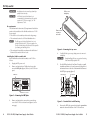
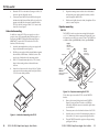
Slide the top plate up the pipe until the pipe collar is
positioned just below the cable access hole. Tighten the
set screws until they just grip the pipe. At least three set
screws must come in contact with the pipe.
8.
Ensure that the front of the top plate is facing toward the
projector screen. This may require turning the pipe with a
wrench. When the top plate is level and correctly oriented,
secure it by fully tightening the set screws.
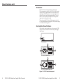
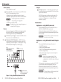
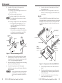
12. Once all cables are routed, insert the lugs on the bottom
plate into the slots on the top plate and slide the bottom
plate into position.
Slots (4)
Lugs (4)
Cable Input from
Ceiling (AV control)
Bottom Plate
Figure 14 — Attaching PMK 450 bottom plate to the
top plate
FRONT
CO
CO
UID
# 093
012
052
LA
WE
PO
R
1
COM
N
TX
TX
M
M
1
2
3
12
P/S PPLY
2
COM
12
RX
RX
-OVE
RED
VD
C 3A
R SU
WE
PO
AD
RLO
X
12V MA
.5A
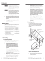
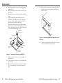
13. Lock the top and bottom plates together with the security
screws and reattach the front and rear plates.
Filler Plate
Cable Access
Hole
REAR
Cable Output
to Projector
Figure 13 — Routing the cables for the PMK 450
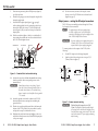
9.
Reroute the cables so that they exit the pipe through the
cable access hole.
10. Connect the cables to the device(s.) Pull excess cable back
into the ceiling.
11. Feed the device(s) output cables to the projector through
the cable access hole and out through the bottom of the
pipe.
14
PS 123 12 VDC, 3 Amp Power Supply • User's Guide
PS 123 12 VDC, 3 Amp Power Supply • User's Guide
15