1
Chapter 2
Installing the 9E423-36 Module
The 9E423-36 module occupies a single slot in the SmartSwitch 9000 chassis.
NOTE
The INB Terminator Modules are purchased separately and must be installed on the rear
of the chassis before powering up this module. Refer to the INB Terminator Modules
Installation Guide for information and installation procedure.
Unpacking the Module
1. Carefully remove the module from the shipping box. (Save the box and
packing materials in the event the module must be reshipped.)
2. Remove the module from the plastic bag. Observe all precautions to prevent
damage from Electrostatic Discharge (ESD).
3. Carefully examine the module, checking for damage. If any damage exists,
DO NOT install the module. Contact Cabletron Systems Technical Support
immediately.
User Accessible Components
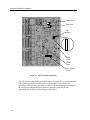
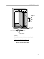
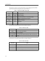
Figure 2-1 shows the various components that can be accessed by users. These
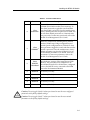
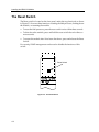
consist of an eight-position dip switch (explained on the next page), replaceable
PROMs, and sockets for memory and flash upgrades. These will be used for
future upgrades. Instructions for installing the components will be supplied with
the upgrade kit.
2-1