1
40GXC / 38GXC Cooling Only
40GXQ / 38GXQ Heat Pump
Inverter---Driven High Wall Duct---Free Split System
Sizes 009 to 012
Service Manual
INTRODUCTION
SAFETY CONSIDERATIONS
This Service Manual provides the necessary information to service,
repair, and maintain the 38/40GXC(Q).
TABLE OF CONTENTS
PAGE
SAFETY CONSIDERATIONS . . . . . . . . . . . . . . . . . . . . . . . . . 1
MODEL / SERIAL NUMBER NOMENCLATURE . . . . . . . . . 2
STANDARD FEATURES AND ACCESSORIES . . . . . . . . . . . 3
SPECIFICATIONS . . . . . . . . . . . . . . . . . . . . . . . . . . . . . . . . . . . 4
DIMENSIONS . . . . . . . . . . . . . . . . . . . . . . . . . . . . . . . . . . . . . . 5
CLEARANCES . . . . . . . . . . . . . . . . . . . . . . . . . . . . . . . . . . . . . 6
SYSTEM OPERATING ENVELOPE . . . . . . . . . . . . . . . . . . . . 7
ELECTRICAL DATA . . . . . . . . . . . . . . . . . . . . . . . . . . . . . . . . 7
WIRING . . . . . . . . . . . . . . . . . . . . . . . . . . . . . . . . . . . . . . . . . . . 7
CONNECTION DIAGRAMS . . . . . . . . . . . . . . . . . . . . . . . . . . 7
WIRING DIAGRAMS . . . . . . . . . . . . . . . . . . . . . . . . . . . . . . 8--9
REFRIGERATION CYCLE DIAGRAM . . . . . . . . . . . . . . . . . 10
REFRIGERANT LINES . . . . . . . . . . . . . . . . . . . . . . . . . . . . . 11
SYSTEM EVACUATION AND CHARGING . . . . . . . . . . . . . 11
CONTROL SYSTEM . . . . . . . . . . . . . . . . . . . . . . . . . . . . 12--13
SEQUENCE OF OPERATION . . . . . . . . . . . . . . . . . . . . . . . . 13
Improper installation, adjustment, alteration, service, maintenance,
or use can cause explosion, fire, electrical shock, or other
conditions which may cause death, personal injury, or property
damage. Consult a qualified installer, service agency, or your
distributor or branch for information or assistance. The qualified
installer or agency must use factory--authorized kits or accessories
when modifying this product. Refer to the individual instructions
packaged with the kits or accessories when installing.
Follow all safety codes. Wear safety glasses, protective clothing,
and work gloves. Use quenching cloth for brazing operations.
Have fire extinguisher available. Read these instructions
thoroughly and follow all warnings or cautions included in
literature and attached to the unit. Consult local building codes and
National Electrical Code (NEC) for special requirements.
Recognize safety information. This is the safety--alert symbol !!
When you see this symbol on the unit and in instructions or
manuals, be alert to the potential for personal injury.
Understand these signal words: DANGER, WARNING, and
CAUTION. These words are used with the safety--alert symbol.
DANGER identifies the most serious hazards which will result in
severe personal injury or death. WARNING signifies hazards
which could result in personal injury or death. CAUTION is used
to identify unsafe practices which may result in minor personal
injury or product and property damage. NOTE is used to highlight
suggestions which will result in enhanced installation, reliability, or
operation.
!
WARNING
MODES OF OPERATION . . . . . . . . . . . . . . . . . . . . . . . . . 13--15
ELECTRICAL SHOCK HAZARD
TROUBLESHOOTING . . . . . . . . . . . . . . . . . . . . . . . . . . . . . . 16
Failure to follow this warning could result in personal injury
or death.
DIAGNOSTIC CHARTS . . . . . . . . . . . . . . . . . . . . . . . . . . . . . 23
APPENDIX . . . . . . . . . . . . . . . . . . . . . . . . . . . . . . . . . . . . 24--27
Before installing, modifying, or servicing system, main
electrical disconnect switch must be in the OFF position.
There may be more than 1 disconnect switch. Lock out and
tag switch with a suitable warning label.
MODEL NUMBER NOMENCLATURE
INDOOR UNIT
40
GXQ
009
1--- 01
---
Voltage
1 --- 115 ---1 ---60
Fan Coil Unit
Nominal Capacity
009 --- 3/4 Ton
012 --- 1 Ton
38/40GXQ
Unit Type
GXQ --- Heat Pump
GXC --- Cooling Only
OUTDOOR UNIT
38
GXQ
009
1--- 01
---
Air ---Cooled Condenser
Voltage
1--- 115 ---1 ---60
Unit Type
GXQ --- Heat Pump
GXC --- Cooling Only
Nominal Capacity
009 --- 3/4 Ton
012 --- 1 Ton
Use of the AHRI Certified
TM Mark indicates a
manufacturer’s
participation in the
program For verification
of certification for individual
products, go to
www.ahridirectory.org.
SERIAL NUMBER NOMENCLATURE
01
06
V
00001
Week of Manufacture
Serial Number
Manufacturing Site
Year of Manufacture
2
STANDARD FEATURES AND ACCESSORIES
S
S
INDOOR UNITS
S
S
S
S
S
S
S
S
S
S
S
S
S
S
S
S
S
S
S
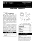
A07892
Fig. 1 – Condensate Pump Accessory
On high wall fan coils, the condensate pump accessory is
recommended when adequate drain line pitch cannot be provided,
or when the condensate must move up to exit.
The pump has a lift capability of 12 ft (3.6 m) on the discharge side
if the pump is mounted in the fan coil or 6 ft (1.8 m) on the suction
side if the pump is remote mounted.
S
S
S
A
F
S
S
O
O
O
O
Legend
S Standard
A Accessory
O Optional
F Field Fabricated
* For Residential applications. For Commercial applications, warranty is 1
year for parts and 5 years for compressor.
3
38/40GXQ
Ease Of Installation
Mounting Brackets
Low Voltage Controls
Comfort Features
Microprocessor Controls
Wireless Remote Control
Rapid Cooling/Heating
Automatic Air Sweep
Cold Blow Prevention
Continuous Fan *
Auto Restart Feature
Memory Function
Auto Changeover
Energy Saving Features
Inverter Driven Compressor
Sleep Mode
24 Hour Stop/Start Timer
Safety And Reliability
Indoor Unit Freeze Protection
3 Minute Compressor Time Delay
High Compressor Discharge Temperature
Low Voltage Protection
Compressor Overload Protection
Compressor Over current Protection
IPM Module Protection
Ease Of Service And Maintenance
Cleanable Filters
Diagnostic LED’s On Outdoor Board
Error Messages Displayed Front Panel
Application Flexibility
Condensate Pump
Wind Baffle
Standard Warranty
6 Year Compressor Limited Warranty*
2 Year Parts Limited Warranty*
Extended Warranty
6 --- 10 Year Compressor Only
2 --- 6 Year Parts Only
2 --- 6 Year Parts; 1--- 6 Yr Labor
2 --- 6 Yr Parts; 6--- 10 Yr Compressor Only; 1--- 6 Yr Labor
Outdoor
Coil
Indoor
Motor
Indoor
Coil
Refrigerant
Lines
38/40GXQ
Outdoor
Motor
Compressor
Refrigerant
System
PRODUCT SPECIFICATIONS
System Model Number
System Voltage
Control Voltage
Capacity (Btuh) Clg/Htg
SEER/HSPF
53GXC009--- --- --- 1
115 V
0 --- 24v DC
8,600/ --16/ ---
53GXC012--- --- --- 1
115 V
0 --- 24v DC
12,000/ --16/ ---
560
560
Refrigerant Type
Design Pressure (PSIG)
Type
Model
Oil Charge (POE ---oz)
Rated Current (RLA)
Locked Rotor Amp (LRA)
Rpm/CFM
53GXQ012--- --- --- 1
115 V
0 --- 24v DC
12,000/11,200
16/7.7
R---410A
Metering Device
Charge (lb)
53GXQ009--- --- --- 1
115 V
0 --- 24v DC
8,600/10,800
16/7.7
560
560
Capillary Tube at Outdoor
2.65
C ---6RZ092H1AB
11.6
4
33
830/1060
2.8
2.65
Twin Rotary Inverter Driven
C ---6RZ092H1AB
C ---6RZ092H1AB
11.6
11.6
3.92
4
33
33
830/1060
830/1060
2.8
C ---6RZ092H1AB
11.6
3.92
33
830/1060
15.7 … 3
15.7 … 3
15.7 … 3
Motor (hp)
0.04
0.04
0.04
0.04
Capacitor
2.5µF/450VAC
2.5µF/450VAC
2.5µF/450VAC
2.5µF/450VAC
Diameter (in) .. No. of Blades
Face Area (sq. ft)
15.7 … 3
3.5
No. Rows
2
Fins per inch
18
Circuits
Motor Watts/HP
Rpm/Cfm (High)
Rpm/Cfm (Medium)
Rpm/Cfm (Low)
2
20/0.027
1200/290
1060/245
700/224
1350/315
1200/268
1100/245
1200/290
1060/245
700/224
1350/315
1200/268
1100/245
Blower Diameter … Length (in)
Face Area (sq. ft)
3.8 … 23
2.4
3.6 … 24.3
2.4
3.8 … 23
2.4
3.6 … 24.3
2.4
2
3
65
35
35
100
50
50
No. Rows
2
Fins per inch
18
Circuits
Connection Type
Liquid (Mix Phase) (in) OD
Vapor Line (in) OD
Condensate Drain (in)
Maximum Length (ft)
Max Lift (Fan Coil Above) (ft)
Max Drop (Fan Coil Below) (ft)
2
3
Flare
1/4”
1/2”
ID = 1/2” OD=5/8”
65
35
35
65
35
35
4
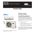
DIMENSIONS -- INDOOR
H
D
W
A08289
Unit Size
9k
12k
W
In. (mm)
30.3 (770)
32.7 (830)
H
In. (mm)
9.8 (250)
11.2 (285)
D
In. (mm)
7.84 (1.99)
8.9 (225)
Net Operating Weight
Lbs. (Kg)
18.7 (8.5)
24.2 (11)
38/40GXQ
Fig. 2 – Dimensions of Indoor Unit
DIMENSIONS - OUTDOOR
W
D
H
A08290
Unit Size
9k & 12k
W
In. (mm)
33.4 (848)
D
In. (mm)
12.6 (320)
Fig. 3 – Dimensions of Outdoor Unit
5
H
In. (mm)
21.3 (540)
Net Operating Weight
Lbs. (Kg)
88 (40)
CLEARANCES -- INDOOR
CEILING
6" (0.15m) min.
5"
(0.13m)
min.
5"
(0.13m)
min.
6' (1.8m)
38/40GXQ
FLOOR
A07891
Fig. 4 – Indoor unit clearance
CLEARANCES - OUTDOOR
A
Air-inlet
E
D
B
C
Air-outlet
A07894
UNIT
A
B
C
D
E
12k in. (mm)
20 (508)
20 (508)
24 (610)
12 (305)
12 (305)
Fig. 5 – Outdoor Unit Clearance
6
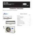
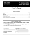
38/40GXQ SYSTEM OPERATING ENVELOPE
Outdoor Temperature (_C)
--- 40 --- 35 --- 30 --- 25 --- 20 --- 15 --- 10 --- 5 0
5 10 15 20 25
120
30
35
40
45
50
55
60
60
55
50
45
100
95_F
40
90
Heating
Continuous
Operation
70
35
Cooling
Continuous
Operation
80_F
30
25
20
60
55_F
14_F
50
40
--- 10
15
60_F
0
10
20
30
40
75_F
55_F
10
115_F
38/40GXQ
80
Indoor Temperature (_C)
Indoor Temperature (_F)
110
5
50
60
70
80
90
Outdoor Temperature (_F)
100
110
120
130
0
140
NOTE: Low ambient controls cannot be used with these systems
A09247
Fig. 6 – 38/40GXQ System Operating Envelope
ELECTRICAL DATA
UNIT
SIZE
009
012
SYSTEM
VOLTAGE
OPERATING
VOLTAGE*
VOLTS--- PH--- HZ
MAX/MIN
115 ---1 ---60
COMPRESSOR
127/104
RLA
LRA
4.0
33
4.0
33
OUTDOOR FAN
FLA
.6
HP
W
.04
INDOOR FAN{
VOLTS
30
115
MCA
MAX
FUSE/CB
AMP
FLA
HP
W
.3
.027
30
20
25
.45
.027
20
20
25
* Permissible limits of the voltage range at which the unit will operate satisfactorily
{ Indoor fan powered from outdoor unit.
LEGEND
FLA --- Full Load Amps
LRA --- Locked Rotor Amps
MCA --- Minimum Circuit Amps
RLA --- Rated Load Amps
WIRING
The main power is supplied to the outdoor unit. The field supplied connecting cable from the outdoor unit to indoor unit consists of four
wires and provides the power for the indoor unit as well as the communication signal between the outdoor unit and indoor unit.
Voltage drop on the connecting cable should be kept to a minimum. Use cable size and max length below:
18 AWG
16 AWG
50 ft. (16 m)
100 ft. (33 m)
CONNECTION DIAGRAMS
CONNECTING CABLE
L
N
L
N
GND
Main Power Power to
Indoor Ground
Supply
Unit
115-1-60
L
S
Control
115-1-60
9 &12K Outdoor Unit
N
Power to
Indoor
Unit
GND
S
Ground
Control
115-1-60
Use a four (4) Wire Cable
(Do Not use thermostat wire)
9 &12K Indoor Unit
A08292
Fig. 7 – Connection Diagrams
7
8
X2
TRANSFORMER
X1
X9 X12
FAN1
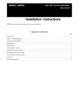
COOLING ONLY INDOOR UNIT
115-1-60
N
ACL1
DATA1
I.D. FAN
MOTOR
DISPLAY BOARD
38GXC009/012---1
LOUVER MOTOR
X3
X13
X9 MK1
AP2
RETURN
AIR TEMP.
SENSOR
ID COIL
TEMP.
SENSOR
WIRING DIAGRAMS
BRN
BLU
YE/GN
BLK
L
N
XT
S
{
FIELD
POWER
SUPPLY
N
N
BRN
BLU
BRN
3
BLK
WHT
WHT
YE/GN
E
2 4
1
FILTER
X1 (COM)
X2 (N)
X3 (L)
X5
E (X4)
CN3
BLK
X7
BRN
O.D. FAN
MOTOR
RED
X21 X14
NO
RELAY
COM
BRN
CN2
CAP
BLU
X15
WHT
1
2
GRN
CN7
40GXC009/012---1
YE/GN
BLU
X10
MAIN
CN4
RED
CURRENT
SENSOR
1
2
CAP
BRN
X6
CN8
COOLING ONLY INDOOR UNIT
115-1-60
E
X16
CN1
COMP.
DISCHARGE
TEMP.
SENSOR
Fig. 8 – 38--40GXC009/012 Cooling Only Wiring Diagram
YE/GN
BLU
XT2
S
N
L
L
L
YE/GN
OD COIL
TEMP.
SENSOR
OD AIR
TEMP.
SENSOR
38/40GXC(Q)
X9
CN6
BRN
FILTER
BRN
BLU
WHT
AC
AC
BLU
C
X17
A09344
E YE/GN
W(13)
RED
GRN
V(X12)
RED
S
COMP
GRN
U(X11)
WHT
R
9
TC
X2
X9 X12
I.D. FAN
MOTOR
FAN1
N
ACL1
DATA1
38GXQ009/012---1
TRANSFORMER
X1
AP2
X13
RETURN
DISPLAY BOARD
AIR TEMP.
SENSOR
HEATPUMP INDOOR UNIT
115-1-60
LOUVER MOTOR
X3
X9 MK1
ID COIL
TEMP.
SENSOR
BLK
BRN
BLU
YE/GN
L
N
S
XT
WIRING DIAGRAMS (CONT.)
N
N
10BK
2
4
WHT
RED
YE/GN
E
1 3
FILTER
RELAY
CN3
X18
COM NO
4 WAY VALVE
X1 (COM) X8
X2 (N)
X3 (L)
X5
X4 (E)
BRN
WHT
1
2
GRN
2
1
CAP
BRN
X6
CN8
X9
CN6
BRN
FILTER
BRN
R
AC
S
RED
RED
C
E
AC
BLU
X17
V(X12) W(X13)
GRN
GRN
U(X11)
BLU
40GXQ009/012---1
CAP
BLU
X15
CN4
CN7
WHT
WHT
HEATPUMP OUTDOOR UNIT
115-1-60
YE/GN
38/40GXC(Q)
E
BLU
X10
MAIN
CN1
RED
COMP.
DISCHARGE CURRENT
TEMP.
SENSOR
SENSOR
X7 X16
O.D. FAN
MOTOR
RED
X21 X14
BLK
BRN
CN2
OD AIR
TEMP.
SENSOR
Fig. 9 – 38--40GXQ009/012 Heat Pump Wiring Diagram
YE/GN
BLU
BRN
BRN BLU
XT2
S
N
L
L
L
{
FIELD
POWER
SUPPLY
YE/GN
OD COIL
TEMP.
SENSOR
A09345
YE/GN
10
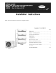
FLARE CONNECTION
HEAT
EXCHANGER
(EVAPORATOR)
FLARE CONNECTION
INDOOR UNIT
SERVICE VALVE
SUCTION
ACCUMULATOR
COMPRESSOR
SUCTION
DISCHARGE
CAPILLARY TUBE
Fig. 10 – Refrigeration Cycle Diagram
FIELD
PIPING
CHECK VALVE
COOLING
HEATING
(HEAT PUMP ONLY)
REVERSING
VALVE
HEAT
EXCHANGER
(CONDENSER)
LIQUID
TWO PHASE
OUTDOOR UNIT
(HEATING MODEL ONLY)
LIQUID HTQ
SERVICE VALVE
W/ GUAGE PORT
REFRIGERATION CYCLE DIAGRAM
38/40GXC(Q)
A09248
REFRIGERANT LINES
Routing – Refrigerant lines can be routed in any of the four
directions shown in Fig. 10.
SYSTEM EVACUATION AND
CHARGING
As viewed from front
!
CAUTION
UNIT DAMAGE HAZARD
3 Left Exit
1 Right Exit
2 Right Rear Exit
Never use the system compressor as a vacuum pump.
(b)
Fig. 11 – Refrigerant Line Routing
A08281
General Guidelines:
1. The 38GXQ units are shipped with full charge of R--410A
refrigerant. All charges, line sizing, and capacities are based
on runs of 25ft (7.6 m). For runs over 25ft (7.6 m), consult
long line section for charge adjustments.
2. Refrigerant lines should not be buried in the ground. If it is
necessary to bury the lines, not more than 36 inches (914
mm) should be buried. Provide a minimum of 6 inch (152
mm) vertical rise to service valves to prevent refrigerant
migration.
3. Both lines must be insulated. Use a minimum of 1/2 inch
(12.7 mm) thick insulation. Closed--cell insulation is
recommended in all long--line applications.
4. Special consideration should be given to isolating
interconnecting tubing from the building structure. Isolate
the tubing so that vibration or noise is not transmitted into
the structure.
Long Line Applications:
1. A field fabricated wind baffle is recommended.
2. No change in line sizing is required.
3. Add refrigerant per table below.
ADDITIONAL CHARGE TABLE
9K hp
12K hp
Refrigerant tubes and indoor coil should be evacuated using the
recommended deep vacuum method of 500 microns. The alternate
triple evacuation method may be used if the procedure outlined
below is followed. Always break a vacuum with dry nitrogen.
SYSTEM VACUUM AND CHARGE
Using Vacuum Pump
1. Completely tighten flare nuts A, B, C, D, connect manifold
gage charge hose to a charge port of the low side service
valve. (See Fig. 15.)
2. Connect charge hose to vacuum pump.
3. Fully open the low side of manifold gage. (See Fig. 16)
4. Start vacuum pump
5. Evacuate using either deep vacuum or triple evacuation
method.
6. After evacuation is complete, fully close the low side of
manifold gage and stop operation of vacuum pump.
7. The factory charge contained in the outdoor unit is good for
up to 25 ft. (8 m) of line length. For refrigerant lines longer
than 25 ft (8 m), add 0.1 oz. per foot of extra piping up to
the maximum allowable length.
8. Disconnect charge hose from charge connection of the low
side service valve.
9. Fully open service valves B and A.
10. Securely tighten caps of service valves.
Additional Charge, oz./ft
ft (m)
10 --- 25
(3.05 --- 7.62)
>25 --- 65
(7.62--- 19.81)
None
0.48
9 & 12 KBTU/H models
Heating:
9 & 12 KBTU/H models
7%
Low Side
B
High Side
C
D
A07360
Fig. 12 – Service Valve
Capacity, % Loss
Line Length, ft (m)
25
45
65
(7.62)
(13.7)
(19.8)
0%
2%
5%
0%
A
Service Valve
4. Reduction in capacity due to long lines can be calculated
from the chart below.
CAPACITY LOSS
Cooling:
Indoor Unit
Refrigerant
Outdoor Unit
Manifold Gage
500 microns
Low side valve
11%
High side valve
Charge hose
Charge hose
Vacuum pump
Low side valve
A07361
Fig. 13 – Manifold
11
38/40GXC(Q)
(a)
Unit Size
Failure to follow this caution may result in equipment
damage or improper operation.
4 Left Rear Exi
SYSTEM SAFETIES
Safety
3 Minute Time Delay
Freeze Protection, Indoor Coil
High Compressor Discharge Temperature
Low Voltage Protection
High Condensing Temperature
Compressor Over Current Protection
IPM Module Protection
CODE
--E2
E4
E5
H3
H4
H5
POSSIBLE CAUSE
--Low Refrigerant Charge, Blocked Indoor Air Flow, or Dirty Air Filter
Low Refrigerant Charge, or Blocked Capillary
Low Voltage
High Ambient Temperature, or Loss of Condenser Airflow
High Ambient Temperature, or Loss of Condenser Airflow
Loss of Cooling to Heat Sink, High Ambient, Low Voltage, or Bad Connections
CONTROL SYSTEM
38/40GXC(Q)
The 53GXC(Q) units are equipped with microprocessors in the
indoor and outdoor units. They perform the following two
functions:
1. Provide safety for the system
2. Control the system and provide optimum levels of comfort
and efficiency.
Stop Compressor
Reduce Comp. Freq.
No Freq. Increase
3 Minute Time Delay
In order to protect the compressor, there is a 3 minute delay on
break even if the control is calling for heating or cooling.
Indoor Coil Freeze Protection
217.4
230
°F
A09347
Fig. 15 – Compressor Gas Discharge Temperature Protection
When the unit is running in the COOL or DRY MODE, the indoor
coil can freeze due to any of the following:
S
S
S
S
S
208.4
When the compressor discharge temperature drops below 194 F,
the unit will resume normal operations.
Low system charge
Low Voltage Protection
Reduced indoor airflow
If the incoming voltage is below the minimum allowed, E5 will be
displayed on the front panel of the indoor unit.
Restricted refrigerant flow
Condenser High Temperature Protection
Low ambient temperature (outdoor)
Low load (indoor)
The indoor coil thermistor monitors the coil temperature
continuously. Any time the coil temperature drops below 30.2_F
(--1_C), the compressor and the outdoor fan (30 seconds later) will
be switched off until the coil temperature rises above 42.8_F (6_C)
and the compressor was off for a minimum of 3 minutes.
Compressor
≥3 min
30 S
Outdoor Fan
Condenser high temperature can occur due to any of the following
conditions:
S
S
S
High outdoor ambient
Outdoor fan blocked
Outdoor coil blocked
The outdoor coil thermistor continuously monitors the temperature
and communicates with the microprocessor. Depending on the
temperature measured, the compressor will be allowed to increase
the frequency if needed to meet the load or is forced to run at the
current or reduced frequency. If the temperature gets excessively
high the compressor will be de--energized as shown below:
Indoor Fan
30.2 ° F
42.8° F
A09346
Fig. 14 – Coil Freeze Protection
High Compressor Discharge Temperature
The compressor discharge temperature can be high due to any of
the following:
S
S
Stop Compressor
Reduce Comp. Freq.
No Freq. Increase
Low refrigerant charge
Blocked capillary
The compressor discharge line thermistor continuously monitors
the temperature and communicates with the microprocessor.
Depending on the temperature measured, the compressor will be
allowed to increase the frequency to meet the load or is forced to
run the current or reduced frequency. If the temperature gets
excessively high, the compressor will be de--energized as shown
below:
133
136.4
143.6
°F
A09348
Fig. 16 – High Temperature Protection
When the outdoor coil temperature drops to 123.8 F, the unit will
resume normal operations.
NOTE: In heating the indoor fan is de--energized 60 seconds after
the compressor is de--energized.
12
MODES OF OPERATION
Compressor Over Current Protection
Over current protection can result due to any of the following:
S
S
S
The ambient temperature is too high
Locked rotor on the compressor
Blockage in the refrigeration circuit (capillary tubes for
example)
Outdoor air is blocked or restricted
The compressor current is monitored continuously. Based on the
amp draw measured, the microprocessor will allow the compressor
to increase frequency, maintain frequency, drop frequency, and
eventually de--energized the compressor if excessive amps are
experienced.
S
The units have five main operating modes:
1. Fan only
2. Cooling
3. Heating (heat pump only)
4. Auto
5. Dry (Dehumidification)
The units also have the manual mode that allows the unit to be
operated without the remote control.
Fan Only Mode
In this mode, the system circulates the room air without changing
the room air temperature.
II
Compressor
9K
12K
6
7
IM
7
8
ID
8
9
IO
9
10
Outdoor Fan
Indoor Fan
II
IM
ID
IO
A09349
Fig. 17 – Overcurrent Protection
IPM Module Protection
This can be caused by any of the following:
S
S
S
S
In this mode, the system cools and dries the room air with the fan
running continuously, either at a selected fan speed or Auto fan
speed. The fan runs even when the compressor cycles off. This
feature enhances room comfort and efficiency of the system.
Compressor, Outdoor Fan Operations, and Indoor fan
Operation
As shown below, the compressor and outdoor fan motor cycle on
and off based on the conditions of the set point and the room
temperature. The indoor fan runs continuously.
Loss of cooling to the heat sink
Tamb ≤ TS- 3.6°F
High ambient temperatures
TS+ 1.8°F
TS
Low voltage
Loose screws fastening the board to the heat sink
When this occurs, H5 is displayed on the LED display on the front
panel of the indoor unit.
A wireless remote control, supplied with the unit, is the interface
between the fan coil and the user. The wireless remote control has
the following characteristics:
S
Dedicated controllers for _C or _F. Each indoor units
comes with two remotes that are clearly labeled for the
appropriate temperature scale.
S
The remote control range is from 61_F (16.1_C)to 86_F
(30_C).
S
The same remote is used for both cooling only and heat
pump units
S
S
The wireless remote control range is 25 ft (7.6 m).
S
Compressor
matches load
TS- 3.6°F
Compressor
30S
≥ 3 min
30S
Outdoor Fan
SEQUENCE OF OPERATION
Interface
Tamb ≥TS+1.8 °F
Indoor Fan
A09249
Fig. 18 – Cooling Mode
Indoor Fan Operation -- Cooling
When in cooling mode, the fan runs continuously either at the
chosen set speed, or in Auto mode, where the speed is determined
by the microprocessor based on the difference between the room
temperature and the temperature set point as shown below:
High
Medium
Low
The same remote can be used to control more than one
unit.
TS
If the remote control is lost, damaged, or the batteries are
exhausted, the system can be operated using the manual
button located under the front panel
TS + 3.6°F
A09250
Fig. 19 – Auto Fan -- Cool Only Mode
13
38/40GXC(Q)
Cooling Mode
Current
Frequency
Heating Mode
In this mode, the system heats the room air with the indoor fan
running at either the selected speed or on Auto. As the cooling
mode, the indoor fan will run continuously unless interrupted by
the cold blow algorithm. This algorithm will not allow the fan to
run if the indoor coil temperature drops below a preset value.
Compressor and fan operation
As shown below, the compressor and outdoor fan cycle on and off
based on the actual room temperature versus the set point. The
outdoor fan is de--energized 30 seconds after the compressor is
de--energized. The reversing valve is energized in heating and will
stay energized for 2 minutes after the compressor is de--energized.
The reversing valve is energized 2 seconds before the compressor
is energized.
If the indoor coil temperature is ≥106_F (41.1_C) and
the room temperature is ≥75_F (23.4_C, the indoor fan
will run at low speed for 1 minute.
After one of the above steps occur, the indoor fan speed will be
determined as shown below:
S
TS+ 3.6°F
TS+ 9°F
High
Compressor
matches load
Medium
TS+ 3.6°F
Compressor
Low
≥ 3 minutes
Reversing Valve
2 minutes
Outdoor Fan
2S
100.4 °F
109.4 °F
30 S
Cold Blow
prevention
Indoor Fan
A09252
Fig. 20 – Heat Mode
Indoor Fan Operation – Heating
When in heating mode, as long as the coil temperature is above the
threshold for cold blow prevention, the fan runs continuously
either at the chosen set speed, or in Auto mode, where the speed is
determined by the microprocessor based on the difference between
the room temperature and the temperature set point as shown
below:
A09354
Fig. 22 – Cold Blow Prevention
Defrost
Defrost is controlled by the microprocessor and will occur if the
unit operated in the heating mode for at least 45 minutes and any of
the conditions below lasted for more than 3 minutes.
28.4
Coil Temperature
38/40GXC(Q)
If the indoor coil temperature is < 106_F (41.1_C) and
the room temperature is < 75_F (23.4_C), there will be a
3 minute time delay before the indoor fan runs at low
speed for 5
minutes.
S
User selected
TS+ 9°F
Cold Blow Prevention
This function prevents the cold air from blowing into a space when
in heat mode. When there is a demand for heating one of the
following conditions occurs:
21.2
14
High
10.4
Medium
Low
23
TS + 1.8°F
TS + 5.4°F
32
41
A09254
Fig. 21 – Auto Fan -- Heat Mode
°F
Outdoor Temperature
A09355
Fig. 23 – Defrost
The defrost cycle will terminate 12 minutes after the initiation of
the defrost cycle or when the coil temperature is ≥50_F (10_C).
The defrost algorithm is shown below:
Defrost Initiated
Compressor
Reversing Valve
Outdoor Fan
Defrost Terminated
25 Hz
12 min or tube
temp ≥ 50°F
75 S
Cold Blow
Prevention
Indoor Fan
A09256
Fig. 24 – Defrost (continued)
14
AUTO MODE
SLEEP MODE
When the Auto setting is selected, at startup the unit will run in
cooling, fan only, or heating based on the room temperature at
shown below.
Additional energy savings can be realized by selecting the Sleep
mode. When the sleep setting is selected, the temperature set point
is adjusted automatically as shown below:
At Startup
TS+3.6°F
°F
TS+1.8°F
77
73.4
Fan
TS
Heating
TS-1.8°F
68
64.4
Cooling
Heating
TS-3.6°F
1 HR
A09357
Fig. 25 – AUTO Mode
After startup and if the unit is running in cooling, the compressor
will be de--energized when the room temperature is 73.4_F (23_C).
If the unit was running in heating, the compressor will be
de--energized when the room temperature is 73.4_F (23_C).
There is a 6 minute time delay before modes are switched.
2 HR
A09258
Fig. 26 – SLEEP Mode
15
38/40GXC(Q)
Room Temperature
Cooling
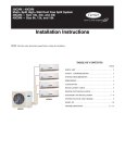
TROUBLESHOOTING
This section provides the required flow charts to troubleshoot problems that may arise.
NOTE: Information required in the diagnoses can be found either on the wiring diagrams or in the appendix.
Required Tools:
The following tools are needed when diagnosing the units:
S Digital multimeter
S Screw drivers (Phillips and straight head)
S Needle--nose pliers
38/40GXC(Q)
Recommended Steps
1. Refer to the diagnostic hierarchy chart below and determine
the problem at hand.
2. Go to the chart listed in the diagnostic hierarchy and follow
the steps in the chart for the selected problem.
Error codes, if they occur, are displayed on the LED panel on the front cover of the unit. In addition, some of the same errors are displayed
by flashing LEDs on the outdoor board. If possible, always check the diaganostic codes displayed on the indoor unit first.
For problems requiring measurements at the control boards:
1. Always disconnect the main power.
2. When possible check the outdoor board first.
3. Start by removing the outdoor unit top cover.
4. Reconnect the main power
5. Probe the outdoor board inputs and outputs with a digital
multi--meter referring to the wiring diagrams and
input/output charts found in the appendix.
6. Connect the red probe to hot signal and the black probe to
the ground or negative.
7. Note that some of the DC voltage signals are pulse will give
continuously variable readings.
8. If it is necessary to check the indoor unit board you must
start by disconnecting the main power.
9. Next remove the front cover of the unit and then control
box cover.
10. Carefully remove the indoor board from the control box,
place it face up on a plastic surface (not metal).
11. Reconnect the main power and repeat steps 5,6, and 7.
12. Disconnect main power before reinstalling board to avoid
shock hazard and board damage.
For problems requiring pressure measurements:
1. Connect the low pressure gauge to the gauge connection
port on the suction service valve
2. Set compressor speed using the system remote control as
follows:
COOLING – Select a set point of 66_F and push the sleep
button 4 times
HEATING – Select a set point of 84_F and push the sleep
button 4 times
3. With the system operating at steady state conditions, make
the following measurements:
a. Outdoor ambient temperature
b. Compressor discharge temperature as close to the
compressor as possible
c. Suction pressure
4. Refer to the Appendix and select a suction pressure and
discharge temperature range based on the outdoor ambient
temperature for either cooling or heating. Compare the
measured pressure and temperature to the values in the chart
to determine if the operating pressures and temperatures of
the systems are normal or not.
Unit has a problem
Unit displays a
diagnostic code
Refer to page ---, identify
error code and use
appropriate diagnostic chart
Unit not running and
no diagnostic code
Unit running but not
optimally
Go to chart # 8
Go to chart # 9 &10
A09359
Fig. 27 – Diagnostic Hierarchy
16
DIAGNOSTIC CHARTS
No
Indoor fan motor
running?
Check motor
Chart
Yes
Connect low side gauge at
suction service valve.
Measure discharge temp.*
No
Check for leaks.
Yes
Problem solved
Yes
Reclaim charge and fix
leak.
Clean indoor coil and
filter. Problem fixed?
Replace indoor board.
Yes
Check indoor coil
temperature thermistor .
Chart 4, ok?
38/40GXC(Q)
No
Weigh in charge.
No
Replace thermistor
A09360
Fig. 28 – Indoor Freeze Protection
Connect low side gauge at
suction service valve.
Measure discharge temp.*
Ok
Check compressor
discharge line thermistor .
Ok?
No
High head, low suction?
Yes
Check for leaks.
Replace thermistor
Yes
No
Suction and discharge
pressures low?
No
Yes
Yes
Restriction in refrigeration
circuit.
Yes
Reclaim charge and fix
leak.
Check for blocked
capillary tube or a restriction
in liquid line
Weigh in charge.
A09361
Fig. 29 – High Compressor Discharge Temperature
17
DIAGNOSTIC CHARTS (CONT.)
Reset circuit breaker. Is
problem fixed?
Yes
Problem fixed
Notes:
Before measuring the Volts DC on outdoor TB,
disconnect the field wire on terminal S.
No
Check the wires (type) and
connections between
Indoor and outdoor units *
No
Fix connection or
replace wiring
Before measuring the Volts DC on Indoor TB,
disconnect the field wire on terminal S.
Yes
Reset main power and
restart system using remote.
Problem persists?
No
Have the red probe of the meter on terminal S
and the black probe on terminal N. Reconnect
wiring when measurements are complete.
No further action is
required
38/40GXC(Q)
Yes
Measure Volts DC on
outdoor TB between S & N.
Ok? **
Yes
Measure Volts DC on
indoor TB between S & N.
Ok? **
No
Replace outdoor board.
Recheck wiring and
connections
Yes
No
Replace indoor board.
*
Thermostat wires cannot be used. Wires should be connected per connection diagrams. Failure to do that will result in a
communication error. Polarity needs to be maintained between indoor and outdoor units
** There is 3 minutes to make the measurement before the diagnostic light comes back on.
A09362
Fig. 30 – Communication Error
Reset main power and
restart system using remote.
Problem persists?
No
No further action is
required
Yes
Check sensor connector
at ID or OD board
Connection good?
No
Fix connection
Yes
Check input and output
on indoor or outdoor board.
No
Replace board
Yes
Check sensor resistance.
Appendix A4
No
Replace sensor
Yes
Double check connection,
for corrosion or high
resistance.
A09363
Fig. 31 – Temperature Sensor
18
DIAGNOSTIC CHARTS (CONT.)
Yes
Is unit running in outdoor
ambient higher than
110 °F?
Beyond operating range
No
No
Outdoor coil clean?
No
Clean coil.
Problem persists?
Yes
Problem solved
Yes
Check outdoor coil
temperature thermistor .
Chart 4, ok?
No
No
Replace thermistor .
Problem persists
Problem solved
Check motor for open
or short. Ok?
Yes
38/40GXC(Q)
Yes
Yes
Replace outdoor motor
No
Check output on outdoor
board. Ok?
No
Replace outdoor board
A09364
Fig. 32 – High Condensing Temperature
Is unit running in outdoor
ambient higher than
110 °F?
Yes
Beyond operating range
No
No
Clean coil.
Problem persists?
Outdoor coil clean?
Yes
Check connections from
OD board. Loose, corroded,
or high resistance?
Replace motor
Outdoor motor ok?
Yes
Check output on
outdoor board. Ok?
Yes
Connect low side gauge at
suction service valve.
Measure discharge temp.*
Yes
Clean/repair connection
Problem persists?
No
Check amp draw to
compressor? Values within
range?
No
Problem solved
Yes
No
Replace outdoor board
No
No
High head, high suction?
Yes
Yes
Replace compressor
Problem solved
Yes
No
No
No
Unit is overcharged.
Reclaim charge and weigh
in correct charge.
High head, low suction?
Yes
Restriction in refrigeration
circuit.
Yes
Replace outdoor board
*Measure discharge temperature at the sensor on the discharge
tube. See Appendix A5
A09365
Fig. 33 – Compressor Overcurrent Protection
19
DIAGNOSTIC CHARTS (CONT.)
Check heat sink for
obstruction and dirt
Yes
Clean.
Problem fixed?
Yes
See note below *
Is problem fixed?
No
Check if connection
is loose
No
No
Check voltage and current.
No
38/40GXC(Q)
Ok? See note below **
Measure voltage between
X15 and X9. Ok?
No
Yes
Replace compressor
Check voltage and balance
between any two phases of
U,V, and W. Ok?
No
Replace capacitor.
Problem fixed?
No
Replace outdoor board
* Remove screws, remove heat sink, remove thermal grease. Apply new thermal grease and reassemble.
** Check if voltage between power module P and N is too low and if current is too high. In normal conditions,
voltage between P and N should be about 370V.
A09366
Fig. 34 – IPM Module Protection
No
Try to start unit using auto
Function. Unit runs?
Yes
Use auto function to
shut off unit.
Start unit using remote
control. Audible noise heard?
Unit started?
No
Check batteries. OK?
Yes
Yes
Problem solved
Go to chart 13
No
Check wiring and circuit
breaker and fix
Check input and output on No
outdoor board. Ok?
Replace outdoor board
Is there power to outdoor
unit?
Replace battery
Yes
Problem solved
Reset circuit breaker. Is unit No
running?
No
Yes
Replace indoor board
Yes
Check components. Ok?
Flow charts 10 thru 12
No
Yes
Check fuse on indoor
board. Ok?*
No
No
Replace defective
component
Replace fuse
Yes
Check input and output on
indoor board. Ok?
Yes
Determine defective
component and replace
A09367
Fig. 35 – Unit Not Running, No Diagnostic Code
20
DIAGNOSTIC CHARTS (CONT.)
No
Outdoor coil clean?
No
Clean coil. Problem
persists?
Yes
Problem solved
Yes
No
Indoor filter clean?
No
Clean filter. Problem
persists?
Yes
Problem solved
Yes
No
Check indoor fan
motor
Replace indoor fan
motor.
Connect low side gauge
at suction service valve. Yes
Measure discharge temp.*
38/40GXC(Q)
Yes
Check application
limits.
No
No
Normal suction,
high head?
No
High head, high
suction?
Yes
High head, low
suction?
Yes
Non condensables
in sys. Pump down
and recharge unit
Yes
Unit is overcharged.
Reclaim charge and
weigh in correct charge
See note below *
* Restriction in system. Check capillary tube and check for damage to liquid line between indoor and
outdoor units.
A09368
Fig. 36 – Unit Not Running Optimally
Visually check outdoor
Unit for ice blockage. **
No
Check reversing valve.
Go to flow chart 12
Yes
Check defrost sensor. Ok?
Go to flow chart 2
No
Replace sensor
Yes
Check application limits.
Ok?
No
Beyond operating range
Yes
Check ambient conditions.
Prime icing?
Yes
Explain to customer
* To supplement flow chart 9
** Check for blockage on outdoor coil and drain pan. Are the holes in drain pans blocked?
A09369
Fig. 37 – Unit Not Running Optimally (HP in Heating*)
21
DIAGNOSTIC CHARTS (CONT.)
Visually confirm that fan
blades and outdoor coil
are not blocked.
No
Clear blockage
Yes
Trace connections from
OD board. Connections
ok?
No
Fix connection
Yes
No
38/40GXC(Q)
Check motor windings.
Ok?
Replace Motor
Yes
Motor ok.
A09370
Fig. 38 – Motors
Check RV connection on
outdoor board. Ok?
No
Clean or repair the
connection
Yes
Check RV output on outdoor
board. Ok?
No
Replace outdoor board
Yes
No
Check RV solenoid. Ok?
Replace solenoid
Yes
Replace reversing valve.
A09371
Fig. 39 – Reversing Valve
22
DIAGNOSTIC CHARTS (CONT.)
Check wiring and
connection between
receiver and ID board. Ok?
No
Fix wiring or
connection
Yes
Check input and output
on ID and receiver
boards. Ok?
No
Replace receiver board
Yes
A09372
Fig. 40 – Receiver Board
23
38/40GXC(Q)
Replace remote control
APPENDIX
APPENDIX TABLE OF CONTENTS
DESCRIPTION
NUMBER
Control Board Input or Output Values . . . . . . . . . . . . . . . . . . . . . . . . . . . . . . . . . . . . . . . . . . . . . . . . . . . . . . . . . . . . . . . . . . . . . A1
Diagnostic Codes . . . . . . . . . . . . . . . . . . . . . . . . . . . . . . . . . . . . . . . . . . . . . . . . . . . . . . . . . . . . . . . . . . . . . . . . . . . . . . . . . . . . . A2
Characteristics of Temperature Sensors . . . . . . . . . . . . . . . . . . . . . . . . . . . . . . . . . . . . . . . . . . . . . . . . . . . . . . . . . . . . . . . . . . . . . A3
38/40GXC(Q)
Pressure –Temperature Chart . . . . . . . . . . . . . . . . . . . . . . . . . . . . . . . . . . . . . . . . . . . . . . . . . . . . . . . . . . . . . . . . . . . . . . . . . . . . A4
24
A1 -- CONTROL BOARDS INPUT OR OUTPUT VALUES
INDOOR BOARD
OUTPUT
FAN1:
INPUT
OUTPUT
X2:
X1:
OUTPUT
X3:
OUTPUT
OUTPUT
INPUT
INPUT
X9:
X12:
X9 MK1:
X13:
VOLTAGE
BLACK(24v max) relative to N DC
BLUE (neutral)
BROWN(115v) relative to N AC
[Pin1 BLACK (0--- 115v) Pin2:GREEN(0--- 115v) Pin3:YELLOW(0--- 115v) Pin5:BROWN(0--- 115v)
Pin6:RED(0--- 115v)] relative to Pin4:WHITE
[PIN1:BULE 115v AC relative to PIN2: YELLOW
[Pin1 YELLOW(13±2v AC) relative to Pin2:YELLOW][ Pin3:WHITE(8±2v AC) relative to Pin4:WHITE]
[Pin1 BLUE(0--- 12v) Pin2:PINK(0--- 12v) Pin3:YELLOW(0--- 12v) Pin4:ORANGE(0--- 12v) Pin5:RED(12v)] relative to
heat sink (X101) DC
Multiple Pins (6 PATH) Any Pin (0--- 12v DC ) relative to heat sink (X101)
Multiple Pins (7 PATH)(0--- 12v DC) relative to heat sink (X101)
PIN1:BLACK (0--- 5V DC) relative to PIN2:YELLOW
PIN1:BLACK (0--- 5V DC) relative to PIN2:YELLOW
OUTDOOR BOARD
CONNECTOR
INPUT
X1
INPUT
X2
INPUT
X3
OUTPUT
X5
OUTPUT
X4
INPUT
CN3
INPUT
CN2
INPUT
CN1
OUTPUT
X8
OUTPUT
X18
INPUT
CN4
INPUT
CN7
OUTPUT
CN8
OUTPUT
CN6
OUTPUT
U(X11)
OUTPUT
V(X12)
OUTPUT
X17
OUTPUT
X9
OUTPUT
X6
OUTPUT
X15
OUTPUT
X10
OUTPUT
X16
OUTPUT
X7
OUTPUT
X14
OUTPUT
X21
VOLTAGE
BLACK(0--- 24v DC) relative to X2
WHITE(neutral)
RED(115v AC) relative to X2
BROWN(115v) relative to X2
GROUND
PIN1: WHITE 0--- 3.3v DC relative to PIN2
PIN1: BLACK 0--- 3.3v DC relative to PIN2
PIN1: Yellow 0--- 3.3v DC relative to PIN2
BLUE (115v AC) relative to X18
BLUE(neutral)
PIN1: RED 0--- 3.3v DC relative to PIN2
PIN2:BLACK 12v DC PIN3:BLACK 18v DC all relative to PIN1: BLACK
PIN2:BLACK 12v DC PIN3:BLACK 18v DC all relative to PIN1: BLACK
U:WHITE 100±50v AC V:ORANGE 100±50v AC relative to W:RED
U:WHITE 100±50v AC) relative to W:RED
V:ORANGE 100±50v AC relative to W:RED
BLUE(neutral)
BROWN 250±50v AC relative to X15
BLUE(neutral)
BLUE(neutral)
BLUE 250±50v AC relative to X15
BLUE 250±50v AC relative to X15
BROWN(neutal)
RED 0--- 115v AC relative to X7
BLACK 0--- 115v AC relative to X7
25
38/40GXC(Q)
CONNECTOR
INPUT
DATA1
INPUT
N
INPUT
AC L1:
26
H5
F4
Outdoor Coil Temperature Thermistor
IPM Module Protection
F3
Outdoor Air Temperature Thermistor
H4
F2
Indoor Coil Temperature Thermistor
Compressor Over Current Protection
F1
Indoor Air Temperature Thermistor
H3
E6
Communication Error
High Condensing Temperature
E5
Low Voltage Protection
F5
E4
High Compressor Discharge Temperature
Compressor Discharge Line Thermistor
E2
Freeze Protection, Indoor Coil
Equipment Fault
Code Displayed on Indoor Unit
Front Panel
A2 -- DIAGNOSTIC CODES
0
Green LED
Number of
Flashes
7
5
6
4
Red LED Number
of Flashes
4
6
8
5
7
3
Yellow LED
Number of
Flashes
LED Display on Outdoor Unit Board
Loss of Cooling to Heat Sink, High Ambient, Low Voltage, or Bad Connections
High Ambient Temperature, or Loss of Condenser Airflow
High Ambient Temperature, or Loss of Condenser Airflow
Bad Connection, or Sensor Failure
Bad Connection, or Sensor Failure
Bad Connection, or Sensor Failure
Bad Connection, or Sensor Failure
Bad Connection, or Sensor Failure
Wiring Error, or Communication Failure
Low Voltage
Low Refrigerant Charge, or Blocked Capillary
Low Refrigerant Charge, Blocked Indoor Air Flow, or Dirty Air Filter
Possible Cause
38/40GXC(Q)
34
33
32
31
31
31
31
31
30
NR
29
28
Diagnostic Chart
Number
A3 -- CHARACTERISTICS OF TEMPERATURE SENSORS
Indoor
Outdoor
Temperature
° F (° C)
Return Air
Coil
Coil
OD Air
Comp. Discharge
10 (--- 12.2)
92220
123000
123000
92220
306200
50 (10.0)
29900
39870
39870
29900
98000
90 (32.2)
11090
14790
14790
11090
36380
130 (54.4)
4625
6167
6167
4625
15170
190 (87.8)
1497
1996
1996
1497
4904
230 (110.0)
758
1010
1010
758
2498
Cooling
Ambient Temp. ° F
9K
12K
Suction Pressure
Discharge Temp.
Suction Pressure
Discharge Temp.
82
115 --- 125
96 --- 98
125 --- 135
102 --- 104
95
130 --- 140
108 --- 110
140 --- 150
114 --- 116
125
170 --- 180
134 --- 136
165 --- 175
132 --- 134
Suction Pressure
Discharge Temp.
Suction Pressure
Discharge Temp.
47
100 --- 110
124 --- 126
105 --- 115
124 --- 126
65
165 --- 175
138 --- 140
170 --- 180
138 --- 140
Heating
Ambient Temp. ° F
9K
12K
27
38/40GXC(Q)
A4 -- PRESSURE -- TEMPERATURE CHART
38/40GXC(Q)
Copyright 2011 Carrier Corp. S 7310 W. Morris St. S Indianapolis, IN 46231
Printed in U.S.A.
Edition Date: 05/11
Manufacturer reserves the right to change, at any time, specifications and designs without notice and without obligations.
28
Catalog No.38---40GX ---3SM
Replaces: 38--- 40GX--- 2SM