1
OB322-1.qxp
03.11.13 4:06 PM
Page 1
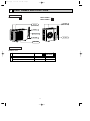
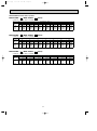
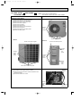
SPLIT-TYPE, HEAT PUMP AIR CONDITIONERS
No. OB322
SERVICE MANUAL
Wireless type
Models
MUH-A18WV MUH-A24WV MUH-A30WV -
E1
E1
E1
CONTENTS
Indication of model name
MUH-A18WV -
E1
1. TECHNICAL CHANGES ····································3
2. PART NAMES AND FUNCTIONS······················6
3. SPECIFICATION·················································7
4. NOISE CRITERIA CURVES ·······························8
5. OUTLINES AND DIMENSIONS ·························9
6. WIRING DIAGRAM ··········································10
7. REFRIGERANT SYSTEM DIAGRAM ··············12
8. PERFORMANCE CURVES ······························15
9. MICROPROCESSOR CONTROL ····················25
10. SERVICE FUNCTIONS·····································29
11. TROUBLESHOOTING ······································29
12. DISASSEMBLY INSTRUCTIONS·····················39
13. PARTS LIST······················································43
NOTE:
•This service manual describes technical data of outdoor unit.
As for indoor unit MSH-A18WV- E1 , MSH-A24WV- E1 and MSH-A30Vrefer to the service manual OB321.
E1
,
OB322-1.qxp
03.11.13 4:06 PM
Page 2
03.11.13 4:06 PM
1
Page 3
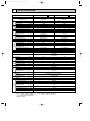
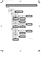
TECHNICAL CHANGES
MUH-18RV - E2 ➔MUH-A18WV - E1
1. Refrigerant has changed. (R22➔R410A)
2. Refrigerant system diagram has changed.
• Compressor, stop valve and 4-way valve have changed.
• Diameter of stop valve has changed. (Gas: [15.88➔[12.7)
• Accumulator has removed and high pressure receiver has been added.
3. Oil separator has been added.
MUH-24RV - E1 ➔MUH-A24WV - E1
1. Dimension of outdoor unit has changed.
2. Refrigerant has changed. (R22➔R410A)
3. Refrigerant system diagram has changed.
• Diameter of stop valve has changed. (Liquid: [9.52➔[6.35)
• Accumulator has removed and high pressure receiver has been added.
MUH-30RV - E1 ➔MUH-A30WV - E1
1. Dimension of outdoor unit has changed.
2. Refrigerant has changed. (R22➔R410A)
3. Refrigerant system diagram has changed.
• Accumulator has removed and high pressure receiver has been added.
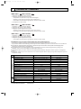
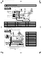
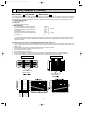
INFORMATION FOR THE AIR CONDITIONER WITH R410A REFRIGERANT
• This room air conditioner adopts an HFC refrigerant (R410A) which never destroys the ozone layer.
• Pay particular attention to the following points, though the basic installation procedure is same as that for R22 conditioners.
1 As R410A has working pressure approximate 1.6 times as high as that of R22, some special tools and piping parts/
materials are required. Refer to the table below.
2 Take sufficient care not to allow water and other contaminations to enter the R410A refrigerant during storage and
installation, since it is more susceptible to contaminations than R22.
3 For refrigerant piping, use clean, pressure-proof parts/materials specifically designed for R410A. (Refer to 2. Refrigerant
piping.)
4 Composition change may occur in R410A since it is a mixed refrigerant. When charging, charge liquid refrigerant to prevent
composition change.
New refrigerant
Previous refrigerant
R410A
R22
Refrigerant
Composition (Ratio)
HFC-32: HFC-125 (50%:50%)
R22 (100%)
Refrigerant handling
Pseudo-azeotropic refrigerant
Single refrigerant
Not included
Included
A1/A1
A1
72.6
86.5
Boiling point (:)
-51.4
-40.8
Steam pressure [25:](Mpa)
1.557
0.94
Chlorine
Refrigerant
Safety group (ASHRAE)
Molecular weight
64
44.4
Non combustible
Non combustible
ODP w1
0
0.055
GWP w2
1730
1700
From liquid phase in cylinder
Gas phase
Possible
Possible
Kind
Incompatible oil
Compatible oil
Color
Non
Light yellow
Smell
Non
Non
Saturated steam density [25:](Kg/K)
Combustibility
Refrigerant charge method
oil
Additional charge on leakage
Refrigerating
OB322-1.qxp
w1 :Ozone Destruction Parameter : based on CFC-11
w2 :Global Warmth Parameter
: based on CO2
3
OB322-1.qxp
03.11.13 4:06 PM
Page 4
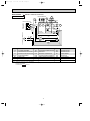
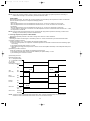
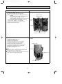
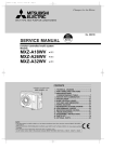
Compressor
New Specification
Current Specification
The incompatible refrigerating oil easily separates from
Since refrigerant and refrigerating oil are compatible each,
refrigerant and is in the upper layer inside the suction muffler. refrigerating oil backs to the compressor through the lower
Raising position of the oil back hole enables to back the
position oil back hole.
refrigerating oil of the upper layer to flow back to the
compressor.
Suction muffler
Suction muffler
Oil back hole
Compressor
Compressor
Refrigerating oil
Oil back hole
Refrigerating oil /Refrigerant
Refrigerant
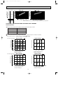
NOTE : The unit of pressure has been changed to MPa on the international system of units(SI unit system).
f [Gauge])
The conversion factor is: 1(MPa [Gauge]) =10.2(kgf/f
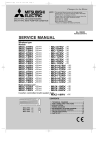
Conversion chart of refrigerant temperature and pressure
(MPa [Gauge])
4.0
Saturated liquid pressure
3.5
R410A
3.0
R22
2.5
2.0
NOTE : The unit of pressure has been changed to MPa on the
international system of units(SI unit system).
1.5
1.0
f [Gauge])
The conversion factor is: 1(MPa [Gauge]) =10.2(kgf/f
0.5
0.0
-0.5
-30 -20 -10
0
10
20
30
40
50
60
(:)
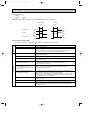
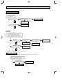
1.Tools dedicated for the air conditioner with R410A refrigerant
The following tools are required for R410A refrigerant. Some R22 tools can be substituted for R410A tools.
The diameter of the service port on the stop valve in outdoor unit has been changed to prevent any other refrigerant being
charged into the unit. Cap size has been changed from 7/16 UNF with 20 threads to 1/2 UNF with 20 threads.
R410A tools
Description
Can R22 tools be used?
R410A has high pressures beyond the measurement range of existing
gauges. Port diameters have been changed to prevent any other refrigerant
from being charged into the unit.
Gauge manifold
No
Charge hose
No
Gas leak detector
No
Hose material and cap size have been changed to improve the pressure
resistance.
Dedicated for HFC refrigerant.
Yes
6.35 mm and 9.52 mm
No
12.7 mm and 15.88 mm
Flare tool
Yes
Clamp bar hole has been enlarged to reinforce the spring strength in the tool.
Flare gauge
Vacuum pump
adapter
Electronic scale for
refrigerant charging
New
Provided for flaring work (to be used with R22 flare tool).
Provided to prevent the back flow of oil. This adapter enables you to use
vacuum pumps.
It is difficult to measure R410A with a charging cylinder because the
refrigerant bubbles due to high pressure and high-speed vaporization
Torque wrench
New
New
No : Not Substitutable for R410A
Yes : Substitutable for R410A
4
OB322-1.qxp
03.11.13 4:06 PM
Page 5
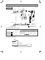
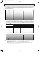
2.Refrigerant piping
1 Specifications
Use the refrigerant pipes that meet the following specifications.
Outside diameter
Pipe
For liquid
For gas
mm
Wall
thickness
6.35
0.8 mm
9.52
0.8 mm
Heat resisting foam plastic
12.7
0.8 mm
Specific gravity 0.045 Thickness 8 mm
15.88
1.0 mm
Insulation material
• Use a copper pipe or a copper-alloy seamless pipe with a thickness of 0.8 mm (6.35, 9.52, 12.7), 1.0 mm (15.88).
Never use any pipe with a thickness less than 0.8 mm (6.35, 9.52, 12.7), 1.0 mm (15.88), as the pressure resistance is
insufficient.
2 Flaring work and flare nut
Flaring work for R410A pipe differs from that for R22 pipe.
For details of flaring work, refer to Installation manual “FLARING WORK”.
Dimension of flare nut
Pipe diameter
mm
R410A
R22
6.35
17
17
9.52
22
22
12.7
26
24
15.88
29
27
3.Refrigerant oil
Apply the special refrigeration oil (accessories: packed with indoor unit) to the flare and the union seat surfaces.
4.Air purge
• Do not discharge the refrigerant into the atmosphere.
Take care not to discharge refrigerant into the atmosphere during installation, reinstallation, or repairs to the refrigerant
circuit.
• Use the vacuum pump for air purging for the purpose of environmental protection.
5.Additional charge
For additional charging, charge the refrigerant from liquid phase of the gas cylinder.
If the refrigerant is charged from the gas phase, composition change may occur in the refrigerant inside the cylinder and the
outdoor unit. In this case, ability of the refrigerating cycle decreases or normal operation can be impossible. However,
charging the liquid refrigerant all at once may cause the compressor to be locked. Thus, charge the refrigerant slowly.
Union
Stop valve
Indoor unit
Liquid pipe
Outdoor unit
Gas pipe
Refrigerant gas
cylinder
operating valve
Service port
Gauge manifold
valve (for R410A)
Charge hose (for R410A)
Refrigerant gas cylinder
for R410A with siphon
Refrigerant (liquid)
Electronic scale for refrigerant charging
5
OB322-1.qxp
2
03.11.13 4:06 PM
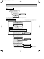
Page 6
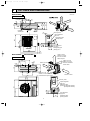
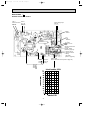
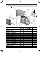
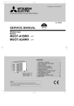
PART NAMES AND FUNCTIONS
OUTDOOR UNIT
MUH-A18WV -
MUH-A24WV MUH-A30WV -
E1
E1
E1
Air inlet
(back and side)
Air inlet
(back and side)
Piping
Drainage hose
Air outlet
Air outlet
Drain outlet
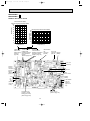
ACCESSORIES
Outdoor unit
MUH-A18WV1
2
Drain socket
Drain cap {33
Drain cap {16
E1
MUH-A24WVMUH-A30WV1
2
—
1
2
1
6
E1
E1
03.11.13 4:06 PM
3
Page 7
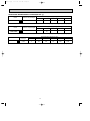
SPECIFICATION
Outdoor model
Function
MUH-A18WV -
Electrical
Capacity
data
Special
remarks
Fan
Compressor
motor
Capacity
kW
Dehumidification
r/h
Air flow(High)
K /h
Starting current
A
Compressor motor current
A
Fan motor current
A
Coefficient of performance(C.O.P)
Model
Output
W
Winding
"
resistance(at20:)
Model
Winding
"
resistance(at20:)
Dimensions WOHOD
mm
Weight
kg
Sound level(High)
dB
Fan speed(High)
rpm
Fan speed regulator
Refrigerant filling
kg
capacity(R410A)
Refrigerating oil (Model)
cc
Thermistor RT61(at0:)
k"
Outdoor model
Function
Electrical
Capacity
data
Compressor
Fan
motor
Cooling
Single phase
230V, 50Hz
E1
Heating
Single phase
230V, 50Hz
6.3
3.2
5.2
—
5.0
2.5
7.2
—
2,196
37
2,760
74
9.81
6.84
7.54
10.12
0.39
0.58
2.61
3.23
2.81
RN196VHSHT
1,300
C-R 1.80
C-S 3.00
RA6V50-OG
WHT-BLK 116
BLK-RED 111
850o605o290
47
52
828
1
2.90
NN29VBAHT
1,900
C-R 0.80
C-S 1.64
RA6V85-AB
WHT-BLK 63 BLK-YLW 30
YLW-RED 63
840o850o330
74
53
730
1
1.75
2.15
520 (NEO22)
33.18
1,200 (NEO22)
33.18
MUH-A30WV -
E1
Cooling
Heating
Single phase
230V, 50Hz
Power supply
Capacity
kW
Dehumidification
R/h
Air flow(High/Low w)
K /h
Starting current
A
Compressor motor current
A
Fan motor current
A
Coefficient of performance(C.O.P)
Model
Output
W
Winding
"
resistance(at20:)
Model
Winding
"
resistance(at20:)
Dimensions WOHOD
mm
Weight
kg
Sound level(High)
dB
Fan speed(High/Loww )
rpm
Fan speed regulator
Refrigerant filling
kg
capacity(R410A)
Refrigerating oil (Model)
cc
Thermistor RT61(at0:)
k"
Thermistor RT62(at25:)
k"
Thermistor RT63(at0:)
k"
MUH-A24WV -
E1
Heating
Cooling
Power supply
Special
remarks
OB322-1.qxp
8.5
4.6
2,940/1,470 w
9.4
—
2,940/1,470 w
90
13.85
14.62
0.57
2.52-2.40
2.73-2.70
NN37VAAHT
2,500
C-R 0.64
C-S 1.63
RA6V75-AB
WHT-BLK 62.8 BLK-YLW 55.9
YLW-RED 26.0
840o850o330
77
55
805/435 w
2
2.30
1,300 (NEO 22)
33.18
231.44
33.18
NOTE: Test conditions are based on JIS C 9612.
Cooling : Indoor DB27°C WB19°C
Heating : Indoor DB20°C WB 15.5°C
Outdoor DB35°C WB(24°C)
Outdoor DB 7°C WB 6°C
Indoor-Outdoor piping length 5m
w Reference value
7
OB322-1.qxp
03.11.13 4:06 PM
Page 8
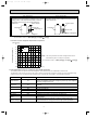
NOISE CRITERIA CURVES
4
MUH-A24WV- E1
MUH-A18WV- E1
FAN SPEED SPL(dB(A))
High
52
Test conditions,
Cooling : Dry-bulb temperature 35: Wet-bulb temperature 24:
Heating : Dry-bulb temperature 7: Wet-bulb temperature 6:
90
80
70
NC-70
60
NC-60
50
NC-50
40
NC-40
30
NC-30
20
10
APPROXIMATE
THRESHOLD OF
HEARING FOR
CONTINUOUS
NOISE
63
125
NC-20
250
500
1000
2000
4000
70
NC-70
60
NC-60
50
NC-50
40
NC-40
30
NC-30
20
APPROXIMATE
THRESHOLD OF
HEARING FOR
CONTINUOUS
NOISE
63
125
NC-20
250
500
1000
LINE
OUTDOORUNIT
55
1m
OCTAVE BAND SOUND PRESSURE LEVEL, dB re 0.0002 MICRO BAR
Test conditions,
Cooling : Dry-bulb temperature 35: Wet-bulb temperature 24:
Heating : Dry-bulb temperature 7: Wet-bulb temperature 6:
90
MICROPHONE
80
70
NC-70
60
NC-60
50
NC-50
40
NC-40
30
NC-30
20
10
APPROXIMATE
THRESHOLD OF
HEARING FOR
CONTINUOUS
NOISE
63
125
NC-20
250
500
1000
2000
4000
2000
4000
BAND CENTER FREQUENCIES, Hz
MUH-A30WV- E1
High
53
80
10
8000
BAND CENTER FREQUENCIES, Hz
FAN SPEED SPL(dB(A))
LINE
Test conditions,
Cooling : Dry-bulb temperature 35: Wet-bulb temperature 24:
Heating : Dry-bulb temperature 7: Wet-bulb temperature 6:
90
OCTAVE BAND SOUND PRESSURE LEVEL, dB re 0.0002 MICRO BAR
OCTAVE BAND SOUND PRESSURE LEVEL, dB re 0.0002 MICRO BAR
High
FAN SPEED SPL(dB(A))
LINE
8000
BAND CENTER FREQUENCIES, Hz
8
8000
03.11.13 4:06 PM
5
Page 9
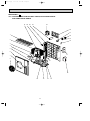
OUTLINES AND DIMENSIONS
MUH-A18WV- E1
OUTDOOR UNIT
355
350
Air in
35
Drainage
hole [16.2
100mm or more
Unit: mm
20
Drainage
3holes [33
re
r mo
mo
500m
50
Air out
re
r mo
mo
m
0
0
1
345
Air in
310
290
248
90
100m
mo
r mo
re
30
350
mm
or m
ore
Service panel
20
100
157
35-
292
30-
605
Liquid refrigerant
pipe joint
Refregerant pipe
(flared) [6.35
183
161
500
850
MUH-A24WV- E1
Gas refregerant
pipe joint
Refregerant pipe
(flared) [12.7
74
Open as a rule
500mm or more if
the front and both
sides are open
MUH-A30WV- E1
OUTDOOR UNIT
515
100mm or more
200mm or more if
there are obstacles
to both sides
299
40
66
360
330
51
34
100mm or more
500
840
121
80
Open as a rule
500mm or more if the back,
both sides and top are open
350mm or more
Service panel
155
90
35-
30-
850
Liquid refrigerant
pipe joint
Refrigerant pipe
(flared) [6.35 (MUH-A24WV)
[9.52 (MUH-A30WV)
430
OB322-1.qxp
198
9
Gas refrigerant
pipe joint
Refrigerant pipe
(flared) [15.88
OB322-1.qxp
03.11.13 4:06 PM
6
Page 10
WIRING DIAGRAM
MUH-A18WV - E1 MODEL WIRING DIAGRAM
OUTDOOR UNIT
RED
ORN
WHT
BLK
CN721
SR62
CN661
F61
DSAR
N
POWER SUPPLY
~ /N
230V 50Hz
1
2
3
NR61
RED
TO
INDOOR UNIT
N BLK
CONNECTING
12V
TB1 BRN
CIRCUIT BREAKER
L
BRN
CN730
TB2
3
MF
21S4
RT61
T61
BLU
1 2 3 4
CN711
WHT
1
BLK
SR61
2
RED
3
C65
52C
TAB20
PE
GRN/YLW
4
3
DEICER P.C.BOARD
C1
BLU
WHT
RED
S
BLK
C
MC
R
SYMBOL
NAME
C1
COMPRESSOR CAPACITOR
MF
C65
OUTDOOR FAN CAPACITOR
NR61
VARISTOR
21S4
R.V. COIL
RT61
DEFROST THERMISTOR
52C
COMPRESSOR CONTACTOR
DSAR
NAME
SYMBOL
SURGE ABSORBER
F61
FUSE (2A)
MC
COMPRESOR (INNER PROTECTOR)
NAME
SYMBOL
OUTDOOR FAN MOTOR (INNER PROTECTOR) TB1,TB2 TERMINAL BLOCK
SR61,SR62 SOLID STATE RELAY
TRANSFORMER
T61
NOTES: 1.About the indoor side electric wiring refer to the indoor unit electric wiring diagram for servicing.
2.Use copper conductors only. (For field wiring)
3.Symbols below indicate.
: Connector
: Terminal block
MUH-A24WV - E1
OUTDOOR UNIT
MODEL WIRING DIAGRAM
YLW
BLK
WHT
ORN
RED
MF
DSAR
6 5 4 3 2 1
YLW
BLK
WHT
BRN
RT61
TO INDOOR UNIT CONNECTING
12V
L TB1
1 2 3
CN661
X62
N
X52
SR61
PE
RED
ORN
DEICER
P.C. BOARD
C2
21S4
NO
CN730 7
5
3
F61
1
T61
NR61
BRN
BLU
N
TB2
BRN 3
4
WHT
C
52C
C1
BLU
RED
S MC R
BLK
BLU
A1
52C
A2
SYMBOL
NAME
C1
COMPRESSOR CAPACITOR
C2
OUTDOOR FAN CAPACITOR
DSAR
CN711 CN721
1
2
X62
3
COM NO
TAB52
X52
COM
GRN/YLW
POWER SUPPLY
~ /N 230V 50Hz
CIRCUIT BREAKER
3
VG79B553H01
BLU
RED
BLU
SURGE ABSORBER
F61
FUSE (3.15A)
MC
COMPRESSOR (INNER PROTECTOR)
MF
OUTDOOR FAN MOTOR (INNER PROTECTOR)
NR61
VARISTOR
RT61
DEFROST THERMISTOR
SR61
SOLID STATE RELAY
TB1
TERMINAL BLOCK
TB2
TERMINAL BLOCK
T61
TRANSFORMER
X52
CONTACTOR
X62
R. V. COIL RELAY
21S4
R. V. COIL
52C
COMPRESSOR CONTACTOR
SG79J883H01
NOTES: 1.Use copper conductors only (For field wiring).
2.Since the indoor and outdoor unit connecting wires have polarity, connect them according to the numbers (3,N).
3.Symbols below indicate.
: Terminal block,
: Connector
10
03.11.13 4:06 PM
Page 11
6 5 4 3 2 1
YLW
BLK
WHT
6
L
TB1
CN662
1 2 3
CN724
SR62
X62
N
X52
SR61
PE
RED
ORN
C2
CN711CN721
1
2
X62
3
COM NO
X52 TAB52
21S4
COM NO
GRN/YLW
POWER SUPPLY
~ /N 230V 50Hz
CIRCUIT BREAKER
CN661
YLW
BLK
WHT
ORN
RED
MF
LEV
DSAR
BRN
MUH-A30WV - E1 MODEL WIRING DIAGRAM
RT61 RT62 RT63
OUTDOOR UNIT
TO INDOOR UNIT CONNECTING
12V
OB322-1.qxp
T61
DEICER
PC BOARD
NR61
CN730 7
5
3
F61
1
BRN
BLU
3
TB2
BRN 1
N
WHT
2
52C
CZ
WHT
C
C1 RED
WHT
BLU
S MC R
BLK
A1
BLU
52C
A2
BLU
RED
BLU
SYMBOL
NAME
SYMBOL
NAME
SYMBOL
MF
NAME
CZ
CZ SURGE ABSRBER
OUTDOOR FAN MOTOR (INNER PROTECTOR)
TB1
TERMINAL BLOCK
C1
COMPRESSOR CAPACITOR
NR61
VARISTOR
TB2
TERMINAL BLOCK
C2
OUTDOOR FAN CAPACITOR
RT61
DEFROST THERMISTOR
T61
TRANSFORMER
SURGE ABSORBER
RT62
DISCHARGE TEMPERATURE THERMISTOR
X52
CONTACTOR
DSAR
F61
FUSE(3.15A)
RT63
AMBIENT TEMPERATURE THERMISTOR
X62
R.V. COIL RELAY
LEV
EXPANSION VALVE COIL
SR61
SOLID STATE RELAY
21S4
R.V. COIL
MC
COMPRESSOR (INNER PROTECTOR)
SR62
SOLID STATE RELAY
52C
COMPRESSOR CONTACTOR
NOTE 1. Use copper conductors only (For field wiring).
2. Since the indoor and outdoor unit connecting wires have polarity, connect them according to the numbers (3,N).
3. Symbols below indicate.
/: Terminal block,
: Connector
11
SG79J882H01
OB322-1.qxp
7
03.11.13 4:06 PM
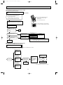
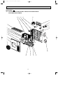
Page 12
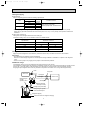
REFRIGERANT SYSTEM DIAGRAM
MUH-A18WV - E1
OUTDOOR UNIT
Unit:mm
4- way valve
Refrigerant pipe [12.7
(with heat insulator)
Oil separator
#100
Stop valve
(with service port)
Defrost
thermistor
RT61
Flared connection
Outdoor
heat
exchanger
Capillary tube
[2.5o[0.6o1,000
Compressor
Capillary tube
[3.0o[1.6o750
(2 pcs)
Flared connection
Capillary tube
[3.0o[1.6o450
Receiver
Stop
Refrigerant pipe[6.35 valve
(with heat insulator)
Strainer
#100
R.V. coil
Heating ON
Cooling OFF
Capillary tube
Check valve [3.0o[1.6o300
Refrigerant flow in cooling
Refrigerant flow in heating
MUH-A24WV - E1
OUTDOOR UNIT
Refrigerant pipe [15.88
(with heat insulator)
4- way valve
Stop valve
(with service port)
Flared connection
Muffler
#100
Muffler
Compressor
Flared connection
Outdoor
heat
exchanger
Defrost
thermistor
RT61
Capillary tube
[3.0X[2.0X550
Receiver
Stop valve
Refrigerant pipe [6.35
(with heat insulator)
R.V. coil
Capillary tube
Strainer
Heating ON
[3.0X[2.0X650
#100
Cooling OFF
Check valve
Refrigerant flow in cooling
Refrigerant flow in heating
12
OB322-1.qxp
03.11.13 4:06 PM
Page 13
MUH-A30WV - E1
OUTDOOR UNIT
Unit:mm
Muffler
4-way valve #100
Refrigerant pipe [15.88
(with heat insulator)
Stop valve
(with service port)
Flared connection
Outdoor
heat
exchanger
Discharge
temperature
thermistor
RT62
Defrost
thermistor
RT61
Muffler
Compressor
Flared connection
Strainer
Receiver #100
Stop valve
LEV
Ambient
temperature
thermistor
RT63
Strainer
#100
R.V. coil
heating ON
cooling OFF
Capillary tube
[3.6✕[2.4✕50
Refrigerant pipe [9.52
(with heat insulator)
Refrigerant flow in cooling
Refrigerant flow in heating
MAX. REFRIGERANT PIPING LENGTH
Refrigerant piping
Model
Piping size O.D : mm
Max. length : m
Gas
A
MUH-A18WV -
6.35
25
E1
MUH-A30WV -
E1
Indoor unit
Outdoor unit
12.7
E1
MUH-A24WV -
Liquid
Length of connecting pipe : m
15.88
Gas 0.43
Gas 0
Liquid 0.5
Liquid 0
9.52
30
MAX. HEIGHT DIFFERENCE
Indoor
unit
wMax. Height
difference:
10m(MSH-A18/A24WV)/
15m(MSH-A30WV)
Refrigerant Piping
Max. Length
A
Outdoor unit
w Height difference should be within 10m(MSH-A18/A24WV)/
15m(MSH-A30WV) regardless of which unit, indoor or outdoor position is high.
13
OB322-1.qxp
03.11.13 4:06 PM
Page 14
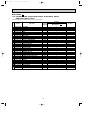
ADDITIONAL REFRIGERANT CHARGE(R410A : g)
Refrigerant piping length (one way)
Outdoor unit precharged
Model
MUH-A18WV -
1,750
E1
7m
10m
15m
20m
25m
0
60
160
260
360
Calculation : Xg=20g/m ✕ (Refrigerant piping length (m)–7)
Refrigerant piping length (one way)
Outdoor unit precharged
Model
MUH-A24WV -
2,150
E1
7m
10m
15m
20m
25m
0
60
160
260
360
Calculation : Xg=20g/m ✕ (Refrigerant piping length (m)–7)
Model
MUH-A30WV -
E1
Refrigerant piping length (one way)
Outdoor unit
precharged
7m
10m
15m
20m
25m
30m
2,300
0
165
440
715
990
1,265
Calculation : Xg=55g/mo(Refrigerant piping length(m)-7)
14
OB322-1.qxp
03.11.13 4:06 PM
8
Page 15
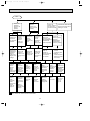
PERFORMANCE CURVES
MUH-A18WV - E1
MUH-A24WV - E1
MUH-A30WV - E1
The standard data contained in these specifications apply only to the operation of the air conditioner under normal conditions,
since operating conditions vary according to the areas where these units are installed. The following information has been provided to clarify the operating characteristics of the air conditioner under the conditions indicated by the performance curve.
(1) GUARANTEED VOLTAGE
198 ~ 264V, 50Hz
(2) AIR FLOW
Air flow should be set at MAX.
(3) MAIN READINGS
(1) Indoor intake air wet-bulb temperature :
°CWB
(2) Indoor outlet air wet-bulb temperature :
°CWB
Cooling
(3) Outdoor intake air dry-bulb temperature :
°CDB
(4) Total input:
W
(5) Indoor intake air dry-bulb temperature :
°CDB
Heating
(6) Outdoor intake air wet-bulb temperature :
°CWB
(7) Total input :
W
}
}
Indoor air wet/dry-bulb temperature difference on the left side of the chart on this page and next page shows the difference between the indoor intake air wet/dry-bulb temperature and the indoor outlet air wet/dry-bulb temperature for your
reference at service.
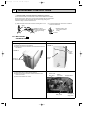
How to measure the indoor air wet-bulb/dry-bulb temperature difference
INDOOR UNIT
OUTDOOR UNIT
Wet-and dry-bulb
thermometers
Wet-and dry-bulb
thermometers
12.8
17.2 19.2
11.6
15.6 17.4
10.5
14.1 15.6
9.5
12.6 13.9
8.5
11.2 12.4
7.5
9.8 10.8
MSH-A30WV - E1
MUH-A30WV - E1
3.
4.
5.
6.
7.
MSH-A24WV - E1
MUH-A24WV - E1
2.
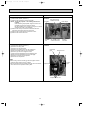
Attach at least 2 sets of wet-and dry-bulb thermometers to the indoor air intake as shown in the figure, and at least 2 sets
of wet-and dry-bulb thermometers to the indoor air outlet. The thermometers must be attached to the position where air
speed is high.
Attach at least 2 sets of wet-and dry-bulb thermometers to the outdoor air intake.
Cover the thermometers to prevent direct rays of the sun.
Check that the air filter is cleaned.
Open windows and doors of room.
Press the EMERGENCY OPERATION switch once(twice) to start the EMERGENCY COOL(HEAT) MODE.
When system stabilizes after more than 15 minutes, measure temperature and take an average temperature.
10 minutes later, measure temperature again and check that the temperature does not change.
MSH-A18WV - E1
MUH-A18WV - E1
1.
15
03.11.13 4:06 PM
36.8 38.4
24.5
34.0 35.5
22.5
31.1 32.5
20.4
28.3 29.6
18.4
25.5 26.6
16.3
22.6 23.6
19.8 20.7
12.3
17.0 17.7
Page 16
MSH-A30WV - E1
MUH-A30WV - E1
14.3
MSH-A24WV - E1
MUH-A24WV - E1
26.6
MSH-A18WV - E1
MUH-A18WV - E1
OB322-1.qxp
NOTE:The above curves are for the heating operation without any frost.
OUTDOOR LOW PRESSURE AND OUTDOOR UNIT CURRENT
COOL operation
1 Both indoor and outdoor unit are under the same temperature/humidity condition.
Dry-bulb temperature
Relative humidity(%)
20
50
25
60
30
70
2 Air flow should be set at MAX.
3 The unit of pressure has been changed to MPa on the international system of units(SI unit system).
f [Gauge])
The conversion factor is : 1(MPa [Gauge]) =10.2(kgf/f
13
1.3
12
1.2
11
1.1
10
1.0
9
0.9
8
0.8
7
0.7
15
MUH-A18WV - E1
230V
18 20
50
25
60
30 32
70(%)
(kgf/F[Gauge])(MPa[Gauge])
11
1.1
10
1.0
9
0.9
8
0.8
7
0.7
6
0.6
15
6
5
15
35(:)
11
Outdoor unit current (A)
230V
25
60
18 20
50
25
60
30 32
70(%)
35(:)
Ambient temperature(˚C)
Ambient humidity(%)
MUH-A24WV - E1
18 20
50
230V
7
Ambient temperature(˚C)
Ambient humidity(%)
Outdoor low pressure
MUH-A18WV - E1
8
Outdoor unit current (A)
Outdoor low pressure
(kgf/F[Gauge])(MPa[Gauge])
30 32
70(%)
MUH-A24WV - E1
230V
10
9
8
35(:)
Ambient temperature(˚C)
Ambient humidity(%)
Ambient temperature(˚C)
Ambient humidity(%)
16
03.11.13 4:06 PM
Page 17
(kgf/F[Gauge])(MPa[Gauge])
MUH-A30WV - E1
16
230V
10
10
9
9
8
8
7
7
6
6
5
5
15
18 20
50
25
60
30 32
70(%)
Outdoor unit current(A)
Outdoor low pressure
MUH-A30WV - E1
11
11
230V
15
14
13
12
11
10
15
35(:)
Ambient temperature(˚C)
Ambient humidity(%)
18 20
50
25
60
30 32
70(%)
Ambient temperature(˚C)
Ambient humidity(%)
HEAT operation
Condition indoor:Dry bulb temperature 20.0°C
Wet bulb temperature 14.5°C
Outdoor:Dry bulb temperature 7,15,20°C
Wet bulb temperature 6,12,14.5°C
MUH-A18WV - E1
14
9
Outdoor unit current (A)
Outdoor unit current (A)
10
230V
8
7
5
7
10
15
20 21
230V
19
18
17
16
5
7
10
15
20 21
230V
13
12
Ambient temperature(˚C)
MUH-A30WV - E1
20
MUH-A24WV - E1
11
25(:)
Ambient temperature(˚C)
Outdoor unit current(A)
OB322-1.qxp
25 (:)
Ambient temperature(˚C)
17
35(:)
OB322-1.qxp
03.11.13 4:06 PM
Page 18
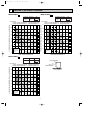
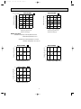
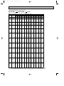
PERFORMANCE DATA COOL operation
MSH-A18WV - E1 : MUH-A18WV - E1 (230V)
CAPACITY : 5.0(KW) SHF : 0.65
INDOOR INDOOR
DB(:) WB(:)
21
18
21
20
22
18
22
20
22
22
23
18
23
20
23
22
24
18
24
20
24
22
24
24
25
18
25
20
25
22
25
24
26
18
26
20
26
22
26
24
26
26
27
18
27
20
27
22
27
24
27
26
28
18
28
20
28
22
28
24
28
26
29
18
29
20
29
22
29
24
29
26
30
18
30
20
30
22
30
24
30
26
31
18
31
20
31
22
31
24
31
26
32
18
32
20
32
22
32
24
32
26
NOTE
Q
5.88
6.13
5.88
6.13
6.38
5.88
6.13
6.38
5.88
6.13
6.38
6.70
5.88
6.13
6.38
6.70
5.88
6.13
6.38
6.70
6.90
5.88
6.13
6.38
6.70
6.90
5.88
6.13
6.38
6.70
6.90
5.88
6.13
6.38
6.70
6.90
5.88
6.13
6.38
6.70
6.90
5.88
6.13
6.38
6.70
6.90
5.88
6.13
6.38
6.70
6.90
INPUT : 1780(W)
OUTDOOR DB(:)
21
25
27
30
SHC SHF INPUT Q SHC SHF INPUT Q SHC SHF INPUT Q SHC SHF INPUT
2.76 0.47 1424 5.63 2.64 0.47 1495 5.40 2.54 0.47 1566 5.20 2.44 0.47 1638
2.14 0.35 1495 5.88 2.06 0.35 1584 5.70 2.00 0.35 1620 5.50 1.93 0.35 1691
3.00 0.51 1424 5.63 2.87 0.51 1495 5.40 2.75 0.51 1566 5.20 2.65 0.51 1638
2.39 0.39 1495 5.88 2.29 0.39 1584 5.70 2.22 0.39 1620 5.50 2.15 0.39 1691
1.72 0.27 1549 6.15 1.66 0.27 1647 6.00 1.62 0.27 1691 5.75 1.55 0.27 1762
3.23 0.55 1424 5.63 3.09 0.55 1495 5.40 2.97 0.55 1566 5.20 2.86 0.55 1638
2.63 0.43 1495 5.88 2.53 0.43 1584 5.70 2.45 0.43 1620 5.50 2.37 0.43 1691
1.98 0.31 1549 6.15 1.91 0.31 1647 6.00 1.86 0.31 1691 5.75 1.78 0.31 1762
3.47 0.59 1424 5.63 3.32 0.59 1495 5.40 3.19 0.59 1566 5.20 3.07 0.59 1638
2.88 0.47 1495 5.88 2.76 0.47 1584 5.70 2.68 0.47 1620 5.50 2.59 0.47 1691
2.23 0.35 1549 6.15 2.15 0.35 1647 6.00 2.10 0.35 1691 5.75 2.01 0.35 1762
1.54 0.23 1620 6.45 1.48 0.23 1709 6.30 1.45 0.23 1762 6.10 1.40 0.23 1851
3.70 0.63 1424 5.63 3.54 0.63 1495 5.40 3.40 0.63 1566 5.20 3.28 0.63 1638
3.12 0.51 1495 5.88 3.00 0.51 1584 5.70 2.91 0.51 1620 5.50 2.81 0.51 1691
2.49 0.39 1549 6.15 2.40 0.39 1647 6.00 2.34 0.39 1691 5.75 2.24 0.39 1762
1.81 0.27 1620 6.45 1.74 0.27 1709 6.30 1.70 0.27 1762 6.10 1.65 0.27 1851
3.94 0.67 1424 5.63 3.77 0.67 1495 5.40 3.62 0.67 1566 5.20 3.48 0.67 1638
3.37 0.55 1495 5.88 3.23 0.55 1584 5.70 3.14 0.55 1620 5.50 3.03 0.55 1691
2.74 0.43 1549 6.15 2.64 0.43 1647 6.00 2.58 0.43 1691 5.75 2.47 0.43 1762
2.08 0.31 1620 6.45 2.00 0.31 1709 6.30 1.95 0.31 1762 6.10 1.89 0.31 1851
1.31 0.19 1709 6.70 1.27 0.19 1798 6.60 1.25 0.19 1851 6.40 1.22 0.19 1905
4.17 0.71 1424 5.63 3.99 0.71 1495 5.40 3.83 0.71 1566 5.20 3.69 0.71 1638
3.61 0.59 1495 5.88 3.47 0.59 1584 5.70 3.36 0.59 1620 5.50 3.25 0.59 1691
3.00 0.47 1549 6.15 2.89 0.47 1647 6.00 2.82 0.47 1691 5.75 2.70 0.47 1762
2.35 0.35 1620 6.45 2.26 0.35 1709 6.30 2.21 0.35 1762 6.10 2.14 0.35 1851
1.59 0.23 1709 6.70 1.54 0.23 1798 6.60 1.52 0.23 1851 6.40 1.47 0.23 1905
4.41 0.75 1424 5.63 4.22 0.75 1495 5.40 4.05 0.75 1566 5.20 3.90 0.75 1638
3.86 0.63 1495 5.88 3.70 0.63 1584 5.70 3.59 0.63 1620 5.50 3.47 0.63 1691
3.25 0.51 1549 6.15 3.14 0.51 1647 6.00 3.06 0.51 1691 5.75 2.93 0.51 1762
2.61 0.39 1620 6.45 2.52 0.39 1709 6.30 2.46 0.39 1762 6.10 2.38 0.39 1851
1.86 0.27 1709 6.70 1.81 0.27 1798 6.60 1.78 0.27 1851 6.40 1.73 0.27 1905
4.64 0.79 1424 5.63 4.44 0.79 1495 5.40 4.27 0.79 1566 5.20 4.11 0.79 1638
4.10 0.67 1495 5.88 3.94 0.67 1584 5.70 3.82 0.67 1620 5.50 3.69 0.67 1691
3.51 0.55 1549 6.15 3.38 0.55 1647 6.00 3.30 0.55 1691 5.75 3.16 0.55 1762
2.88 0.43 1620 6.45 2.77 0.43 1709 6.30 2.71 0.43 1762 6.10 2.62 0.43 1851
2.14 0.31 1709 6.70 2.08 0.31 1798 6.60 2.05 0.31 1851 6.40 1.98 0.31 1905
4.88 0.83 1424 5.63 4.67 0.83 1495 5.40 4.48 0.83 1566 5.20 4.32 0.83 1638
4.35 0.71 1495 5.88 4.17 0.71 1584 5.70 4.05 0.71 1620 5.50 3.91 0.71 1691
3.76 0.59 1549 6.15 3.63 0.59 1647 6.00 3.54 0.59 1691 5.75 3.39 0.59 1762
3.15 0.47 1620 6.45 3.03 0.47 1709 6.30 2.96 0.47 1762 6.10 2.87 0.47 1851
2.42 0.35 1709 6.70 2.35 0.35 1798 6.60 2.31 0.35 1851 6.40 2.24 0.35 1905
5.11 0.87 1424 5.63 4.89 0.87 1495 5.40 4.70 0.87 1566 5.20 4.52 0.87 1638
4.59 0.75 1495 5.88 4.41 0.75 1584 5.70 4.28 0.75 1620 5.50 4.13 0.75 1691
4.02 0.63 1549 6.15 3.87 0.63 1647 6.00 3.78 0.63 1691 5.75 3.62 0.63 1762
3.42 0.51 1620 6.45 3.29 0.51 1709 6.30 3.21 0.51 1762 6.10 3.11 0.51 1851
2.69 0.39 1709 6.70 2.61 0.39 1798 6.60 2.57 0.39 1851 6.40 2.50 0.39 1905
5.35 0.91 1424 5.63 5.12 0.91 1495 5.40 4.91 0.91 1566 5.20 4.73 0.91 1638
4.84 0.79 1495 5.88 4.64 0.79 1584 5.70 4.50 0.79 1620 5.50 4.35 0.79 1691
4.27 0.67 1549 6.15 4.12 0.67 1647 6.00 4.02 0.67 1691 5.75 3.85 0.67 1762
3.69 0.55 1620 6.45 3.55 0.55 1709 6.30 3.47 0.55 1762 6.10 3.36 0.55 1851
2.97 0.43 1709 6.70 2.88 0.43 1798 6.60 2.84 0.43 1851 6.40 2.75 0.43 1905
Q : Total capacity (kW)
SHC : Sensible heat capacity (kW)
SHF : Sensible heat factor
INPUT : Total power input (W)
18
DB : Dry-bulb temperature
WB : Wet-bulb temperature
OB322-1.qxp
03.11.13 4:06 PM
Page 19
PERFORMANCE DATA COOL operation
MSH-A18WV - E1 : MUH-A18WV - E1 (230V)
CAPACITY : 5.0(KW) SHF : 0.65
INDOOR INDOOR
DB(:) WB(:)
21
18
21
20
22
18
22
20
22
22
23
18
23
20
23
22
24
18
24
20
24
22
24
24
25
18
25
20
25
22
25
24
26
18
26
20
26
22
26
24
26
26
27
18
27
20
27
22
27
24
27
26
28
18
28
20
28
22
28
24
28
26
29
18
29
20
29
22
29
24
29
26
30
18
30
20
30
22
30
24
30
26
31
18
31
20
31
22
31
24
31
26
32
18
32
20
32
22
32
24
32
26
NOTE
Q
4.90
5.15
4.90
5.15
5.45
4.90
5.15
5.45
4.90
5.15
5.45
5.75
4.90
5.15
5.45
5.75
4.90
5.15
5.45
5.75
6.05
4.90
5.15
5.45
5.75
6.05
4.90
5.15
5.45
5.75
6.05
4.90
5.15
5.45
5.75
6.05
4.90
5.15
5.45
5.75
6.05
4.90
5.15
5.45
5.75
6.05
4.90
5.15
5.45
5.75
6.05
INPUT : 1780(W)
OUTDOOR DB(:)
35
40
SHC SHF INPUT Q SHC SHF INPUT
2.30 0.47 1744 4.50 2.12 0.47 1851
1.80 0.35 1816 4.80 1.68 0.35 1905
2.50 0.51 1744 4.50 2.30 0.51 1851
2.01 0.39 1816 4.80 1.87 0.39 1905
1.47 0.27 1887 5.10 1.38 0.27 1994
2.70 0.55 1744 4.50 2.48 0.55 1851
2.21 0.43 1816 4.80 2.06 0.43 1905
1.69 0.31 1887 5.10 1.58 0.31 1994
2.89 0.59 1744 4.50 2.66 0.59 1851
2.42 0.47 1816 4.80 2.26 0.47 1905
1.91 0.35 1887 5.10 1.79 0.35 1994
1.32 0.23 1958 5.40 1.24 0.23 2047
3.09 0.63 1744 4.50 2.84 0.63 1851
2.63 0.51 1816 4.80 2.45 0.51 1905
2.13 0.39 1887 5.10 1.99 0.39 1994
1.55 0.27 1958 5.40 1.46 0.27 2047
3.28 0.67 1744 4.50 3.02 0.67 1851
2.83 0.55 1816 4.80 2.64 0.55 1905
2.34 0.43 1887 5.10 2.19 0.43 1994
1.78 0.31 1958 5.40 1.67 0.31 2047
1.15 0.19 2029 5.70 1.08 0.19 2118
3.48 0.71 1744 4.50 3.20 0.71 1851
3.04 0.59 1816 4.80 2.83 0.59 1905
2.56 0.47 1887 5.10 2.40 0.47 1994
2.01 0.35 1958 5.40 1.89 0.35 2047
1.39 0.23 2029 5.70 1.31 0.23 2118
3.68 0.75 1744 4.50 3.38 0.75 1851
3.24 0.63 1816 4.80 3.02 0.63 1905
2.78 0.51 1887 5.10 2.60 0.51 1994
2.24 0.39 1958 5.40 2.11 0.39 2047
1.63 0.27 2029 5.70 1.54 0.27 2118
3.87 0.79 1744 4.50 3.56 0.79 1851
3.45 0.67 1816 4.80 3.22 0.67 1905
3.00 0.55 1887 5.10 2.81 0.55 1994
2.47 0.43 1958 5.40 2.32 0.43 2047
1.88 0.31 2029 5.70 1.77 0.31 2118
4.07 0.83 1744 4.50 3.74 0.83 1851
3.66 0.71 1816 4.80 3.41 0.71 1905
3.22 0.59 1887 5.10 3.01 0.59 1994
2.70 0.47 1958 5.40 2.54 0.47 2047
2.12 0.35 2029 5.70 2.00 0.35 2118
4.26 0.87 1744 4.50 3.92 0.87 1851
3.86 0.75 1816 4.80 3.60 0.75 1905
3.43 0.63 1887 5.10 3.21 0.63 1994
2.93 0.51 1958 5.40 2.75 0.51 2047
2.36 0.39 2029 5.70 2.22 0.39 2118
4.46 0.91 1744 4.50 4.10 0.91 1851
4.07 0.79 1816 4.80 3.79 0.79 1905
3.65 0.67 1887 5.10 3.42 0.67 1994
3.16 0.55 1958 5.40 2.97 0.55 2047
2.60 0.43 2029 5.70 2.45 0.43 2118
Q : Total capacity (kW)
SHC : Sensible heat capacity (kW)
Q
4.33
4.63
4.33
4.63
4.93
4.33
4.63
4.93
4.33
4.63
4.93
5.25
4.33
4.63
4.93
5.25
4.33
4.63
4.93
5.25
5.53
4.33
4.63
4.93
5.25
5.53
4.33
4.63
4.93
5.25
5.53
4.33
4.63
4.93
5.25
5.53
4.33
4.63
4.93
5.25
5.53
4.33
4.63
4.93
5.25
5.53
4.33
4.63
4.93
5.25
5.53
SHF : Sensible heat factor
INPUT : Total power input (W)
19
SHC
2.03
1.62
2.21
1.80
1.33
2.38
1.99
1.53
2.55
2.17
1.72
1.21
2.72
2.36
1.92
1.42
2.90
2.54
2.12
1.63
1.05
3.07
2.73
2.31
1.84
1.27
3.24
2.91
2.51
2.05
1.49
3.42
3.10
2.71
2.26
1.71
3.59
3.28
2.91
2.47
1.93
3.76
3.47
3.10
2.68
2.15
3.94
3.65
3.30
2.89
2.38
43
SHF INPUT
0.47 1887
0.35 1958
0.51 1887
0.39 1958
0.27 2029
0.55 1887
0.43 1958
0.31 2029
0.59 1887
0.47 1958
0.35 2029
0.23 2092
0.63 1887
0.51 1958
0.39 2029
0.27 2092
0.67 1887
0.55 1958
0.43 2029
0.31 2092
0.19 2163
0.71 1887
0.59 1958
0.47 2029
0.35 2092
0.23 2163
0.75 1887
0.63 1958
0.51 2029
0.39 2092
0.27 2163
0.79 1887
0.67 1958
0.55 2029
0.43 2092
0.31 2163
0.83 1887
0.71 1958
0.59 2029
0.47 2092
0.35 2163
0.87 1887
0.75 1958
0.63 2029
0.51 2092
0.39 2163
0.91 1887
0.79 1958
0.67 2029
0.55 2092
0.43 2163
DB : Dry-bulb temperature
WB : Wet-bulb temperature
OB322-1.qxp
03.11.13 4:06 PM
Page 20
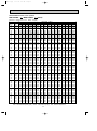
PERFORMANCE DATA COOL operation
MSH-A24WV - E1 : MUH-A24WV - E1 (230V)
CAPACITY : 6.3(KW) SHF : 0.64
INDOOR INDOOR
DB(:) WB(:)
21
18
21
20
22
18
22
20
22
22
23
18
23
20
23
22
24
18
24
20
24
22
24
24
25
18
25
20
25
22
25
24
26
18
26
20
26
22
26
24
26
26
27
18
27
20
27
22
27
24
27
26
28
18
28
20
28
22
28
24
28
26
29
18
29
20
29
22
29
24
29
26
30
18
30
20
30
22
30
24
30
26
31
18
31
20
31
22
31
24
31
26
32
18
32
20
32
22
32
24
32
26
NOTE
Q
7.40
7.72
7.40
7.72
8.03
7.40
7.72
8.03
7.40
7.72
8.03
8.44
7.40
7.72
8.03
8.44
7.40
7.72
8.03
8.44
8.69
7.40
7.72
8.03
8.44
8.69
7.40
7.72
8.03
8.44
8.69
7.40
7.72
8.03
8.44
8.69
7.40
7.72
8.03
8.44
8.69
7.40
7.72
8.03
8.44
8.69
7.40
7.72
8.03
8.44
8.69
INPUT : 2410(W)
OUTDOOR DB(:)
21
25
27
30
SHC SHF INPUT Q SHC SHF INPUT Q SHC SHF INPUT Q SHC SHF INPUT
3.41 0.46 1928 7.09 3.26 0.46 2024 6.80 3.13 0.46 2121 6.55 3.01 0.46 2217
2.62 0.34 2024 7.40 2.52 0.34 2145 7.18 2.44 0.34 2193 6.93 2.36 0.34 2290
3.70 0.50 1928 7.09 3.54 0.50 2024 6.80 3.40 0.50 2121 6.55 3.28 0.50 2217
2.93 0.38 2024 7.40 2.81 0.38 2145 7.18 2.73 0.38 2193 6.93 2.63 0.38 2290
2.09 0.26 2097 7.75 2.01 0.26 2229 7.56 1.97 0.26 2290 7.25 1.88 0.26 2386
4.00 0.54 1928 7.09 3.83 0.54 2024 6.80 3.67 0.54 2121 6.55 3.54 0.54 2217
3.24 0.42 2024 7.40 3.11 0.42 2145 7.18 3.02 0.42 2193 6.93 2.91 0.42 2290
2.41 0.30 2097 7.75 2.32 0.30 2229 7.56 2.27 0.30 2290 7.25 2.17 0.30 2386
4.29 0.58 1928 7.09 4.11 0.58 2024 6.80 3.95 0.58 2121 6.55 3.80 0.58 2217
3.55 0.46 2024 7.40 3.41 0.46 2145 7.18 3.30 0.46 2193 6.93 3.19 0.46 2290
2.73 0.34 2097 7.75 2.63 0.34 2229 7.56 2.57 0.34 2290 7.25 2.46 0.34 2386
1.86 0.22 2193 8.13 1.79 0.22 2314 7.94 1.75 0.22 2386 7.69 1.69 0.22 2506
4.59 0.62 1928 7.09 4.39 0.62 2024 6.80 4.22 0.62 2121 6.55 4.06 0.62 2217
3.86 0.50 2024 7.40 3.70 0.50 2145 7.18 3.59 0.50 2193 6.93 3.47 0.50 2290
3.05 0.38 2097 7.75 2.94 0.38 2229 7.56 2.87 0.38 2290 7.25 2.75 0.38 2386
2.19 0.26 2193 8.13 2.11 0.26 2314 7.94 2.06 0.26 2386 7.69 2.00 0.26 2506
4.89 0.66 1928 7.09 4.68 0.66 2024 6.80 4.49 0.66 2121 6.55 4.32 0.66 2217
4.17 0.54 2024 7.40 4.00 0.54 2145 7.18 3.88 0.54 2193 6.93 3.74 0.54 2290
3.37 0.42 2097 7.75 3.25 0.42 2229 7.56 3.18 0.42 2290 7.25 3.04 0.42 2386
2.53 0.30 2193 8.13 2.44 0.30 2314 7.94 2.38 0.30 2386 7.69 2.31 0.30 2506
1.56 0.18 2314 8.44 1.52 0.18 2434 8.32 1.50 0.18 2506 8.06 1.45 0.18 2579
5.18 0.70 1928 7.09 4.96 0.70 2024 6.80 4.76 0.70 2121 6.55 4.59 0.70 2217
4.48 0.58 2024 7.40 4.29 0.58 2145 7.18 4.17 0.58 2193 6.93 4.02 0.58 2290
3.69 0.46 2097 7.75 3.56 0.46 2229 7.56 3.48 0.46 2290 7.25 3.33 0.46 2386
2.87 0.34 2193 8.13 2.76 0.34 2314 7.94 2.70 0.34 2386 7.69 2.61 0.34 2506
1.91 0.22 2314 8.44 1.86 0.22 2434 8.32 1.83 0.22 2506 8.06 1.77 0.22 2579
5.48 0.74 1928 7.09 5.24 0.74 2024 6.80 5.03 0.74 2121 6.55 4.85 0.74 2217
4.78 0.62 2024 7.40 4.59 0.62 2145 7.18 4.45 0.62 2193 6.93 4.30 0.62 2290
4.02 0.50 2097 7.75 3.87 0.50 2229 7.56 3.78 0.50 2290 7.25 3.62 0.50 2386
3.21 0.38 2193 8.13 3.09 0.38 2314 7.94 3.02 0.38 2386 7.69 2.92 0.38 2506
2.26 0.26 2314 8.44 2.19 0.26 2434 8.32 2.16 0.26 2506 8.06 2.10 0.26 2579
5.77 0.78 1928 7.09 5.53 0.78 2024 6.80 5.31 0.78 2121 6.55 5.11 0.78 2217
5.09 0.66 2024 7.40 4.89 0.66 2145 7.18 4.74 0.66 2193 6.93 4.57 0.66 2290
4.34 0.54 2097 7.75 4.18 0.54 2229 7.56 4.08 0.54 2290 7.25 3.91 0.54 2386
3.55 0.42 2193 8.13 3.41 0.42 2314 7.94 3.33 0.42 2386 7.69 3.23 0.42 2506
2.61 0.30 2314 8.44 2.53 0.30 2434 8.32 2.49 0.30 2506 8.06 2.42 0.30 2579
6.07 0.82 1928 7.09 5.81 0.82 2024 6.80 5.58 0.82 2121 6.55 5.37 0.82 2217
5.40 0.70 2024 7.40 5.18 0.70 2145 7.18 5.03 0.70 2193 6.93 4.85 0.70 2290
4.66 0.58 2097 7.75 4.49 0.58 2229 7.56 4.38 0.58 2290 7.25 4.20 0.58 2386
3.88 0.46 2193 8.13 3.74 0.46 2314 7.94 3.65 0.46 2386 7.69 3.54 0.46 2506
2.96 0.34 2314 8.44 2.87 0.34 2434 8.32 2.83 0.34 2506 8.06 2.74 0.34 2579
6.37 0.86 1928 7.09 6.10 0.86 2024 6.80 5.85 0.86 2121 6.55 5.63 0.86 2217
5.71 0.74 2024 7.40 5.48 0.74 2145 7.18 5.31 0.74 2193 6.93 5.13 0.74 2290
4.98 0.62 2097 7.75 4.80 0.62 2229 7.56 4.69 0.62 2290 7.25 4.49 0.62 2386
4.22 0.50 2193 8.13 4.06 0.50 2314 7.94 3.97 0.50 2386 7.69 3.84 0.50 2506
3.30 0.38 2314 8.44 3.21 0.38 2434 8.32 3.16 0.38 2506 8.06 3.06 0.38 2579
6.66 0.90 1928 7.09 6.38 0.90 2024 6.80 6.12 0.90 2121 6.55 5.90 0.90 2217
6.02 0.78 2024 7.40 5.77 0.78 2145 7.18 5.60 0.78 2193 6.93 5.41 0.78 2290
5.30 0.66 2097 7.75 5.11 0.66 2229 7.56 4.99 0.66 2290 7.25 4.78 0.66 2386
4.56 0.54 2193 8.13 4.39 0.54 2314 7.94 4.29 0.54 2386 7.69 4.15 0.54 2506
3.65 0.42 2314 8.44 3.55 0.42 2434 8.32 3.49 0.42 2506 8.06 3.39 0.42 2579
Q : Total capacity (kW)
SHC : Sensible heat capacity (kW)
SHF : Sensible heat factor
INPUT : Total power input (W)
20
DB : Dry-bulb temperature
WB : Wet-bulb temperature
OB322-1.qxp
03.11.13 4:06 PM
Page 21
PERFORMANCE DATA COOL operation
MSH-A24WV - E1 : MUH-A24WV - E1 (230V)
CAPACITY : 6.3(KW) SHF : 0.64
INDOOR INDOOR
DB(:) WB(:)
21
18
21
20
22
18
22
20
22
22
23
18
23
20
23
22
24
18
24
20
24
22
24
24
25
18
25
20
25
22
25
24
26
18
26
20
26
22
26
24
26
26
27
18
27
20
27
22
27
24
27
26
28
18
28
20
28
22
28
24
28
26
29
18
29
20
29
22
29
24
29
26
30
18
30
20
30
22
30
24
30
26
31
18
31
20
31
22
31
24
31
26
32
18
32
20
32
22
32
24
32
26
NOTE
Q
6.17
6.49
6.17
6.49
6.87
6.17
6.49
6.87
6.17
6.49
6.87
7.25
6.17
6.49
6.87
7.25
6.17
6.49
6.87
7.25
7.62
6.17
6.49
6.87
7.25
7.62
6.17
6.49
6.87
7.25
7.62
6.17
6.49
6.87
7.25
7.62
6.17
6.49
6.87
7.25
7.62
6.17
6.49
6.87
7.25
7.62
6.17
6.49
6.87
7.25
7.62
INPUT : 2410(W)
OUTDOOR DB(:)
35
40
SHC SHF INPUT Q SHC SHF INPUT
2.84 0.46 2362 5.67 2.61 0.46 2506
2.21 0.34 2458 6.05 2.06 0.34 2579
3.09 0.50 2362 5.67 2.84 0.50 2506
2.47 0.38 2458 6.05 2.30 0.38 2579
1.79 0.26 2555 6.43 1.67 0.26 2699
3.33 0.54 2362 5.67 3.06 0.54 2506
2.73 0.42 2458 6.05 2.54 0.42 2579
2.06 0.30 2555 6.43 1.93 0.30 2699
3.58 0.58 2362 5.67 3.29 0.58 2506
2.98 0.46 2458 6.05 2.78 0.46 2579
2.33 0.34 2555 6.43 2.18 0.34 2699
1.59 0.22 2651 6.80 1.50 0.22 2772
3.83 0.62 2362 5.67 3.52 0.62 2506
3.24 0.50 2458 6.05 3.02 0.50 2579
2.61 0.38 2555 6.43 2.44 0.38 2699
1.88 0.26 2651 6.80 1.77 0.26 2772
4.07 0.66 2362 5.67 3.74 0.66 2506
3.50 0.54 2458 6.05 3.27 0.54 2579
2.88 0.42 2555 6.43 2.70 0.42 2699
2.17 0.30 2651 6.80 2.04 0.30 2772
1.37 0.18 2747 7.18 1.29 0.18 2868
4.32 0.70 2362 5.67 3.97 0.70 2506
3.76 0.58 2458 6.05 3.51 0.58 2579
3.16 0.46 2555 6.43 2.96 0.46 2699
2.46 0.34 2651 6.80 2.31 0.34 2772
1.68 0.22 2747 7.18 1.58 0.22 2868
4.57 0.74 2362 5.67 4.20 0.74 2506
4.02 0.62 2458 6.05 3.75 0.62 2579
3.43 0.50 2555 6.43 3.21 0.50 2699
2.75 0.38 2651 6.80 2.59 0.38 2772
1.98 0.26 2747 7.18 1.87 0.26 2868
4.82 0.78 2362 5.67 4.42 0.78 2506
4.28 0.66 2458 6.05 3.99 0.66 2579
3.71 0.54 2555 6.43 3.47 0.54 2699
3.04 0.42 2651 6.80 2.86 0.42 2772
2.29 0.30 2747 7.18 2.15 0.30 2868
5.06 0.82 2362 5.67 4.65 0.82 2506
4.54 0.70 2458 6.05 4.23 0.70 2579
3.98 0.58 2555 6.43 3.73 0.58 2699
3.33 0.46 2651 6.80 3.13 0.46 2772
2.59 0.34 2747 7.18 2.44 0.34 2868
5.31 0.86 2362 5.67 4.88 0.86 2506
4.80 0.74 2458 6.05 4.48 0.74 2579
4.26 0.62 2555 6.43 3.98 0.62 2699
3.62 0.50 2651 6.80 3.40 0.50 2772
2.90 0.38 2747 7.18 2.73 0.38 2868
5.56 0.90 2362 5.67 5.10 0.90 2506
5.06 0.78 2458 6.05 4.72 0.78 2579
4.53 0.66 2555 6.43 4.24 0.66 2699
3.91 0.54 2651 6.80 3.67 0.54 2772
3.20 0.42 2747 7.18 3.02 0.42 2868
Q : Total capacity (kW)
SHC : Sensible heat capacity (kW)
Q
5.45
5.83
5.45
5.83
6.21
5.45
5.83
6.21
5.45
5.83
6.21
6.62
5.45
5.83
6.21
6.62
5.45
5.83
6.21
6.62
6.96
5.45
5.83
6.21
6.62
6.96
5.45
5.83
6.21
6.62
6.96
5.45
5.83
6.21
6.62
6.96
5.45
5.83
6.21
6.62
6.96
5.45
5.83
6.21
6.62
6.96
5.45
5.83
6.21
6.62
6.96
SHF : Sensible heat factor
INPUT : Total power input (W)
21
SHC
2.51
1.98
2.72
2.21
1.61
2.94
2.45
1.86
3.16
2.68
2.11
1.46
3.38
2.91
2.36
1.72
3.60
3.15
2.61
1.98
1.25
3.81
3.38
2.85
2.25
1.53
4.03
3.61
3.10
2.51
1.81
4.25
3.85
3.35
2.78
2.09
4.47
4.08
3.60
3.04
2.37
4.69
4.31
3.85
3.31
2.65
4.90
4.55
4.10
3.57
2.92
43
SHF INPUT
0.46 2555
0.34 2651
0.50 2555
0.38 2651
0.26 2747
0.54 2555
0.42 2651
0.30 2747
0.58 2555
0.46 2651
0.34 2747
0.22 2832
0.62 2555
0.50 2651
0.38 2747
0.26 2832
0.66 2555
0.54 2651
0.42 2747
0.30 2832
0.18 2928
0.70 2555
0.58 2651
0.46 2747
0.34 2832
0.22 2928
0.74 2555
0.62 2651
0.50 2747
0.38 2832
0.26 2928
0.78 2555
0.66 2651
0.54 2747
0.42 2832
0.30 2928
0.82 2555
0.70 2651
0.58 2747
0.46 2832
0.34 2928
0.86 2555
0.74 2651
0.62 2747
0.50 2832
0.38 2928
0.90 2555
0.78 2651
0.66 2747
0.54 2832
0.42 2928
DB : Dry-bulb temperature
WB : Wet-bulb temperature
OB322-1.qxp
03.11.13 4:06 PM
Page 22
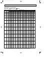
PERFORMANCE DATA COOL operation
MSH-A30WV - E1 : MUH-A30WV - E1 (230V)
CAPACITY : 8.5(KW) SHF : 0.62
INDOOR INDOOR
DB(:) WB(:) Q
21
18
9.99
21
20
10.41
22
18
9.99
22
20
10.41
22
22
10.84
23
18
9.99
23
20
10.41
23
22
10.84
24
18
9.99
24
20
10.41
24
22
10.84
24
24
11.39
25
18
9.99
25
20
10.41
25
22
10.84
25
24
11.39
26
18
9.99
26
20
10.41
26
22
10.84
26
24
11.39
26
26
11.73
27
18
9.99
27
20
10.41
27
22
10.84
27
24
11.39
27
26
11.73
28
18
9.99
28
20
10.41
28
22
10.84
28
24
11.39
28
26
11.73
29
18
9.99
29
20
10.41
29
22
10.84
29
24
11.39
29
26
11.73
30
18
9.99
30
20
10.41
30
22
10.84
30
24
11.39
30
26
11.73
31
18
9.99
31
20
10.41
31
22
10.84
31
24
11.39
31
26
11.73
32
18
9.99
32
20
10.41
32
22
10.84
32
24
11.39
32
26
11.73
NOTE
INPUT : 3260(W)
OUTDOOR DB(:)
21
25
27
30
SHC SHF INPUT Q SHC SHF INPUT Q SHC SHF INPUT Q SHC SHF INPUT
4.39 0.44 2608 9.56 4.21 0.44 2738 9.18 4.04 0.44 2869 8.84 3.89 0.44 2999
3.33 0.32 2738 9.99 3.20 0.32 2901 9.69 3.10 0.32 2967 9.35 2.99 0.32 3097
4.79 0.48 2608 9.56 4.59 0.48 2738 9.18 4.41 0.48 2869 8.84 4.24 0.48 2999
3.75 0.36 2738 9.99 3.60 0.36 2901 9.69 3.49 0.36 2967 9.35 3.37 0.36 3097
2.60 0.24 2836 10.46 2.51 0.24 3016 10.20 2.45 0.24 3097 9.78 2.35 0.24 3227
5.19 0.52 2608 9.56 4.97 0.52 2738 9.18 4.77 0.52 2869 8.84 4.60 0.52 2999
4.17 0.40 2738 9.99 4.00 0.40 2901 9.69 3.88 0.40 2967 9.35 3.74 0.40 3097
3.03 0.28 2836 10.46 2.93 0.28 3016 10.20 2.86 0.28 3097 9.78 2.74 0.28 3227
5.59 0.56 2608 9.56 5.36 0.56 2738 9.18 5.14 0.56 2869 8.84 4.95 0.56 2999
4.58 0.44 2738 9.99 4.39 0.44 2901 9.69 4.26 0.44 2967 9.35 4.11 0.44 3097
3.47 0.32 2836 10.46 3.35 0.32 3016 10.20 3.26 0.32 3097 9.78 3.13 0.32 3227
2.28 0.20 2967 10.97 2.19 0.20 3130 10.71 2.14 0.20 3227 10.37 2.07 0.20 3390
5.99 0.60 2608 9.56 5.74 0.60 2738 9.18 5.51 0.60 2869 8.84 5.30 0.60 2999
5.00 0.48 2738 9.99 4.79 0.48 2901 9.69 4.65 0.48 2967 9.35 4.49 0.48 3097
3.90 0.36 2836 10.46 3.76 0.36 3016 10.20 3.67 0.36 3097 9.78 3.52 0.36 3227
2.73 0.24 2967 10.97 2.63 0.24 3130 10.71 2.57 0.24 3227 10.37 2.49 0.24 3390
6.39 0.64 2608 9.56 6.12 0.64 2738 9.18 5.88 0.64 2869 8.84 5.66 0.64 2999
5.41 0.52 2738 9.99 5.19 0.52 2901 9.69 5.04 0.52 2967 9.35 4.86 0.52 3097
4.34 0.40 2836 10.46 4.18 0.40 3016 10.20 4.08 0.40 3097 9.78 3.91 0.40 3227
3.19 0.28 2967 10.97 3.07 0.28 3130 10.71 3.00 0.28 3227 10.37 2.90 0.28 3390
1.88 0.16 3130 11.39 1.82 0.16 3293 11.22 1.80 0.16 3390 10.88 1.74 0.16 3488
6.79 0.68 2608 9.56 6.50 0.68 2738 9.18 6.24 0.68 2869 8.84 6.01 0.68 2999
5.83 0.56 2738 9.99 5.59 0.56 2901 9.69 5.43 0.56 2967 9.35 5.24 0.56 3097
4.77 0.44 2836 10.46 4.60 0.44 3016 10.20 4.49 0.44 3097 9.78 4.30 0.44 3227
3.64 0.32 2967 10.97 3.51 0.32 3130 10.71 3.43 0.32 3227 10.37 3.32 0.32 3390
2.35 0.20 3130 11.39 2.28 0.20 3293 11.22 2.24 0.20 3390 10.88 2.18 0.20 3488
7.19 0.72 2608 9.56 6.89 0.72 2738 9.18 6.61 0.72 2869 8.84 6.36 0.72 2999
6.25 0.60 2738 9.99 5.99 0.60 2901 9.69 5.81 0.60 2967 9.35 5.61 0.60 3097
5.20 0.48 2836 10.46 5.02 0.48 3016 10.20 4.90 0.48 3097 9.78 4.69 0.48 3227
4.10 0.36 2967 10.97 3.95 0.36 3130 10.71 3.86 0.36 3227 10.37 3.73 0.36 3390
2.82 0.24 3130 11.39 2.73 0.24 3293 11.22 2.69 0.24 3390 10.88 2.61 0.24 3488
7.59 0.76 2608 9.56 7.27 0.76 2738 9.18 6.98 0.76 2869 8.84 6.72 0.76 2999
6.66 0.64 2738 9.99 6.39 0.64 2901 9.69 6.20 0.64 2967 9.35 5.98 0.64 3097
5.64 0.52 2836 10.46 5.44 0.52 3016 10.20 5.30 0.52 3097 9.78 5.08 0.52 3227
4.56 0.40 2967 10.97 4.39 0.40 3130 10.71 4.28 0.40 3227 10.37 4.15 0.40 3390
3.28 0.28 3130 11.39 3.19 0.28 3293 11.22 3.14 0.28 3390 10.88 3.05 0.28 3488
7.99 0.80 2608 9.56 7.65 0.80 2738 9.18 7.34 0.80 2869 8.84 7.07 0.80 2999
7.08 0.68 2738 9.99 6.79 0.68 2901 9.69 6.59 0.68 2967 9.35 6.36 0.68 3097
6.07 0.56 2836 10.46 5.85 0.56 3016 10.20 5.71 0.56 3097 9.78 5.47 0.56 3227
5.01 0.44 2967 10.97 4.82 0.44 3130 10.71 4.71 0.44 3227 10.37 4.56 0.44 3390
3.75 0.32 3130 11.39 3.64 0.32 3293 11.22 3.59 0.32 3390 10.88 3.48 0.32 3488
8.39 0.84 2608 9.56 8.03 0.84 2738 9.18 7.71 0.84 2869 8.84 7.43 0.84 2999
7.50 0.72 2738 9.99 7.19 0.72 2901 9.69 6.98 0.72 2967 9.35 6.73 0.72 3097
6.50 0.60 2836 10.46 6.27 0.60 3016 10.20 6.12 0.60 3097 9.78 5.87 0.60 3227
5.47 0.48 2967 10.97 5.26 0.48 3130 10.71 5.14 0.48 3227 10.37 4.98 0.48 3390
4.22 0.36 3130 11.39 4.10 0.36 3293 11.22 4.04 0.36 3390 10.88 3.92 0.36 3488
8.79 0.88 2608 9.56 8.42 0.88 2738 9.18 8.08 0.88 2869 8.84 7.78 0.88 2999
7.91 0.76 2738 9.99 7.59 0.76 2901 9.69 7.36 0.76 2967 9.35 7.11 0.76 3097
6.94 0.64 2836 10.46 6.69 0.64 3016 10.20 6.53 0.64 3097 9.78 6.26 0.64 3227
5.92 0.52 2967 10.97 5.70 0.52 3130 10.71 5.57 0.52 3227 10.37 5.39 0.52 3390
4.69 0.40 3130 11.39 4.56 0.40 3293 11.22 4.49 0.40 3390 10.88 4.35 0.40 3488
Q : Total capacity (kW)
SHC : Sensible heat capacity (kW)
SHF : Sensible heat factor
INPUT : Total power input (W)
22
DB : Dry-bulb temperature
WB : Wet-bulb temperature
OB322-1.qxp
03.11.13 4:06 PM
Page 23
PERFORMANCE DATA COOL operation
MSH-A30WV - E1 : MUH-A30WV - E1 (230V)
CAPACITY : 8.5(KW) SHF : 0.62
INDOOR INDOOR
DB(:) WB(:) Q
21
18
8.33
21
20
8.76
22
18
8.33
22
20
8.76
22
22
9.27
23
18
8.33
23
20
8.76
23
22
9.27
24
18
8.33
24
20
8.76
24
22
9.27
24
24
9.78
25
18
8.33
25
20
8.76
25
22
9.27
25
24
9.78
26
18
8.33
26
20
8.76
26
22
9.27
26
24
9.78
26
26
10.29
27
18
8.33
27
20
8.76
27
22
9.27
27
24
9.78
27
26
10.29
28
18
8.33
28
20
8.76
28
22
9.27
28
24
9.78
28
26
10.29
29
18
8.33
29
20
8.76
29
22
9.27
29
24
9.78
29
26
10.29
30
18
8.33
30
20
8.76
30
22
9.27
30
24
9.78
30
26
10.29
31
18
8.33
31
20
8.76
31
22
9.27
31
24
9.78
31
26
10.29
32
18
8.33
32
20
8.76
32
22
9.27
32
24
9.78
32
26
10.29
NOTE
INPUT : 3260(W)
OUTDOOR DB(:)
35
40
SHC SHF INPUT Q SHC SHF INPUT
3.67 0.44 3195 7.65 3.37 0.44 3390
2.80 0.32 3325 8.16 2.61 0.32 3488
4.00 0.48 3195 7.65 3.67 0.48 3390
3.15 0.36 3325 8.16 2.94 0.36 3488
2.22 0.24 3456 8.67 2.08 0.24 3651
4.33 0.52 3195 7.65 3.98 0.52 3390
3.50 0.40 3325 8.16 3.26 0.40 3488
2.59 0.28 3456 8.67 2.43 0.28 3651
4.66 0.56 3195 7.65 4.28 0.56 3390
3.85 0.44 3325 8.16 3.59 0.44 3488
2.96 0.32 3456 8.67 2.77 0.32 3651
1.96 0.20 3586 9.18 1.84 0.20 3749
5.00 0.60 3195 7.65 4.59 0.60 3390
4.20 0.48 3325 8.16 3.92 0.48 3488
3.34 0.36 3456 8.67 3.12 0.36 3651
2.35 0.24 3586 9.18 2.20 0.24 3749
5.33 0.64 3195 7.65 4.90 0.64 3390
4.55 0.52 3325 8.16 4.24 0.52 3488
3.71 0.40 3456 8.67 3.47 0.40 3651
2.74 0.28 3586 9.18 2.57 0.28 3749
1.65 0.16 3716 9.69 1.55 0.16 3879
5.66 0.68 3195 7.65 5.20 0.68 3390
4.90 0.56 3325 8.16 4.57 0.56 3488
4.08 0.44 3456 8.67 3.81 0.44 3651
3.13 0.32 3586 9.18 2.94 0.32 3749
2.06 0.20 3716 9.69 1.94 0.20 3879
6.00 0.72 3195 7.65 5.51 0.72 3390
5.25 0.60 3325 8.16 4.90 0.60 3488
4.45 0.48 3456 8.67 4.16 0.48 3651
3.52 0.36 3586 9.18 3.30 0.36 3749
2.47 0.24 3716 9.69 2.33 0.24 3879
6.33 0.76 3195 7.65 5.81 0.76 3390
5.60 0.64 3325 8.16 5.22 0.64 3488
4.82 0.52 3456 8.67 4.51 0.52 3651
3.91 0.40 3586 9.18 3.67 0.40 3749
2.88 0.28 3716 9.69 2.71 0.28 3879
6.66 0.80 3195 7.65 6.12 0.80 3390
5.95 0.68 3325 8.16 5.55 0.68 3488
5.19 0.56 3456 8.67 4.86 0.56 3651
4.30 0.44 3586 9.18 4.04 0.44 3749
3.29 0.32 3716 9.69 3.10 0.32 3879
7.00 0.84 3195 7.65 6.43 0.84 3390
6.30 0.72 3325 8.16 5.88 0.72 3488
5.56 0.60 3456 8.67 5.20 0.60 3651
4.69 0.48 3586 9.18 4.41 0.48 3749
3.70 0.36 3716 9.69 3.49 0.36 3879
7.33 0.88 3195 7.65 6.73 0.88 3390
6.65 0.76 3325 8.16 6.20 0.76 3488
5.93 0.64 3456 8.67 5.55 0.64 3651
5.08 0.52 3586 9.18 4.77 0.52 3749
4.11 0.40 3716 9.69 3.88 0.40 3879
Q : Total capacity (kW)
SHC : Sensible heat capacity (kW)
Q
7.35
7.86
7.35
7.86
8.37
7.35
7.86
8.37
7.35
7.86
8.37
8.93
7.35
7.86
8.37
8.93
7.35
7.86
8.37
8.93
9.39
7.35
7.86
8.37
8.93
9.39
7.35
7.86
8.37
8.93
9.39
7.35
7.86
8.37
8.93
9.39
7.35
7.86
8.37
8.93
9.39
7.35
7.86
8.37
8.93
9.39
7.35
7.86
8.37
8.93
9.39
SHF : Sensible heat factor
INPUT : Total power input (W)
23
SHC
3.24
2.52
3.53
2.83
2.01
3.82
3.15
2.34
4.12
3.46
2.68
1.79
4.41
3.77
3.01
2.14
4.71
4.09
3.35
2.50
1.50
5.00
4.40
3.68
2.86
1.88
5.29
4.72
4.02
3.21
2.25
5.59
5.03
4.35
3.57
2.63
5.88
5.35
4.69
3.93
3.01
6.18
5.66
5.02
4.28
3.38
6.47
5.98
5.36
4.64
3.76
43
SHF INPUT
0.44 3456
0.32 3586
0.48 3456
0.36 3586
0.24 3716
0.52 3456
0.40 3586
0.28 3716
0.56 3456
0.44 3586
0.32 3716
0.20 3831
0.60 3456
0.48 3586
0.36 3716
0.24 3831
0.64 3456
0.52 3586
0.40 3716
0.28 3831
0.16 3961
0.68 3456
0.56 3586
0.44 3716
0.32 3831
0.20 3961
0.72 3456
0.60 3586
0.48 3716
0.36 3831
0.24 3961
0.76 3456
0.64 3586
0.52 3716
0.40 3831
0.28 3961
0.80 3456
0.68 3586
0.56 3716
0.44 3831
0.32 3961
0.84 3456
0.72 3586
0.60 3716
0.48 3831
0.36 3961
0.88 3456
0.76 3586
0.64 3716
0.52 3831
0.40 3961
DB : Dry-bulb temperature
WB : Wet-bulb temperature
OB322-1.qxp
03.11.13 4:06 PM
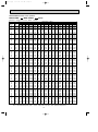
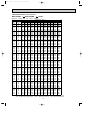
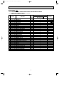
Page 24
PERFORMANCE DATA HEAT operation
MSH-A18WV - E1 : MUH-A18WV - E1 (230V)
CAPACITY : 5.2(KW) INPUT : 1610(W)
OUTDOOR WB(:)
-10
-5
0
5
10
15
20
INDOOR
DB(:)
Q INPUT Q INPUT Q INPUT Q INPUT Q INPUT Q INPUT Q INPUT
3.28 1047 3.95 1256 4.63 1417 5.30 1530 5.98 1626 6.60 1674 7.28 1707
15
3.12 1127 3.74 1336 4.42 1481 5.04 1594 5.72 1674 6.34 1723 6.99 1787
21
2.81 1208 3.48 1417 4.11 1562 4.78 1674 5.46 1755 6.08 1803 6.76 1852
26
NOTE
Q :Total capacity (kW)
INPUT:Total power input (W)
DB : Dry-bulb temperature
MSH-A24WV - E1 : MUH-A24WV - E1 (230V)
CAPACITY : 7.2(KW) INPUT : 2480(W)
OUTDOOR WB(:)
-10
-5
0
5
10
15
20
INDOOR
DB(:)
Q INPUT Q INPUT Q INPUT Q INPUT Q INPUT Q INPUT Q INPUT
4.54 1612 5.47 1934 6.41 2182 7.34 2356 8.28 2505 9.14 2579 10.08 2629
15
4.32 1736 5.18 2058 6.12 2282 6.98 2455 7.92 2579 8.78 2654 9.68 2753
21
3.89 1860 4.82 2182 5.69 2406 6.62 2579 7.56 2703 8.42 2778 9.36 2852
26
NOTE
Q :Total capacity (kW)
INPUT:Total power input (W)
DB : Dry-bulb temperature
MSH-A30WV - E1 : MUH-A30WV - E1 (230V)
CAPACITY : 9.4(KW) INPUT : 3430(W)
OUTDOOR WB(:)
-10
-5
0
5
10
15
20
INDOOR
DB(:)
Q INPUT Q INPUT Q INPUT Q INPUT Q INPUT Q INPUT Q INPUT
5.92 2230 7.14 2675 8.37 3018 9.59 3259 10.81 3464 11.94 3567 13.16 3636
15
5.64 2401 6.77 2847 7.99 3156 9.12 3396 10.34 3567 11.47 3670 12.64 3807
21
5.08 2573 6.30 3018 7.43 3327 8.65 3567 9.87 3739 11.00 3842 12.22 3945
26
NOTE
Q :Total capacity (kW)
INPUT:Total power input (W)
24
DB : Dry-bulb temperature
OB322-1.qxp
03.11.13 4:06 PM
9
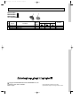
Page 25
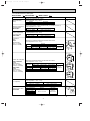
MICROPROCESSOR CONTROL
MUH-A18WV - E1
MUH-A24WV - E1
MUH-A30WV - E1
9-1. “I FEEL CONTROL” ( ) OPERATION
9-1-1. COOL mode of “I FEEL CONTROL”
1. Outdoor fan speed control <MUH-A30WV>
Outdoor fan speed is controlled according to the temperature of ambient temperature thermistor RT63.
Outdoor fan Low operation : When the outside temperature decreases to 20°C or less.
Until the outside temperature goes to 22°C.
Outdoor fan High operation : Until the outside temperature decreases to 20°C or less.
When the outside temperature goes to 22°C.
Ambient temperature
Outdoor fan speed
thermistor RT63 temperature
High
Low
20: 22:
NOTE1. : If the temperature of RT63 reads from 20: to 22: at the air conditioner starting outdoor fan speed is High.
NOTE2. : When indoor fan speed is Low except HEAT operation mode and the outside temperature is 30: or less, the
outdoor fan operates at Low.
Outdoor fan Low operation is cancelled according to the following conditions(1 or 2):
1 When the operation is not changed and the outside temperature goes to 33: or more.
2 When the operation is changed. (Change to HEAT operation mode / Change of the indoor fan speed)
2. Discharge temperature protection <MUH-A30WV>
The compressor is controlled by the temperature of discharge temperature thermistor RT62 for excess rise protection of
compressor discharge pressure.
• Compressor
When the temperature of discharge temperature thermistor RT62 goes to 120: or more, the compressor is turned OFF.
After 3 minutes since the compressor has been turned OFF, if the temperature of discharge temperature thermistor RT62
becomes 100: or less, the compressor is turned ON.
9-1-2. DRY mode of “I FEEL CONTROL”
1. Outdoor fan speed control <MUH-A30WV>
Outdoor fan speed control is as same as one of COOL mode of “I FEEL CONTROL”.
9-1-3. HEAT mode of “I FEEL CONTROL”
1. Outdoor fan speed control <MUH-A30WV>
Outdoor fan speed is controlled according to the temperature of ambient temperature thermistor RT63.
Outdoor fan Low operation : Until the outside temperature decreases to 13°C.
When the outside temperature goes to 18°C or more.
Outdoor fan High operation :When the outside temperature decreases to 13°C or less.
Until the outside temperature goes to 18°C.
Ambient temperature
Outdoor fan speed
thermistor RT63 temperature
High
Low
2. High pressure protection
13: 18:
<MUH-A18/A24WV>
During heating operation, the outdoor fan motor is controlled by the temperature of indoor coil thermistor RT12 for excess
rise protection of compressor discharge pressure.
(MUH-A18WV)Outdoor fan OFF : 52°C
Outdoor fan ON : 48°C
Outdoor fan
(MUH-A24WV)Outdoor fan OFF : 58°C
High pressure protection
OFF
Outdoor fan ON : 55°C
Released
(MUH-A18WV)
(MUH-A24WV)
High pressure protection chart
Example
Indoor coil thermistor
RT12 temperature
(MUH-A18WV) 52˚C
(MUH-A24WV) 58˚C
ON
48:
55:
52:
58:
Outdoor fan motor
turn OFF
Outdoor fan motor
turn ON
(MUH-A18WV) 48˚C
(MUH-A24WV) 55˚C
ON
ON
Outdoor fan motor
OFF
OFF
25
OB322-1.qxp
03.11.13 4:06 PM
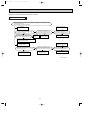
Page 26
NOTE : During high pressure protection and for 4 minutes and 15 seconds after high pressure protection, defrosting of
outdoor heat exchanger is not detected by the defrost thermistor RT61.
<MUH-A30WV>
During heating operation, the outdoor fan and the compressor are controlled by the temperature of indoor coil thermistor
RT12 for excess rise protection of compressor discharge pressure.
• Outdoor fan
When the temperature of indoor coil thermistor RT12 goes to 55: or more, the outdoor fan is turned OFF.
When the temperature of indoor coil thermistor RT12 becomes to 52: or less, the outdoor fan is turned ON.
• Compressor
When the temperature of indoor coil thermistor RT12 goes to 75: or more, the compressor is turned OFF.
3 minutes after the compressor is turned OFF and if the temperature of indoor coil thermistor RT12 becomes 75: or less,
the compressor is turned ON.
NOTE : During the high pressure protection and for 10 seconds after high pressure protection, defrosting of outdoor heat
exchanger is not detected by the defrost thermistor RT61.
3. Discharge temperature protection <MUH-A30WV>
Discharge temperature protection is as same as during COOL mode of “I FEEL CONTROL”.
4. Defrosting
Defrosting of outdoor heat exchanger is controlled by deicer P.C. board, with detection by the defrost thermistor RT61.
(1) Starting conditions of defrost
When all conditions of a) ~ c) are satisfied, the defrosting operation starts.
a) Under the heat operation, the compressor cumulative operation time exceeds 40 minutes without the defrosting operation working.
b) The defrost thermistor RT61 reads -3°C or less.
c) After releasing the high pressure protection 4 minutes and 15 seconds(MUH-18/24WV)/ 10 seconds(MUH-30WV) have
elapsed.
(2) Releasing conditions of defrost
When the condition d) or e) is satisfied, the defrosting operation stops.
d) The defrost thermistor RT61 reads 3°C(MUH-18/24WV)/ 13°C(MUH-30WV) or more.
e) The defrosting time exceeds 10 minutes.
(3) Defrosting time chart
Defrost thermistor RT61
13: or more(MUH-A30WV)
3: or more(MUH-A18/A24WV)
-3: or less
Outdoor 52C
contactor(Compressor)
ON
OFF
X62
(R.V. coil)
OFF
SR61
Outdoor fan
ON
Defrost
counter
ON
Indoor fan
Indoor vane
15 sec.
ON
30 sec.
30 sec.
5 sec.
OFF
OFF
ON
Very Low
OFF
Max 10 min.
NOTE
Horizontal
Set position
NOTE: • When the indoor coil thermistor RT12 reads above 18°C, indoor fan operates at Very Low for 30 seconds.
• When the indoor coil thermistor RT12 reads 18°C or less, the indoor fan stops.
26
03.11.13 4:06 PM
Page 27
5. R.V. coil control
Heating · · · · · ON
Cooling · · · · · OFF
Dry · · · · · · · · OFF
NOTE: The 4-way valve reverses for 5 seconds right before start-up of the compressor.
Compressor
R.V. coil
ON
OFF
ON
OFF
Outdoor fan
ON
OFF
(COOL / DRY)
(HEAT)
5 sec.
5 sec.
ON
OFF
ON
OFF
ON
OFF
9-2. LEV control <MUH-A30WV>
Basic specification
LEV (Expansion valve) is controlled by “Thermostat ON” commands given from the unit.
General operation
OB322-1.qxp
Controlled range
Minimum : 54 pulse, Maximum : 500 pulse
Drive speed
30 ~ 90 pulse / second
Opening set
The setting is always in opening direction.
(To close the LEV, it is closed to the pulse smaller than the one which is
set finally. Then the LEV is opened to the final setting pulse.)
Stop of indoor unit
Opening in stop : 150 pulse ➔ LEV opening is set to becomes 500 pulse
after 3 minutes passed.
Remote controller ON
LEV positioning (LEV is closed completely at once)
Power ON (Breaker ON)
LEV is positioned. However, afterwards, LEV is not positioned at the first
remote controller ON.
Approximate for 2 minutes since
compressor has started.
Opening is set by the initial opening.
(Initial opening is set according to each operation modes and
outer temperature conditions.)
From approximate 2 minutes to
approximate 13 minutes
(for 11 minutes) since compressor
has started.
Opening is set by standard opening.
(Standard opening is set according to each operation modes and
outer temperature conditions.)
After 13 minutes passed since
compressor has started.
LEV opening is corrected to be once every 2 minutes so that discharge
temperature becomes the target discharge temperature.
(When the discharge temperature is lower than target one : LEV is corrected in
closed direction, when the discharge temperature is higher than target one :
LEV is corrected in opening direction.)
At thermostat OFF
Opening in stop : 150 pulse ➔ LEV is set to the initial opening after about
3 minutes passed.
At thermostat ON
Same as the starting of compressor operation
At remote controller OFF
Opening in stop : 150 pulse ➔ LEV is set so that the opening is opened
completely at the speed of 4 pulse every 5 seconds in opening after about
3 minutes passed.
27
OB322-1.qxp
03.11.13 4:06 PM
Page 28
(1) LEV opening correction by discharge temperature
The LEV opening is corrected according to the temperature difference between target discharge temperature (Tb) and
actual discharge temperature (Ta).
1 The LEV correction is used properly for two kinds according to the LEV opening status at operation off.
Opening immediately before having stopped last time
Rank
100 pulse or less
100 pulse or more
Cooling / Heating
Cooling / Heating
more than Tb+10
5
20
Tb+5 to Tb+10
2
10
Tb+2 to Tb+5
1
2
Tb-2 to Tb+2
0
0
Tb-5 to Tb-2
-1
-2
Tb-10 to Tb-5
-2
-5
less than Tb-10
-5
-10
Ta (:)
NOTE : Discharge temperature : Ta, Target discharge temperature : Tb
2 When the temperature difference
RT between indoor coil thermistor (main) RT12 and indoor coil thermistor (sub)
RT13 in the indoor unit is 2: or more for a fixed time at cool or dry operation, the target discharge temperature is
changed. After the temperature is changed, when temperature difference
RT is 3: or more, the target temperature
is changed again. The LEV opening is controlled based on the changed target discharge temperature and the temperature difference
RT.
RT
Ta (:)
less than 2:
2: or more and less than 3:
3: or more
more than Tb+10
20
60
60
Tb+5 to Tb+10
10
20
20
Tb+2 to Tb+5
2
2
2
Tb-2 to Tb+2
0
0
0
Tb-5 to Tb-2
-2
-2
-2
Tb-10 to Tb-5
-5
-5
-5
less than Tb-10
-10
-10
-10
NOTE : Discharge temperature : Ta, Target discharge temperature : Tb
The target discharge temperature (Tb) is set according to the operation mode or the unit status as follows.
Tb (:)
Operation mode
HEAT
85
COOL (Normal)
80
COOL (
RT is less than 2:, or
COOL (
RT is 3 :or more.)
RT is 2:or more and less than 3:.)
70
65
NOTE : Target discharge temperature : Tb
NOTE : When the discharge temperature (Ta) is 50: or less on the cool operation, or is 49: or less on heat operation,
LEV opening is set in 54 pulse.
When this state continues for 20 minutes, the compressor is stopped and restarts in 3 minutes.
When the compressor is stopped, the indoor unit indicates the abnormality of refrigerant system and stops.
(OPERATION INDICATOR lamp is 10-time flashing on and off.)
28
03.11.13 4:06 PM
Page 29
(2) LEV time chart
Open
LEV opening
OB322-1.qxp
Opening
Power ON completely
Operation
Remote
➔ controller
ON
Standard opening
Thermostat
OFF
Initial opening
Remote Opening ➔ Remote
controller completely controller
ON
Operation OFF
Standard opening
Thermostat
ON
Initial opening
Opening in stop
Positioning
Operation
Standard opening
Initial opening
Opening in stop
Positioning
Close
NOTE : Opening increases and decreases to be in the target discharge temperature during operation.
10
Time
SERVICE FUNCTIONS
MUH-A18WV - E1 MUH-A24WV - E1 MUH-A30WV - E1
10-1. COMPULSORY DEFROSTING MODE FOR SERVICE
By short circuit of the connector JPDS and JPSG(MUH-A18WV)/ JPG1 and R871(MUH-A24/A30WV) on the outdoor deicer
P.C. board, defrosting mode can be accomplished regardless of the defrost interval restriction. (Refer to page 37 or 38.)
Defrost thermistor RT61 must read below -3°C.
10-2. CHANGE IN DEFROST SETTING
<JRF> When the JRF wire of the deicer P.C. board is cut, the defrost interval time will be changed.
<JRG> When the JRG wire of the deicer P.C. board is cut, the defrost temperature will be changed.
(Refer to page 37 or 38.)
Jumper wire
Model
MUH-A18WV -
E1
MUH-A24WV -
E1
MUH-A30WV -
E1
11
Change point
JRF
Defrost interval time changes from 40 minutes to 15 minutes.
JRG
Defrost start temperature changes from -3: to 0:. (MUH-A18WV)
Defrost start temperature does not change.(-3.0:)(MUH-A24/A30WV)
Defrost finish temperature changes from 3: to 10:.(MUH-A18WV)
Defrost finish temperature changes from 3: to 15:.(MUH-A24WV)
Defrost finish temperature changes from 13: to 15:.(MUH-A30WV)
TROUBLESHOOTING
MUH-A18WV - E1 MUH-A24WV - E1 MUH-A30WV - E1
11-1. Cautions on troubleshooting
1. Before troubleshooting, check the following:
(1) Check the power supply voltage.
(2) Check the indoor/outdoor connecting wire for mis-wiring.
2. Take care the following during servicing.
(1) Before servicing the air conditioner, be sure to first turn off the remote controller to stop the main unit, and then after
confirming the horizontal vane is closed, turn off the breaker and / or disconnect the power plug.
(2) Be sure to turn OFF the power supply before removing the front panel, the
cabinet, the top panel, and the electronic control P.C. board.
(3) When removing the electronic control P.C. board, hold the edge of the
board with care NOT to apply stress on the components.
(4) When connecting or disconnecting the connectors, hold the housing of the
connector. DO NOT pull the lead wires.
Housing point
Lead wiring
3. Troubleshooting procedure
(1) First, check if the OPERATION INDICATOR lamp on the indoor unit is flashing on and off to indicate an abnormality.
To make sure, check how many times the abnormality indication is flashing on and off before starting service work.
(2) Before servicing check that the connector and terminal are connected properly.
(3) If the electronic control P.C. board is supposed to be defective, check the copper foil pattern for disconnection and the
components for bursting and discolouration.
(4) When troubleshooting, refer to the flow chart on page 30.
29
OB322-1.qxp
03.11.13 4:06 PM
Page 30
Start
Indoor unit
operates.
Outdoor unit
doesn't
operate.
Outdoor unit
operates in
only Test Run
operation.
Check room
temperature
thermistor.
Refer to
"Test point
diagram and
voltage".
Outdoor unit
doesn't
operate
even in
Test Run
operation.
Refer to A
"Check of
outdoor unit"
on page 32 or
33.
Indoor unit
operates.
Outdoor unit
doesn't operate
normally.
Outdoor unit
doesn't
stop even
if indoor unit
stops.
Refer to B
"Check of
outdoor unit"
on page 34.
Flash on and
off at 0.5second
intervals
Cause:
Indoor/
Outdoor unit
• Mis-wiring
2-time flash
Cause:
Indoor unit
• Trouble of
room temperature/
indoor coil
thermistor
3-time flash
Cause:
Indoor unit
• Trouble of
indoor fan
motor
Refer to D
"How to
check
mis-wiring
(When
outdoor unit
doesn't
work)" on
page 35.
Check room
temperature
thermistor
and indoor
coil thermistor.
Refer to
"Test point
diagram and
voltage".
Refer to
"Check of
indoor fan
motor".
Indoor unit
doesn't receive
the signal from
remote controller.
OPERATION INDICATOR
lamp on the indoor unit is
flashing on and off.
Unit doesn't
operate
normal
operation in
COOL or
HEAT mode.
Indoor unit
operates, when
the EMERGENCY
OPERATION
switch is pressed.
Indoor unit
doesn't operate,
when the
EMERGENCY
OPERATION
switch is pressed.
Refer to C
"Check of
R.V. coil"
on page 34
or 35.
Refer to
"Check of
remote controller
and receiver
P.C. board".
1. Check indoor /
outdoor
connecting wire.
2. Refer to
"Check of indoor
electronic control
P.C. board".
4-time flash
Cause:
Indoor unit
• Trouble of
indoor unit
control
system
7-time flash
6-time flash
Cause:
Cause:
Outdoor unit
Outdoor unit
• Trouble of
• Trouble of
outdoor
thermistor
control
in outdoor
system
unit
Replace the
indoor
electronic
control
P.C. board.
Refer to F
"Check of
outdoor
thermistor"
on page 36.
As for indoor unit, refer to service manual OB321.
30
Replace the
deicer
P.C. board.
10-time flash
Cause:
Outdoor unit
MUH-A30WV
• Trouble of
low discharge
temperature
protection
MUH-A30WV
Refer to E
"Check of
LEV" on
page 36.
03.11.13 4:08 PM
Page 31
11-2. Trouble criterion of main parts
MUH-A18WV - E1
Part name
Defrost thermistor
(RT61)
Discharge temperature
thermistor(RT62)
MUH-A30WV
MUH-A24WV - E1
MUH-A30WV - E1
Check method and criterion
Measure the resistance with a tester.
(Part temperature –10˚C ~ 40˚C)
Normal
5 k" ~ 60 k"
Figure
Abnormal
Open or short-circuit
Measure the resistance with a tester.
Before measurement, hold the thermistor with your hands to warm it up.
(Part temperature 0˚C ~ 40˚C)
Normal
120 k" ~ 800k"
Abnormal
Open or short-circuit
Ambient temperature
thermistor(RT63)
MUH-A30WV
Measure the resistance with a tester.
(Part temperature –10˚C ~ 40˚C)
Abnormal
Normal
Open or short-circuit
5 k" ~ 60 k"
Compressor
(MC)
INNER
PROTECTOR
160i 5: OPEN
90i10: CLOSE
Measure the resistance between the terminals with a tester.
(Part temperature –10˚C ~ 40˚C)
Normal
Terminal
MUH-A18WV MUH-A24WV
MUH-A30WV
C – R 1.59 " ~ 1.95 " 0.71 " ~ 0.87 " 0.56 " ~ 0.71 "
C – S 2.65 " ~ 3.24 " 1.45 " ~ 1.77 " 1.43 " ~ 1.76 "
WHT C
P
AUX
Abnormal
~
MAIN
R
BLK
S
Open or
short-circuit
RED
MUH-A18WV
MAIN
AUX
P
Outdoor fan motor(MF)
MUH-A18/A24WV
INNER
PROTECTOR
145i 8: OPEN
( 88i15: CLOSEw)
MUH-A30WV
INNER
PROTECTOR
135i 5: OPEN
( 83i15: CLOSEw)
Measure the resistance between the terminals with a tester.
(Part temperature –10˚C ~ 40˚C)
Color of
lead wire MUH-A18WV
WHT – BLK 102 " ~ 126 "
BLK – RED 97 " ~ 120 "
–
BLK – YLW
–
YLW – RED
Normal
Abnormal
MUH-A24WV MUH-A30WV
55 " ~ 68 " 55.4 " ~ 67.7 "
Open or
–
–
short-circuit
26 " ~ 33 " 49.3 " ~ 60.3 "
55 " ~ 68 " 22.9 " ~ 28.0 "
BLK RED ORN WHT
MUH-A24WV
MAIN
AUX.1 AUX.2
P
C
BLK YLW RED ORN WHT
MUH-A30WV
MAIN
AUX.1 AUX.2
P
C
BLK YLW RED ORN WHT
Measure the resistance between the terminals with a tester.
(Part temperature –10˚C ~ 40˚C)
Measure the resistance with a tester.
(Part temperature : –10˚C ~ 40˚C)
Normal
Color of lead wire
WHT – RED
RED – ORN
30.3 " ~ 37.0 "
YLW – BRN
BRN – BLU
w Reference value
WHT6
Abnormal
Open or
short-circuit
RED1
LEV
ORN4
BLU3
LEV(Expansion valve)
MUH-A30WV
Abnormal
Open or short-circuit
Normal
2.673 k" ~ 3.268 k"
YLW5
R.V. coil(21S4)
BRN2
OB322-2.qxp
P :INNER PROTECTOR
31
OB322-2.qxp
03.11.13 4:08 PM
Page 32
Compressor and/or outdoor fan motor doesn’t operate.
A Check of outdoor unit
MUH-A18WV
Operate the unit in COOL or HEAT mode by pressing the EMERGENCY OPERATION switch.
3-minute time delay works.
Test run operation operates for 30 minutes.
Compressor
doesn't operate.
Rectify the indoor and
outdoor connecting wire.
No
Is there 230V AC between 4 on the
Is there 5V DC between J205 + –J101 – on
compressor contactor (52C) and
the deicer P.C. board? w
TAB20 on the deicer P.C. board? w
Yes
Yes
Is there 230V AC between 3 on the
No Replace the
Replace the
compressor contactor (52C) and N
deicer P.C.
deicer P.C. board.
on the outdoor terminal block (TB1)?
board.
Yes
No
No
Is there 230V AC between L–N on
the outdoor terminal block (TB1)?
Yes
Rectify the connecting wire.
Check the compressor and compressor
capacitor. Refer to page 31.
Rectify the indoor and
outdoor connecting wire.
Outdoor fan motor
doesn't operate.
No
Is there 5V DC between J205 + –J101 – on
the deicer P.C. board? w
Yes
Check the outdoor fan motor.
Refer to page 31.
No
Is there 230V AC between 4 on the
compressor contactor (52C) and
TAB 20 on the deicer P.C. board? w
Yes
Replace the
deicer P.C. board.
No
Is there 230V AC between L–N on
the outdoor terminal block (TB1)?
Yes
Rectify the connecting wire.
w Refer to page 37.
32
OB322-2.qxp
03.11.13 4:08 PM
Page 33
MUH-A24WV
MUH-A30WV
Turn ON the power supply.
Is there 230V AC to
between L-N on the
outdoor terminal block?
No
Check the outdoor power supply
and connection of wiring.
Yes
Compressor
does not operate.
Is there 5V DC between
No
J101 + - J401 on the deicer
P.C. board? w
Yes
Operate the unit in
COOL or HEAT mode by
pressing the EMERGENCY
OPERATION switch.
3minutes after the power
supply turns ON, is there
230V AC between A1-A2 on
the compressor contactor
(52C)?
Yes
Is there 230V AC between
CN730 1-3 on the deicer
P.C. board? w
Yes
No
Rectify the connecting
wire.
Replace the
deicer P.C. board.
No
Is there 230V AC between
No
2/T1 on the compressor
contactor(52C) and N on the
outdoor terminal block?
Replace the
deicer P.C. board.
Is there 230V AC between
No
1/L1 on the compressor
contactor(52C) and N on the
outdoor terminal block?
Yes
Rectify the connecting
wire.
Yes
Check the compressor.
Refer to page 31.
Replace the compressor
contactor(52C).
Outdoor fan motor
does not operate.
Is there 5V DC between
No
J101 + - J401 on the deicer
P.C. board? w
Is there 230V AC CN730
1-3 on the deicer P.C.
board? w
Yes
Rectify the connecting
wire.
Yes
Operate the unit in
COOL or HEAT mode by
pressing the EMERGENCY
OPERATION switch.
Is there 230V AC between
CN711 2-3 (MUH-A24WV)/
CN711 1-3 or 2-3
(MUH-A30WV) on the
deicer P.C. board? w
No
Replace the
deicer P.C. board.
No
Replace the
deicer P.C. board.
Yes
w Refer to page 38.
Check the outdoor fan
motor. Refer to page 31.
33
OB322-2.qxp
03.11.13 4:08 PM
Page 34
Compressor and/or outdoor fan motor doesn’t stop.
B Check of outdoor unit
MUH-A18WV
Turn OFF the power supply.
After 1 minute, turn ON
power supply again.
No
Does compressor stop?
Yes
Is there 230V AC between 3 on the
compressor contactor (52C) and N on the
outdoor terminal block (TB1)?
Yes
OK
No
Rectify the connecting wire.
Replace the
deicer P.C. board.
No
Replace the
deicer P.C. board.
Does outdoor fan motor stop?
Yes
OK
MUH-A24WV
MUH-A30WV
1 Turn OFF the power supply.
2 After 30 seconds, turn ON the power supply again.
3 Operate the unit in COOL or HEAT mode by
pressing the EMERGENCY OPERATION switch.
4 Operate the unit for 1 minute or more and stop it by
pressing the EMERGENCY OPERATION switch again.
After 30 seconds,
does compressor stop?
No
Yes
Is there 230V AC between
A1-A2 on the compressor
contactor (52C)?
Yes
No
Is there 230V AC between
No
2/T1 on the compressor
contactor (52C) and N on the
outdoor terminal block?
Yes
Ok
Replace the
deicer P.C. board.
After 30 seconds, does
outdoor fan motor stop?
No
Replace the
compressor contactor(52C).
Replace the
deicer P.C. board.
Yes
Ok
Unit operates COOL mode even if it is set to HEAT mode.
C Check of R.V. coil
w First, measure the resistance of R.V. coil to confirm it is disconnected or is not short-circuit.
Disconnect the TAB52 on the deicer P.C. board.
Turn ON the power supply and operate
the indoor unit in HEAT mode by pressing
the EMERGENCY OPERATION switch.
After 3 minutes, is there
230V AC between CN721
1-3 on the deicer P.C. board?
Yes
No
Replace the
deicer P.C. board.
Replace the R.V. coil.
34
Rectify the connecting
wire.
OB322-2.qxp
03.11.13 4:08 PM
Page 35
Unit operates HEAT mode even if it is set to COOL mode.
C Check of R.V. coil
w First, measure the resistance of R.V. coil to confirm it is disconnected or is not short-circuit.
Disconnect the TAB52 on the deicer P.C. board.
Turn ON the power supply and operate
the indoor unit in COOL mode by pressing
the EMERGENCY OPERATION switch.
After 3 minutes, is there
230V AC between CN721
1-3 on the deicer P.C. board?
Yes
No
Replace the R.V. coil.
Replace the
deicer P.C. board.
When OPERATION INDICATOR lamp flashes ON and OFF in every 0.5-second.
Outdoor unit doesn’t operate.
D How to check mis-wiring
w Short circuit of JPG and JPS on the indoor electronic control
P.C. board enables self -check to be displayed in 3 seconds.
Start
• Turn ON the power supply. (indoor/ outdoor unit)
• Press once EMERGENCY OPERATION switch.
After 3 minutes, mis-wiring is indicated
(0.5-second ON, 0.5-second OFF)
on OPERATION INDICATOR
lamp on indoor unit.w
Yes
Make them sure.
Is this mis-wiring, poor contact,
or wire disconnection?
No
1. Turn OFF the power supply (indoor/ outdoor unit) and disconnect indoor/outdoor
connecting wire on indoor side.
2. Short-circuit terminal block N-3 by lead wire.
3. Turn ON the power supply (indoor unit) and press once EMERGENCY OPERATION switch.
Is there 20V DC between both ends of
R132 on the indoor electronic control P.C.
board ?
( By tester, the stylus is between 0 ~ 20V. )
No
Replace the indoor electronic
control P.C. board.
Yes
• Turn OFF the power supply. (indoor unit)
• Connect ON indoor/outdoor connecting
wire.
Turn ON the power supply. (outdoor unit)
No
Is there 230V AC between L-N
on the outdoor terminal block?
Check the outdoor power supply
and connection of wiring.
Yes
Is there 5V DC between J205 + -J101 (MUH-A18WV)/J101 + -J401 - (MUH-A24/A30
WV) on the deicer P.C. board?(Refer to page
37 or 38.)
Yes
During EMERGENCY OPERATION, is there
10V DC between both ends of R601on the
deicer P.C. board? (Refer to page 37or 38.)
(By tester, the stylus is between 5 ~10V)
No
Yes
No
Replace the deicer P.C. board.
35
Replace the deicer P.C. board.
Make the wiring between CN730
on the deicer P.C. board and
outdoor terminal block correct.
(Refer to page 37 or 38.)
As for indoor unit,
refer to service
manual OB321.
OB322-2.qxp
03.11.13 4:08 PM
Page 36
When OPERATION INDICATOR lamp flashes 10-time.
Heating/ Cooling doesn't operate.
E Check of LEV (Expansion valve)
MUH-A30WV
1 During pressing OPERATION SELECT button
on remote controller, press RESET button.
2 First, release RESET button.
1 During pressing OPERATION SELECT
(Confirm all displays of remote controller.)
button on remote controller, press
3 Then release OPERATION SELECT button.
RESET button.
2 First, release RESET button.
With remote controller set toward the indoor unit, press
OPERATE/ STOP(ON/ OFF) button and confirm one
beep tone.
(Confirm all displays of remote controller.)
˚C
CLOCK
3 Then release OPERATION SELECT button.
AMPM
LEV operates in full-opening
direction.
AMPM
Do you hear LEV "click,
click·······"?
Do you touch LEV and feel
it vibrate?
Yes
Ok
No
Characteristics of LEV coil
No
Is LEV coil properly fixed to
the body?
Yes
Does the resistance of LEV coil
have the characterictics?
Yes
Resistance
LEV (CN724)
WHT–RED
RED–ORN
YLW–BRN
BRN–BLU
Properly fix LEV coil to
the body.
Replace the
deicer P.C. board.
30.3 " ~ 37.0 "
NOTE : After check of LEV, do the undermentioned operations.
No
1. Turn OFF the power supply of the unit and turn ON again.
Replace the
LEV coil.
2. Press the RESET button on the remote controller.
When OPERATION INDICATOR lamp flashes 6-time.
Thermistors in the outdoor unit are abnormal.
F Check of outdoor thermistor
w Disconnect the connectors CN661 and/ or CN662 from the deicer P.C. board.
(Check the characteristics of each thermistor.)
Defrost thermistor(RT61)
Measure
resistance
between CN 661
1 and 2.
<MUH-A30WV>
Discharge temperature
thermistor(RT62)
Turn OFF the
power supply.
Measure
resistance
between CN 662
1 and 2.
Replace the deicer P.C.
board.
Does the resistancs
of thermistor have
the characteristics
on page 37 or 38?
No
<MUH-A30WV>
Ambient temperature
thermistor(RT63)
Yes
Connect CN661 and
CN662.
Turn ON the power
supply and press
the EMERGENCY
OPERATION
switch.
No
Does the unit operate
10 minutes or more?
Yes
Ok W.
Replace the
thermistor.
W It is thought defective contact of the connector.
Measure
resistance
between CN 662
3 and 4.
36
03.11.13 4:08 PM
Page 37
Power supply input
230V AC
}
CN711
CN721
Outdoor fan motor R.V. coil
230V AC
230V AC
}
MUH-A18WV - E1
Outdoor deicer P.C. board
}
OB322-2.qxp
NR61
Varistor
F61
Fuse
2A/250V
+
--
}
R601
5~10V DC
Defrost interval time
short pin
(JPDS, JPSG)
(Refer to page 29.)
wire for
} Jumper
change in defrost
setting
(JRF,JRG)
(Refer to page 29.)
}
5V DC
J205 +
J101 --
(Refer to
page 32
or 35.)
12V DC
J204 +
J101 --
37
CN661 1-2
Defrost thermistor RT61 (Refer to page 36.)
OB322-2.qxp
03.11.13 4:08 PM
Page 38
MUH-A24WV - E1
MUH-A30WV - E1
Outdoor deicer P.C. board
Defrost thermistor (RT61)
Ambient temperature thermistor (RT63)
100
80
Discharge temperature thermistor(RT62)
70
900
60
800
50
700
Resistance(k")
Resistance(k")
90
40
30
20
600
500
400
300
200
10
100
0
-20 -10 0 10 20 30 40
Temperature(:)
CN661 1-2
Defrost thermistor (RT61)
(Refer to
page 36.)
0
<MUH-A30WV>
CN662 1-2
Discharge temperature thermistor
(RT62)
(Refer to page 36.)
0 10 20 30 40 50 60 70 80 90 100 110 120
Temperature(:)
CN662 3-4
<MUH-A30WV>
Ambient temperature
thermistor (RT63)
(Refer to page 36.)
<MUH-A30WV>
LEV
Fan motor
connector
connector Varistor
(CN724)
(CN711) (NR62)
coil
} R.V.
(CN721)
Defrost
interval
time short
pin(JPG1,
R871)
(Refer to
page 29.)
+
}
12V DC
Fuse
3.15A / 250V
Varistor
(NR61)
J101 +
5V
DC
J401
(Refer to
page 33
or 35.)
}
} CN7301-3
230V AC
(Refer to
page 33 or
35.)
}
Jumper wire for
change in defrost
setting (JRF, JRG)
(Refer to page 29.)
+
R601 10V DC
(Refer to page 35.)
38
OB322-2.qxp
03.11.13 4:08 PM
12
Page 39
DISASSEMBLY INSTRUCTIONS
<"Terminal with lock mechanism" Detaching points>
In case of terminal with lock mechanism, detach the terminal as shown below.
There are two types ( Refer to (1) and (2)) of the terminal with lock mechanism.
The terminal with no lock mechanism can be removed by pulling it out.
Check the shape of the terminal and work.
(1) Slide the sleeve and check if there is a locking lever or not.
(2) The terminal with this connector is a terminal
with lock mechanism
Sleeve
Locking lever
1Slide the sleeve.
2Pull the terminal while
pushing the locking
lever.
1Hold the sleeve, and
pull out the terminal
slowly.
Connector
12-1. MUH-A18WV - E1
OUTDOOR UNIT
OPERATING PROCEDURE
PHOTOS
1. Removing the cabinet
(1) Remove the screws of the cabinet.
(2) Hold the down of the cabinet on the both side and remove
the cabinet.
Photo 1
Photo 2
Screws
of the
cabinet
Service
panel
Screws of
the cabinet
2. Removing the deicer P.C. board
Photo 3
(1) Remove the service panel and the cabinet.
(2) Disconnect all the connectors and the terminals on the
deicer P.C. board.
(3) Remove the deicer P.C. board.
Screw of the
relay panel
Deicer
P.C. board
Relay panel
39
Terminal blocks
Screw of the
relay panel
OB322-2.qxp
03.11.13 4:08 PM
Page 40
OPERATING PROCEDURE
PHOTOS
3. Removing the propeller and the outdoor fan motor
(1) Remove the cabinet. (Refer to 1.)
(2) Remove the propeller nut and the propeller.
NOTE : Loose the propeller in the rotating direction for
removal.
When attaching the propeller, align the mark on the
propeller and the motor shaft cut section.
Set the propeller fan in position by using the cut on the
shaft and the mark on the propeller.
(3) Remove the clamp of outdoor fan motor lead wire and
disconnect the outdoor fan motor connector.
(4) Remove the screws fixing the outdoor fan motor.
(5) Remove the outdoor fan motor.
Photo 4
Propeller
Propeller
nut
Set screws of the
outdoor fan motor
Set screws of the
outdoor fan motor
Lead clamps
Outdoor
fan motor
4. Removing the compressor
Photo 5
(1) Remove the cabinet. (Refer to 1.)
(2) Remove the relay panel.
(3) Remove the soundproof felt.
(4) Remove the terminal cover on the compressor.
(5) Disconnect lead wires from the compressor.
(6) Recover gas from the refrigerant circuit.
(7) Disconnect the welded part of the discharge pipe.
(8) Disconnect the welded part of the suction pipe.
(9) Remove nuts fixing the compressor.
(10) Remove the compressor.
Discharge
pipe
Terminal cover
NOTE
● Before using a burner, reclaim gas from the pipes until the
pressure gauge shows 0 kg/cm2 (0 MPa).
● Use the burner under the condition that gas can be recovered
even when the inner pressure rises by heat.
Suction
pipe
Compressor
Compressor set nuts
40
OB322-2.qxp
03.11.13 4:08 PM
Page 41
12-2. MUH-A24WV - E1 MUH-A30WV - E1
OUTDOOR UNIT
NOTE : These photos are MUH-A30WV.
MUH-A24WV is almost the same as MUH-A30WV.
OPERATING PROCEDURE
PHOTOS
1.Removing the cabinet
Photo 1
(1) Remove the screws of the service panel.
(2) Remove the screws of the top panel.
(3) Remove the screw of the valve cover.
(4) Remove the service panel.
(5) Remove the top panel.
(6) Remove the valve cover.
(7) Remove the screws of the front panel.
(8) Remove the front panel.
(9) Remove the screws of the back panel.
(10) Remove the back panel.
Screw of the top panel
Screws
of the
cabinet
Screws of the cabinet
Photo 3
Photo 2
Screw of the motor support
Screw of the service panel
Screws
of the
top
panel
Screws
of the
back
panel
Screws
of the
front
panel
Screw
of the
valve
cover
Set screws of the back panel
2. Removing the deicer P.C. board
Photo 4
(1) Remove the service panel and the cabinet.
(2) Disconnect all the connectors and the terminals on the
deicer P.C. board.
(3) Remove the deicer P.C. board.
Screws
of the
relay
panel
41
Deicer P.C. board
Terminal
blocks
Screws of the
relay panel
OB322-2.qxp
03.11.13 4:09 PM
Page 42
PHOTOS
OPERATING PROCEDURE
3. Removing the propeller and the outdoor fan motor
(1) Remove the cabinet. (Refer to 1.)
(2) Remove the propeller nut and the propeller.
NOTE : Loose the propeller in the rotating direction for
removal.
When attaching the propeller, align the mark on the
propeller and the motor shaft cut section.
Set the propeller fan in position by using the cut on the
shaft and the mark on the propeller.
(3) Remove the clamp of outdoor fan motor lead wire and
disconnect the outdoor fan motor connector.
(4) Remove the screws fixing the outdoor fan motor.
(5) Remove the outdoor fan motor.
Photo 5
Set screws of the
outdoor fan motor
Propeller
nut
Propeller
Set screws of the outdoor fan motor
4. Removing the compressor
Photo 6
(1) Remove the cabinet. (Refer to 1.)
(2) Remove the relay panel.
(3) Remove the soundproof felt.
(4) Remove the terminal cover on the compressor.
(5) Disconnect lead wires from the compressor.
(6) Recover gas from the refrigerant circuit.
(7) Disconnect the welded part of the discharge pipe.
(8) Disconnect the welded part of the suction pipe.
(9) Remove nuts fixing the compressor.
(10) Remove the compressor.
Discharge pipe
NOTE
● Before using a burner, reclaim gas from the pipes until the
pressure gauge shows 0 kg/cm2 (0 MPa).
● Use the burner under the condition that gas can be recovered
even when the inner pressure rises by heat.
Suction pipe
Terminal cover
Compressor set nuts
42
OB322-2.qxp
03.11.13 4:09 PM
13
Page 43
PARTS LIST
MUH-A18WV - E1
13-1. OUTDOOR UNIT STRUCTURAL PARTS,
ELECTRICAL PARTS AND FUNCTIONAL PARTS
19
DEFROST
THERMISTOR
21
18
20
17
15
1
2
16
14
13
12
11
10
3
4
5
7
6
8
9
Part numbers that are circled are not shown in the illustration.
NO.
1
2
3
4
5
6
7
8
9
10
11
12
13
14
15
16
17
18
19
20
21
22
23
24
25
26
Part No.
E02
E02
E02
E02
E02
E02
E02
E02
E02
E02
E02
E02
E02
E02
E02
E02
E02
E02
E02
E02
E02
E02
E02
E02
E02
E02
E02
E02
E02
817
817
817
643
141
139
075
817
817
817
820
817
679
817
144
466
820
817
821
820
817
139
340
414
820
095
821
154
820
233
232
521
630
501
515
506
900
290
661
662
245
961
353
301
383
451
374
374
310
009
936
936
936
936
382
490
642
385
Part Name
BACK PANEL
CABINET
GRILLE
OUTDOOR HEAT EXCHANGER
PROPELLER
MOTOR SUPPORT
COMPRESSOR RUBBER SET
COMPRESSOR
BASE
STOP VALVE(GAS)
STOP VALVE(LIQUID)
SERVICE PANEL
4-WAY VALVE
COMPRESSOR CAPACITOR
OUTDOOR FAN MOTOR
SURGE ABSORBER
DEICER P.C. BOARD
TERMINAL BLOCK
TERMINAL BLOCK
DEFROST THERMISTOR
HANDLE
CAPILLARY TUBE
CAPILLARY TUBE
CAPILLARY TUBE
CAPILLARY TUBE
FUSE
R.V. COIL
CHECK VALVE
VARISTOR
Symbol
in Wiring
Diagram
MC
C1
MF
DSAR
TB1
TB2
RT61
F61
21S4
NR61
43
Q'ty/unit
MUH-A18WV1
1
1
1
1
1
3
1
1
1
1
1
1
1
1
1
1
1
1
1
1
2
1
1
1
1
1
1
1
Remarks
E1
3RUBBERS/SET
RN196VHSHT
{12.7
{ 6.35
40+/440V AC
RA6V50 -
3P
2P
{3.0✕{1.6✕750
{3.0✕{1.6✕450
{3.0✕{1.6✕300
{2.5✕{0.6✕1000
250V / 2A
OB322-2.qxp
03.11.13 4:09 PM
Page 44
MUH-A24WV - E1
13-2. OUTDOOR UNIT STRUCTURAL PARTS, ELECTRICAL PARTS
AND FUNCTIONAL PARTS
27
26 25
23
24
22
21
1
20
19
2
18
3
4
5
6
17
7
9
10
8
11
16
12
13
44
14
15
OB322-2.qxp
03.11.13 4:09 PM
Page 45
MUH-A24WV - E1
13-2. OUTDOOR UNIT STRUCTURAL PARTS, ELECTRICAL PARTS
AND FUNCTIONAL PARTS
Part numbers that are circled are not shown in the illustration.
NO.
Part No.
E02
E02
E02
E02
E02
E02
E02
E02
E02
E02
E02
E02
E02
E02
E02
E02
E02
E02
E02
E02
E02
E02
E07
E02
E02
E02
E02
E02
E02
E02
E02
31
E02
1
2
3
4
5
6
7
8
9
10
11
12
13
14
15
16
17
18
19
20
21
22
23
24
25
26
27
28
29
30
819
821
821
214
821
819
819
819
679
821
821
527
821
819
821
819
819
128
821
817
138
821
012
818
819
817
726
127
336
154
625
010
297
630
301
501
290
232
009
521
961
490
310
506
900
661
662
650
245
383
374
374
351
451
340
353
233
009
515
382
385
642
936
936
Part Name
TOP PANEL
OUTDOOR HEAT EXCHANGER
OUTDOOR FAN MOTOR
PROPELLER
BASE
CABINET
HANDLE
FAN GUARD
4-WAY VALVE
R.V. COIL
DEFROST THERMISTOR
COMPRESSOR RUBBER SET
COMPRESSOR
STOP VALVE(GAS)
STOP VALVE(LIQUID)
VALVE COVER
SERVICE PANEL
SURGE ABSORBER
TERMINAL BLOCK
TERMINAL BLOCK
OUTDOOR FAN CAPACITOR
DEICER P.C. BOARD
COMPRESSOR CONTACTOR
COMPRESSOR CAPACITOR
BACK PANEL(OUT)
HANDLE
MOTOR SUPPORT
FUSE
VARISTOR
CHECK VALVE
CAPILLARY TUBE
CAPILLARY TUBE
Symbol
in Wiring
Diagram
MF
21S4
RT61
MC
DSAR
TB2
TB1
C2
52C
C1
F61
NR61
45
Q'ty/unit
MUH-A24WV 1
1
1
1
1
1
1
1
1
1
1
4
1
1
1
1
1
1
1
1
1
1
1
1
1
1
1
1
1
1
1
1
E1
Remarks
RA6V85-
4RUBBERS/SET
NN29VBAHT
{15.88
{6.35
2P
3P
3.0+/440V AC
55+/440V AC
250V/3.15A
{3.0x{2.0x550
{3.0x{2.0x650
OB322-2.qxp
03.11.13 4:09 PM
Page 46
MUH-A30WV - E1
13-3. OUTDOOR UNIT STRUCTURAL PARTS, ELECTRICAL PARTS
AND FUNCTIONAL PARTS
28
27 26
24
25
23
22
1
21
20
2
19
3
4
2
5
6
7
18
8
10
11
9
12
17
14
13
46
15
16
OB322-2.qxp
03.11.13 4:09 PM
Page 47
MUH-A30WV - E1
13-3. OUTDOOR UNIT STRUCTURAL PARTS, ELECTRICAL PARTS
AND FUNCTIONAL PARTS
Part numbers that are circled are not shown in the illustration.
NO.
1
2
3
4
5
6
7
8
9
10
11
12
13
14
15
16
17
18
19
20
21
22
23
24
25
26
27
28
29
30
31
32
33
34
Part No.
E02
E02
E02
E02
E02
E02
E02
E02
E02
E02
E02
E02
E02
E02
E02
E02
E02
E02
E02
E02
E02
E02
E02
E02
E02
E02
E02
E02
E02
E02
E02
E02
E02
E02
819
819
822
819
214
819
819
819
819
679
821
821
527
819
819
822
819
819
128
821
817
064
822
819
819
819
817
726
819
819
127
336
214
822
297
309
630
301
501
290
232
009
521
961
490
310
506
900
661
662
650
245
383
374
374
351
451
340
353
233
009
515
640
493
382
385
386
936
Part Name
TOP PANEL
THERMISTOR
OUTDOOR HEAT EXCHANGER
OUTDOOR FAN MOTOR
PROPELLER
BASE
CABINET
HANDLE
FAN GUARD
4-WAY VALVE
R.V. COIL
DEFROST THERMISTOR
COMPRESSOR RUBBER SET
COMPRESSOR
STOP VALVE(GAS)
STOP VALVE(LIQUID)
VALVE COVER
SERVICE PANEL
SURGE ABSORBER
TERMINAL BLOCK
TERMINAL BLOCK
OUTDOOR FAN CAPACITOR
DEICER P.C. BOARD
COMPRESSOR CONTACTOR
COMPRESSOR CAPACITOR
BACK PANEL(OUT)
HANDLE
MOTOR SUPPORT
EXPANSION VALVE
EXPANSION VALVE COIL
FUSE
VARISTOR
CZ SURGE ABSORBER
CAPILLARY TUBE(TAPER PIPE)
Symbol
in Wiring
Diagram
RT62, RT63
MF
21S4
RT61
MC
DSAR
TB2
TB1
C2
52C
C1
LEV
F61
NR61
CZ
47
Q'ty/unit
MUH-A30WV 1
1
1
1
1
1
1
1
1
1
1
1
4
1
1
1
1
1
1
1
1
1
1
1
1
1
1
1
1
1
1
1
1
1
Remarks
E1
DISCHARGE, AMBIENT
RA6V75-
4RUBBERS/SET
NN37VAAHT
{15.88
{9.52
2P
3P
4.0+/440V AC
60+/440V AC
250V/3.15A
{3.6x{2.4x50
OB322-2.qxp
03.11.13 4:09 PM
Page 48
MUH-A18WV - E1
MUH-A24WV - E1
MUH-A30WV - E1
13-4. ACCESSORY
NO.
1
2
Part No.
1
Part Name
2
Q'ty/unit
Symbol
in Wiring MUH-A18WV- MUH-A24WV- MUH-A30WVDiagram
E1
E1
E1
E02 817 704 DRAIN SOCKET
E02 444 705 DRAIN CAP
E02 444 706 DRAIN CAP
1
2
1
1
2
1
2
Remarks
[33
[16
HEAD OFFICE: MITSUBISHI DENKI BLDG.,2-2-3, MARUNOUCHI, CHIYODA-KU, TOKYO100-8310, JAPAN
C Copyright 2003 MITSUBISHI ELECTRIC ENGINEERING CO.,LTD
Distributed in Nov. 2003. No.OB322 6
Made in Japan
New publication, effective Nov. 2003
Specifications subject to change without notice.