1
Operating Instructions
VLT® 5000 FLUX
VLT® 5000 FLUX
■
Contents
Safety
......................................................................................................................
How to use this manual ............................................................................................
Safety regulations .....................................................................................................
Warning against unintended start .............................................................................
Installation of mechanical brake ................................................................................
3
3
4
4
4
Introduction
......................................................................................................... 5
Abbreviations and Definitions .................................................................................... 5
Technology ............................................................................................................... 8
Technical data
.................................................................................................. 13
Mechanical dimensions .......................................................................................... 13
Installation
16
19
19
19
20
20
20
22
22
23
30
34
36
39
40
41
Control Panel (LCP)
44
44
44
44
44
47
47
48
Reference Handling
50
50
51
53
54
55
57
59
59
.........................................................................................................
Safety earthing .......................................................................................................
Electrical installation - mains supply .......................................................................
Motor connection ...................................................................................................
Electrical installation - brake cable .........................................................................
Electrical installation - brake resistor temperature switch ........................................
Electrical installation - loadsharing .........................................................................
Electrical installation - 24 Volt external DC supply ...................................................
Electrical installation - relay outputs .......................................................................
Extra protection (RCD) ............................................................................................
Terminal Designation ..............................................................................................
Connection examples .............................................................................................
Electrical installation - EMC precautions .................................................................
Use of emc-correct cables .....................................................................................
Electrical installation - earthing of control cables .....................................................
RFI switch ..............................................................................................................
.......................................................................................
Control panel (LCP) ................................................................................................
Display ...................................................................................................................
LEDs ......................................................................................................................
Control keys ...........................................................................................................
Quick Setup via Quick menu ..................................................................................
Menu mode (Parameter setting) .............................................................................
Initialisation to factory setting ..................................................................................
.......................................................................................
Local and remote control ........................................................................................
Handling of single references ..................................................................................
Handling of multi-references ...................................................................................
Programming of stop at torque limit ........................................................................
Dynamic brake function(Brake resistor) ...................................................................
Automatic Motor Adaptation, AMA .........................................................................
Flying start ..............................................................................................................
Normal/high overload torque control ......................................................................
MG.55.A7.02 - VLT is a registered Danfoss trademark
1
VLT® 5000 FLUX
Programming
.................................................................................................... 60
Operation and Display ............................................................................................ 60
Load and motor ..................................................................................................... 67
Functional Stop Delay, par 163 - Flux ..................................................................... 77
References and limits ............................................................................................. 79
.............................................................................................................................. 89
Special Functions ................................................................................................. 103
Mains failure, par 407 - Flux ................................................................................. 106
Serial communication ........................................................................................... 110
Technical functions ............................................................................................... 116
Miscellaneous
121
121
122
125
126
Appendix
133
133
140
146
156
................................................................................................
Trouble-shooting ..................................................................................................
Status messages ..................................................................................................
List of warnings and alarms ..................................................................................
Warnings ..............................................................................................................
...........................................................................................................
Parameter survey .................................................................................................
General technical data ..........................................................................................
Electrical data .......................................................................................................
Fuses ...................................................................................................................
Index
2
.................................................................................................................... 158
MG.55.A7.02 - VLT is a registered Danfoss trademark
VLT® 5000 FLUX
■ How to use this manual
This manual provides you with the information necessary
to install, start-up and operate the frequency converter.
We recommend you to read this manual carefully.
When using a cross reference in text please
see contents.
You may also visit Danfoss Drives’ homepage:
www.danfoss.com/drives
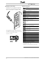
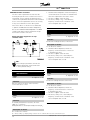
Safety
VLT 5000 FLUX
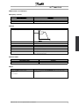
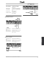
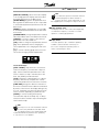
175ZA735.15
■ Software version
Operating Instructions
Software version: 5.5x
Warning:
Touching the electrical parts may be fatal - even after the equipment
has been disconnected from mains.
Also make sure that other voltage inputs have been disconnected,
such as external 24 V DC, load-sharing (linkage of DC intermediate
circuit), as well as the motor connection for kinetic back-up.
Using VLT 5001-5006, 200-240 V:
wait at least 4 minutes
Using VLT 5008-5052, 200-240 V:
wait at least 15 minutes
Using VLT 5001-5006, 380-500 V:
wait at least 4 minutes
Using VLT 5008-5062, 380-500 V:
wait at least 15 minutes
Using VLT 5072-5302, 380-500 V:
wait at least 20 minutes
Using VLT 5352-5502, 380-500 V:
wait at least 40 minutes
MG.55.A7.02 - VLT is a registered Danfoss trademark
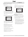
175ZA901.11
These Operating Instructions can be used for VLT 5000 FLUX
frequency converters with software version 5.5x.
The software version number can be seen from parameter 624.
3
VLT® 5000 FLUX
The voltage of the frequency converter
is dangerous whenever the equipment
is connected to mains. Incorrect
installation of the motor or the frequency converter
may cause damage to the equipment, serious
personal injury or death.
Consequently, the instructions in this manual,
as well as national and local rules and safety
regulations, must be complied with.
■ Warning against unintended start
1. The motor can be brought to a stop by
means of digital commands, bus commands,
references or a local stop, while the frequency
converter is connected to mains.
If personal safety considerations make it necessary
to ensure that no unintended start occurs, these
stop functions are not sufficient.
2. While parameters are being changed, the
■ Safety regulations
motor may start. Consequently, the stop key
1. The frequency converter must be disconnected
[STOP/RESET] must always be activated, following
from mains if repair work is to be carried out. Check
which data can be modified.
that the mains supply has been disconnected
3. A motor that has been stopped may start if faults
and that the necessary time has passed before
occur in the electronics of the frequency converter,
removing motor and mains plugs.
or if a temporary overload or a fault in the supply
2. The [STOP/RESET] key on the control panel of
mains or the motor connection ceases.
the frequency converter does not disconnect
■ Installation of mechanical brake
the equipment from mains and is thus not to
be used as a safety switch.
Do not connect a mechanical brake to the output
3. Correct protective earthing of the equipment
from the frequency converter before the relevant
must be established, the user must be protected
parameters for brake control are parameterised.
against supply voltage, and the motor must be
(Selection of output in parameter 319, 321,
protected against overload in accordance with
323 or 326 and cut-in current and frequency
applicable national and local regulations.
in parameter 223 and 225).
4. The earth leakage currents are higher than 3.5 mA.
5. Protection against motor overload is not included
■ Use on isolated mains
in the factory setting. If this function is desired,
See section RFI Switch regarding use on isolated mains.
set parameter 128 to data value ETR trip or
It is important to follow the recommendations regarding
data value ETR warning.
installation on IT-mains, since sufficient protection
Note: The function is initialised at 1.16 x rated
of the complete installation must be observed.
motor current and rated motor frequency. For
Not taking care using relevant monitoring devices
the North American market: The ETR functions
for IT-mains may result in damage.
provide class 20 motor overload protection
in accordance with NEC.
6. Do not remove the plugs for the motor and main
supply while the frequency converter is connected
to mains. Check that the mains supply has been
disconnected and that the necessary time has
expired before removing motor and mains plugs.
7. Please note that the frequency converter has more
voltage inputs than L1, L2 and L3, when loadsharing
(linking of DC intermediate circuit) and external 24 V
DC have been installed. Check that all voltage inputs
have been disconnected and that the necessary
time has passed before repair work is commenced.
4
MG.55.A7.02 - VLT is a registered Danfoss trademark
VLT® 5000 FLUX
■ Abbreviations and Definitions
■ Frequency converter
Abbreviation/Definition
Description
IVLT,MAX
The maximum output current of the frequency converter.
IVLT,N
The rated output current of the frequency converter.
UVLT,MAX
The maximum output voltage.
■ Output
Abbreviation/Definition
Description
Introduction
Break-away torque
fM
The frequency transmitted to the motor
IM
The current transmitted to the motor
nmin
Minimum speed [rpm]
nmax
Maximum speed [rpm]
nJOG
Speed by jog operation [rpm]
UM
The voltage transmitted to the motor
ηVLT
The efficiency of the frequency converter is defined as the ratio between the
power output and power input
■ Switch NO/NC
Abbreviation/Definition
Description
NO
Normally open
NC
Normally closed
■ Input
Abbreviation/Definition
Description
Control command
By means of LCP and the digital inputs, it is possible to start and stop the
Immediate stop
connected motor.
Stop command
MG.55.A7.02 - VLT is a registered Danfoss trademark
5
VLT® 5000 FLUX
■ Motor
Abbreviation/Definition
Description
fM,N
The rated motor frequency (nameplate data)
IM,N
The rated motor current (nameplate data)
I0
Idle current
nM,N
The rated motor speed (nameplate data)
nslip
Slip in motor speed
PM,N
The rated power delivered by the motor (nameplate data)
P0
Power losses at idle state
RFe
Iron loss resistance
R2’
Rotor resistance
RS
Stator resistance
TM,N
The rated torque (motor)
UM,N
The rated motor voltage (nameplate data)
X1σ
Stator Leakage Reactance
X’2σ
Rotor Leakage Reactance
Xh
Main Reactance
■ References
Abbreviation/Definition
Description
Analogue ref.
A signal transmitted to input 53, 54 or 60. Can be voltage or current
Binary ref.
A signal transmitted to the serial communication port
RefMAX
The maximum value which the reference signal may have. Set in parameter 205
■ Miscellaneous
Abbreviation/Definition
Analogue inputs
Description
The analogue inputs can be used for controlling various functions of the frequency converter. There are
two types of analogue inputs:
Current input and voltage input
Analogue outputs
There are two analogue current outputs
AWG
Means American Wire Gauge, ie. the American measuring unit for cable cross-section
Brake resistor
The brake resistor is a module capable of absorbing the brake power that is generated in regenerative
braking. This regenerative braking power increases the intermediate circuit voltage and a brake chopper
ensures that the power is transmitted to the brake resistor
ccw
Counter Clockwise rotation
CL
Closed Loop
Coast (motor)
The motor is free running to stop
CP
Constant power
CT characteristics
Constant torque characteristics, used for all applications, such as conveyor belts and cranes.
cw
Clockwise rotation
DC Link
Intermediate circuit in the frequency converter
Digital inputs
The digital inputs can be used for controlling various functions of the frequency converter
Digital outputs
There are four digital outputs, two of which activate relay switches.
DSP
Digital Signal Processing. The FLUX processor is defined as a DSP
6
MG.55.A7.02 - VLT is a registered Danfoss trademark
VLT® 5000 FLUX
■ Miscellaneous- continued
Abbreviations/Definitions
Description
ED
Duty cycle
ELCB
Earth Leakage Circuit Breaker
ETR
Electronic thermal relay is a thermal load calculation based on present load and
time. Its purpose is to estimate the motor temperature
Flux Vector
If compared with standard voltage/frequency ratio control, Flux Vector improves
the dynamics and the stability, both when the speed reference is changed and
in relation to the load torque
Incremental encoder
An external, digital pulse transmitter used for feeding back information on motor
speed. The encoder is used in applications where high accuracy in speed control
is required
Initializing
If initializing is carried out (see parameter 620), the frequency converter returns to
Semiconductor temperature sensor
LCP
The Local Control Panel, which makes up a complete interface for control and
Introduction
the factory setting
KTY
programming of the frequency converter. The control panel is detachable and
may, as an alternative, be installed up to 3 metres away from the frequency
converter, ie. in a front panel, by means of the installation kit option
Manual initialisation
Press the [CHANGE DATA] + [MENU] + [OK] keys at the same time as power-up
to carry out manual initialisation. See also Parameter 620.
Note that manual initialisation is only to be used if the reset function does not work!
MCM
Stands for Mille Circular Mil, an American measuring unit for cable cross-section
1 MCM=0.5067mm2
NEC
National Electrical Code
NTC
Negative Temperature Coefficient resistor
On-line/off-line parameters
On-line parameters are activated immediately after the data value is changed.
Off-line parameters are not activated until OK has been entered on the control unit
OP
Open Loop
OVC
Over Voltage Control
PELV
Protective Electrical Low Voltage. According to EN 50178
ppr
Puls per revolutions
RPM
Revolutions per minute
Thermistor
A temperature-dependent resistor placed where the temperature is to be
monitored (VLT or motor)
Trip
A state which occurs in different situations, eg. if the frequency converter is
subject to a live zero warning. A trip can be cancelled by pressing Reset
Trip locked
A state which occurs in different situations, eg. if the frequency converter is
subject to an overtemperature. A locked trip can be cancelled by cutting off
mains and restarting the frequency converter and pressing Reset
MG.55.A7.02 - VLT is a registered Danfoss trademark
7
VLT® 5000 FLUX
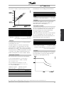
■ Technology
■ Control Principle
A frequency converter rectifies AC voltage from mains
into DC voltage. This DC voltage is then converted into
a AC voltage with a variable amplitude and frequency.
1. Mains voltage
3 x 400 - 500 V AC, 50 / 60 Hz.
2. Rectifier
A three-phase rectifier bridge that rectifies AC
voltage into DC voltage.
3. Intermediate circuit
The motor is thus supplied with variable voltage and
frequency, which enables infinitely variable speed
control of three-phased, standard AC motors.
5. Intermediate circuit capacitors
Smooth the intermediate circuit voltage.
6. Inverter
Converts DC voltage into variable AC voltage
with a variable frequency.
7. Motor voltage
Variable AC voltage, 0-100% of mains supply voltage.
Variable frequency: 0 - 300 Hz.
4. Intermediate circuit coils
Smooth the intermediate circuitcurrent and limit the
load on mains and components (mains transformer,
wires, fuses and contactors).
■ Flux Vector Control Principle
The aim of developing the Flux Vector control
principle has been to obtain a robust motor control
that is tolerant to different motor characteristics
without motor derating being required.
The current is split into magnetising and
torque-generating parts and provides for much
better and quicker estimation of the actual motor
loads. It is now possible to compensate for rapid
load changes. Full torque as well as extremely
accurate speed control can now be obtained even
at low speeds or even at standstill.
Good torque control properties and smooth transitions
to and from current limit operation are ensured.
Advantages of the Flux Vector control system:
- Accurate speed control down to 0 speed
- Quick response from received signal to
full motor shaft torque
- Good compensation for step loads
8
8. Control circuit
On basis of parameters, reference settings and input
signals, pulse patterns are generated for forming
the variable motor voltage and frequency.
-
-
Controlled transition from normal operation to
current limit operation (and vice versa)
Torque control, comprising control of both
the torque-generating and the magnetising
component of the current
Full holding torque
Programmable signal outputs
The frequency converter uses a digital technique which
makes it possible to program the signal outputs.
For the user, it is easy to program the desired functions
by means of the control panel on the frequency
converter or the RS 485/RS 232 user interfaces.
Protection against mains interference
The frequency converter is protected against the
transients that occur in the mains supply, eg. when
switching power factor correction or when fuses blow.
The rated motor voltage and full torque can be
maintained all the way down to 10% undervoltage
in the mains supply.
MG.55.A7.02 - VLT is a registered Danfoss trademark
VLT® 5000 FLUX
Minor interference on mains
Since as standard the frequency converter features
intermediate circuit coils, there is only a small amount
of harmonic mains supply interference. This ensures
a good power factor and lower peak current, which
reduces the load on the mains installation.
Advanced VLT protection
Current measurement on all three motor phases
provides perfect protection of the frequency
converter against earthing and short-circuiting
faults on the motor connection.
Introduction
Efficient monitoring of the three mains supply phases
ensures that the unit stops in the case of phase failure.
This avoids overloading the inverter and the capacitors
in the intermediate circuit, which would dramatically
reduce the service life of the frequency converter.
As standard, the frequency converter features integral
thermal protection. If a situation of thermal overload
occurs, this function cuts out the inverter.
Reliable galvanic isolation
In the frequency converter all of the control circuits
are separated from mains potential through isolation
meeting the PELV requirements.
One set of relay contacts, terminals 01 - 03, is
separated from the remaining control circuits through
isolation also complying with PELV.
Furthermore, the control circuits are placed in blocks
individually separated through functional isolation (<
100 V), see section General Technical Data.
Advanced motor protection
The frequeny converter features integrated electronic,
thermal motor protection.
The frequency converter calculates the motor
temperature on the basis of current, frequency and time.
As opposed to the traditional bimetallic protection,
electronic protection takes account of the reduction in
cooling at low frequencies that comes from reduced
fan speed (motors with internal ventilation).
To obtain maximum protection against overheating of
the motor if the motor is covered or blocked, or if the
fan fails, a thermistor can be integrated and connected
to the thermistor input of the frequency converter
(terminals 53 or 54), see parameters 128, 308 and 311.
MG.55.A7.02 - VLT is a registered Danfoss trademark
9
VLT® 5000 FLUX
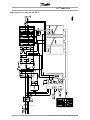
■ Key Diagram for VLT 5001–5027
10
200-240 V, VLT 5001–5102 380-500 V
MG.55.A7.02 - VLT is a registered Danfoss trademark
VLT® 5000 FLUX
Introduction
■ Key Diagram for VLT 5122-5502 380-500 V
MG.55.A7.02 - VLT is a registered Danfoss trademark
11
VLT® 5000 FLUX
■ Key Diagram for VLT 5032–5052 200–240 V
12
MG.55.A7.02 - VLT is a registered Danfoss trademark
VLT® 5000 FLUX
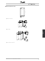
■ Mechanical dimensions
All the below listed measurements are in mm.
A
B
C
395
90
395
D
a
b
ab/be
Type
260
384
70
100
A
130
260
384
70
100
A
800
1046
1327
1896
370
408
408
1099
335
3752)
3752)
494
780
1001
1282
1847
270
304
304
1065
225
225
225
4001)
B
J
J
I
395
220
160
384
200
100
C
395
220
200
384
200
100
C
560
242
260
540
200
200
D
700
242
260
680
200
200
D
800
308
296
780
270
200
D
800
370
335
780
330
225
D
954
1208
1588
2010
370
420
420
1200
335
3732)
3732)
600
780
1154
1535
-
270
304
304
225
225
225
4001
E
J
J
H
460
282
195
85
260
258
100
F
530
282
195
85
330
258
100
F
810
350
280
70
560
326
200
F
940
400
280
70
690
375
200
F
937
940
1208
1588
2010
495
400
420
420
1200
421
360
3732)
3732)
600
70
-
830
690
1154
1535
-
374
375
304
304
225
225
225
225
4001)
G
F
J
J
H
Bookstyle IP 20
5001 - 5003 200 - 240 V
5001 - 5005 380 - 500 V
5004 - 5006 200 - 240 V
5006 - 5011 380
Compact IP 00
5032 - 5052 200
5122 - 5152 380
5202 - 5302 380
5352 - 5502 380
Compact IP 20
5001 - 5003 200
- 500 V
-
240
500
500
500
V
V
V
V
- 240 V
5001 - 5005 380 - 500 V
5004 - 5006 200 - 240 V
5006 - 5011 380 - 500 V
5008 200 - 240 V
5016 - 5022 380 - 500 V
5011 - 5016 200 - 240 V
5042 - 5062 380 - 500 V
5072 - 5102 380 - 500 V
Compact Nema 1/IP20/IP21
5032 - 5052 200 - 240 V
5122 - 5152 380 - 500 V
5202 - 5302 380 - 500 V
5352 - 5502 380 - 500 V
Compact IP 54/Nema 12
5001 - 5003 200 - 240 V
-
Technical
data
5027 - 5032 380 - 500 V
5022 - 5027 200 - 240 V
5001 - 5005 380 - 500 V
5004 - 5006 200 - 240 V
5006 - 5011 380 - 500 V
5008 - 5011 200 - 240 V
5016 - 5027 380 - 500 V
5016 - 5027 200 - 240 V
5032 - 5062 380 - 500 V
5032 - 5052 200 - 240 V
5072 - 5102 380 - 500 V
5122 - 5152 380 - 500 V
5202 - 5302 380 - 500 V
5352 - 5502 380 - 500 V
ab: Minimum space above enclosure’
-
-
be: Minimum space below enclosure
1: Only above enclosure (ab) IP 00 when built in a
Rittal cabinet.
2: With disconnect, add 42 mm.
MG.55.A7.02 - VLT is a registered Danfoss trademark
13
VLT® 5000 FLUX
■ Mechanical dimensions, cont.
14
MG.55.A7.02 - VLT is a registered Danfoss trademark
VLT® 5000 FLUX
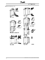
■ Mechanical dimensions (cont.)
Type H, IP 20, IP 54
Technical
data
Type I, IP 00
Type J, IP 00, IP 21, IP 54
MG.55.A7.02 - VLT is a registered Danfoss trademark
15
VLT® 5000 FLUX
Please pay attention to the requirements
that apply to integration and field mounting
kit, see the below list. The information given
in the list must be observed to avoid serious damage
or injury, especially when installing large units.
All frequency converters can be mounted side
by side/flange by flange.
The frequency converter must be installed vertically.
The frequency converter is cooled by means of air
circulation. For the unit to be able to release its cooling
air, the minimum distance over and below the unit
must be as shown in the illustration below.
To protect the unit from overheating, it must be ensured
that the ambient temperature does not rise above the
max. temperature stated for the frequency converter
and that the 24-hour average temperature is not
exceeded. The max. temperature and 24-hour average
can be seen from the General Technical section.
Derating of the frequency converter is required by
ambient temperature in the range of 45° C - 55° C.
See the section Derating in the Design Guide.
Service Life Time of the frequency converter will
be reduced if no derating is carried out in the
above ambient temperature range.
■ Enclosure type
IP 20/Nema 1
IP 54
Bookstyle
IP 00
-
OK
-
Compact
OK
OK
OK
■ Installation of VLT 5001-5502
All frequency converters must be installed in a
way that ensures proper cooling.
Cooling
All Bookstyle and Compact units require a minimum
space above and below the enclosure.
Side by side/flange by flange
16
MG.55.A7.02 - VLT is a registered Danfoss trademark
VLT® 5000 FLUX
d [mm]
Comments
Bookstyle
VLT 5001-5006, 200-240 V
VLT 5001-5011, 380-500 V
100
100
Installation on a plane, vertical surface (no spacers)
Compact (all enclosure types)
VLT 5001-5006, 200-240 V
VLT 5001-5011, 380-500 V
100
100
Installation on a plane, vertical surface (no spacers)
VLT 5008-5027, 200-240 V
VLT 5016-5062, 380-500 V
VLT 5072-5102, 380-500 V
200
200
225
Installation on a plane, vertical surface (no spacers)
VLT 5032-5052, 200-240 V
VLT 5122-5302, 380-500 V
225
225
VLT 5352-5502, 380-500 V
225
Installation on a plane, vertical surface (no spacers)
IP 54 filter mats must be changed when they are dirty.
IP 00 above and below enclosure
Installation
IP 21/IP 54 only above enclosure
MG.55.A7.02 - VLT is a registered Danfoss trademark
17
VLT® 5000 FLUX
■ Installation of VLT 5352-5502 380-500 V Compact
Nema 1 (IP 21) and IP 54
Cooling
Side-by-side
Compact Nema 1 (IP 21) and IP 54
All units in the above-mentioned series require a
minimum space of 225 mm above the enclosure and
must be installed on a flat level surface. This applies
to both Nema 1 (IP 21) and IP 54 units.
Gaining access to the VLT 5352-5502 requires
a minimum space of 579 mm in front of the
frequency converter.
All Nema 1 (IP 21) and IP 54 units in the
above-mentioned series can be installed side by
side without any space between them, since these
units do not require cooling on the sides.
Filter mats in IP 54 units have to be changed regularly
depending on the operating environment.
18
MG.55.A7.02 - VLT is a registered Danfoss trademark
VLT® 5000 FLUX
■ Electrical installation
The voltage on the frequency converter is
dangerous when the unit is connected to
mains. Incorrect installation of the motor or
the frequency converter may lead to material damage
or serious injury or it may be fatal. Consequently, the
instructions in this manual as well as national and local
rules and safety regulations must be complied with.
Touching the electrical parts may be fatal, even after
the mains supply has been disconnected.
Using VLT 5001-5006, 200-240 V and 380-500
V: wait at least 4 minutes.
Using VLT 5008-5052, 200-240 V: wait
at least 15 minutes.
Using VLT 5008-5062, 380-500 V: wait
at least 15 minutes.
Using VLT 5072-5302, 380-500 V: wait
at least 20 minutes.
Using VLT 5352-5502, 380-500 V: wait
at least 40 minutes.
NB!:
It is the user’s or certified electrician’s
responsibility to ensure correct earthing and
protection in accordance with applicable
national and local norms and standards.
■ Terminal designation
The terminal designations for power connections
are equal for all sizes of VLT inverters.
Mains terminals
Motor terminals
Earth terminals
Brake resistor
terminals
Load sharing
91
R (L1)
96
U
94
92
S (L2)
97
V
95
81
R+
88
-DC
82
R89
+DC
93
T (L3)
98
W
99
■ Electrical installation - mains supply
Connect the three mains phases to terminals L1, L2, L3.
■ Motor connection
All types of 3-phased asynchronous standard motors
can be used with the frequency converter.
NB!:
The RFI switch must be closed (position
ON) when high voltage tests are carried
out (see section RFI Switch).
The mains and motor connection must be interrupted
in the case of high voltage tests of the total installation
if the leakage currents are too high.
■ Safety earthing
NB!:
The frequency converter has a high leakage
current and must be earthed appropriately
for safety reasons. Use earth terminal
(see section Electrical installation, power cables),
which enables reinforced earthing.
Apply national safety regulations.
MG.55.A7.02 - VLT is a registered Danfoss trademark
Normally, small motors are star-connected
(200/400 V,
/Y).
Large motors are delta-connected (400/690 V,
Please be aware, that the motor cable must
be screened.
/Y).
■ Motor thermal protection
The electronic thermal relay in UL-approved frequency
converters has received the UL-approval for single
motor protection when parameter 128 has been set for
ETR Trip and parameter 105 has been programmed to
the rated motor current (see motor nameplate).
19
Installation
■ High voltage test
A high voltage test can be carried out by shortcircuiting terminals U, V, W, L1, L2 and L3 and
energizing by max. 2.15 kV DC for one second
between this short-circuit and the chassis.
VLT® 5000 FLUX
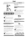
■ Motor shaft direction
■ Electrical installation - brake resistor
temperature switch
Torque: 0.5-0.6 Nm
Screw size: M3
No.
106, 104,
105
The factory setting is for clockwise rotation with the
frequency converter output connected as follows:
CW
U
96
V
97
W
98
CCW
U
96
V
98
W
97
Function
Brake resistor temperature switch.
NB!:
This function is only available on VLT 5032-5052
200-240 V and VLT 5125-5502 380-500 V.
If the temperature of the brake resistor
gets too high and the thermal switch drops
out, the frequency converter will stop braking.
The motor will start coasting.
A KLIXON switch must be installed that is ‘normally
closed’. If this function is not used, 106 and 104
must be short-circuited together.
The direction of rotation can be changed by switching
two phases in the motor cable.
NB!:
If the application is running in closed loop with
an encoder as feedback signal, the encoder
signal A,A/B,B/ wires must be swopped or the
encoder direction must be changed in parameter 351.
NB!:
Flux vector drives can operate with one
motor only. It is not possible to run
parallel-connected motors on the output
side of the frequency converter.
■ Electrical installation - loadsharing
(Only extended with typecode EB, EX, DE, DX).
No.
88, 89
Function
Loadsharing
Terminals for loadsharing
■ Electrical installation - brake cable
(Only standard with brake and extended with
brake. Typecode: SB, EB, DE, PB).
No.
81, 82
Function
Brake resistor terminals
The connection cable to the brake resistor must be
screened. Connect the screen by means of cable
clamps to the conductive back plate at the frequency
converter and to the metal cabinet of the brake resistor.
Size the brake cable cross-section to match
the brake torque. See also Brake instructions,
MI.90.FX.YY and MI.50.SX.YY for further information
regarding safe installation.
The connection cable must be screened and
the max. length from the frequency converter
to the DC bar is 25 metres.
Load sharing enables linking of the DC intermediate
circuits of several frequency converters.
NB!:
Please note that voltages up to 1099 V DC
may occur on the terminals.
Load sharing calls for extra equipment. For
further information please consult Loadsharing
Instructions MI.50.NX.XX.
NB!:
Please note that voltages up to 1099 V
DC, depending on the supply voltage, may
occur on the terminals.
20
MG.55.A7.02 - VLT is a registered Danfoss trademark
VLT® 5000 FLUX
■ Tightening-up torques and screw sizes
The table shows the torque required when fitting
terminals to the frequency converter. For VLT
5001-5027 200-240 V and VLT 5001-5102 380-500
V, the cables must be fastened with screws. For VLT
5032-5052 200-240 V and VLT 5122-5502 380-500
V, the cables must be fastened with bolts.
These figures apply to the following terminals:
VLT type
200-240 V
5001-5006
5008
5008-5011
5011-5022
5016-50223)
5027
5032-50521)
380-500 V
5001-5011
5016-5022
5016-5027
5027-5042
5032-50423)
5052-5062
5072-5102
Torque [Nm]
IP20
IP54
IP20
IP54
Nos
91, 92, 93
L1, L2, L3
Motor terminals
Nos
96, 97, 98
U, V, W
Earth terminal
No
94, 95, 99
Brake resistor terminals
81, 82
Loadsharing
88, 89
0,6
1,8
1,8
3
3
6
11,3
Screw/
Boltsize
M3
M4
M4
M5
M5
M6
M8 (bolt and stud)
0,6
1,8
1,8
3
3
6
15
24
19
42
M3
M4
M4
M5
M5
M6
M6
M8
M10 bolt
M12 bolt
IP20
IP54
IP20
IP54
IP20
IP542)
5122-53024)
5352-55025)
Tool
Slotted screw
Slotted screw
Slotted screw
4 mm Allen wrench
4 mm Allen wrench
4 mm Allen wrench
4
4
5
6
8
Slotted screw
Slotted screw
Slotted screw
mm Allen wrench
mm Allen wrench
mm Allen wrench
mm Allen wrench
mm Allen wrench
Brake terminals: 3,0 Nm, Nut: M6
Brake and loadsharing: 14 Nm, M6 Allen screw
IP54 with RFI - Line terminals 6Nm, Screw: M6 - 5 mm Allen wrench
Loadshare and brake terminals: 9,5 Nm; Bolt M8
Brake terminals: 11,3 Nm; Bolt M8
Installation
1)
2)
3)
4)
5)
Mains terminals
MG.55.A7.02 - VLT is a registered Danfoss trademark
21
VLT® 5000 FLUX
■ Electrical installation - external fan supply
Torque 0,5-0,6 Nm
Screwsize: M3
Screw size: M3
No.
1-3
4, 5
Function
Relay output, 1+3 break, 1+2 make
See parameter 323 of the Operating
Instructions. See also General
technical data.
Relay output, 4+5 make See
parameter 326 of the Operating
Instructions.
See also General technical data.
Available in 5122-5502, 380-500 V; 5032-5052,
200-240 V in all enclosure types.
Only for IP54 units in the power range VLT 5016-5102,
380-500 V and VLT 5008-5027, 200-240 V AC. If
the drive is supplied by the DC bus (loadsharing), the
internal fans are not supplied with AC power. In this
case they must be supplied with an external AC supply.
■ Electrical installation - 24 Volt external DC supply
(Only extended versions. Typecode: PS, PB,
PD, PF, DE, DX, EB, EX).
Torque: 0.5 - 0.6 Nm
Screw size: M3
No.
35, 36
Function
24 V external DC supply
External 24 V DC supply can be used as low-voltage
supply to the control card and any option cards
installed. This enables full operation of the LCP (incl.
parameter setting) without connection to mains.
Please note that a warning of low voltage will be
given when 24 V DC has been connected; however,
there will be no tripping. If 24 V external DC supply
is connected or switched on at the same time as
the mains supply, a time of min. 200 msec. must
be set in parameter 120 Start delay.
A pre-fuse of min. 6 Amp, slow-blow, can be
fitted to protect the external 24 V DC supply.
The power consumption is 15-50 W, depending
on the load on the control card.
NB!:
Use 24 V DC supply of type PELV to ensure
correct galvanic isolation (type PELV) on the
control terminals of the frequency converter.
■ Electrical installation - relay outputs
Torque: 0.5 - 0.6 Nm
22
MG.55.A7.02 - VLT is a registered Danfoss trademark
VLT® 5000 FLUX
■ Extra protection (RCD)
ELCB relays, multiple protective earthing or earthing
can be used as extra protection, provided that local
safety regulations are complied with.
In the case of an earth fault, a DC content may
develop in the faulty current.
If ELCB relays are used, local regulations must be
observed. Relays must be suitable for protection
of 3-phase equipment with a bridge rectifier and
for a brief discharge on power-up.
■ Earth leakage current
Earth leakage current is primarily caused by the
capacitance between motor phases and the motor
cable screen. When an RFI filter is used, this
contributes additional leakage current, as the filter
circuit is connected to earth through capacitors.
The size of the leakage current to the ground depends
on the following factors, in order of priority:
1.
2.
3.
4.
5.
Length of motor cable
Motor cable with or without screen
Switching frequency
RFI filter used or not
Motor grounded on site or not
The leakage current is of importance to safety during
handling/operation of the frequency converter if (by
mistake) the frequency converter has not been earthed.
Installation
NB!:
Since the leakage current is >3.5 mA, reinforced
earthing must be established, which is required
if EN 50178 is to be complied with. For
3-phased frequency converters, only fault current
relays which are suitable for protection against DC
currents (Din VDE 0664) are to be used. RCD fault
current relays type B comply with these requirements
according to the norm IEC 755-2.
The following requirements must be complied with:
- Suitable for protecting equipment with a
direct current content (DC) in the fault
current (3-phase rectifier)
- Suitable for power-up with short pulse-shaped
charging current to earth
- Suitable for a high leakage current.
MG.55.A7.02 - VLT is a registered Danfoss trademark
23
VLT® 5000 FLUX
■ Electrical installation, power cables
Compact IP 20/Nema 1
Compact IP 54
Bookstyle
VLT 5001-5006 200-240 V
VLT 5001-5011 380-500 V
24
MG.55.A7.02 - VLT is a registered Danfoss trademark
VLT® 5000 FLUX
Compact
VLT 5001-5006 200-240 V
VLT 5001-5011 380-500 V
■ Electrical installation, power cables
Compact IP 20
VLT 5072-5102 380-500 V
Installation
Compact IP 20/Nema 1
VLT 5008-5027 200-240 V
VLT 5016-5102 380-500 V
Compact IP 20/Nema 1
VLT 5008-5027 200-240 V
VLT 5016-5062 380-500 V
MG.55.A7.02 - VLT is a registered Danfoss trademark
25
VLT® 5000 FLUX
Compact IP 54
VLT 5008-5027 200-240 V
VLT 5016-5062 380-500 V
26
Compact IP 54
VLT 5072-5102 380-500 V
MG.55.A7.02 - VLT is a registered Danfoss trademark
Compact IP 00 with disconnect and fuse
VLT 5202-5302 380-500 V
Compact IP 21/IP54 without disconnect and fuse
VLT 5122-5152 380-500 V
Compact IP 21/IP54 with disconnect and fuse
VLT 5202-5302 380-500 V
Installation
Compact IP 00 without disconnect and fuse
VLT 5122-5152 380-500 V
MG.55.A7.02 - VLT is a registered Danfoss trademark
27
Installation
VLT® 5000 FLUX
VLT® 5000 FLUX
Compact IP 21 / IP 54 without disconnect and fuse
VLT 5352-5502 380-500 V
Compact IP 00 with disconnect and fuse
VLT 5352-5502 380-500 V
Position of earth terminals, IP 00
Compact IP 00 without disconnect and fuse
VLT 5352-5502 380-500 V
Position of earth terminals, IP 21 / IP 54
28
MG.55.A7.02 - VLT is a registered Danfoss trademark
VLT® 5000 FLUX
Installation
■ Electrical installation, power cables
Compact IP 00/NEMA 1 (IP 20)
VLT 5032-5052 200-240 V
Compact IP 54
VLT 5032-5052 200-240 V
MG.55.A7.02 - VLT is a registered Danfoss trademark
29
VLT® 5000 FLUX
■ Installation of Control Cables
All terminals for the control cables are located under
the protective cover of the frequency converter. The
protective cover (see drawing) can be removed by
means of a pointed object - a screwdriver or similar.
■ Terminal Designation
No.
04, 05
Function
Relay output
+24 VDC. Supply to digital inputs Imax: 200 mA.
12, 13
No connection when external 24 VDC supply is
20
16
used and DIP SW4 off
GND for digital inputs (External 24 VDC connection)
Digital Input 1. Parameter 300 [1] {RESET} 1)
Digital Input 2. Parameter 301 [7] {FREEZE
17
REFERENCE}1)
Digital Input 3. Parameter 302 [1] {START}1)
Digital Input 4. Parameter 303 [1] {REVERSING}1)
Digital Input 5. Parameter 304 [0] {COASTING
18
19
27
STOP}1)
Digital Input 6. Parameter 305 [5] {JOG}1)
Digital Input 7. Parameter 306 [11]
29
32
{Set-up MSB / SPEED UP}1)
Digital 8. Parameter 307 [1] {Set-up LSB / SPEED
DOWN}1)
33
Digital Input. Hardware Coast. No parameter
37
39
26, 46
42, 45
Once the protective cover has been removed, the
actual EMC-correct installation can start. See drawings
in the section, EMC correct installation.
Connection of shield:
influence. Disable output stage.
GND for analogue and digital outputs
Digital Outputs for readout of speed, reference,
current or torque
Analogue Outputs for readout of speed, reference,
current or torque
+10 VDC supply for analogue reference inputs as
50
external potentiometers, thermistor or KTY sensor.
55
53
54
60
68, 69
49
47
73
74
75
76
77
78
Imax <12 mA
GND for analogue reference inputs
Analogue reference input ±10 V
Analogue reference input ±10 V
Analogue reference input 0/4 - 20 mA.
RS 485 Interface, serial communication.
+5 VDC supply for encoder.
GND for supply for encoder
Channel A 2)
Channel A inverted 2)
Channel B 2)
Channel B inverted 2)
Zero pulse from encoder (Z)
Zero pulse from encoder inverted
1) Factory settings. If other functionalities
see parameters 300 - 307
2) Usually for clockwise turning of encoder shaft.
30
MG.55.A7.02 - VLT is a registered Danfoss trademark
VLT® 5000 FLUX
Terminal 37 is a "Hardware Coast" input function
for disabling the output stages (inverter). Terminal
37 cannot be disabled, handled or adjusted by
any parameters. Terminal 37 must be pulled up
to 24 V DC for the unit to work.
Installation of Control Cables
Tightening-up torque: 0.22 - 0.25 Nm
Screw size: M2
Screw driver type: 0.4 x 2.5 x 80 mm
See Earthing of Braided Screened/Armoured
Control Cables for correct earthing.
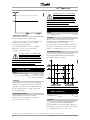
■ Feedback System
The feedback system is necessary when the drive is
set to closed loop operation (Parameter 100 [1] or [5] ).
The VLT 5000 Flux accepts incremental encoders
as feedback system from motor.
Connection of encoder
VLT 5000 Flux supports most types of 4 channel + zero
pulse incremental encoders as feedback device.
Power
supply
Max cable
length
5 V DC max 250 mA
(Encoder power consumption max
0.75 watt).
(according to RS422 spec) < 150 m
If longer cables are used, please
contact Danfoss Drives.
Typical impulse pattern from an incremental encoder
LEDs on encoder board:
Installation
When all LEDs are ON the connection to encoder
and encoder condition are OK.
LED 403 OFF: 5 V supply missing
LED 400 OFF: Channel A or inv. A missing
or shortcircuited
LED 401 OFF: Channel B or inv. B missing
or shortcircuited
LED 402 OFF: Channel Z or inv. Z missing
or shortcircuited.
Basic encoder connection
MG.55.A7.02 - VLT is a registered Danfoss trademark
31
VLT® 5000 FLUX
The encoder surveillance circuit must be switched
off in parameter 350 [0].
If the encoder has no inverted outputs, the encoder
cable can only have a length of max 3 meter. The
encoder input must then be terminated as shown.
If the encoder has no zero pulse, and the encoder
monitor is enabled (parameter 350), the inputs
77 and 78 must be terminated.
■ Electrical installation
Regarding programming of the digital and analog
inputs and outputs, see parameter group 300.
■ Bus connection RS 485
The serial bus connection is connected to terminals
68/69 of the frequency converter (signals P and N) in
32
accordance with the RS 485 (2-wire) norm. Signal
P is the positive potential (TX+,RX+), while signal
N is the negative potential (TX-,RX-).
MG.55.A7.02 - VLT is a registered Danfoss trademark
VLT® 5000 FLUX
If more than one frequency converter is to be connected
to a given master, use parallel connections.
ie. when using eg. the RS 232, the RS 485 plug
must be removed from the board.
Hardware connection of the RS 232:
In order to avoid potential equalizing currents the
circuit driving terminals 68 and 69 are connected to
the VLT chassis ground via a 100 resistor.
Bus termination
The bus must be terminated by a resistor network at
both ends. For this purpose, set switches 2 and 3
on the control card for "ON", see Switches 1-4.
Pin 1 is connected to pin 6 on the control card,
which results in the PC receiving a "Clear to Send"
when it sends a "Request to Send".
Pin 1 is the left terminal on RJ-11.
■ DIP Switches 1-4
The DIP switch is located on the control card.
It is used for serial communication, terminals 68 and 69.
The switching position shown is the factory setting.
Communication cable with an RJ-11 male plug in both
ends and an adaptor between RJ-11 and Sub-D 9
connector (for PC connection) (175Z3217).
Installation
Switch 1 must always be open (off).
Switches 2 and 3 are used for terminating an RS
485 interface, serial communication.
Switch 4 is used for separating the common potential
for the internal 24 V DC supply from the common
potential of the external 24 V DC supply.
NB!:
Please note that when Switch 4 is in position
"OFF", the external DC supply is galvanically
isolated from the frequency converter.
■ Bus Connection RS 232
The purpose of the RS 232 is to enable communication
between a PC and a frequency converter. With this
communication it is possible to monitor, programme
and control the frequency converter.
However, it is not possible to use the RS 232
concurrently with the RS 485. When using one
of the buses, the other must be disconnected,
MG.55.A7.02 - VLT is a registered Danfoss trademark
33
VLT® 5000 FLUX
■ Connection examples
■ 2-wire start/stop
Start (18)
Stop (16)
Jog
Ramp up Time
Ramp down
Time
Jog Speed
Jog Ramp Time
Quick Stop (27)
Parameter 302 Pulse Start [2]
Parameter 300 Stop inverted [2]
Parameter 305 Jog [5]
Parameter 207/209
[0.01…3600]
Parameter 208/210
[0.01…3600]
Parameter 213 [0.0…Parameter
202]
Parameter 211 [0.01… 3600]
Parameter 304 Coasting Stop
inverted [0]
■ Setup change
Start - Stop (18)
Quick Stop (27)
Ramp up Time
Ramp down Time
Quick Stop Ramp
Parameter 302 Start [1]
Parameter 304 Coasting Stop
inverted [0]
Parameter 207/209
[0.01…3600]
Parameter 208/210
[0.01…3600]
Parameter 212 [0.01…3600]
Start - Stop (18)
Active Set-up
Set-up MSB
Set-up LSB
Parameter 302 Start [1]
Parameter 004 Multi-setup [5]
Parameter 306 [11]
Parameter 307 [11]
Select setup 1
Select setup 2
Select setup 3
Select setup 4
Term 33
0
1
0
1
■ Pulse start/stop
Term 32
0
0
1
1
■ Digital speed up/down
34
MG.55.A7.02 - VLT is a registered Danfoss trademark
VLT® 5000 FLUX
Start - Stop (18)
Freeze reference
Higher speed
Lower speed
Ramp up time
Ramp down time
Parameter 302 Start [1]
Parameter 305 Freeze
reference [9
Parameter 306 Speed up [9]
Parameter 307 Speed down
[9]
Parameter 209
[0.01...3600]
Parameter 210
[0.01...3600]
■ Potentiometer reference
Analogue input
(53)
Min Scaling (53)
Max Scaling (53)
Parameter 308 Reference [1]
Parameter 309 [0.0….10.0 V]
Parameter 310 [Parameter
309…10.0 V]
■ Two-wire transmitter
Parameter 314 Reference [1]
Installation
Input Ref 0/4-20
mA
Min Scaling (60)
Max Scaling (60)
Parameter 315 [0.0…20.0 mA]
Parameter 316 [Parameter
315…20.0 mA]
MG.55.A7.02 - VLT is a registered Danfoss trademark
35
VLT® 5000 FLUX
■ Electrical installation - EMC precautions
The following is a guideline to good engineering
practice, when installing drives. Following these
guidelines is advised, where compliance with EN
61000-6-3, EN 61000-6-4, EN 55011 or EN 61800-3
First environment is required. If the installation is in EN
61800-3 Second environment, i.e. industrial networks
or in an installation that has its own transformer, it
is acceptable to deviate from these guidelines. It is
however not recommended. See also CE labelling,
Emission and EMC test results under special conditions
in the Design Guide for further details.
Good engineering practice to ensure EMC-correct
electrical installation:
•
•
•
•
•
•
36
Use only braided screened/armoured motor cables
and braided screened/armoured control cables. The
screen should provide a minimum coverage of 80%.
The screen material must be metal, not limited to
but typically copper, aluminium, steel or lead. There
are no special requirements for the mains cable.
Installations using rigid metal conduits are not
required to use screened cable, but the motor
cable must be installed in conduit separate from
the control and mains cables. Full connection
of the conduit from the drive to the motor is
required. The EMC performance of flexible
conduits varies a lot and information from the
manufacturer must be obtained.
Connect the screen/armour/conduit to earth
at both ends for motor cables as well as for
control cables. In some cases, it is not possible
to connect the screen in both ends. In these
cases, it is important to connect the screen at the
frequency converter. See also Earthing of braided
screened/armoured control cables.
Avoid terminating the screen/armour with
twisted ends (pigtails). Such a termination
increases the high frequency impedance of the
screen, which reduces its effectiveness at high
frequencies. Use low impedance cable clamps
or EMC cable glands instead.
It is important to ensure good electrical contact
between the mounting plate on which the frequency
converter is installed and the metal chassis of the
frequency converter. However, this does not apply
to IP 54 units as they are designed for wall-mounting
and VLT 5122-5552 380-500 V, 5042-5352 525-690
V and VLT 5032-5052 200-240 V in IP20/NEMA
1 enclosure and IP 54/NEMA 12 enclosure.
Use starwashers and galvanically conductive
installation plates to secure good electrical
connections for IP00 and IP20 installations.
•
•
Avoid using unscreened/unarmoured motor or
control cables inside cabinets housing the drive(s),
whenever this can be avoided.
An uninterrupted high frequency connection
between the frequency converter and the motor
units is required for IP54 units.
The illustration shows an example of an EMC-correct
electrical installation of an IP 20 frequency converter;
the frequency converter has been fitted in an installation
cabinet with an output contactor and connected to a
PLC, which in this example is installed in a separate
cabinet. In IP 54 units and VLT 5032-5052, 200-240
V in IP20/IP21/NEMA 1 enclosure screened cables
are connected by using EMC conduits to ensure
proper EMC performance. See illustration. Other
ways of making the installation may have as good
an EMC performance, provided the above guide
lines to engineering practice are followed.
Please note, that when the installation is not carried
through according to the guideline as well as when
unscreened cables and control wires are used, some
emission requirements are not complied with, although
the immunity requirements are fulfilled. See the section
EMC test results in the Design Guide for further details.
MG.55.A7.02 - VLT is a registered Danfoss trademark
Installation
VLT® 5000 FLUX
MG.55.A7.02 - VLT is a registered Danfoss trademark
37
VLT® 5000 FLUX
38
MG.55.A7.02 - VLT is a registered Danfoss trademark
VLT® 5000 FLUX
■ Use of emc-correct cables
Braided screened/armoured cables are recommended
to optimise EMC immunity of the control cables and
the EMC emission from the motor cables.
The ability of a cable to reduce the in- and outgoing
radiation of electric noise depends on the transfer
impedance (ZT). The screen of a cable is normally
designed to reduce the transfer of electric noise;
however, a screen with a lower transfer impedance
(ZT) value is more effective than a screen with a
higher transfer impedance (ZT).
Transfer impedance (ZT) can be assessed on the
basis of the following factors:
- The conductibility of the screen material.
- The contact resistance between the individual
screen conductors.
- The screen coverage, i.e. the physical area
of the cable covered by the screen - often
stated as a percentage value.
- Screen type, i.e. braided or twisted pattern.
Aluminium-clad with copper wire.
Twisted copper wire or armoured steel wire cable.
Single-layer braided copper wire with varying percentage screen
coverage.
This is the typical Danfoss reference cable.
Double-layer braided copper wire.
Twin layer of braided copper wire with a magnetic,
screened/armoured intermediate layer.
Cable that runs in copper tube or steel tube.
Lead cable with 1.1 mm wall thickness.
MG.55.A7.02 - VLT is a registered Danfoss trademark
Installation
Transfer impedance (ZT) is rarely stated by
cable manufacturers, but it is often possible to
estimate transfer impedance (ZT) by assessing
the physical design of the cable.
39
VLT® 5000 FLUX
■ Electrical installation - earthing of control cables
Generally speaking, control cables must be braided
screened/armoured and the screen must be
connected by means of a cable clamp at both
ends to the metal cabinet of the unit.
The drawing below indicates how correct earthing is
carried out and what to be done if in doubt.
Correct earthing
Control cables and cables for serial communication
must be fitted with cable clamps at both ends to
ensure the best possible electrical contact
Wrong earthing
Do not use twisted cable ends (pigtails), since these
increase the screen impedance at high frequencies.
Protection with respect to earth potential
between PLC and VLT
If the earth potential between the frequency converter
and the PLC (etc.) is different, electric noise may
occur that will disturb the whole system. This
problem can be solved by fitting an equalising cable,
to be placed next to the control cable. Minimum
cable cross-section: 16 mm 2.
For 50/60 Hz earth loops
If very long control cables are used, 50/60 Hz earth
loops may occur. This problem can be solved by
connecting one end of the screen to earth via a
100nF capacitor (keeping leads short).
Cables for serial communication
Low-frequency noise currents between two frequency
converters can be eliminated by connecting one end of
the screen to terminal 61. This terminal is connected
to earth via an internal RC link. It is recommended
to use twisted-pair cables to reduce the differential
mode interference between the conductors.
40
MG.55.A7.02 - VLT is a registered Danfoss trademark
VLT® 5000 FLUX
■ RFI switch
Mains supply isolated from earth:
If the frequency converter is supplied from an
isolated mains source ( IT mains), the RFI switch is
recommended to be turned off (OFF). In case optimum
EMC performance is needed, parallel motors are
connected or the motor cable length is above 25 m, it
is recommended to set the switch in ON position.
In OFF position, the internal RFI capacities (filter
capacitors) between the chassis and the intermediate
circuit are cut off to avoid damage to the intermediate
circuit and to reduce the earth capacity currents
(according to IEC 61800-3).
Please also refer to the application note VLT on
IT mains, MN.90.CX.02. It is important to use
isolation monitors that are capable for use together
with power electronics (IEC 61557-8).
NB!:
The RFI switch is not to be operated with
mains connected to the unit. Check that
the mains supply has been disconnected
before operating the RFI switch.
Position of RFI switches
Bookstyle IP 20
VLT 5001 - 5006 200 - 240 V
VLT 5001 - 5011 380 - 500 V
NB!:
Open RFI switch is only allowed at factory
set switching frequencies.
NB!:
The RFI switch disconnects the capacitors
galvanically to ground.
The red switches are operated by means of e.g. a
screwdriver. They are set in the OFF position when
they are pulled out and in ON position when they
are pushed in. Factory setting is ON.
Installation
Compact IP 20/NEMA 1
VLT 5001 - 5006 200 - 240 V
VLT 5001 - 5011 380 - 500 V
Mains supply connected to earth:
The RFI switch must be in ON position in order for the
frequency converter to comply with the EMC-standard.
MG.55.A7.02 - VLT is a registered Danfoss trademark
41
VLT® 5000 FLUX
Compact IP 20/NEMA 1
VLT 5008 200 - 240 V
VLT 5016 - 5022 380 - 500 V
Compact IP 20/NEMA 1
VLT 5022 - 5027 200 - 240 V
VLT 5042 - 5102 380 - 500 V
Compact IP 20/NEMA 1
VLT 5011 - 5016 200 - 240 V
VLT 5027 - 5032 380 - 500 V
Compact IP 54
VLT 5001 - 5006 200 - 240 V
VLT 5001 - 5011 380 - 500 V
42
MG.55.A7.02 - VLT is a registered Danfoss trademark
VLT® 5000 FLUX
Compact IP 54
VLT 5008 - 5011 200 - 240 V
VLT 5016 - 5027 380 - 500 V
Installation
Compact IP 54
VLT 5072 - 5102 380 - 500 V
Compact IP 54
VLT 5016 - 5027 200 - 240 V
VLT 5032 - 5062 380 - 500 V
MG.55.A7.02 - VLT is a registered Danfoss trademark
43
VLT® 5000 FLUX
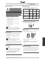
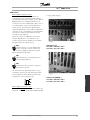
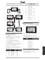
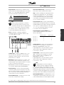
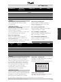
■ Control panel (LCP)
The front of the frequency converter features a
control panel - LCP(Local Control Panel), which
makes up a complete interface for operation and
monitoring of the frequency converter.
The control panel is detachable and can - as an
alternative - be installed up to 3 metres away from
the frequency converter, e.g. on a front panel,
by means of a mounting kit option.
The functions of the control panel can be
divided into three groups:
•
•
•
selected as the Active Setup in parameter 004 is
shown. When programming another Setup than
the Active Setup, the number of the Setup which
is being programmed will appear to the right. This
second Setup number will flash.
■ LEDs
If certain threshold values are exceeded, the red alarm
and/or yellow warning LED light(s) up together with a
status and alarm text on the control panel.
display
keys for changing program parameters
keys for local operation
All data are shown in a 4-line alpha-numeric
display, which in normal operation is able to show
4 measurements and 3 operating conditions
continuously. During programming, all the information
required for quick, effective parameter Setup of the
frequency converter will be displayed. Additional
three LEDs for indicating voltage (power or 24
V external), warning and alarm.
All program parameters can be changed immediately
from the control panel, unless this function has
been blocked via parameter 018.
The ON LED is activated when the frequency converter
is connected to mains, or 24 V external supply; at the
same time the rear lighting of the display will be on.
■ Control keys
The control keys are divided into functions. This means
that the keys between display and indicator lamps
are used for parameter Setup, including choice of
display indication during normal operation.
1. Line
2.Line
3. Line
4. Line
SETUP
1
175ZA734.10
■ Display
1st line shows up to 3 measurements continuously
in normal operating status or a text which
explains the 2 nd line.
2nd line shows a measurement with related
unit continuously, regardless of status (except
in the case of alarm/warning).
Parameter setup keys:
The frequency converter can be used for
practically all assignments and offers a choice
between two programming modes - a Menu
mode and a Quick menu mode.
Menu mode provides access to all parameters.
Quick menu mode takes the user through a few
parameters which make it possible to easy start
operating the frequency converter.
A change of a parameter will take effect and be visible
both in the Menu mode and in the Quick menu mode.
3rd line is normally blank and is used in the menu
mode to show the selected parameter number or
parameter group number and name.
4th line is used in operating status for showing a status
message text or in data change mode for showing
the mode or value of the selected parameter.
An arrow indicates the direction of rotation of the
motor. Furthermore, the Setup which has been
44
MG.55.A7.02 - VLT is a registered Danfoss trademark
VLT® 5000 FLUX
[DISPLAY / STATUS] selects the mode of display
or for changing back to Display mode from either
the Quick menu mode or the Menu mode.
[QUICK MENU] programms the parameters that
belong under the Quick menu mode. It is possible
to switch directly between Quick menu mode and
Menu mode.
[MENU] programms all parameters. It is possible
to switch directly between Menu mode and Quick
menu mode.
[CHANGE DATA ] changes the parameter selected
either in the Menu mode or the Quick menu mode.
[CANCEL] is used if a change of the selected
parameter is not to be carried out.
[OK] confirms a change of the parameter selected.
[+/-] selects parameter and for changing the
chosen parameter or for changing the read out in
line 2.
[<>] is used for selecting group and to move the
cursor when changing numerical parameters.
NB!:
If no external stop function has been selected
and the [Stop] key has been selected as
inactive, the motor can be started and can only
be stopped by disconnecting the voltage to the motor.
■ Display read-out state
The display read-out state can be varied depending
on whether the frequency converter is in normal
operation or is being programmed.
■ Display mode
In normal operation, up to 4 different operating
variables can be indicated continuously: In
line 1 and 2 the present operating status or
alarms, and warnings in line 4.
Local control keys:
[STOP / RESET] stops the motor connected or
resetts the frequency converter after a drop-out
(trip). Can be selected via parameter 014 to be
active or inactive. If stop is activated, line 2 will
flash, and [START] must be activated.
[JOG] overrides the output frequency to a preset
frequency while the key is kept down. Can be
selected via parameter 015 to be active or inactive.
[FWD / REV] changes the direction of rotation of
the motor. Forward or Reverse direction is indicated
by means of the arrow on the display although only
in Local. Parameter 016 selects the function to be
active or inactive, depending on parameter 506.
[START] is used for starting the frequency
converter after stop via the "Stop" key. Is always
active, but cannot override a stop command given
via the terminal strip.
MG.55.A7.02 - VLT is a registered Danfoss trademark
Control Panel
(LCP)
NB!:
If the keys for local control have been selected
as active, they will remain active both when
the speed has been set for Local Control and
for Remote Control via parameter 002. [Fwd/rev]
is only active in Local operation.
45
VLT® 5000 FLUX
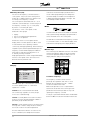
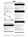
■ Display mode - selection of read-outstate
• Read-out state I:
• Display state IV:
1500 rpm
SETUP
1
This display state can be produced during operation
if another setup is to be changed without stopping
the frequency converter. This function is activated
in parameter 005, Programming Setup.
24.3%
Line 2 shows the data value of an operating variable
with related unit. Line 1 provides a text which explains
line 2. In the example, the speed has been selected as
variable via parameter 009. In normal operation mode
variables can be read out by using the [+/-] keys.
• Read-out state II:
13.8A
1500 rpm
SETUP
1 2
175ZA737.11
Switching between read-out states I and II is effected by
pressing the [DISPLAY / STATUS] key in less than 1 sec.
30.2%
13.8A
1500 rpm
MOTOR IS RUNNING
24.3%
30.2%
The selected programming setup number will flash
to the right of the active setup.
The fourth line is showing status messages.
■ Structure for the Quick menu mode versus
the Menu mode
Each named parameter is linked up with a number
which is the same regardless of the programming
mode. In Menu mode, the parameters are divided
into groups, with the left digit of the parameter
number indicating the parameter.
•
• Read-out state III:
Read-out state III can be shown as long as the
[DISPLAY/STATUS] key is pressed. When the
key is released, the system switches back to
Read-out state II, unless the key is pressed for
less that approx. 1 sec., in which case the system
always reverts to Read-out state I.
1 2
MOTOR IS RUNNING
MOTOR IS RUNNING
Data values for four operating values are shown at the
same time, giving the related unit, cf. table. In the
example, Reference, Torque, Current and Speed are
selected as variables in the first and second line.
SETUP
175ZA737.11
FREQUENCY
175ZA736.10
This read-out state is default after starting
up or after initialisation.
•
The Quick menu takes the user through a number
of parameters that may be enough to get the
motor to run nearly optimally, if the factory setting
for the other parameters takes the desired control
functions into account, as well as the configuration
of signal inputs/outputs (control terminals).
Menu mode makes it possible to select and change
all parameters at the user’s option. However, some
parameters will be "missing", depending on the
choice of configuration (parameter 100).
This is where parameter names and units for operating
variables in the first and second line are given operating variable 2 remains unchanged.
Operating values 1.1 and 1.2 and 1.3 in the first line,
and operating value 2 in the second line are selected
via parameter 009, 010, 011 and 012.
46
MG.55.A7.02 - VLT is a registered Danfoss trademark
VLT® 5000 FLUX
DISPLAY MODE
▲
▲
Automatic Motor
8
329
Encoder feedback
▲
▲
MENU MODE
9
351
Encoder direction
10
207
Ramp-up time 1
[sec]
11
208
Ramp-down time 1
[sec]
12
205
Max reference
[rpm]
13
417
Speed PID
14
418
QUICK MENU MODE
SPEED
▲
QUICK MENU 1 OF 13
▲
1500 rpm
KEYB.&DISPLAY
1500 rpm
001 LANGUAGE
ENGLISH
proportional Gain
Speed PID integral
[ms]
Time
15
221
Torque Limit Motor
[%]
mode
16
Choice of
parameter
[ppm]
pulses/rev
STATUS
0
107
Adaptation AMA
VAR 1.1 VAR 1.2 VAR 1.3
VAR 2
7
222
Torque Limit
Choice of
group
[%]
Generating mode
DATA MODE
SPEED
1500 rpm
▲ ▲
▲
DATA CHANGE MODE
DATA CHANGE MODE
1500 rpm
1500 rpm
1500 rpm
001 LANGUAGE
ENGLISH
SPEED
QUICK MENU 1 OF 13
SPEED
Choice of
data value
001 LANGUAGE
ENGLISH
0
SETUP
1
175ZA739.10
■ Menu mode (Parameter setting)
The Menu mode is started by pressing the [MENU] key,
which produces the following read-out on the display:
001 LANGUAGE
ENGLISH
KEYB.& DISPLAY
175ZA738.10
Line 3: Parameter number and name
Line 4: Status/value of the first parameter
under Quick Setup
Line 3 shows the parameter group number and name.
Selection of parameter group is effected by
means of the [<>] keys.
The following parameter groups are accessible:
Group no.
Parameter group:
0
Operation & Display
1
Load & Motor
2
References & Limits
3
Inputs & Outputs
The first time the [Quick Menu] key is pressed after
the unit has been switched on, the read-outs always
start at pos. 1 - see table below.
4
Special functions
The selection of a Quick Menu parameter is
effected by means of the [+/-] keys. The following
parameters are accessible:
Pos.:
No.:
Parameter:
1
001
Language
5
Serial communication
6
Technical functions
7
Application Options
8
Fieldbus Profile
9
Fieldbus Communication
Control Panel
(LCP)
■ Quick Setup via Quick menu
The Quick Menu is used for set-up of closed
loop applications.
The Quick Setup starts with pressing the [QUICK
MENU] key, which brings out the following
read-out on the display:
Unit:
2
102
Motor output
[kW]
3
103
Motor Voltage
[V]
4
104
Motor frequency
[Hz]
5
105
Motor current
[A]
6
106
Motor Speed
[rpm]
MG.55.A7.02 - VLT is a registered Danfoss trademark
When the desired parameter group has been
selected, each parameter can be chosen by
means of the [+/-] keys.
47
VLT® 5000 FLUX
SPEED
■ Changing data
The procedure for changing data is the same in
Quick menu as Menu mode .
Pressing the [CHANGE DATA] key gives access
to changing the selected parameter, following
the flashing underlining in line 4.
SPEED
1500 rpm
001
SETUP
1
175ZA740.10
■ Changing a text value
If the selected parameter is a text value, the text value
is changed by means of the [+/-] keys.
LANGUAGE
ENGLISH
1500 rpm
130
SETUP
1
175ZA743.10
■ Infinitely variable change of numeric data value
If the chosen parameter represents a numeric data
value, a digit is first selected by means of the [<>] keys.
START SPEED
09.0 rpm
Then the chosen digit is changed infinitely variably
by means of the [+/-] keys:
SPEED
1500 rpm
130
SETUP
1
175ZA744.10
Line 3 shows the parameter number and
name, while the status/value of the selected
parameter are shown in line 4.
START SPEED
10.0 rpm
The chosen digit is indicated by the digit flashing.
Line 4 shows the data value that will be entered
(saved) when signing off with [OK].
SPEED
1500 rpm
102
SETUP
1
175ZA741.10
The bottom display line shows the text value that will be ■ Changing of data value, step-by-step
Certain parameters can be changed step by step
entered (saved) when acknowledgement is given [OK].
or infinitely variably. This applies to Motor power
(parameter 102), Motor voltage (parameter 103)
and Motor frequency (parameter 104).
■ Change of group of numeric data values
The parameters are changed both as a group of numeric
If the chosen parameter represents a numeric
data values and as numeric data values infinitely variably.
data value, the chosen data value is changed
by means of the [+/-] keys.
MOTOR POWER
SPEED
1500 rpm
102
SETUP
1
175ZA742.10
0.37 KW
MOTOR POWER
0.55 KW
The chosen data value is indicated by the digit flashing.
The bottom display line shows the data value that will
be entered (saved) when signing off with [OK].
48
■ Read out and programming of indexed parameters
Parameters are indexed when placed in a rolling stack.
Parameter 615 - 617 contain a historical log which
can be read out. Choose the actual parameter, press
the [CHANGE DATA] key and use the [+] and [-]
keys to scroll through the log of values. During the
read out line 4 of the display will flash.
If a bus option is mounted in the drive, the
programming of parameter 915 - 916 needs to be
carried through in the following way:
Choose the actual parameter, press the [CHANGE
DATA] key and use the [+] and [-] keys to scroll through
the different indexed values. To change the value of
the parameter, select the indexed value and press the
[CHANGE DATA] key. Using the [+] and [-] keys the
value to be changed will flash. To accept the new
setting, press [OK], to abort, press [CANCEL].
MG.55.A7.02 - VLT is a registered Danfoss trademark
VLT® 5000 FLUX
■ Initialisation to factory setting
The frequency converter can be initialised to
factory settings in two ways.
Initialisation by parameter 620
- Recommended initialisation
•
•
•
•
•
•
Select parameter 620
Press [CHANGE]
Select "Initialisation"
Press the [OK] key
Cut off the mains supply and wait until
the display turns off.
Reconnect the mains supply - the frequency
converter is now reset.
This parameter initialises all except:
500
Serial communication address
501
Baud rate for serial communication
601-605
Operating data
615-617
Fault logs
Manual initialisation
•
•
•
•
•
Disconnect from mains and wait until the
display turns off.
Press the following keys at the same time:
[Display/status]
[Change data]
[OK]
Reconnecting the mains supply while
pressing the keys.
Release the keys
The frequency converter has now been
programmed for the factory setting.
This parameter initialises all except:
600-605
Operating data
Control Panel
(LCP)
NB!:
Settings for serial communication and
fault logs are reset.
MG.55.A7.02 - VLT is a registered Danfoss trademark
49
VLT® 5000 FLUX
■ Local and remote control
The frequency converter can be operated manually
(Local control) or remotely (Remote control). The
following is a list of the functions/commands given
via the control panel, the digital inputs or the serial
communication port in the two situations (modes).
Operation Site
Control Command
LCP start/stop
LCP jog
LCP reset
LCP reversing
Mains failure inverse
Reset
Ramp 2
Start
Stop inverse
Q stop inverse
DC brake inverse
Coast inverse
Reversing
Jog
Freeze output
Freeze reference
Speed up
Speed down
Preset reference on
Preset reference LSB
Preset reference MSB
Catch up
Slow down
Relay 01/relay 04
Setup select LSB
Setup select MSB
Enable start forward
Enable start reverse
Speed Up/Setup Select LSB
Speed Down/Setup Select MSB
Latched Start
Start Reverse
Remote
FC Profile
X1)
X
X
-2)
X
X
X
X
X
X
X
X
X
X
X
X
X
X
X
X
X
X
X
X
X
X
X
X
X
X
X
X
Local
Local
X
X
X
X
X
X
X
X (HW)3)
X
X
X
X
X
-
Local mixed
X
X
X
X
X
X
X
X
X
X
X
X
X
X
X
X
X
X
X
1)" X" Means that the command is available
2) "-" Means that the command is NOT available
3) Terminal 37
50
MG.55.A7.02 - VLT is a registered Danfoss trademark
VLT® 5000 FLUX
■ Handling of single references
Using a single reference, only one active reference
signal is connected, either in the form of an external
or in the form of a preset (internal) reference.
The external reference can be voltage, current,
frequency (pulse) or binary via the serial port. Two
examples are given below of the way the single
references are handled by the frequency converter.
External
Speed or torque reference
term 53 (±10 V)
term 54 (±10 V)
term 60 (0/4 - 20 mA)
term 17 or 29 (frequency)
RS 485
Preset references (parameter 215 218)
Reference
Handling
Single ref
Example 1:
Example 2:
External reference signal = 1 V (min) - 5 V (max)
Reference = 20 - 1500 rpm
Configuration (parameter 100) - Speed control,
closed loop.
MG.55.A7.02 - VLT is a registered Danfoss trademark
External reference signal = 0 V (min) - 10 V (max)
Reference = 1500 rpm ccw - 1500 rpm cw
Configuration (parameter 100) - Speed control,
closed loop.
51
VLT® 5000 FLUX
Example 3:
Ex 1
Ex 2
Ex 3
External reference signal from an external source =
-10 V (1500 rpm ccw) - +10 V (1500 rpm cw)
Configuration (parameter 100) = Speed
control closed loop.
Configuration
Reference term (53)
Min Ref signal (1V)
Max Ref signal (5 V)
Ref Range
Min Ref (20.000 rpm)
Max Ref (1500.000 rpm)
Configuration
Reference term (53)
Min Ref signal (0V)
Max Ref signal (10 V)
Ref Range
Ref Type
Max Ref (3000.000 rpm)
Preset Ref (-50%)
Output speed / direction
Configuration
Reference term (53)
Min Ref signal (0 V)
Max Ref signal (10 V)
Ref Range
Ref Type
Max Ref (3000.000 rpm)
Preset Ref (0%)
Output speed / direction
Parameter
Parameter
Parameter
Parameter
Parameter
Parameter
Parameter
Parameter
Parameter
Parameter
Parameter
Parameter
Parameter
Parameter
Parameter
Parameter
Parameter
Parameter
Parameter
Parameter
Parameter
Parameter
Parameter
Parameter
Parameter
100 Config Mode [1]
308 [1]
309 [0.0...10.0 V]
310 [Parameter 309...10.0 V]
203 Min - Max [0]
204 [-100,000.000...Parameter 205]
205 [Parameter 204...100,000.000]
100 Config Mode [0 or 5]
308 [1]
309 [0.0...10.0 V]
310 [Parameter 309...10.0 V]
203 -Max - + Max [1]
214 Sum[0]
205 [Parameter 204...100,000.000]
215 [-100.00% -+100.00%]
200 4500 rpm Both Direct [1]
100 Config Mode [1]
308 [1]
309 [0.0...10.0 V]
310 [Parameter 309...10.0 V]
203 -Max - + Max [1]
214 Sum[0]
205 [Parameter 204...100,000.000]
215 [-100.00% -+100.00%]
200 4500 rpm Both Direct [1]
Catch-up/slow down and freeze reference via digital inputs 16. 17, 29. 32 or 33.
52
MG.55.A7.02 - VLT is a registered Danfoss trademark
VLT® 5000 FLUX
•
•
•
Sum
Relative
External/Preset
List of handling of multi-references
Reference
Handling
■ Handling of multi-references
Multi-references are used where two or more
reference signals are connected either as external
or preset reference signals.
Parameter 214 can be combined in the
following functions:
MG.55.A7.02 - VLT is a registered Danfoss trademark
53
VLT® 5000 FLUX
■ Programming of stop at torque limit
In applications with an external electro-mechanical
brake, such as hoisting applications, it is possible
to stop the frequency converter via a ‘standard’
stop command, while at the same time activating
the external electro-mechanical brake.
The example below illustrates the programming
of frequency converter connections.
The external brake can be connected to relay 01
or 04, see Control of mechanical brake. Program
terminal 27 to Coasting stop, inverse [0] or Reset
and coasting stop, inverse [1], as well as terminal
46 to Torque limit and stop [27].
Description:
If a stop command is active via terminal 18 and
the frequency converter is not at the torque limit,
the motor will ramp down to 0 rpm.
If the frequency converter is at the torque limit and
a stop command is activated, terminal 46 Output
(programmed to Torque limit and stop [27]) will be
activated. The signal to terminal 27 will change from
’logic 1’ to ’logic 0’ and the motor will start coasting.
-
54
Start/stop via terminal 18.
Parameter 302 = Start [1].
Quickstop via terminal 27.
Parameter 304 = Coasting stop, inverse [0].
Terminal 46 Output
Parameter 319 = Torque limit and stop [27].
Terminal 01 Relay output
Parameter 323 = Mechanical brake control [32].
MG.55.A7.02 - VLT is a registered Danfoss trademark
VLT® 5000 FLUX
The brake is protected against short-circuiting of the
brake resistor, and the brake transistor is monitored to
ensure that short-circuiting of the transistor is detected.
By using a relay/digital output, the latter can be used
for protecting the brake resistor against overloading in
connection with a fault in the frequency converter.
In addition, the brake makes it possible to read out the
momentary power and the mean power for the latest
120 seconds, as well as to monitor that the power
energizing does not exceed a monitoring limit selected
in parameter 402. Parameter 403 selects the function
to be carried out when the power transmitted to the
brake resistor exceeds the limit set in parameter 402.
NB!:
Monitoring of the brake power is not a safety
function; a thermal switch is required for
that purpose. The brake resistor circuit is
not earth leakage current protected.
■ Selection of Brake Resistor
In order to select the right brake resistor, it must
be known how often to brake and by how much
power braking is effected.
example and formula apply to VLT 5000 only. The
peak power can be calculated on the basis of the
highest brake resistance required for braking:
PPEAK = PMOTOR x MBR(%) x η MOTOR x ηVLT [W]
where MBR(%) is a percentage of the rated torque.
The brake resistance is calculated as follows:
Reference
Handling
■ Dynamic brake function(Brake resistor)
The brake function is to limit the voltage in the
intermediate circuit when the load drives the motor
and the power enters the intermediate circuit.
The dynamic brake is a chopper circuit with the
connection of an external brake resistor.
The brake resistance depends on the intermediate
circuit voltage (UDC).
With VLT 5000 frequency converters that have a
mains voltage of 3 x 380-500 Volts, the brake will be
active at 822 Volts (UDC); if the frequency converter
has a mains voltage of 3 x 200-240 Volts, the brake
will be active at 397 Volts (UDC).
NB!:
The brake resistor used must be rated to
850 Volts or 430 Volts.
RREC is the resistance recommended by Danfoss,
i.e. one that guarantees the user that the
frequency converter is able to brake at the highest
braking torque (Mbr) of 160%.
ηmotor is typically at 0.90, while ηVLT is typically at 0.98.
For 200 V and 500 V frequency converters, respectively,
RREC at 160% braking torque can be written as:
The resistor ED is an indication of the duty cycle
at which the resistor is working.
The resistor ED is calculated as follows:
where tb is the braking time in seconds and T
cycle is the total cycle time.
P motor in kW.
The maximum permissible load on the brake resistor is
stated as a peak power at a given ED. The following
MG.55.A7.02 - VLT is a registered Danfoss trademark
NB!:
The max. brake resistance selected should
have an ohmic value max. 10% lower than
that recommended by Danfoss. If a brake
resistor with a higher ohmic value is selected, the
160% braking torque will not be achieved and there
is a risk that the frequency converter will cut out for
safety reasons. For further information, please consult
Brake Resistor Instruction MI.90.FX.YY.
55
VLT® 5000 FLUX
NB!:
If a short circuit in the brake transistor
occurs, power dissipation in the brake resistor
can only be prevented by using a mains
switch or contactor to disconnect the mains for
the frequency converter. (The contactor can be
controlled by the frequency converter).
56
MG.55.A7.02 - VLT is a registered Danfoss trademark
VLT® 5000 FLUX
How to perform an AMA
1. Press the [STOP/RESET] key
2. Set motor nameplate data in parameters 102-106
3. Select whether a total [ENABLE COMPLETE
AMA] or an [ENABLE REDUCED AMA] is
required in parameter 107
4. Connect terminal 12 (24 VDC) to terminal
37 on the control card
5. Connect terminal 12 (24 VDC) to terminal
27 on the control card
6. Connect terminal 12 (24 VDC) to terminal
18 on the control card
7. Press the [START] key to start the automatic
motor adaptation.
Now the automatic motor adaptation goes through
four tests (for reduced AMA only the first two tests).
The process of the test can be followed in the display
as dots after the text WORKING in parameter 107.
NB!:
AMA can only be carried out successfully if
there are no alarms during tuning.
Discontinue AMA
If the automatic motor adaptation is to be discontinued,
press the [STOP/RESET] key or disconnect
terminal 18 from terminal 12.
Limitations and preconditions:
•
•
•
•
•
For AMA to be able to determine the motor
parameters optimally, the correct nameplate data
for the motor connected to the frequency converter
must be entered in parameters 102 to 106.
For the best adjustment of the frequency converter,
it is recommended to carry out AMA on a cold
motor. Repeated AMA runs may lead to a
heating of the motor that will result in an increase
of the resistance, Rs and Rr.
AMA can only be carried out if the rated motor
current is minimum 35% of the rated output
current of the frequency converter. AMA can be
carried out up to one oversize motor.
If a LC filter is inserted between the frequency
converter and the motor, a reduced test is preferred.
If an overall setting is required, remove the LC
filter while running a total AMA. After completion
of the AMA reinsert the LC filter.
Long motor cables can have an effect on the
result of the AMA function.
MG.55.A7.02 - VLT is a registered Danfoss trademark
The automatic motor adaptation ends up with one
of the following messages after the test:
[AMA FINISHED OK]
The AMA was carried out successfully (parameter 107).
or
Warnings and alarm messages
ALARM 22
Auto-optimisation not OK
[AUTO MOTOR ADAPT FAIL]
A fault has been found during automatic motor
adaptation. Press the [STOP/RESET] key or disconnect
terminal 18 from terminal 12. Check the possible cause
to the fault related to the alarm message given. The
figure after the text is the error code, which can be
seen in the fault log in parameter 615. Automatic motor
adaptation has not updated the parameters. You may
choose to run a reduced automatic motor adaptation.
57
Reference
Handling
■ Automatic Motor Adaptation, AMA
Automatic motor adaptation is a test algorithm
that measures the electrical motor parameters at
a motor standstill. This means that AMA itself
does not supply any torque.
AMA is useful when commissioning systems, where
the user wants to optimise the adjustment of the
frequency converter to the motor applied. This feature
is used in particular where the factory setting does
not adequately cover the motor in question.
There are five motor parameters (150-154) that are of
primary significance in automatic motor adaptation:
the stator resistance, Rs, rotor resistance, Rr, stator
leakage reactance, X1, rotor leakage reactance, X2,
main reactance Xh. Parameter 107 allows a choice
of automatic motor adaptation, with determination
of Rs, Xh, X1, X2, Rr or reduced automatic motor
adaptation with determination of only Rs.
The duration of a total automatic motor adaptation
varies from a few minutes on small motors to more
than 10 minutes on large motors.
VLT® 5000 FLUX
CHECK P.103,105 [0]
[AUTO MOT ADAPT FAIL] Parameter 102,
103 or 105 has a wrong setting. Correct the
setting and start AMA all over.
LOW P.105 [1]
The motor is too small for AMA to be carried out.
If AMA is to be enabled, the rated motor current
(parameter 105) must be higher than 35% of the rated
output current of the frequency converter.
ASYMMETRICAL IMPEDANCE [2]
AMA has detected an asymmetrical impedance
in the motor connected to the system. The
motor could be defective.
MOTOR TOO BIG [3]
The motor connected to the system is too big for
AMA to be carried out. The setting in parameter
102 does not match the motor used.
MOTOR TOO SMALL [4]
The motor connected to the system is too small for
AMA to be carried out. The setting in parameter
102 does not match the motor used.
TIME OUT [5]
AMA fails because of noisy measuring signals. Try to
start AMA all over a number of times, until AMA is carried
out. Please note that repeated AMA runs may heat
the motor to a level where the resistance Rs and Rr are
increased. In most cases, however, this is not critical.
INTERRUPTED BY USER [6]
AMA has been interrupted by the user.
INTERNAL FAULT [7]
An internal fault has occurred in the frequency
converter. Contact your Danfoss supplier.
LIMIT VALUE FAULT [8]
The parameter values found for the motor are
outside the acceptable range within which the
frequency converter is able to work.
MOTOR ROTATES [9]
The motor is probably rotating. Make sure that the
load is not able to make the motor shaft rotate.
Then start the AMA procedure again.
58
OVER CURRENT [10]
The inverter peak current limit has been
exceeded. Check the motor size match the
frequency converter size.
OVER VOLTAGE (DC-LINK OVER-VOLTAGE) [11]
Th eintermediate circuit voltage (DC) exceed
the inverter over voltage limit.
UNDER VOLTAGE (DC-LINK UNDERVOLTAGE) [12]
The intermediate circuit voltage (DC) has exceeded
the inverter under-voltage limit.
WARNING 39 - 42
A fault have been encountered during automatic
motor adaptation. Check the possible fault causes
in accordance with the warning message. Press
the [CHANGE DATA key and select "CONTINUE"
if AMA is to continue despite the warning or press
the [STOP/RESET] key or disconnect terminal 18
from terminal 12 to discontinue AMA.
WARNING: 39
CHECK P.104,106
The setting of parameter 102, 104 or 106
is probably wrong. Check the setting and
choose ‘Continue’ or ‘Stop’.
WARNING: 40
CHECK P.103,105
The setting of parameter 102, 103 or 105
is probably wrong. Check the setting and
choose ‘Continue’ or ‘Stop’.
WARNING: 41
MOTOR TOO BIG
The motor used is probably too big for AMA to
be carried out. The setting in parameter 102
may not match the motor. Check the motor
and choose ‘Continue’ or ‘Stop’.
WARNING: 42
MOTOR TOO SMALL
The motor used is probably too small for AMA
to be carried out. The setting in parameter 102
may not match the motor. Check the motor
and choose ‘Continue’ or ‘Stop’.
MG.55.A7.02 - VLT is a registered Danfoss trademark
VLT® 5000 FLUX
■ Flying start
Flying start function makes it possible to "catch" a
motor that is spinning freely and for the frequency
converter to take control of the motor speed. This
function can be enabled or disabled via parameter 445.
that the motor is at a standstill or is rotating at a low
speed, and the frequency converter will start the
motor in the normal way after searching.
3. The frequency converter trips and Flying
start is active.
Reference
Handling
If flying start is selected, there will be three situations
in which the function is activated:
1. After a coast has been given via terminal 27.
2. After power-up.
3. If the frequency converter is in a trip state and
a reset signal has been given.
1. Flying start is active (parameter 445 [1]).
■ Normal/high overload torque control
This function enables the frequency converter to perform
a constant 100% torque, using an oversize motor.
The choice between a normal or a high overload torque
characteristic is made in parameter 101.
2. Flying start is active (parameter 445 [1]).
If a high torque characteristic is chosen, a rated motor
with the frequency converter obtains up to 160%
torque for 1 min. If a normal torque characteristic
is chosen, an oversize motor allows up to 110%
torque performance for up to 1 min.
The advantage of choosing a normal torque
characteristic for an oversize motor is that the frequency
converter will be able constantly to yield 100% torque,
without derating as a result of a bigger motor.
NB!:
This function cannot be chosen for VLT
5001-5006, 200-240 Volts, and VLT
5001-5011, 380-500 Volts.
The search sequence for the spinning motor depends
on Rotation, speed/direction (parameter 200). If only
clockwise is selected, the frequency converter will
start looking from Maximum speed (parameter 202)
down to 0 rpm. If the frequency converter does not
find the spinning motor during the search sequence,
it will carry out a DC braking so as to try to bring the
speed of the spinning motor down to 0 rpm. This
requires that the DC brake is active via parameter 125
and parameter 126. If Both directions is selected, the
frequency converter will first detect in which direction
the motor rotates and then search for the speed.
If the motor is not detected, the system assumes
MG.55.A7.02 - VLT is a registered Danfoss trademark
59
VLT® 5000 FLUX
■ Operation and Display
■ Introduction
The parameter group 001 - 099 provides the adjustment and settings for the operation site and for the
operation and settings of the LCP (Local Control Panel) display and storing unit.
PNU
Parameter
#
description
Factory setting
Range
Changes
4-Setup
001
L anguage
English
No
No
0
5
002
L ocal/remote control
Remote control
Yes
Yes
0
5
003
L ocal reference
000.000
Yes
Yes
-3
4
004
Active setup
Setup 1
Yes
No
0
5
005
Programming setup
Active setup
Yes
No
0
5
006
C opying of setups
No copying
No
No
0
5
007
L CP copy
No copying
No
No
0
5
008
D isplay scaling speed
1
Yes
Yes
-2
6
009
D isplay lini 2
Speed [rpm]
Yes
Yes
0
5
010
D isplay line 1.1
Reference [%]
Yes
Yes
0
5
011
D isplay line 1.2
Motor current [A]
Yes
Yes
0
5
012
D isplay line 1.3
Power [kW]
Yes
Yes
0
5
013
L ocal operation mode
LCP control
Yes
Yes
0
5
014
L ocal stop
Enable
Yes
Yes
0
5
015
L ocal jog
Not possible
Yes
Yes
0
5
016
Local reversing
Not possible
Yes
Yes
0
5
017
L ocal reset of trip
Possible
Yes
Yes
0
5
018
L ock for data change
Not locked
Yes
Yes
0
5
019
O perating state at power-up, local Forced stop, use
Yes
Yes
0
5
Yes
No
0
5
Yes
No
0
6
during operation
control
saved ref.
024
U serdefined Quick Menu
Not active
025
Q uick Menu Setup
000
Changes during operation:
"Yes" means that the parameter can be changed,
while the frequency converter is in operation. "No"
means that the frequency converter must be stopped
before a change can be made.
4-Setup:
"Yes" means that the parameter can be programmed
individually in each of the four setups, i.e. the
same parameter can have four different data
values. "No" means that the data value will be
the same in all four setups.
Conversion index:
This number refers to a conversion figure to
be used when writing or reading by means
of a frequency converter.
0.01 - 100.00
0-999
Conversion index
74
2
1
0
-1
-2
-3
-4
Conversion
Data
index
type
Conversion factor
0.1
100
10
1
0.1
0.01
0.001
0.0001
Data type:
Data type shows the type and length of the telegram.
Data type
Description
3
Integer 16
4
Integer 32
5
Unsigned 8
6
Unsigned 16
7
Unsigned 32
9
Text string
✭ = factory setting. () = display text [] = value for use in communication via serial communication port
60
MG.55.A7.02 - VLT is a registered Danfoss trademark
VLT® 5000 FLUX
NB!:
Please be aware that terminal 37 (hardware
coast) is always active.
(LANGUAGE)
Value:
✭English (ENGLISH)
German (DEUTSCH)
French (FRANCAIS)
Danish (DANSK)
Spanish (ESPAÑOL)
Italian (ITALIANO)
[0]
[1]
[2]
[3]
[4]
[5]
Function:
This parameter defines the language to be
used on the display.
002 Local/remote control
(OPERATION SITE)
Value:
✭Remote control (REMOTE)
Local control (LOCAL)
[0]
[1]
Function:
There is a choice of two methods of controlling
the frequency converter.
Description of choice:
If Remote control [0] is selected, the frequency
converter can be controlled via:
1. The control terminals or the serial
communication port.
2. The [START] key. However, this cannot overrule
Stop commands (also start-disable) entered via the
digital inputs or the serial communication port.
3. The [STOP], [JOG] and [RESET] keys, provided that
these are active (see parameter 014, 015 and 017).
If Local control [1] is selected, the frequency
converter can be controlled via:
1. The [START] key. However, this cannot override
Stop commands on the digital terminals (if [4]
has been selected in parameter 013).
2. The [STOP], [JOG] and [RESET] keys, provided that
these are active (see parameter 014, 015 and 017).
3. The [FWD/REV] key, provided that this has been
activated in parameter 016 and that in parameter
013 a choice of [3] has been made.
4. Via parameter 003 the local reference can
be controlled by means of the "Arrow up"
and "Arrow down" keys.
5. An external control command that can be
connected to terminal 16, 17, 19, 27, 29, 32 or 33.
However, [4] must be selected in parameter 013.
See also section Shift between local and remote control .
003 Local reference
(LOCAL REFERENCE)
Value:
Parameter 203 = [0] set for:
RefMIN - RefMAX
✭ 000.000
Parameter 203 = [1] set for:
-Ref MAX - + RefMAX
✭ 000.000
Programming
001 Language
Function:
This parameter allows manual setting of the
desired reference value.
The unit follows the configuration selected in
parameter 100, where Speed is measured in
RPM, and torque in NM.
Description of choice:
Local [1] must be selected in parameter 002
for this parameter to be used.
The set value is saved in the case of a voltage
drop-out, see parameter 019.
In this parameter Data Change Mode is not exited
automatically (after time out).
Local reference cannot be set via the serial
communication port.
Warning: Since the value set is stored
after the power has been cut, the motor
may start without warning when the
power is reapplied; if parameter 019 is changed
to Auto restart, use saved ref. [0].
004 Active Setup
(ACTIVE SETUP)
Value:
Factory Setup (FACTORY SETUP)
✭Setup 1 (SETUP 1)
Setup 2 (SETUP 2)
Setup 3 (SETUP 3)
Setup 4 (SETUP 4)
MultiSetup (MULTI SETUP)
[0]
[1]
[2]
[3]
[4]
[5]
✭ = factory setting. () = display text [] = value for use in communication via serial communication port
MG.55.A7.02 - VLT is a registered Danfoss trademark
61
VLT® 5000 FLUX
Function:
This parameter defines the Setup number to control
the functions of the frequency converter.
All parameters can be programmed in four individual
parameter Setups, Setup 1 - Setup 4. In addition, there
is a Factory Setup, which cannot be modified.
006 Copying of Setups
Description of choice:
Factory Setup [0] contains the data set at the works.
Can be used as a data source if the other Setups
are to be returned to a known state.
Parameter 005 and 006 allow copying from one
Setup to one or all the other Setups.
Setups 1-4 [1]-[4] are four individual Setups that
can be selected individually.
Multi-Setup [5] is used by remote-switching
between Setups. Terminals 16/17/29/32/33 as
well as the serial communication port can be used
for switching between Setups.
(SETUP COPY)
Value:
✭No copying (NO COPY)
Copy to Setup 1 from # (COPY TO SETUP
Copy to Setup 2 from # (COPY TO SETUP
Copy to Setup 3 from # (COPY TO SETUP
Copy to Setup 4 from # (COPY TO SETUP
Copy to Setup all from # (COPY TO ALL)
1)
2)
3)
4)
[0]
[1]
[2]
[3]
[4]
[5]
# = the Setup selected in parameter 005
Function:
A copy is made from the Setup selected in parameter
005 to one of the other Setups or to all the other
Setups simultaneously. The setup copying function
does not copy parameter 001, 004, 005, 500 and 501.
A stop signal must be applied when
switching between open loop and
closed loop functions.
Copying is only possible in Stop Mode (motor
stopped on a Stop command).
005 Programming Setup
(EDIT SETUP)
Value:
Factory Setup (FACTORY SETUP)
Setup 1 (SETUP 1)
Setup 2 (SETUP 2)
Setup 3 (SETUP 3)
Setup 4 (SETUP 4)
✭Active Setup (ACTIVE SETUP)
NB!:
If a general change of data or a copying to
the active Setup is effected, this immediately
affects the functioning of the unit.
Description of choice:
[0]
[1]
[2]
[3]
[4]
[5]
Function:
The choice is of the Setup in which programming
(change of data) is to occur during operation
(applies both via the control panel and via the
serial communication port). The 4 Setups can be
programmed independently of the Setup selected as
the active Setup (selected in parameter 004).
Description of choice:
The Factory Setup [0] contains the data set at the
works and can be used as a data source if the other
Setups are to be returned to a known state.
Setups 1-4 [1]-[4] are individual Setups which can be
used as required. They can be programmed freely,
regardless of the Setup selected as the active Setup and
thus controlling the functions of the frequency converter.
The copying starts when the desired copying
function has been entered and confirmed by
pressing the [OK] key.
The display indicates when copying is in progress.
NB!:
Setup Copy must only be carried out
in the Stop mode.
007 LCP copy
(LCP COPY)
Value:
✭No copying (NO COPY)
Upload all parameters (UPLOAD ALL PARAM)
Download all parameters (DOWNLOAD ALL)
Download power-independent par.
(DOWNLOAD SIZE INDEP.)
[0]
[1]
[2]
[3]
Function:
Parameter 007 is used if it is desired to use the
integrated copying function of the control panel. The
control panel is detachable. You can therefore easily
copy parameter value(s) from one to another.
✭ = factory setting. () = display text [] = value for use in communication via serial communication port
62
MG.55.A7.02 - VLT is a registered Danfoss trademark
VLT® 5000 FLUX
NB!:
Uploading/Downloading can only be carried
out in the Stop mode.
008 Display scaling speed
(SPEED SCALE)
Value:
0.01 - 100.00
✭ 1
Function:
This parameter chooses the factor to be multiplied
by the motor speed, for presentation in the
display, when parameter 009-012 have been
set for Speed x Scaling [5].
Digital input [Binary code]
(DIGITAL INPUT [BIN])
Analogue input 53 [V] (ANALOG INPUT 53 [V])
Analogue input 54 [V] (ANALOG INPUT 54 [V])
Analogue input 60 [mA]
(ANALOG INPUT 60 [MA])
Pulse reference [Hz] (PULSE REF. [HZ])
External reference [%] (EXTERNAL REF [%])
Status word [Hex] (STATUS WORD [HEX])
Brake effect/2 min. [KW]
(BRAKE ENERGY/2 MIN)
Brake effect/sec. [kW] (BRAKE ENERGY/S)
Heat sink temp. [°C] (HEATSINK TEMP [°C])
Alarm word [Hex] (ALARM WORD [HEX])
Control word [Hex]
(CONTROL WORD [HEX])
Warning word 1 [Hex]
(EXT. STAT. WORD [HEX])
Warning word 2 [Hex]
(WARNING WORD 2 [HEX])
Digital Output [Bin]
(DIGITAL OUTPUT [BIN])
Communication option card warning
(COMM OPT WARN [HEX])
KTY sensor [°C] (KTY SENSOR TEMP)
[16]
[17]
[18]
[19]
[20]
[21]
[22]
[23]
[24]
[25]
[26]
[27]
[28]
[29]
[30]
[31]
[32]
Function:
This parameter allows a choice of the data value
to be displayed in line 2 of the display.
Parameter 010-012 enable the use of three additional
data values to be displayed in line 1.
Description of choice:
Set the desired scaling factor.
Description of choice:
009 Display line 2
(DISPLAY LINE 2)
Value:
Reference [%] (REFERENCE [%])
Reference [unit] (REFERENCE [UNIT])
Frequency [Hz] (FREQUENCY [HZ])
✭Speed [RPM] (SPEED [RPM])
Motor current [A] (MOTOR CURRENT [A])
Torque [%] (TORQUE [%])
Power [kW] (POWER [KW])
Power [HP] (POWER [HP] [US])
Output energy [kWh]
(OUTPUT ENERGY [KWH])
Motor voltage [V] (MOTOR VOLTAGE [V])
DC link voltage [V] (DC LINK VOLTAGE [V])
Thermal load, motor [%]
(MOTOR THERMAL [%])
Thermal load, VLT [%] (VLT THERMAL [%])
Hours run [Hours] (RUNNING HOURS)
[1]
[2]
[4]
[5]
[6]
[7]
[8]
[9]
[10]
[11]
[12]
[13]
[14]
[15]
Reference [%] corresponds to the total reference
(sum of digital/analogue/preset/bus/freeze
ref./catch-up and slow-down).
Reference [unit] gives the status value of terminals
17/29/53/54/60 using the unit stated on the basis
of configuration in parameter 100 (rpm).
Frequency [Hz] gives the motor frequency, i.e. the
output frequency from the frequency converter.
Speed [RPM] Display the speed in RPM (Rounds per
Minute) i.e. the motor shaft speed in closed loop.
Motor current [A] states the phase current of the
motor measured as effective value.
Torque [%] gives the current motor load in
relation to the rated motor torque.
Power [kW] states the actual power consumed
by the motor in kW.
Power [HP] states the actual power consumed
by the motor in HP.
Output energy [kWh] states the energy
consumed by the motor since the latest reset
was made in parameter 618.
✭ = factory setting. () = display text [] = value for use in communication via serial communication port
MG.55.A7.02 - VLT is a registered Danfoss trademark
63
Programming
Description of choice:
Select Upload all parameters [1] if all parameter values
are to be transmitted to the control panel.
Select Download all parameters [2] if all transmitted
parameter values are to be copied to the frequency
converter on which the control panel has been mounted.
Select Download power-independent par. [3] if only the
power-independent parameters are to be downloaded.
This is used if downloading to a frequency converter
that has a different rated power that the one from
where the parameter Setup originates.
Please note that the power-dependent parameter
102-106 must be programmed after copying.
VLT® 5000 FLUX
Motor voltage [V] states the voltage supplied
to the motor.
DC link voltage [V] states the intermediate circuit
voltage in the frequency converter.
Thermal load, motor [%] states the
calculated/estimated thermal load on the
motor. 100% is the cut-out limit.
Thermal load, VLT [%] states the calculated/estimated
thermal load on the frequency converter.
100% is the cut-out limit.
Hours run [Hours] states the number of hours that the
motor has run since the latest reset in parameter 619.
Digital input [Binary code] states the signal states
from the 8 digital terminals (16, 17, 18, 19, 27, 29,
32 and 33) Input 16 corresponds to the bit at the far
left. ’0’ = no signal, ’1’ = connected signal.
Analogue input 53 [V] states the signal
value on terminal 53.
Analogue input 54 [V] states the signal
value on terminal 54.
Analogue input 60 [V] states the signal
value on terminal 60.
Pulse reference [Hz] states the possible frequency
in Hz connected to the terminals 17 or 29.
External reference [%] gives the sum of the
external reference as a percentage (the sum
of analogue/pulse/bus).
Status word [Hex] gives the status word sent
via the serial communication port in Hex code
from the frequency converter.
Brake power/2 min [KW] states the brake
power transferred to an external brake resistor.
The mean power is calculated continuously
for the latest 120 seconds.
The resistor value must be entered in parameter 401.
Brake power/sec [kW] states the present brake
power transferred to an external brake resistor.
Stated as an instantaneous value.
The resistor value must be entered in parameter 401.
Heat sink temp [ °C] states the present heat sink
temperature of the frequency converter. The cut-out
limit is 90 ± 5°C; cutting back in occurs at 60 ± 5°C.
Alarm word [Hex] indicates one or several
alarms in a Hex code.
Control word [Hex] indicates the control word for
the frequency converter. See Serial communication
in the Design Guide for VLT 5000 Process.
Warning word [Hex] indicates one or more
warnings in a Hex code.
Ext. Status Word [Hex] indicates one or more
status states in a Hex code.
Digital Output [Bin] (26, 46)
Communication option card warning [Hex]
gives a warning word if there is a fault on the
communication bus. Is only active if communication
options have been installed. Without communication
options, 0 Hex is displayed.
KTY sensor [ °C] states the present temperature of
the windings of the motor, when the KTY sensor is
connected to analogue input (terminal 54). When the
KTY sensor is not connected, it shows 20°C.
010 Display line 1.1 (DISPLAY LINE 1.1)
011 Display line 1.2 (DISPLAY LINE 1.2)
012 Display line 1.3 (DISPLAY LINE 1.3)
Value:
As for parameter 009
Function:
parameter 010 - 012 is a choice of three different data
values to be shown on the display, line 1 position 1, line
1 position 2 and line 1 position 3, respectively.
For display read-outs, press the [DISPLAY/STATUS]
button. See the sectionsControl Panel and
Display Mode.
Description of choice:
There is a choice of 32 different data values,
see parameter 009.
Factory setting for each parameter:
Parameter 010 [1]
Parameter 011 [6]
Parameter 012 [8]
Reference [%]
Motor current [A]
Power [kW]
013 Local operation mode
(LOCAL OPER. MODE)
Value:
Local not active (DISABLE)
✭LCP control (LCP CONTROL)
LCP digital control (LCP+DIG CONTROL)
[0]
[3]
[4]
Function:
This is where the desired function is to be selected if
Local control has been chosen in parameter 002.
See the description of parameter 100.
Description of choice:
If Local not active [0] is selected, a possible setting of
Local reference via parameter 003 is blocked.
It is only possible to change to Local not active [0]
from one of the other setting options in parameter
✭ = factory setting. () = display text [] = value for use in communication via serial communication port
64
MG.55.A7.02 - VLT is a registered Danfoss trademark
VLT® 5000 FLUX
016 Local reversing
013, when the frequency converter has been set
to Remote control [0] in parameter 002.
(LOCAL REVERSING)
Value:
✭Not possible (DISABLE)
Possible (ENABLE)
LCP control [3] is selected if the reference is
to be set via parameter 003.
LCP digital control [4] functions as LCP control [3],
although, when parameter 002 has been set to Local
operation [1], the motor may be controlled via the
digital inputs in accordance with the list in section
Shift between local and remote control.
Shift from Remote to Local
The present reference will be maintained.
[0]
[1]
Function:
This parameter enables/disables the reversing
function on the LCP.
This key can only be used if parameter 002 has
been set to Local operation [1] and parameter
013 to LCP control [3].
Description of choice:
014 Local stop
017 Local reset of trip (LOCAL RESET)
(LOCAL STOP)
Value:
Disable (DISABLE)
✭Enable (ENABLE)
If Disable [0] is selected, the [FWD/REV]
key will be inactive.
See parameter 200.
[0]
[1]
Value:
Not possible (DISABLE)
✭Possible (ENABLE)
[0]
[1]
Function:
In this parameter, the reset function can be
selected/removed from the keyboard.
This key can be used when parameter 002 has been
set for Remote control [0] or Local control [1].
Function:
This parameter disables/enables the local stop
function from the LCP.
Description of choice:
If Disable [0] is selected, the [STOP] key will be inactive.
Description of choice:
If Disable [0] is selected in this parameter, the
[RESET] key will be inactive.
NB!:
If Enable is selected, the [STOP] key
overrules all Start commands.
NB!:
Only select Disable [0] if an external reset signal
has been connected via the digital inputs.
015 Local jog (LOCAL JOGGING)
Value:
✭Not possible (DISABLE)
Possible (ENABLE)
[0]
[1]
Function:
This parameter enables/disables the local jog
function on the LCP.
The key is used when parameter 002 has been
set for Remote control [0] or Local [1].
Description of choice:
If Disable [0] is selected, the [JOG] key will be inactive.
018 Lock for data change
(DATA CHANGE LOCK)
Value:
✭Not locked (NOT LOCKED)
Locked (LOCKED)
[0]
[1]
Function:
In this parameter, the software can "lock" the
control, which means that data changes cannot
be made via LCP (however, this is still possible
via the serial communication port).
Description of choice:
If Locked [1] is selected, data changes cannot be made.
✭ = factory setting. () = display text [] = value for use in communication via serial communication port
MG.55.A7.02 - VLT is a registered Danfoss trademark
65
Programming
Shift from Local to Remote
The reference will be replaced by the active reference
signal from the remote control.
VLT® 5000 FLUX
019 Operating state at Power up, local control
(POWER UP ACTION)
Value:
Auto restart, use saved ref. (AUTO RESTART)
✭Forced stop, use saved ref. (LOCAL=STOP)
Forced stop, set ref. to 0
(LOCAL=STOP, REF=0)
[0]
[1]
025 Quick Menu setup
(QUICK MENU SETUP)
[2]
Function:
Setting of the operating mode when the mains
voltage is reconnected.
This function can only be active in connection with
Local control [1] in parameter 002.
Description of choice:
Auto restart, use saved ref. [0] is selected if the unit
is to start up with the same local reference (set in
parameter 003) and the same start/stop conditions
(given via the [START/STOP] keys) that the frequency
converter had before it was switched off.
Forced stop, use saved ref. [1] is used if the
unit is to remain stopped when the mains voltage
is connected, until the [START] key is pressed.
After the start command, the local reference
used is set in parameter 003.
Forced stop, set ref. to 0 [2] is selected if the unit is to
remain stopped when the mains voltage is connected.
Local reference (parameter 003) is reset.
NB!:
In remote controlled operation (parameter
002), the start/stop condition at power up
will depend on the external control signals.
If Pulse start [2] is selected in parameter 302, the
motor will remain stopped at power-up.
024 Userdefined Quick Menu
(USER QUICKMENU)
Value:
✭Not active (DISABLE)
Active (ENABLE)
If Active [1] is selected, the user-defined
Quick Menu is active.
Value:
[Index 1 - 20] Value: 0 - 999
✭ 000
Function:
In this parameter you define which parameters are
required in the Quick Menu when parameter 024
User-defined Quick Menu is set to Active [1].´
Up to 20 parameters can be selected for the
user-defined Quick Menu.
Description of choice:
The Quick Menu is set up as follows:
1. Select parameter 025 Quick Menu setup
and press [CHANGE DATA].
2. Index 1 indicates the first parameter in Quick
Menu. You can scroll between the index numbers
using the [+ / -] keys. Select Index 1.
3. Using [< >] you can scroll between the
three figures. Press the [<] key once ad
the last number in the parameter number
can be selected using the [+ / -] keys.
Set Index 1 to 100 for parameter 100 Configuration.
4. Press [OK] when Index 1 has been set to 100.
5. Repeat steps 2 - 4 until all parameters required
have been set to the Quick Menu key.
6. Press [OK] to complete the Quick Menu setup.
If parameter 100 Configuration is selected at Index
1, Quick Menu will start with this parameter every
time Quick Menu is activated.
Please note that parameter 024 User-defined Quick
Menu and parameter 025 Quick Menu setup are reset
to the factory setting during initialisation.
[0]
[1]
Function:
In this parameter you can select the standard
setup of the Quick menu key on the control panel
and the LCP 2 control panel.
Using this function, in parameter 025 Quick Menu
setup the user can select up to 20 parameters
for the Quick Menu key.
Description of choice:
If not active [0] is selected, the standard setup
of the Quick Menu key is active.
✭ = factory setting. () = display text [] = value for use in communication via serial communication port
66
MG.55.A7.02 - VLT is a registered Danfoss trademark
VLT® 5000 FLUX
■ Load and motor
■ Introduction
PNU
Parameter
#
description
Factory setting
Range
Changes
4-Setup
100
C onfiguration
Speed control, closed loop
No
Yes
0
5
101
Torque characteristics
High - constant torque
No
Yes
0
5
102
M otor power
Depends on the unit
0.18-500 kW
No
Yes
1
6
103
M otor voltage
Depends on the unit
200 - 500 V
104
M otor frequency
50 Hz
105
M otor current
Depends on the unit
0.01-IVLT,MAX
No
Yes
-2
7
106
R ated motor speed
Depends on the unit
100-60000 rpm
No
Yes
0
6
107
A utomatic motor adaptation, AMA Adaptation off
No
No
0
5
115
S lip Compensating
100%
-400% - +400%
Yes
Yes
0
3
116
S lip compensation time constant
0.50 sec.
0.05-5.00 sec.
Yes
Yes
-2
6
119
H igh starting torque
0.0 sec.
0.0 - 0.5 sec.
Yes
Yes
-1
5
120
S tart delay
0.0 sec.
0.0 - 10.0 sec.
Yes
Yes
-1
5
121
S tart function
Coasting in start delay time
Yes
Yes
0
5
122
F unction at stop
Coasting
Yes
Yes
0
5
123
M in. speed for activating function
0 rpm
0 - 600 rpm
Yes
Yes
-1
5
during operation
Conversion
Data
index
type
No
Yes
0
6
No
Yes
0
6
Programming
The parameter group 100 - 199 provides the adjustments and settings for load and motor connected to
the frequency converter.
at stop
124
D C holding current
50 %
0 - 100 %
Yes
Yes
0
6
125
D C braking current
50 %
0 - 160 %
Yes
Yes
0
6
126
D C braking time
10.0 sec.
0.0 - 60.0 sec.
Yes
Yes
-1
6
127
D C brake cut-in speed
Off
0.0-par. 202
Yes
Yes
-1
6
128
M otor thermal protection
No protection
Yes
Yes
0
5
129
E xternal motor fan
No
Yes
Yes
0
5
130
S tart speed
0.0 rpm
0.0 - 600 rpm
Yes
Yes
-1
5
131
I nitial current
0.0 Amp
0.0-par. 105
Yes
Yes
-1
6
150
S tator resistance
Depends on unit
Ohm
No
Yes
-4
7
151
R otor resistance
Depends on unit
Ohm
No
Yes
-4
7
152
S tator leakage reactance
Depends on unit
Ohm
No
Yes
-3
7
153
R otor leakage reactance
Depends on unit
Ohm
No
Yes
-3
7
154
M ain reactance
Depends on unit
Ohm
No
Yes
-3
7
156
P ole number
4-pole motor
2-100
No
Yes
0
5
158
I ronloss resistance
10000
1 - 10000
No
Yes
0
6
7
161
M inimum Inertia
Depends on unit
Kgm2
No
Yes
-4
162
M aximum Inertia
Depends on unit
Kgm2
No
Yes
-4
7
163
F unctional stop delay
0
0 – 5 sec
Yes
Yes
-1
7
164
M ech. brake release delay
0.5 sec
0.01 - 2.00 sec
Yes
Yes
-2
U16
165
M ech. brake initial torque
20%
+/- P221
Yes
Yes
-1
S16
166
M ech. brake initial direction
[0] Clockwise
[0] Clockwise
Yes
Yes
0
U8
Yes
Yes
0
S16
[1] Ref. dir.
167
P roportional gain boost, during
100%
0-400%
brake release
✭ = factory setting. () = display text [] = value for use in communication via serial communication port
MG.55.A7.02 - VLT is a registered Danfoss trademark
67
VLT® 5000 FLUX
See also Operation and Display for further
information regarding Changes during operation,
4-Setup and Conversion index.
✭ = factory setting. () = display text [] = value for use in communication via serial communication port
68
MG.55.A7.02 - VLT is a registered Danfoss trademark
VLT® 5000 FLUX
102 Motor power (MOTOR POWER)
(CONFIG. MODE)
Value:
Speed control, open loop (SPEED OPEN LOOP)
✭Speed control, closed loop
(SPEED CLOSED LOOP)
Torque control, speed feedback
(TORQUE CONTROL SPEED)
[0]
[1]
[5]
Function:
This parameter is used for selecting the configuration
to which the frequency converter is to be adapted.
This makes adaptation to a given application simple,
because the parameters that are not used in the
given configuration are covered up (not active).
By changing between the different application
configurations, bumpless transfer is ensured.
Description of choice:
If Speed control, open loop [0] is selected a normal
speed control (without feedback signal) is obtained, but
with automatic slip compensation, ensuring a nearly
constant speed at varying loads. Compensations
are active, but may be disabled as required in the
‘Load and motor’ parameter group.
If Speed control, closed loop [1] is selected, a full
holding torque is obtained at 0 rpm, in addition to
increased speed accuracy. A feedback signal must be
provided and the speed PID regulator must be set.
If Torque control, speed feedback [5] is selected,
an encoder speed feedback signal must be
connected to the encoder input.
Switching between open loop and closed
loop can only happen when a stop
command has been applied.
Value:
0.18 kW (0.18 KW)
0.25 kW (0.25 KW)
0.37 kW (0.37 KW)
0.55 kW (0.55 KW)
0.75 kW (0.75 KW)
1.1 kW (1.10 KW)
1.5 kW (1.50 KW)
2.2 kW (2.20 KW)
3 kW (3.00 KW)
4 kW (4.00 KW)
5.5 kW (5.50 KW)
7.5 kW (7.50 KW)
11 kW (11.00 KW)
15 kW (15.00 KW)
18.5 kW (18.50 KW)
22 kW (22.00 KW)
30 kW (30.00 KW)
37 kW (37.00 KW)
45 kW (45.00 KW)
55 kW (55.00 KW)
75 kW (75.00 KW)
90 kW (90.00 KW)
110 kW (110.00 KW)
132 kW (132.00 KW)
160 kW (160.00 KW)
200 kW (200.00 KW)
250 kW (250.00 KW)
280 kW (280.00 KW)
315 kW (315.00 KW)
355 kW (355.00 KW)
400 kW (400.00 KW)
450 kW (450.00 KW)
500 kW (500.00 KW)
[18]
[25]
[37]
[55]
[75]
[110]
[150]
[220]
[300]
[400]
[550]
[750]
[1100]
[1500]
[1850]
[2200]
[3000]
[3700]
[4500]
[5500]
[7500]
[9000]
[11000]
[13200]
[16000]
[20000]
[25000]
[28000]
[31500]
[35500]
[40000]
[45000]
[50000]
Depends on the unit
101 Torque characteristics
(TORQUE CHARACT)
Value:
✭High-constant torque (H-CONSTANT TORQUE)
Normal-constant torque
(N-CONSTANT TORQUE)
[1]
[11]
Function:
Selecting of torque characteristics.
Description of choice:
By VLT 5000 Flux it is possible to select High-Constant
Torqueor Normal-constant torque .
Function:
Selects the kW value that corresponds to the
rated power of the motor.
A rated kW value has been selected as the factory
setting that corresponds to the unit size.
Description of choice:
Select a value that equals the nameplate data on the
motor. There are 4 possible undersizes or 1 oversize
in comparison with the factory setting.
Also, alternatively it is possible to set the value for
motor power as an infinitely variable value.
The set value automatically changes the values of the
motor parameters in parameter 150-154, 157 and 161.
✭ = factory setting. () = display text [] = value for use in communication via serial communication port
MG.55.A7.02 - VLT is a registered Danfoss trademark
69
Programming
100 Configuration
VLT® 5000 FLUX
103 Motor voltage
Function:
Selecting the rated motor frequency fM,N
(nameplate data).
(MOTOR VOLTAGE)
Value:
200 V
208 V
220 V
230 V
240 V
380 V
400 V
415 V
440 V
460 V
480 V
500 V
[200]
[208]
[220]
[230]
[240]
[380]
[400]
[415]
[440]
[460]
[480]
[500]
Description of choice:
Select a value that equals the nameplate
data on the motor.
Alternatively it is also possible to set the value for
motor frequency infinitely variably.
If a value different from 50 Hz or 60 Hz is selected, it
is necessary to correct parameter 150-154.
For 87 Hz operation with 230/400 V motors, set the
nameplate data for 230 V/50 Hz. Adapt parameter
202 Output speed high limit and Parameter 205
Maximum reference to the 87 Hz application.
NB!:
If a delta connection is used, the rated
motor frequency for the delta connected
must be selected.
Depends on the unit.
Note: 500 V motor voltages must be manually
programmed - pre-sets are not available.
Function:
Select the motor voltage that equals the
nameplate data on the motor.
105 Motor current (MOTOR CURRENT)
Value:
0.01 - IVLT,MAX
NB!:
The motor will always see the peak voltage,
corresponding to the connected supply
voltage, in case of regenerative operation,
the voltage can be higher.
[0.01 - XXX.X]
Depends on the unit.
Function:
The rated motor current IM,N forms part of the
frequency converter calculations i.a. of torque
and motor thermal protection.
Description of choice:
Select a value that equals the nameplate data on the
motor, regardless of the mains voltage for the frequency
converter. Furthermore, alternatively it is possible to set
the value of the motor voltage infinitely variably.
The value set automatically changes values for the
motor parameters in parameter 150-154.
For 87 Hz operation with 230/400 V motors, set the
nameplate data for 230 V/50 Hz. Adapt parameter
202 Output speed high limit and parameter 205
Maximum reference to the 87 Hz application.
Description of choice:
Select the nameplate value from the motor.
Enter the value in Ampere.
NB!:
It is important to enter the correct value, since
this forms part of the Flux vector control feature.
106 Rated motor speed
NB!:
If a delta connection is used, the rated motor
speed for the delta connection must be selected.
Value:
100 - 60000 rpm (RPM)
[100 - 60000]
Depends on the motor type.
104 Motor frequency
(MOTOR FREQUENCY)
Value:
✭50 Hz (50 HZ)
60 Hz (60 HZ)
(MOTOR NOM. SPEED)
[50]
[60]
Function:
The selected value corresponds to the rated motor
speed nM,N, from the motor nameplate data.
Max. motor frequency 300 Hz.
✭ = factory setting. () = display text [] = value for use in communication via serial communication port
70
MG.55.A7.02 - VLT is a registered Danfoss trademark
VLT® 5000 FLUX
Description of choice:
The rated motor speed nM,N is used i.a. for calculating
the optimal slip compensation.
NB!:
It is important to enter the correct value,
since this forms part of the Flux vector
control feature. The max. value equals fM,N
x 60. Set fM,N in parameter 104.
NB!:
There must not be any externally generating
torque during automatic motor adaptation.
NB!:
If the setting in parameter 102-106 is
changed, the parameters 150-154 will
return to factory setting.
115 Slip compensation
107 Automatic motor adaptation, AMA
(SLIP COMPENSAT.)
Value:
✭Adaptation off (OFF)
Adaptation on Complete, RS, X1, X2, Xh,Rr
(ENABLE COMPLETE AMA)
Adaptation on Reduced, RS
(ENABLE REDUCED AMA)
Value:
-400 - 400 %
✭ 100 %
[0]
[1]
[2]
Function:
If the AMA function is used, the frequency
converter automatically sets the necessary control
parameters (parameters 150-154) with the motor
stationary. Automatic motor adaptation ensures
optimum use of the motor.
For the best possible adaptation of the frequency
converter, it is recommended to run AMA
on a cold motor.
The AMA function is activated by pressing the
[START] key after selecting [1] or [2].
See also section Automatic motor adaptation.
After a normal sequence, the display will read "AMA
finished OK". Press the [STOP/RESET] key. The
frequency converter is now ready for operation.
Description of choice:
Select Enable complete AMA, if the frequency converter
is to be able to carry out automatic motor adaptation
of the stator resistance RS, the rotor resistance Rr,
the stator leakage reactance x1, the rotor leakage
reactance X 2 and the main reactance Xh.
Select Optimisation on, Reduced AMA [2] if a reduced
test is to be carried out, in which only the stator
resistance in the system is determined.
NB!:
It is important to set motor parameters 102-106
correctly, since these form part of the AMA
algorithm. For optimum dynamic motor
adaptation, an AMA must be carried out.
Motor adaptation may take up to 10 minutes,
depending on the power rating of the motor in question.
Function:
This function is only active together with Speed Control
Open Loop (parameter 100) ensuring a nearly constant
speed at varying loads. Compensations are active, but
may be disabled as required in the ‘Load and motor’
parameter group. Slip compensation is calculated
automatically, i.e. on the basis of the rated motor
speed n M,N. In parameter 115, slip compensation can
be fine adjusted in parameter 115, which compensates
for tolerances in the value of nM,N.
Slip compensation is not active below the value
stated in parameter 237.
Description of choice:
Enter a percentage value of the rated motor
frequency (parameter 104).
Slip compensation is only active from 10
Hz in open loop.
116 Slip compensation time constant
(SLIP TIME CONST.)
Value:
0.05 - 5.00 sec.
✭ 0.50 sec.
Function:
This function is active together with Speed Control
Open Loop (parameter 100). This parameter
determines the slip compensation reaction speed.
Description of choice:
A high value results in slow reaction. Opposite
a low value will results in quick reaction. If
low-frequency resonance problems are encountered,
the time setting must be longer.
✭ = factory setting. () = display text [] = value for use in communication via serial communication port
MG.55.A7.02 - VLT is a registered Danfoss trademark
71
Programming
(AUTO MOTOR ADAPT)
VLT® 5000 FLUX
119 High starting torque
Description of choice:
(HIGH START TORQ.)
Value:
0.0 - 0.5 sec.
✭ 0.0 sec.
Function:
This function is active together with Speed Control
Closed Loop (parameter 100). In order to obtain
a high starting torque, approx. 2 x IVLT,N for max.
0.5 sec. However, the current is limited by the
protection limit of the frequency converter.
Description of choice:
Set the high starting torque time.
120 Start delay (START DELAY)
Value:
0.0 - 10.0 sec.
✭ 0.0 sec.
Function:
This parameter enables a delay of the starting time.
The frequency converter begins with the start
function selected in parameter 121.
Description of choice:
Set the start delay time until acceleration is to begin.
When Mechanical Brake Release [6] has been chosen
in Parameter 121, a minimum time is calculated based
on motor data and the time set in Parameter 164.
121 Start function (START FUNCTION)
Value:
DC hold in start delay time
(DC HOLD/DELAY TIME)
[0]
DC brake in start delay time
(DC BRAKE/DELAY TIME)
[1]
Coasting in start delay time
(COAST/DELAY TIME)
[2]
Start speed/current clockwise.
(CLOCKWISE OPERATION)
[3]
Start speed/current in reference direction
(HORIZONTAL OPERATION)
[4]
✭Start speed clockwise
(START SPEED CLOCKW)
[5]
Mechanical Brake Release (MECH BRAKE RELEASE)
[6]
Function:
Selecting the start function during start delay
when (parameter 120) is selected.
Select DC hold in the start delay time [0] to energize
the motor with a DC holding current (parameter
124) in the start delay time.
Select DC brake in the start delay time [1] to
energize the motor with a DC braking current
(parameter 125) during start delay time.
Select Coasting in the start delay time [2] and the
motor will not be controlled by the frequency converter
during the start delay time (inverter off).
Select Start speed/current clockwise [3] to connect
the function described in parameter 130 and
131 in the start delay time.
Regardless of the value applied by the reference signal,
the output speed will apply the setting of the start speed
in parameter 130 and the output current will correspond
to the setting of the start current in parameter 131.
Select Start speed/current in reference direction [4] in
order to obtain the function described in parameter
130 and 131 during the start delay time. The motor
will always rotate in the reference direction.
If the reference signal equals zero (0) parameter
130 Start speed will be ignored and the output
speed will equal zero (0). The output current will
correspond to the setting of the start current in
parameter 131 Start current .
Select Start/speed clockwise [5] to have only
the function described in parameter 130 Start
speed in the start delay time. The start current
will automatically be calculated.
Notice:This function only uses the start speed
in the start delay time.
Regardless of the value set by the reference
signal, the output speed will equal the setting of
the start speed in parameter 130.
Mechanical Brake Release is typically used in Crane,
Lift and other hoisting applications. Mechanical Brake
Release can be used both in closed and open loop.
122 Function at stop
(FUNCTION AT STOP)
Value:
✭Coasting (COAST)
DC hold (DC-HOLD)
Motor check (MOTOR CHECK)
Pre-magnetizing (PREMAGNETIZING)
[0]
[1]
[2]
[3]
✭ = factory setting. () = display text [] = value for use in communication via serial communication port
72
MG.55.A7.02 - VLT is a registered Danfoss trademark
VLT® 5000 FLUX
Function:
Selecting the function of the frequency converter after
a stop command and the frequency has been ramped
down to the settings of parameter 123.
Warning: 100 % current for too long
may damage the motor.
Description of choice:
123 Min. speed for activating function at stop
(MIN.F. FUNC.STOP)
Value:
0 - 600 rpm
✭ 0 rpm
Function:
This parameter sets the speed at which the function
selected in parameter 122 is to be activated.
Description of choice:
Enter the desired speed.
125 DC braking current
(DC BRAKE CURRENT)
Value:
✭ 50 %
0 - 160%
Function:
Setting the DC brake current when a stop command is
applied. The function is activated when the set speed
in parameter 127 has been reached, or the DC Brake
Inverse is active on terminal 27 and parameter 304, or
via the serial communication port. The braking current
is active during the time period set in parameter 126.
NB!:
The maximum value depends on the
rated motor current.
Description of choice:
To be set as a percentage value of the rated motor
current IM,N set in parameter 105.
100% DC braking current corresponds to IM,N.
Warning: 100 % current for too long
may damage the motor.
124 DC holding current
(DC-HOLD CURRENT)
126 DC braking time
Value:
✭ 50 %
0 - 100%
Function:
DC holding current is used to uphold the motor function
(holding torque) or to pre-heatthe motor.
NB!:
The maximum value depends on the
rated motor current.
(DC BRAKING TIME)
Value:
0.0 (OFF) - 60.0 sec.
✭ 10.0 sec.
Function:
Setting the DC braking time for which the DC braking
current (parameter 125) is active.
Description of choice:
Set the DC braking time.
Description of choice:
This parameter can only be used if DC hold [1] has
been selected in parameter 121 or 122. Set Holding
current as a percentage value in relation to the rated
motor current IM,N set in parameter 105.
100% DC holding current corresponds to IM,N.
✭ = factory setting. () = display text [] = value for use in communication via serial communication port
MG.55.A7.02 - VLT is a registered Danfoss trademark
73
Programming
Select Coasting [0] The frequency converter is
to leave the motor in free mode.
Select DC hold [1] DC holding current set in
parameter 124 is to be activated.
Select Motor check [2] The frequency converter is
to check if a motor has been connected.
Select Pre-magnetizing [3]. The magnetic field
is built up in the motor while it remains stopped.
This ensures that the motor can produce torque
as quickly as possible on starting.
VLT® 5000 FLUX
127 DC brake cut-in speed
(DC BRAKE CUT-IN)
Value:
0.0 - parameter 202
✭ 0.0 rpm (OFF)
Function:
Setting the DC brake cut-in speed at which the
DC braking current (parameter 125) is active, in
connection with a stop command.
Select Thermistor trip if cutting out (trip) is desired when
the connected thermistor in the motor gets too hot.
Select ETR Warning 1-4, if a warning is to come
up on the display when the motor is overloaded
according to the calculations.
Select ETR Trip 1-4 if tripping is desired when the
motor is overloaded according to the calculations.
A warning signal can be programmed via one of the
digital outputs, in which case the signal is given both
for warning and for trip (thermal warning).
Description of choice:
Set the cut-in speed.
128 Motor thermal protection
(MOT.THERM PROTEC)
Value:
✭No protection (NO PROTECTION)
Thermistor warning (THERMISTOR WARN)
Thermistor trip (THERMISTOR TRIP)
ETR Warning 1 (ETR WARNING1)
ETR Trip 1 (ETR TRIP1)
ETR Warning 2 (ETR WARNING2)
ETR Trip 2 (ETR TRIP2)
ETR Warning 3 (ETR WARNING3)
ETR Trip 3 (ETR TRIP3)
ETR Warning 4 (ETR WARNING 4)
ETR Trip 4 (ETR TRIP4)
[0]
[1]
[2]
[3]
[4]
[5]
[6]
[7]
[8]
[9]
[10]
Function:
The frequency converter can detect the motor
temperature for motor protection in two different ways:
-
Via a thermistor sensor connected to one
of the analogue inputs, terminals 53 and 54
(parameter 308 and 311).
Calculation of the thermal load, based on the
actual load and time. This is compared with the
rated motor current IM,N and the rated motor
frequency fM,N. The calculations made take into
account the need for a lower load at lower speeds
because of less cooling from the fan.
-
129 External motor fan
(MOTOR EXTERN FAN)
Value:
✭No (NO)
Yes (YES)
[0]
[1]
Function:
This parameter informs the frequency converter
whether the motor has an external separately
supplied fan (external ventilation), indicating that
derating at low speed is unnecessary.
Description of choice:
If Yes [1] is selected, the graph below is followed
if the motor frequency is lower. If the motor
frequency is higher, the time will still derate as
if no fan had been installed.
ETR (Electronic Terminal Relay) functions 1-4 do not
start calculating the load until there is a switch-over to
the Setup in which they were selected. For the North
American market: The ETR functions provide class 20
motor overload protection in accordance with NEC.
Description of choice:
Select No protection if no warning or tripping is
required if the motor is overloaded.
Select Thermistor warning if a warning is desired when
the connected thermistor in the motor gets too hot.
✭ = factory setting. () = display text [] = value for use in communication via serial communication port
74
MG.55.A7.02 - VLT is a registered Danfoss trademark
VLT® 5000 FLUX
130 Start speed
(START SPEED)
Value:
0.0 - 600 rpm
✭ 0.0 rpm
Function:
This parameter allows setting of the output speed
at which the motor is to start.
The output speed ’leaps’ to the set value. This
parameter can be used e.g. for hoist applications
(cone armature motors).
Description of choice:
Programming
Set the desired start speed.
It is assumed that the start function in parameter
121 has been set to [3], [4] or [5] and that a start
delay time has been set in parameter 120; also,
a reference signal must be present.
131 Initial current
(INITIAL CURRENT)
Value:
0.0 - parameter 105
✭ 0.0 Amp
Function:
Some motors, such as cone rotor motors, need
extra current/starting speed (boost) when starting
to disengage the mechanical brake.
For this purpose use parameter 130/131.
Description of choice:
Set the desired value required to disengage
the mechanical brake.
It is assumed that the start function in parameter
121 has been set to [3] or [4] and that a start
delay time has been set in parameter 120; also,
a reference signal must be present.
✭ = factory setting. () = display text [] = value for use in communication via serial communication port
MG.55.A7.02 - VLT is a registered Danfoss trademark
75
VLT® 5000 FLUX
■ Additional Motor Parameters
The motor data in parameter 150-158 must be
matching the specific motor, in order for the motor to
run properly. Factory settings are figures based on
common motor parameter values from normal standard
motors. If the motor parameters are not set correctly,
it may cause a malfunction of the drive system.
If the motor data is not known it is recommended
to perform an AMA (Automatic Motor Adaptation).
See section Automatic Motor Adaptation. The AMA
sequence will adjust all motor parameters except
the moment of inertia of the rotor.
Motor equivalent diagram for an asynchronous motor:
1. Automatic Motor Adaptation, where the frequency
converter measures on the motor to determine the
value. All compensations are reset to 100%.
2. The motor supplier states the value.
3. The factory settings of R2’, selected by the
frequency converter itself on the basis of the
motor nameplate data, is used.
152 Stator Leakage Reactance
(STATOR LEAKAGE)
Value:
Ohm
✭ Depends on unit
Function:
Set the stator leakage reactance of the motor.
Description of choice:
X1 can be set as follows:
1. Automatic Motor Adaptation, where the
frequency converter measures on the motor
to determine the value.
2. The motor supplier states the value.
3. The factory setting of X1, selected by the
frequency converter itself on the basis of the
motor nameplate data, is used.
NB!:
If the settings in parameters 102-106 are
changed, parameters 150-158 will return
to factory default settings.
153 Rotor Leakage Reactance
(ROTOR LEAKAGE)
150 Stator resistance
(STATOR RESIST)
Value:
Ohm
Value:
Ohm
✭ Depends on unit
Function:
Sets the value of the motor stator resistance
for the Flux Vector control.
151 Rotor resistance
(ROTOR RESIST)
Value:
Ohm
✭ Depends on unit
✭ Depends on unit
Function:
Set the rotor leakage reactance of the motor.
Description of choice:
X2 can be set as follows:
1. Automatic Motor Adaptation, where the
frequency converter measures on the motor
to determine the value.
2. The motor supplier states the value.
3. The factory setting of X2, selected by the
frequency converter itself on the basis of the
motor nameplate data, is used.
Function:
A manually entered Rotor resistance, R2’ must
apply to a cold motor.
Shaft performance can be improved by fine-tuning R 2’.
Description of choice:
R2’ can be set as follows:
✭ = factory setting. () = display text [] = value for use in communication via serial communication port
76
MG.55.A7.02 - VLT is a registered Danfoss trademark
VLT® 5000 FLUX
154 Main Reactance
(MAIN REACTANCE)
Value:
Ohm
RFe < P0 / I02
✭ Depends on unit
Function:
Set the main reactance of the motor.
Description of choice:
Xh can be set as follows:
1. Automatic Motor Adaptation, where the
frequency converter measures on the motor
to determine the value.
2. The motor supplier states the value.
3. The factory setting of Xh, selected by the
frequency converter itself on the basis of the
motor nameplate data, is used.
✭ 4-pole motor
~ nn @ 60Hz
3250 - 3460
1625 - 1730
840 - 1153
The above table shows the normal speed range
for various motor types. Motors designed for other
frequencies must be defined separately.
To convert
from
ft lbs s2
lbf in2
kgcm2
GD2
Programming
To
Multiplication Factor
kgm2
kgm2
kgm2
kgm2
1.356
2.926*10-4
*10-4
0.25
162 Maximum Inertia
(MAXIMUM INERTIA)
Value:
[kgm2]
158 Iron loss Resistance
(IRONLOSS RES.)
Value:
1 -10.000
The frequency converter calculates the proportional
gain for the speed controller based on the mean
value of minimum and maximum inertia.
Converting factors:
Description of choice:
~ nn@ 50 Hz
2700 - 2880
1350 - 1450
700 - 960
✭ Depends on unit
Description of choice:
Function:
Set the pole number of the motor
Poles
2
4
6
Value:
[kgm2]
Function:
Set the minimum moment of Inertia of the
mechanical system.
156 Pole Number (POLE NUMBER)
Value:
Depends on motor type
Value 2 - 100 poles
161 Minimum Intertia
(MINIMUM INERTIA)
✭ 10.000
Function:
Set the equivalents of the RFe to compensate
for iron losses in the motor.
✭ Depends on the unit
Function:
Set the maximum moment of Inertia of the
mechanical system.
Description of choice:
See parameter 161.
Description of choice:
The function is switched off when the value
10.000 is chosen.
The Iron loss resistance most be less than:
✭ = factory setting. () = display text [] = value for use in communication via serial communication port
MG.55.A7.02 - VLT is a registered Danfoss trademark
77
VLT® 5000 FLUX
163 Functional Stop Delay
(FUNC. STOP DELAY)
Value:
0-10 sec.
✭ 0
Function:
When stopping, this delay postpones the change
to the selected stop-function, unless DC-brake is
enabled. During this delay, the shaft will be held
at zero speed with full holding torque.
Description of choice:
Ensuring that the mechanical brake has locked the
load before the motor is in coast mode.
See Mechanical brake control.
164 Mechanical Brake Release Delay
(BRAKE REL. DELAY)
Value:
0.01-2.00 sec
✭ 0.50 sec
determines the direction of the initial torque applied
against the closed brake. In a crane application the
load will always be in the same direction, but in other
applications it may make sense to apply the torque
in the same direction as the reference.
167 Proportional Gain Boost, during
Mechanical Brake Release
(BRAKE GAIN BOOST)
Value:
0-400%
✭ 100%
Function:
When Mechanical Brake Release is selected as
start-function in Parameter 121, this Parameter
defines an extra gain on P-part (Par. 417) of speed
PI-controller during the Mechanical Release Delay (Par.
164). Boosting the proportional gain, will minimise
the small movement on the motorshaft when motor
takes over the load from the mechanical brake.
Function:
When Mechanical Brake Release is selected as
start-function in Parameter 121, this delay describes
the time it takes for the brake to open. During this
delay, the motor will be held a 0 RPM.
165 Mechanical Brake Initial Torque
(BRAKE INI TORQUE)
Value:
+/- p221
✭ 20%
Function:
When Mechanical Brake Release is selected as a
start-function in Parameter 121, this torque-level
will be built up against the closed brake prior to
brake release. When using the drive in a crane,
lift or hoist application with a mechanical brake,
this torque should be set to a value equal to the
torque present, when the brake opens.
166 Mechanical Brake Initial Direction
(BRAKE INIT DIR)
Value:
[Clockwise]
[Ref. dir.]
✭ [Clockwise]
Function:
When Mechanical Brake Release is selected as
a start-function in Parameter 121, this Parameter
✭ = factory setting. () = display text [] = value for use in communication via serial communication port
78
MG.55.A7.02 - VLT is a registered Danfoss trademark
VLT® 5000 FLUX
■ References and limits
■ Introduction
The purpose of the parameter group 2xx is selecting and adjusting references, ramping times and setting
limits for warnings.
Actual reference
External reference
Preset reference
Resulting reference for speed/torque
Reference on Terminals 53, 54 or 60, and puls and bus references
Reference value from the internal four presets.
PNU
Parameter
#
description
200
O utput speed range/direction
Factory setting
Range
Only clockwise, 0-4500
Conversion
Data
during operation
Changes
4-Setup
index
type
No
0
5
Yes
202
O utput speed high limit
3000 rpm
203
R eference Range
Min - max
204
M inimum reference
0.000
205
M aximum reference
1500.000
206
R amp type
Linear
207
R amp-up time 1
Depends on unit
208
R amp-down time 1
Depends on unit
209
R amp-up time 2
210
211
No
Yes
-1
6
Yes
Yes
0
5
-100,000.000-RefMAX
Yes
Yes
-3
4
RefMIN -100,000.000
Yes
Yes
-3
4
Yes
Yes
0
5
0.01 - 3600
Yes
Yes
-2
7
0.01 - 3600
Yes
Yes
-2
7
Depends on unit
0.01 - 3600
Yes
Yes
-2
7
R amp-down time 2
Depends on unit
0.01 - 3600
Yes
Yes
-2
7
J og ramp time
Depends on unit
0.01 - 3600
Yes
Yes
-2
7
212
Q uick stop ramp-down time
Depends on unit
0.01 - 3600
Yes
Yes
-2
7
213
J og speed
200 rpm
0.0 - par. 202
Yes
Yes
-1
6
214
R eference function
Sum
Yes
Yes
0
5
215
P reset reference 1
0.00 %
- 100.00 - 100.00 %
Yes
Yes
-2
3
216
P reset reference 2
0.00 %
- 100.00 - 100.00 %
Yes
Yes
-2
3
217
P reset reference 3
0.00 %
- 100.00 - 100.00 %
Yes
Yes
-2
3
218
P reset reference 4
0.00 %
- 100.00 - 100.00 %
Yes
Yes
-2
3
219
C atch up/slow down value
0.00 %
0.00 - 100 %
Yes
Yes
-2
6
221
Torque limit for motor mode
160 %
0.0 % - xxx %
Yes
Yes
-1
6
Torque limit for generating
160 %
0.0 % - xxx %
Yes
Yes
-1
6
222
nMIN - par. 200
Programming
rpm
operation
223
Warning: Low current
0.0 A
0.0 - par. 224
Yes
Yes
-1
6
224
Warning: High current
IVLT,MAX
Par. 223 - IVLT,MAX
Yes
Yes
-1
6
225
Warning: Low speed
0 rpm
0 - par. 226
Yes
Yes
-1
6
226
Warning: High speed
100.000 rpm
Par. 225 - par. 202
Yes
Yes
-1
6
234
M otor phase monitor
Enable
Yes
Yes
0
5
235
P hase loss monitor
Enable
No
No
0
5
236
L ow Speed Current
100%
0 – Motor size depended Yes
Yes
0
6
237
M odel Shift Speed
20% of nnom
10 Hz
Yes
No
0
6
240
A cceleration Jerk 1
33%
0-100%
No
No
0
U16
241
A cceleration Jerk 2
33%
0-100%
No
No
0
U16
242
D eceleration Jerk 1
33%
0-100%
No
No
0
U16
243
D eceleration Jerk 2
33%
0-100%
No
No
0
U16
✭ = factory setting. () = display text [] = value for use in communication via serial communication port
MG.55.A7.02 - VLT is a registered Danfoss trademark
79
VLT® 5000 FLUX
See also Operation and Display for further
information regarding Changes during operation,
4-Setup and Conversion index.
✭ = factory setting. () = display text [] = value for use in communication via serial communication port
80
MG.55.A7.02 - VLT is a registered Danfoss trademark
VLT® 5000 FLUX
200 Output speed range/direction
See also parameter 205.
(OUT SPEED RNG/ROT)
Description of choice:
Value:
✭Only clockwise, 0-4500 rpm
(4500 RPM CLOCK WISE)
Both directions, 0-4500 rpm
(4500 RPM BOTH DIRECT.)
Only clockwise, 0-18000 rpm
(18000 RPM CLOCK WISE)
Both directions, 0-18000 rpm
(18000 RPM BOTH DIRECT.)
[0]
A value from 0 to the choice made in parameter
200 can be selected.
[1]
[3]
Function:
This parameter prevents unwanted reversing.
Furthermore, the maximum output speed can be
selected regardless of the settings of other parameters.
Description of choice:
Select the desired direction as well as output speed.
Note that if Clockwise, 0-4500 rpm [0], Clockwise,
0-18000 rpm [2], is selected, the output speed will be
limited to the range nMIN - nMAX (parameter 202).
If Both directions, 0-4500 rpm [1] or Both directions,
0-18000 rpm [3] is selected, the output speed
will be limited to the range ± nMAX.
Example:
203 Reference/feedback area
(REF/FEEDB. RANGE)
Value:
✭Min - Max (MIN - MAX)
- Max - + Max (-MAX-+MAX)
[0]
[1]
Function:
This parameter decides whether the reference
signal and the feedback signal are to be positive
or can be both positive and negative.
The minimum limit may be a negative value, unless
Speed control, closed loop has been selected
(parameter 100).
Programming
[2]
Description of choice:
Choose the desired range.
204 Minimum reference
(MIN. REFERENCE)
Value:
-100,000.000 - RefMAX
Depends on parameter 100.
✭ 0.000
Function:
The Minimum reference gives the minimum value
that can be obtained by the sum of all references.
Minimum reference is only active if Min - Max [0]
has been set in parameter 203.
Description of choice:
Is only active when parameter 203 has been
set to Min - Max [0].
Set the desired value.
The unit follows the choice of configuration
in parameter 100.
Parameter 200 Output speed range/direction
= both directions.
Speed control, closed loop:
Torque control, speed feedback:
202 Output speed high limit (nMAX)
rpm
Nm
(OUT SPEED HI LIM)
Value:
0 - 4500/18000 rpm
(parameter 200)
✭ 3000
Function:
A max motor speed can be selected that corresponds
to the highest speed at which the motor must run.
✭ = factory setting. () = display text [] = value for use in communication via serial communication port
MG.55.A7.02 - VLT is a registered Danfoss trademark
81
VLT® 5000 FLUX
205 Maximum reference
(MAX. REFERENCE)
Value:
RefMIN - 100,000.000
221). Please note, that the value 0.00 corresponds
to 0.01 sec. in speed mode.
✭ 1500.000
Function:
The Maximum reference gives the highest value that
can be obtained by the sum of all references.
Description of choice:
The unit follows the choice of configuration
in parameter 100.
Speed control, closed loop:
Torque control, speed feedback:
rpm
Nm
Description of choice:
206 Ramp type (RAMP TYPE)
Value:
✭Linear (LINEAR)
Sinusoidal (S1)
Sin2 (S2)
Jerk Ctrl
Set the desired ramp-up time.
[0]
[1]
[2]
[3]
Function:
There is a choice of 4 different ramp types.
Description of choice:
Select the desired ramp type, depending on
requirements for acceleration/deceleration.
208 Ramp-down time 1
(RAMP DOWN TIME 1)
Value:
0.00 - 3600 sec. (closed loop)
0.05 - 3600 sec. (open loop) ✭ depends on unit
Function:
The ramp-down time is the deceleration time from
the rated motor speed nM,N (parameter 104) to 0
rpm, provided there is no over-voltage in the inverter
because of regenerative operation of the motor, or
if the generated current reaches the torque limit (to
be set in parameter 222). Please note, that the value
0.00 corresponds to 0.01 during speed.
Description of choice:
Set the desired ramp-down time.
209 Ramp-up time 2
207 Ramp-up time 1
(RAMP UP TIME 1)
Value:
0.00 - 3600 sec. (closed loop)
0.05 - 3600 sec. (open loop) ✭ depends on unit
Function:
The ramp-up time is the acceleration time from
0 rpm to the rated motor speed nM,N (parameter
104). This presupposes that the output current does
not reach the torque limit (to be set in parameter
(RAMP UP TIME 2)
Value:
0.00 - 3600 sec. (closed loop)
0.05 - 3600 sec. (open loop) ✭ depends on unit
Function:
See description of parameter 207. Please note, that
the value 0.00 corresponds to 0.01 during speed.
Description of choice:
Set the desired ramp-up time.
✭ = factory setting. () = display text [] = value for use in communication via serial communication port
82
MG.55.A7.02 - VLT is a registered Danfoss trademark
VLT® 5000 FLUX
Switching to ramp 2 may be activated via a signal
on digital input terminal 16, 17, 29, 32 or 33.
Ramp 1 will then be disabled.
212 Quick stop ramp-down time
(Q STOP RAMP TIME)
Value:
0.00 - 3600 sec. (closed loop)
0.05 - 3600 sec. (open loop) ✭ depends on unit
210 Ramp-down time 2
Value:
0.00 - 3600 sec. (closed loop)
0.05 - 3600 sec. (open loop) ✭ depends on unit
Function:
See description of parameter 208. Please note, that
the value 0.00 corresponds to 0.01 during speed.
Description of choice:
Set the desired ramp-down time.
Switching to ramp 2 is effected via a signal
on digital input terminal 16, 17, 29, 32 or 33.
Ramp 1 will then be disabled.
Function:
The ramp-down time is the deceleration time from the
rated motor speed to 0 rpm, provided no over- voltage
arises in the inverter because of generating operation of
the motor or if the generated current becomes higher
than the torque limit (set in Parameter 222).
Quick-stop is activated by means of a signal
on digital input terminal 27 [2], or via the serial
communication port.
Description of choice:
Program the desired ramp-down time.
Programming
(RAMP DOWN TIME 2)
213 Jog speed
(JOG SPEED)
211 Jog ramp time (JOG RAMP TIME)
Value:
0.00 - 3600 sec. (closed loop)
0.05 - 3600 sec. (open loop) ✭ depends on unit
Function:
The jog ramp time is the acceleration/deceleration
time from 0 rpm to the rated motor frequency nM,N
(parameter 104). It is assumed that the output current
is not higher than the torque limit (set in parameter 221).
Value:
0.0 - Parameter 202
✭ 200 rpm
Function:
The jog speed nJOG is a fixed output speed at
which the frequency converter is running when
the jog function is activated.
Description of choice:
Set the desired frequency.
214 Reference function
(REF FUNCTION)
Value:
✭Sum. (SUM)
Relative (RELATIVE)
External/preset (EXTERNAL/PRESET)
The jog ramp time starts when a jog signal is
given via the control panel, the digital inputs or
the serial communication port.
Description of choice:
Set the desired ramp time.
[0]
[1]
[2]
Function:
To define how the preset references are to be added to
the other references. For this purpose, Sum or Relative
is used. It is also possible - by using the External/preset
function - to select whether a shift between external
references and preset references is desired.
Description of choice:
If Sum [0] is selected, one of the adjusted preset
references (parameters 215-218) is added as a
percentage of the maximum possible reference.
✭ = factory setting. () = display text [] = value for use in communication via serial communication port
MG.55.A7.02 - VLT is a registered Danfoss trademark
83
VLT® 5000 FLUX
If External/preset [2] is selected, it is possible to shift
between external references or preset references
via terminal 16, 17, 29, 32 or 33 (parameter 300,
301, 305, 306 or 307). Preset references will be a
percentage value of the reference range.
External reference is the sum of the analogue
references, pulses and bus references. See also
section Reference Handling.
NB!:
If Sum or Relative is selected, one of the
preset references will always be active. If the
preset references are to be without influence,
they must be set to 0 % (factory setting).
If Relative [1] is selected, one of the adjusted
preset references (parameters 215-218) is added
to the external references as a percentage
of the actual reference.
Par. 204
Min. reference
1)
0
Increase
[rpm/V]
150
2)
3)
4)
5)
300
600
900
1200
120
90
60
30
The example shows how to calculate the output
speed by using Preset references together with
Sum and Relative in parameter 214.
Parameter 205 Maximum reference has been
set to 1500 rpm.
Speed
by 4.0 V [rpm]
Par. 215
Preset ref.
Par. 214 Reference
type = Sum [0]
Par. 214 Reference
type = Relative [1]
600
15 %
480
360
240
120
15
15
15
15
Output speed [rpm]
0+600+225 = 825
300+480+180=960
600+360+135=1095
900+240+90=1230
1200+120+45=1365
Output speed
0+600+90 = 600
300+480+72 = 852
600+360+54=1014
900+240+36=1176
1200+120+18=1338
%
%
%
%
✭ = factory setting. () = display text [] = value for use in communication via serial communication port
84
MG.55.A7.02 - VLT is a registered Danfoss trademark
VLT® 5000 FLUX
The values are valid for a 4 pole asynchronous motor.
See drawing in section Handling of multi-references .
219 Catch up/slow down value
(CATCH UP/SLW DWN)
Value:
0.00-100% of the current reference
✭ 0.00%
Function:
This parameter enables the entry of a percentage
value (relative) which will either be added to or
deducted from the actual reference.
215 Preset reference 1 (PRESET REF. 1)
216 Preset reference 2 (PRESET REF. 2)
217 Preset reference 3 (PRESET REF. 3)
218 Preset reference 4 (PRESET REF. 4)
Value:
-100.00 % - +100.00 %
✭ 0.00%
of the reference range/external reference
Function:
Four different preset references can be programmed
in parameters 215-218.
The preset reference is stated as a percentage of
the value RefMAX or as a percentage of the other
external references, depending on the choice made in
parameter 214. If a RefMIN ≠ 0 has been programmed,
the preset reference as a percentage will be calculated
on the basis of the difference between Ref MAX and
RefMIN, following which the value is added to Ref MIN.
Description of choice:
If Catch up has been selected via one of the terminals
16, 29 or 32 (parameters 300, 305 and 306), the
percentage (relative) value selected in parameter
219 will be added to the total reference.
If Slow down has been selected via one of the terminals
17, 29 or 33 (parameters 301, 305 and 307), the
percentage (relative) value selected in parameter 219
will be deducted from the total reference.
221 Torque limit for motor mode
(TORQ LIMIT MOTOR)
Value:
0.0 % - xxx.x % of TM,N
✭ 160 % of TM,N
The max. torque depends on the unit, the selected
motor size and parameters.
Function:
This parameter sets the torque limit for motor operation.
The torque limiter is active in the speed range up to
the rated motor speed (parameter 106).
Set the fixed reference(s) that is/are to be obtained.
To use the fixed references, it is necessary to
have selected Preset ref. enable on terminal
16, 17, 29, 32 or 33.
Choices between fixed references can be
made by activating terminal 16, 17, 29, 32 or
33 - see the table below.
Terminals 17/29/33
preset ref. msb
0
0
1
1
Terminals 16/29/32
preset ref. lsb
0
Preset ref.
1
Preset ref.
0
Preset ref.
1
Preset ref.
1
2
3
4
✭ = factory setting. () = display text [] = value for use in communication via serial communication port
MG.55.A7.02 - VLT is a registered Danfoss trademark
85
Programming
Description of choice:
VLT® 5000 FLUX
Changing parameter 222 (TORQ LIMIT
GENER) when parameter 100 is set
to SPEED OPEN LOOP (0), parameter
236 (LOW SPEED CURRENT) will automatically be
readjusted. If parameter 222 > parameter 236, a
potential risk for motor stalling occurs.
223 Warning: Low current
(WARN. CURRENT LO)
Value:
0.0 - parameter 224
✭ 0.0 A
Description of choice:
See also parameter 409 for further details.
In order to protect the motor from reaching pull-out
torque, the factory setting is 1.6 x the rated
motor torque (calculated value).
If a setting in parameters 101-106 is changed,
parameters 221/222 are not automatically
reversed to the factory setting.
Function:
When the motor current is below the limit, ILOW,
the display indicates CURRENT LOW, except if
mechanical brake control is selected.
The signal outputs can be programmed to produce a
status signal on terminal 26 or 46 as well as on relay
output 01 or 04 (parameter 319, 321, 323 or 326).
Description of choice:
Changing parameter 221 (TORQ LIMIT
MOTOR) when parameter 100 is set
to SPEED OPEN LOOP (0), parameter
236 (LOW SPEED CURRENT) will automatically be
readjusted. If parameter 221 > parameter 236, a
potential risk for motor stalling occurs.
The lower signal limit ILOW of the motor current
must be programmed within the normal working
range of the frequency converter.
222 Torque limit for generating operation
(TORQ LIMIT GENER)
Value:
0.0 % - xxx.x % of TM,N
✭ 160 % of TM,N
The max. torque depends on the unit, the selected
motor size and parameters.
Function:
This parameter sets the torque limit for generating
operation. The torque limiter is active in the speed
range up to the rated motorspeed (parameter 104).
See fig. for parameter 221 as well as parameter
409 for further details.
224 Warning: High current
(WARN. CURRENT HI)
Description of choice:
If Resistor brake [1] has been selected in
parameter 400, the torque limit is changed to
1.6 x the rated motor torque.
Value:
Parameter 223 - IVLT,MAX
✭ IVLT,MAX
Function:
If the motor current exceeds the programmed limit,
IHIGH, the display will indicate CURRENT HIGH.
The signal outputs can be programmed to produce a
status signal on terminal 26 or 46 and on relay output
01 or 04 (parameter 319, 321, 323 or 326).
✭ = factory setting. () = display text [] = value for use in communication via serial communication port
86
MG.55.A7.02 - VLT is a registered Danfoss trademark
VLT® 5000 FLUX
Description of choice:
225 Warning: Low speed
(WARN. SPEED LOW)
Value:
0 - parameter 226
✭ 0 rpm
Function:
When the motor speed is below the limit, nLOW,
the display indicates SPEED LOW.
The signal outputs can be programmed to produce a
status signal on terminal 26 or 46 and on relay output
01 or 04 (parameter 319, 321, 323 or 326).
Description of choice:
The lower signal limit of the motor speed, nLOW,
must be programmed within the normal working
range of the frequency converter.
See drawing at parameter 223.
235 Phase Loss Monitor
(PHASE LOSS MON.)
Value:
Disable (DISABLE)
✭Enable (ENABLE)
[0]
[1]
Function:
The input phases are monitored for phase
loss by this selection.
Description of choice:
If Enable is selected, the frequency converter will react
on a missing input phase which will result in alarm 4.
If Disable is selected, no alarm is given if a supply
phase is missing. The frequency converter can
be damaged when operating with a missing input
phase. It is therefore recommended to keep the
phase loss monitor ENABLED.
226 Warning: High speed
(WARN. SPEED HIGH)
Value:
parameter 225 - parameter 202
If Enable is selected, the frequency converter
will react on a missing motor phase which will
result in alarm 30, 31 or 32.
If Disable is selected, no alarm is given if a motor phase
is missing. The motor can be damaged/overheated if it
runs on only two phases. It is therefore recommended
to keep the missing motor phase function ENABLED.
✭ 20.000 rpm
Function:
When the motor speed is above the limit, nHIGH,
the display will indicate SPEED HIGH.
The signal outputs can be programmed to produce a
status signal on terminal 26 or 46 and on relay output
01 or 04 (parameter 319, 321, 323 or 326).
Description of choice:
(LOW SPEED CURRENT)
Value:
0 - max 255% of nominal motor current
Parameter 105.
✭ 100%
Function:
This function is enabled when parameter 100 =
SPEED OPEN LOOP only. VLT 5000 FLUX is running
with constant current through motor below 10 Hz.
When speed is above 10 Hz, the motor flux model
in the drive will control the motor. Parameter 236
is automatically adjusted by parameters 221 and /
or parameter 222, depending on which of the two
parameters has the highest value. The current in
parameter 236 is composed of the torque generating
current and the magnetizing current.
The upper signal limit of the motor speed, nHIGH,
must be programmed within the normal working
range of the frequency converter.
See drawing at parameter 223.
234 Motor phase monitor
(MOTOR PHASE MON)
Value:
✭Enable (ENABLE)
Disable (DISABLE)
236 Low Speed current
[0]
[1]
Ex. Parameter 221 Torque limit for motor mode is set
to 100% and parameter 222Torque limit for generating
mode is set to 60%, parameter 236 will automatically
be set to about 127%, depending on the motor size.
Function:
In this parameter it is possible to select monitoring
of the motor phases.
✭ = factory setting. () = display text [] = value for use in communication via serial communication port
MG.55.A7.02 - VLT is a registered Danfoss trademark
87
Programming
Description of choice:
The upper signal limit of the motor current, IHIGH, must
be programmed within the normal working range of the
frequency converter. See drawing at parameter 223.
VLT® 5000 FLUX
Description of choice:
NB!:
If the motor is running below 10 Hz for a
longer period than one minute, parameter
236 must be reduced accordingly to
avoid that the motor burns out.
237 Model Shift Speed
(MODEL SHIFT SPEED)
Value:
2 Hz .. 80% of nnorm
✭ 10 Hz (default and nnorm dependent)
Function:
With this parameter it is possible to make an
adjustment of the shifting point where VLT 5000 FLUX
changes the FLUX model in the DSP.
Parameter 100 TORQUE CONTROL SPEED [5] mode:
Open Loop mode: To optimize the switching
point from constant current set in parameter
236 and FLUX model 2.
240 Acceleration Jerk 1
(JERK ACCEL. 1)
Value:
0-100%
✭ 33%
Function:
If Jerk Control is selected as ramp-type in
Parameter 206, this Parameter defines the
percentage of the ramp-time used to control the
jerk of the initial acceleration.
241 Acceleration Jerk 2
(JERK ACCEL 2)
Value:
0-100%
✭ 33%
Function:
If Jerk Control is selected as ramp-type in
Parameter 206, this Parameter defines the
percentage of the ramp-time used to control the
jerk of the ending acceleration.
Parameter 100 OPEN LOOP [0] mode:
In open loop, the speed must be determined
from the current measurement. Below nnorm x
0.2, the drive is working from a constant current
model. Above nnorm x 0.2 the drive is working
from the FLUX model in the drive.
242 Deceleration Jerk 1
(JERK DECCL. 2)
Value:
0-100%
✭ 33%
Function:
If Jerk Control is selected as ramp-type in
Parameter 206, this Parameter defines the
percentage of the ramp-time used to control the
jerk of the initial deceleration.
243 Deceleration Jerk 2
(JERK DECCL. 2)
Description of choice:
Constant Torque mode: To optimize the torque control
it may be necessary to run on one FLUX model only
to avoid any bump during the change of FLUX model.
Max speed for FLUX model 1 is nnorm - 10%.
Value:
0-100%
✭ 33%
Function:
If Jerk Control is selected as ramp-type in
Parameter 206, this Parameter defines the
percentage of the ramp-time used to control the
jerk of teh ending deceleration.
✭ = factory setting. () = display text [] = value for use in communication via serial communication port
88
MG.55.A7.02 - VLT is a registered Danfoss trademark
VLT® 5000 FLUX
■ Introduction
Parameter group 3xx selects the analogue and digital inputs and outputs to the desired function. Also scaling
of the inputs and outputs is performed in this group. Inputs: Max frequency on inputs terminal 16, 17, 18, 19,
27, 32, and 33 is 5 kHz. (24Vpp). Max frequency on inputs terminal 29 is 65 kHz (24Vpp).
Max frequency for the encoder inputs terminal 73 - 78 is 250 kHz (5Vpp). Outputs: Analogue outputs terminal
42 and 45 are scaleable current outputs. Max frequency on digital outputs terminal 26 and 46 is 50kHz.
ConverParameter
Factory setting
#
description
300
301
302
303
304
305
306
307
308
309
310
311
312
313
314
315
316
317
318
319
Terminal 16, input
Terminal 17, input
Terminal 18 Start, input
Terminal 19, input
Terminal 27, input
Terminal 29, input
Terminal 32, input
Terminal 33, input
Terminal 53, analogue input voltage
Terminal 53, min. scaling
Terminal 53, max. scaling
Terminal 54, analogue input voltage
Terminal 54, min. scaling
Terminal 54, max. scaling
Terminal 60, analogue input current
Terminal 60, min. scaling
Terminal 60, max. scaling
T ime out
F unction after time out
Terminal 42, output
Reset
Freeze reference
Start
Reversing
Coasting stop, inverse
Jog
Choice of setup, msb/speed up
Choice of setup, lsb/speed down
Reference
0.0 V
10.0 V
No operation
0.0 V
10.0 V
Reference
0.0 mA
20.0 mA
10 sec.
Off
0 - nMAX
0-20 mA
321
323
324
325
Terminal 45, output
R elay 01, output
R elay 01, ON delay
R elay 01, OFF delay
0 - nMAX
0-20 mA
No operation
0.00 sec.
0.00 sec.
326
327
329
R elay 04, output
Pulse reference, max. frequency
E ncoder feedback pulse/rev.
No operation
100 - 65000 Hz
1024 pulses/rev.
341
342
350
351
355
356
357
358
359
360
361
362
Terminal 46, digital output
Terminal 46, output, pulse scaling
E ncoder monitoring
E ncoder direction
Terminal 26, digital output
Terminal 26, output, pulse scaling
Terminal 42, Output minimum scaling
Terminal 42, Output maximum scaling
Terminal 45, Output minimum scaling
Terminal 45, Output maximum scaling
M ax Tracking Error
K TY Sensor Type
No operation
5000 Hz
OFF
Normal
No operation
5000 Hz
0%
100%
0%
100%
OFF
KTY1
Range
sion
Data
during operation
index
type
Yes
Yes
Yes
Yes
Yes
Yes
Yes
Yes
Yes
Yes
Yes
Yes
Yes
Yes
Yes
Yes
Yes
Yes
Yes
Yes
Yes
Yes
Yes
Yes
Yes
Yes
Yes
Yes
Yes
Yes
Yes
Yes
Yes
Yes
Yes
Yes
Yes
Yes
Yes
Yes
0
0
0
0
0
0
0
0
0
-1
-1
0
-1
-1
0
-4
-4
0
0
0
5
5
5
5
5
5
5
5
5
5
5
5
5
5
5
5
5
5
5
5
0.00 - 600.00 sec.
0.00 - 600.00 sec.
Yes
Yes
Yes
Yes
Yes
Yes
Yes
Yes
0
0
-2
-2
5
5
6
6
5000 Hz
500 - 10.000 pulses/rev.
Yes
Yes
Yes
Yes
Yes
Yes
0
0
0
5
6
6
Yes
Yes
No
No
Yes
Yes
Yes
Yes
Yes
Yes
Yes
No
Yes
Yes
No
Yes
Yes
Yes
Yes
Yes
Yes
Yes
Yes
Yes
0
0
0
0
0
0
0
0
0
0
0
0
5
6
5
5
5
6
6
6
6
6
6
5
0.0 - 10.0 V
0.0 - 10.0 V
0.0 - 10.0 V
0.0 - 10.0 V
0.0 - 20.0 mA
0.0 - 20.0 mA
0 - 99 sec.
1 - 50000 Hz
1 - 50000 Hz
000 - 100%
000 - 500%
000 - 100%
000 - 500%
000 - 999 rpm
KTY 1-3
Changes
4-Setup
Programming
PNU
See also Operation and Display for further
information regarding Changes during operation,
4-Setup and Conversion index.
✭ = factory setting. () = display text [] = value for use in communication via serial communication port
MG.55.A7.02 - VLT is a registered Danfoss trademark
89
VLT® 5000 FLUX
■ Digital Input Functions
Digital inputs
Terminal no.
16
parameter
300 301 302 303 304 305 306 307
Value:
17
18
19
27
29
32
33
(Operating Command Group)
No function
(NO OPERATION)
[0]
[0]
Reset
(RESET)
[1]*
[1]
[0]
[0]
Coasting stop, inverse
(COAST INVERSE)
[0]*
Reset and coasting stop, inverse
(COAST & RESET INVERS)
[1]
Quick-stop, inverse
(QSTOP INVERSE)
[2]
DC-braking, inverse
(DCBRAKE INVERSE)
Stop inverse
(STOP INVERSE)
Start
(START)
[1]*
Latched start
(LATCHED START)
[2]
Reversing
(REVERSING)
[1]*
Start reversing
(START REVERSE)
[2]
[0]
[0]
[0]
[1]
[1]
[1]
[2]
[2]
[2]
[3]
[3]
[3]
[2]
Only start clockwise, on
(ENABLE START FWD.)
Only start anti-clockwise, on
(ENABLE START REV)
[2]
[3]
[4]
[3]
[3]
[3]
[4]
[3]
Jog
(JOGGING)
[4]
[4]
[5]*
[4]
[4]
Preset reference, on
(PRESET REF. ON)
[5]
[5]
[6]
[5]
[5]
Preset reference, lsb
(PRESET REF. SEL. LSB)
[6]
[7]
[6]
Preset reference, msb
(PRESET REF. MSB)
[6]
[8]
Freeze reference
(FREEZE REFERENCE)
[7]
[7]*
[9]
[7]
[7]
Freeze output
(FREEZE OUTPUT)
[8]
[8]
[10]
[8]
[8]
Speed up
(SPEED UP)
[9]
[11]
[9]
Speed down
(SPEED DOWN)
Choice of Setup, lsb
(SETUP SELECT LSB)
Choice of Setup, msb
(SETUP SELECT MSB)
Choice of Setup, msb/speed up
(SETUP MSB/SPEED UP)
Choice of Setup, lsb/speed down
(SETUP LSB/SPEED DOWN)
Catch-up
(CATCH UP)
Slow-down
(SLOW DOWN)
[9]
[10]
[12]
[13]
[10]
[6]
[9]
[10]
[14]
[10]
[11]*
[11]*
[11]
[15]
[11]
[16]
[12]
[12]
Ramp 2
(RAMP 2)
[12] [12]
[17]
[13] [13]
Mains failure inverted
(MAINS FAILURE INVERSE)
[13] [13]
[18]
[14] [14]
Pulse reference
(PULSE REFERENCE)
Function:
[28]
motor in free mode and successive resets the drive.
Logic ’0’ => coasting stop and reset.
Description of choice:
No function The frequency converter does not react
to signals transmitted to the terminal.
Reset Resetting the frequency converter after a
TRIP/ALARM; however not all alarms can be reset.
Coasting stop (terminal 27) Inverted input (NC).
The frequency converter leaves the motor in free
mode. Logic ’0’ => coasting stop.
Reset and coasting stop (terminal 27) Inverted
input (NC). The frequency converter leaves the
Quick-stop inverted (terminal 27) Inverted input
(NC). Generates stop in accordance with the quick-stop
ramp time (Parameter 212). When the motor is stopped
the shaft is then in free mode. Logic ’0’ => Quick-stop.
DC braking inverted (terminal 27) Inverted input
(NC). Stopping the motor by energizing it with a DC for
a certain time. See parameter 125-127. The function
is only active when the value in parameter 126 is
different from 0. . Logic ’0’ => DC braking.
✭ = factory setting. () = display text [] = value for use in communication via serial communication port
90
MG.55.A7.02 - VLT is a registered Danfoss trademark
VLT® 5000 FLUX
None of the above-mentioned stop
commands (start-disable) are to be used
as disconnection switch in connection
with repairs. Cut mains instead.
NB!:
Note that when the frequency converter is
at the torque limit and has received a stop
command, it will only stop if an output terminal
(42, 45, 01 or 04) has been connected to terminal
27. The data choice on output terminal 42, 45, 01
or 04 must be Torque limit and stop [27].
Start is selected if a start/stop (operating
command, group 2) command is desired. Logic
’1’ = start, logic ’0’ = stop.
Start anti-clockwise only, is used if the motor shaft
must rotate counter-clockwise when started.
Jog is used for overriding the output speed to the
jog speed set in parameter 213. The ramp time
can be set in parameter 211. Jog is not active if
a stop command has been given (start-disable).
Jog overrides stop (operating command, group
2), see connection example.
Preset reference, on is used for shifting between
external reference and preset reference. It is assumed
that External/preset [2] has been selected in parameter
214. Logic ’0’ = external references active; logic
’1’ = one of the four preset references is active
in accordance with the table below.
Preset reference, LSB and MSB Selects one
of the four preset references, in accordance
with the table below.
Preset ref. msb
Programming
Stop inverted Inverted function. Generates stop
function when the selected terminal goes from logical
level ’1’ to ’0’. Stop will be performed according to
the selected ramp time (Parameter 207-210).
Preset ref. lsb
Preset ref. 1
0
0
Preset ref. 2
0
1
Preset ref. 3
1
0
Preset ref. 4
1
1
Freeze reference - freezes the actual reference.
The reference is now the point of reference for
Speed up and Speed down to be used.
If speed up/down is used, the reference change
always follows ramp 2 (parameters 209/210)
in the range 0 - Ref MAX.
Latched start - if a pulse is applied for min. 3 ms,
the motor will start, provided no stop command
(operating command, group 2). The motor stops
if Stop inverse is activated.
Reversing Changing the direction of rotation of the
motor shaft. Logic "1" will lead to reversing. The
reversing signal only changes the direction of rotation;
it does not activate the start function.
Both directions must be selected in parameter 200.
Is not active in Torque control, speed feedback.
Start reversing, is used for start/stop (operating
command, group 2) and for reversing on the same
wire. No signal is allowed on terminal 18 at the same
time. Acts as latch start reversing, provided latch
start has been chosen for terminal 18.
Start clockwise only is used when the motor shaft
must rotate clockwise when starting.
Freeze output - freezes the actual motor speed
(rpm). The frozen motor frequency is now the
point of enable/condition for Speed up and
Speed down to be used.
If speed up/down is used, the reference change
always follows ramp 2 (parameters 209/210)
in the range 0 - nMAX.
NB!:
If Freeze output is active, the frequency
converter cannot be stopped via terminals
18 and 19, but only via terminal 27 (to be
programmed for Coasting stop, inverse [0] or Reset
and coasting stop, inverse [1]). However, the frequency
converter can always be stopped via the stop signals
(Coasting, Quick-stop, DC-braking and Stop inverse).
Speed up/Speed down For speed up/down control
of speed (motor potentiometer). This function is only
active if Freeze reference or Freeze output has been
✭ = factory setting. () = display text [] = value for use in communication via serial communication port
MG.55.A7.02 - VLT is a registered Danfoss trademark
91
VLT® 5000 FLUX
selected. A logic ‘1‘ on the terminal selected for speed
up, the reference or the output speed will increase.
Selection of Setup
Freeze ref/
(32)msb
(33)lsb
Freeze output
A logic ‘1‘ on the terminal selected for speed down, the
reference or the output frequency will be reduced.
Pulses (logic ‘1‘ minimum high for 3 ms and a
minimum pause of 3 ms) will change the speed of
0.1% (reference) or 1 rpm (output speed).
Setup 1
0
0
0
Setup 2
0
1
0
Setup 3
1
0
0
Setup 4
1
1
0
No speed change
0
0
1
If Speed up/Speed down is activated for more than 400
msec., a continuous change using ramp 2 will begin.
Speed down
0
1
1
Speed up
1
0
1
Speed down
1
1
1
Example:
Terminal
(16)
Freeze ref./
(17)
Freeze output
No speed change
0
0
1
Speed down
0
1
1
Speed up
1
0
1
Speed down
1
1
1
The speed reference frozen via the control panel
can be changed even if the frequency converter
has stopped. The frozen reference will be stored
in case of a mains cut-out.
Choice of Setup LSB and MSB enables one of the
four Setups; however, this depends on the fact that
parameter 004 has been set to Multi Setup.
Choice of Setup MSB/Speed up and choice
of Setup LSB/Speed down - In conjunction
with Freeze reference or Freeze output - enable
up/down speed change.
The selection of Setup changes in accordance
with the below table:
Catch-up/Slow-down is selected if the reference
value is to be increased or reduced by a programmable
percentage value set in parameter 219.
Slow-down
Catch-up
Unchanged speed
0
0
Reduced by %-value
1
0
Increased by %-value
0
1
Reduced by %-value
1
1
Ramp 2 is selected if a change between ramp 1
(parameters 207-208) and ramp 2 (209-210) is desired.
Logic ’0’
ramp 1, while logic ’1’
ramp 2.
Mains failure inverted is to be selected if parameter
407 Mains failure and/or parameter 408 Quick
discharge is activated. Mains failure inverted is
active in the logical ‘0’ situation.
NB!:
The frequency converter can be totally
damaged by repeating the Quick discharge
function on the digital input with mains
voltage connected to the drive.
Pulse reference is selected if a pulse sequence
(speed) of 0 rpm is used, corresponding to RefMIN,
parameter 204. The frequency is set in parameter
327, corresponding to RefMAX.
Parameter no.
300
301
302
303
304
305
306
307
Description
Terminal 16, input
Terminal 17, input
Terminal 18 Start, input
Terminal 19, input
Terminal 27, input
Terminal 29, input
Terminal 32, input
Terminal 33, input
Display text
(DIGITAL INPUT 16)
(DIGITAL INPUT 17)
(DIGITAL INPUT 18)
(DIGITAL INPUT 19)
(DIGITAL INPUT 27)
(DIGITAL INPUT 29)
(DIGITAL INPUT 32)
(DIGITAL INPUT 33)
Max frequency to terminal
5 kHz.
5 kHz.
5 kHz.
5 kHz.
5 kHz.
65 kHz.
5 kHz.
5 kHz.
✭ = factory setting. () = display text [] = value for use in communication via serial communication port
92
MG.55.A7.02 - VLT is a registered Danfoss trademark
VLT® 5000 FLUX
Regarding Value, Function and Description
of choice, please see table in section Digital
Input Functions .
Analogue inputs
■ Analogue inputs
terminal no.
53(voltage)
54(voltage)
60(current)
parameter
308
311
314
No operation
(NO OPERATION)
[0]
[0]✭
[0]
Reference
(REFERENCE)
[1] ✭
[1]
[1] ✭
Torque limit
(TORQUE LIMIT CTRL)
[3]
[2]
[3]
Thermistor
(THERMISTOR INPUT)
[4]
[3]
KTY Thermistor
(KTY THERMISTOR)
[4]
Speed limit
(SPEED LIMIT CTRL)
[15]
Value:
Description of choice:
Analogue Input Functions
No operation Is selected when the signal connected
to the terminal is disabled.
Reference Is selected to enable change of reference
by means of an analogue reference signal.
If other analogue inputs are connected, these are
added up, taking account of their signs.
of the temperature and the motor windings. This
is carried through by correcting the stator (RS) and
rotor (Rr) resistances as following:
•
•
Programming
Function:
Rs = Rs (20°C) (1 + cu_alfa * (temperature_std_temperature))
Rr = Rr (20°C) (1 + cu_alfa * (temperature_std_temperature)),
where
• cu_alfa = 0.00393 is copper temperature coefficient
• std_temperature = 20°C is standard temperature
Torque limit Is used if the torque limit value
set in parameter 221 is changed by means
of an analogue signal.
Thermistor Is selected if a thermistor integrated
in the motor for motor protection must stop the
frequency converter in case of motor overtemperature.
The cut-out value is > 3 k .
NB!:
If the temperature of the motor is utilized
through a thermistor via the frequency converter,
the following most be noted:
PELV is not complied with in case of short circuits
between motorwinding and thermistor. In order to
comply with PELV, the thermistor must be isolated.
If a motor features a thermal switch instead, this
KTY Sensor Is selected, when it is demanded to
can also be connected to the input. Parameter
correct the Regulation model according to changes
✭ = factory setting. () = display text [] = value for use in communication via serial communication port
MG.55.A7.02 - VLT is a registered Danfoss trademark
93
VLT® 5000 FLUX
128 must be programmed for Thermistor warning
[1] or Thermistor trip [2].
Speed limit is used if speed limit value set in Parameter
202 is changed by means of an analogue signal.
308 Terminal 53, analogue input voltage
(AI [V] 53 FUNCT.)
Value:
See the Analogue Inputs table.
311 Terminal 54, analogue input voltage
(AI [V] 54 FUNCT.)
Value:
See the Analogue Inputs table.
Function:
Selection of the desired option on terminal 54. Scaling
of input signal is selected in parameter 312 and 313.
Description of choice:
See the section Analogue Input Functions.
Function:
Selection of the desired option on terminal 53. Scaling
of input signal is selected in parameter 309 and 310.
312 Terminal 54, min. scaling
(AI 54 SCALE LOW)
Description of choice:
Value:
0.0 - 10.0 Volt
See the section Analogue Input Functions.
Function:
This parameter is used for setting the scaling
value that corresponds to the minimum reference
value set in parameter 204.
309 Terminal 53, min. scaling
(AI 53 SCALE LOW)
Value:
0.0 - 10.0 Volt
✭ 0.0 Volt
✭ 0.0 Volt
Function:
This parameter is used for setting the analogue
input scaling value that corresponds to the minimum
reference value set in parameter 204.
Description of choice:
Set the desired voltage value.
See also section Handling of single references.
313 Terminal 54, max. scaling
Description of choice:
(AI 54 SCALE HIGH)
Set the desired voltage value.
See also section Handling of single references.
✭ 10.0 Volt
Function:
This parameter is used for setting the scaling
value that corresponds to the maximum reference
value set in parameter 205.
310 Terminal 53, max. scaling
(AI 53 SCALE HIGH)
Value:
Parameter 309 - 10.0 Volt
Value:
Parameter 312 - 10.0 Volt
✭ 10.0 Volt
Function:
Is used for setting the scaling value that relates to the
maximum reference value set in parameter 205.
Description of choice:
Set the desired voltage value.
See also section Handling of single references.
Description of choice:
Set the desired voltage value.
See also section Handling of single references.
314 Terminal 60, analogue input current
(AI [MA] 60 FUNCT)
Value:
See the Analogue Inputs table.
Function:
Selection of the desired option on terminal 60.
Scaling of analogue current input signal is selected
in parameter 315 and 316.
✭ = factory setting. () = display text [] = value for use in communication via serial communication port
94
MG.55.A7.02 - VLT is a registered Danfoss trademark
VLT® 5000 FLUX
318 Function after time out
(LIVE ZERO FUNCT.)
315 Terminal 60, min. scaling
(AI 60 SCALE LOW)
Value:
0.0 - 20.0 mA
✭ 4 mA
Function:
This parameter determines the value of the reference
signal that is to correspond to the minimum
reference value set in parameter 204.
If the Time-out function of parameter 317 is used,
the value must be set at >2 mA.
Description of choice:
Set the desired current value.
See also section Handling of single references.
316 Terminal 60, max. scaling
(AI 60 SCALE HIGH)
Value:
Parameter 315 - 20.0 mA
Value:
✭Off (OFF)
Freeze output speed
(FREEZE OUTPUT SPEED)
Stop (STOP)
Jog (JOGGING)
Max. speed (MAX SPEED)
Stop and trip (STOP AND TRIP)
[0]
[1]
[2]
[3]
[4]
[5]
Function:
This parameter allows a choice of the function to
be activated if the input signal on terminal 60 drops
below 2 mA, provided parameter 315 has been set
higher than 2 mA and that the time for time-out
(parameter 317) has been exceeded.
Programming
Description of choice:
See the section Analogue Input Functions.
If more time-outs occur at the same time the
frequency converter will give the following priority
to the time-out function:
1. Parameter 318 Function after time out
2. Parameter 346 Function after encoder loss
3. Parameter 514 Bus time interval function
Description of choice:
✭ 20.0 mA
Function:
This parameter sets the value of the reference
signal that is to correspond to the maximum
reference value set in parameter 205.
The output speed of the frequency converter can be:
- frozen at the present value
- overruled to stop
- overruled to jog speed
- overruled to max. speed
- overruled to stop with subsequent trip.
Description of choice:
Set the desired current value.
See also section Handling of single references .
317 Time out
(LIVE ZERO TIME O)
Value:
0 - 99 sec.
✭ 10 sec.
Function:
If the signal value of the reference signal connected
to the input, terminal 60, falls below 50% of the
value set in parameter 315 for a period longer than
the time set in parameter 317, the function selected
in parameter 318 will be activated.
Description of choice:
Set the desired time.
✭ = factory setting. () = display text [] = value for use in communication via serial communication port
MG.55.A7.02 - VLT is a registered Danfoss trademark
95
VLT® 5000 FLUX
■ Analogue Outputs
Analogue outputs (terminal 42 and 45).
Analogue outputs are current outputs: 0/4 - 20 mA.
Common terminal (terminal 39) is the same terminal and electrical potential for analogue common and
digital common connection.
Outputs
terminal no.
42
45
parameter
319
321
Value:
(NO OPERATION)
[0]✭
[0]✭
0-100 Hz
0-20 mA
(0-100 Hz = 0-20 mA)
[1]
[1]
0-100 Hz
4-20 mA
(0-100 Hz = 4-20 mA)
[2]
[2]
(REF MIN-MAX = 0-20 mA)
[3]
[3]
No function
RefMIN - RefMAX
0-20 mA
RefMIN - RefMAX
4-20 mA
(REF MIN-MAX = 4-20 mA)
[4]
[4]
0 - IMAX
0-20 mA
(0-IMAX = 0-20 mA)
[7]
[7]
0 - IMAX
4-20 mA
(0-IMAX = 4-20 mA)
[8]
[8]
0 - TLIM
0-20 mA
(0-TLIM = 0-20 mA)
[9]
[9]
0 - TLIM
4-20 mA
(0-TLIM = 4-20 mA)
[10]
[10]
(0-TNOM = 0-20 mA)
[11]
[11]
0 - TNOM
0-20 mA
0 - TNOM
4-20 mA
(0-TNOM = 4-20 mA)
[12]
[12]
0 - PNOM
0-20 mA
(0-PNOM = 0-20 mA)
[13]
[13]
0 - PNOM
4-20 mA
(0-PNOM = 4-20 mA)
[14]
[14]
0 - MAX SPEED
0-20 mA
(0-MAX SPD. = 0-20 mA)
[15]
[15]
0 - MAX SPEED
4-20 mA
(0-MAX SPD. = 4-20 mA)
[16]
[16]
+/-160% TORQ
0-20mA
(+/-160% TORQ= 0-20mA)
[17]
[17]
+/-160% TORQ
4-20mA
(+/-160% TORQ= 4-20mA)
[18]
[18]
321 Terminal 45, output
319 Terminal 42 Output
(AO 42 FUNCTION)
Value:
See tabel in section Analogue Outputs.
Function:
The analogue output function generates an
analogue current 0/4-20 mA.
Description of choice:
(AO 45 FUNCTION)
Value:
See table in section Analogue outputs.
Function:
The analogue output function generates an
analogue current 0/4-20 mA.
Description of choice:
See description in section Analogue Outputs.
See description in section Analogue output.
✭ = factory setting. () = display text [] = value for use in communication via serial communication port
96
MG.55.A7.02 - VLT is a registered Danfoss trademark
VLT® 5000 FLUX
■ Digital and relay outputs
Outputs
Value:
No function
Control ready
Ready signal
Ready - remote control
Enable, no warning
Running
Running, no warning
Running within range, no warning
Running at reference value, no warning
Fault
Fault or warning
Torque limit
Out of current range
Over I low
Under I high
Out of speed range
Over n low
Under n high
Thermal warning
Ready - no thermal warning
Ready - remote control - no therm.
warn.
Ready - mains voltage within range
Reversing
Bus ok
Torque limit and stop
Brake, no brake warning
Brake ready, no fault
Brake fault
Relay 123
Mechanical brake control
Control word bit 11/12
RefMIN - RefMAX
0-50000 p
0 - IMAX
0-50000 p
0 - TLIM
0-50000 p
0 - TNOM
0-50000 p
0 - PNOM
0-50000 p
0 - MAX SPEED
0-50000 p
+/-160% TORQ
0-50000 p
terminal no.
parameter
01(relay)
323
04 (relay)
326
46
341
26
355
(NO OPERATION)
(CONTROL READY)
(UNIT READY)
(UNIT READY/REM CTRL)
(ENABLE/NO WARNING)
(VLT RUNNING)
(RUNNING/NO WARNING)
(RUN IN RANGE/NO WARN)
(RUN ON REF/NO WARN)
(ALARM)
(ALARM OR WARNING)
(TORQUE LIMIT)
(OUT OF CURRENT RANGE)
(ABOVE CURRENT,LOW)
(BELOW CURRENT,HIGH)
(OUT OF SPEED RANGE)
(ABOVE SPEED LOW)
(BELOW SPEED HIGH)
(THERMAL WARNING)
(READY & NOTHERM WARN)
(REM RDY & NO THERMWAR)
[0]✭
[1]
[2]
[3]
[4]
[5]
[6]
[7]
[8]
[9]
[10]
[11]
[12]
[13]
[14]
[15]
[16]
[17]
[21]
[22]
[23]
[0]✭
[1]
[2]
[3]
[4]
[5]
[6]
[7]
[8]
[9]
[10]
[11]
[12]
[13]
[14]
[15]
[16]
[17]
[21]
[22]
[23]
[0]✭
[1]
[2]
[3]
[4]
[5]
[6]
[7]
[8]
[9]
[10]
[11]
[12]
[13]
[14]
[15]
[16]
[17]
[21]
[22]
[23]
[0]✭
[1]
[2]
[3]
[4]
[5]
[6]
[7]
[8]
[9]
[10]
[11]
[12]
[13]
[14]
[15]
[16]
[17]
[21]
[22]
[23]
(RDY NO OVER/UNDERVOL)
(REVERSE)
(BUS OK)
(TORQUE LIMIT AND STOP)
(BRAKE NO BRAKE WARNING)
(BRAKE RDY (NO FAULT))
(BRAKE FAULT (IGBT))
(RELAY 123)
(MECH. BRAKE CONTROL)
(CTRL WORD BIT 11/12)
(REF MIN-MAX = 0-50000P)
(0-IMAX = 0-50000P)
(0-TLIM = 0-50000P)
(0-TNOM = 0-50000P)
(0-PNOM = 0-50000P)
(0-MAX SPD. = 0-50000P)
(+/-160% TORQ= 0-50000P)
[24]
[25]
[26]
[27]
[28]
[29]
[30]
[31]
[32]
[33]
[24]
[25]
[26]
[27]
[28]
[29]
[30]
[31]
[32]
[33]
[24]
[25]
[26]
[27]
[28]
[29]
[30]
[31]
[32]1)
[33]
[34]
[36]
[37]
[38]
[39]
[40]
[41]
[24]
[25]
[26]
[27]
[28]
[29]
[30]
[31]
[32]1)
[33]
[34]
[36]
[37]
[38]
[39]
[40]
[41]
1) When mechanical brake control is selected, output 46 and 26 are inverted.
Function:
Description of choice:
Control ready, the frequency converter is ready for
use; the control board receives supply voltage.
Ready signal, the frequency converter control board
is receiving a supply signal and the frequency
converter is ready for operation.
Enable, no warning, the frequency converter is
ready for use; no start or stop command has been
given (start/disable). No warning.
Running, a start command has been given.
Running, no warning, the output speed is higher
than the speed set in parameter 123. A start
command has been given. No warning.
Ready, remote control, the frequency converter control
Runs in range, no warning, runs within the programmed
board is receiving a supply signal and parameter
current/speed ranges set in parameters 223-226.
002 has been set to remote control.
✭ = factory setting. () = display text [] = value for use in communication via serial communication port
MG.55.A7.02 - VLT is a registered Danfoss trademark
97
Programming
Digital outputs (Terminal 26 and 46, relay 01 and 04). Digital outputs are 0/24 V outputs Load : > 600 .
Common terminal (terminal 39) is the same for analogue common and digital common. Relay 01 is placed on
the power board in the frequency converter. Relay 04 is placed on the control board.
VLT® 5000 FLUX
Runs on reference, no warning, speed
according to reference.
Fault, output is activated by alarm.
Fault or warning, the output is activated by
alarm or warning.
Torque limit, the torque limit in parameter
221 has been exceeded.
Out of current range, the motor current is outside the
range programmed in parameters 223 and 224.
Over I low, the motor current is higher than
set in parameter 223.
Under I high, the motor current is lower than
set in parameter 224.
Out of range speed, the output speed is outside the
speed range programmed in parameters 225 and 226.
Over n low, the output speed is higher than the
value set in parameter 225.
Under n high, the output speed is lower than
the value set in parameter 226.
Thermal warning, above the temperature limit
in either the motor, the frequency converter, the
brake resistor or the thermistor.
Ready - no thermal warning, the frequency converter
is ready for use, the control board receives supply
voltage and there are no control signals on the
inputs. No over-temperature.
Ready - remote control - no thermal warning , the
frequency converter is ready for use and set at
remote control, the control board receives supply
voltage. No over-temperature.
Ready - mains voltage within range, the frequency
converter is ready for use, the control board receives
supply voltage and there are no control signals on
the inputs. The mains voltage is within the permitted
voltage range (see section Technical Data).
Reversing. Logic ’1’ = relay activated, 24 V DC on
the output when CW rotation of the motor. Logic
’0’ = relay not activated, no signal on the output,
when the CCW rotation of the motor.
The signal is logic ‘0’ when frequency converter has
received a stop signal and is at the torque limit.
Brake, no brake warning, the brake is active
and there are no warnings.
Brake ready, no fault, the brake is ready for
operation and there are no faults.
Brake fault, the output is a logical "1" when the brake
IGBT has short-circuited. This function is used to
protect the frequency converter if there is a fault on the
brake modules. The output/relay can be used to cut
out the main voltage from the frequency converter.
Relay 123, if Fieldbus profile [0] has been selected in
parameter 512, the relay is activated. If either OFF1,
OFF2 or OFF3 (bit in the control word) is logic ’1’.
Mechanical brake control, enables control of an
external mechanical brake, see description in the
section Control of Mechanical Brake.
Control word bits 11/12, relay controlled via bits 11/12
in serial control word. Bit 11 relates to relay 01 and
bit 12 to relay 04. If parameter 514 Bus time interval
function is active, relays 01 and 04 will be open state.
See section on Serial communication in the
Design Guide.
RefMIN - RefMAX, an output signal proportional to
the reference value in the interval Ref MIN - RefMAX
(parameters 204/205) is obtained.
0 - IVLT, MAX , an output signal proportional to the output
current in the interval 0 - IVLT,MAX is obtained. IVLT,MAX
depends on the settings in parameter 101 and 103 and
can be seen from the Technical data (IVLT,MAX (60 s)).
0 - TLIM, an output proportional to the output torque in
the interval 0 - TLIM (parameter 221) is obtained.
0 - TNOM, an output signal proportional to the
output torque of the motor.
0 - PNOM, 0 - PNOM, an output signal proportional
to the rated motor output is obtained.
0 - MAX SPEED, 0 - MAX SPD., an output signal
proportional to the rated motor speed is obtained.
+/-160% TORQ, +/-160% TORQ, an output signal
proportional to 160% torque is obtained.
Bus-ok, active communication (no time-out) via
the serial communication port.
Torque limit and stop is used in connection with
coasting stop (terminal 27), also in torque limit condition.
✭ = factory setting. () = display text [] = value for use in communication via serial communication port
98
MG.55.A7.02 - VLT is a registered Danfoss trademark
VLT® 5000 FLUX
323 Relay 01, output
Description of choice:
(RELAY 1-3 FUNCT.)
Enter the desired value (can be set at intervals
of 0.02 sec.).
Value:
See table in section Digital Outputs.
Function:
This output activates a two-way relay.
Relay information 01 can be used for bringing status and
warnings. The relay is activated when the conditions
for the relevant data values have been fulfilled.
Activation/deactivation can be delayed in
parameter 324/325.
Description of choice:
See description in section Digital and relay outputs.
Connections - see the drawing below.
326 Relay 04, output
(RELAY 4-5 FUNCT.)
Value:
See description of parameter 319.
Function:
This output activates a make relay.
Relay switch 04 can be used for bringing status and
warnings. The relay is activated when the conditions
for the relevant data values have been fulfilled.
Programming
Description of choice:
See description in section Digital and relay outputs.
Connections - see the below drawing.
Max. terminal load (AC) on 1-3,
1-2, power card
Max. terminal load on 1-3, 1-2,
power card
Min. terminal load on 1-3, 1-2,
power card
240 V AC, 2 A, 60 VA
50 V DC, 2 A
24 V DC 10 mA, 24 V
AC 100 mA
324 Relay 01, ON delay
Max. terminal load (AC) on 4-5,
control card
Max. terminal load (DC) on 4-5,
control card
Max. terminal load (DC) on
4-5, control card for UL/cUL
applications
50 V AC, 1 A, 60 VA
75 V DC, 0.1 A, 30 W
30 V AC, 1 A / 42.5 V
DC, 1A
(RELAY 1-3 ON DL)
Value:
0.00 - 600.00.
✭ 0.00 sec.
Function:
This parameter allows a delay of the cut-in time
of relay 01 (terminals 01-02).
Description of choice:
Enter the desired value (can be set at intervals
of 0.02 sec.).
327 Pulse reference, max. frequency
(PULSE REF MAX)
Value:
100 - 65000 Hz at terminal 29
✭ 5000 Hz
Function:
In this parameter, the signal value is set that corresponds
to the maximum reference value set in parameter 205.
Description of choice:
Set the desired pulse reference.
325 Relay 01, OFF delay
(RELAY 1-3 OFF DL)
Value:
0.00 - 600.00
✭ 0.00 sec.
329 Encoder feedback pulse/rev.
(ENCODER PULSES)
Function:
This parameter makes it possible to delay the cut-out
time of relay 01 (terminals 01-03).
Value:
512 pulses /rev. (512)
✭1024 pulses /rev. (1024)
[512]
[1024]
✭ = factory setting. () = display text [] = value for use in communication via serial communication port
MG.55.A7.02 - VLT is a registered Danfoss trademark
99
VLT® 5000 FLUX
2048 pulses /rev. (2048)
4096 pulses /rev. (4096)
[2048]
[4096]
This value can also be set between 500 - 10.000 ppr.
The number of pulses per revolution can be
set between 500 - 10.000 ppr.
Function:
Set the encoder pulses per revolution on
the motor shaft.
This parameter is disabled in Open loop function.
(Parameter 100 = SPEED OPEN LOOP)
Description of choice:
Read the correct value from the encoder. Pay attention
to the speed limitation (rpm) for a given number of
pulses/rpm, see the drawing below:
342 Terminal 46, output, pulse scaling
(DO 46 MAX PULS)
Value:
1 - 50000 Hz
✭ 5000 Hz
Function:
This parameter allows scaling of the pulse output signal.
Description of choice:
Set the desired value.
350 Encoder monitoring
(ENCODER MONITOR)
Value:
✭0 (OFF)
1 (OPTION & STANDARD)
[0]
[1]
Function:
If failure on encoder lines occur selection of this
parameter can generate an alarm (alarm 44) for
avoiding unintended start of the motor.
Encoder feedback pulse/rev function is disabled in
open loop (parameter 100 = Speed open Loop).
Description of choice:
Select ON when the encoder cables must
be supervised.
The encoder used is a quadruple 5 volt type.
Max input frequency: 250 kHz.
See sections Feedback Systems, General Technical
Data and Control Board Encoder.
341 Terminal 46, digital output
(DO 46 FUNCTION)
Value:
See table in section Digital and relay outputs.
Function:
The output shifts from 0 V to 24 V when
the output is true.
Description of choice:
See description in section Digital relay outputs.
351 Encoder direction
(ENCODER DIR.)
Value:
✭0 (NORMAL CW)
1 (INVERSE CCW)
[0]
[1]
Function:
Change the detected encoder direction (revolution)
without changing the wires to the encoder.
Encoder monitoring function is disabled in open loop
(parameter 100 = Speed open loop).
Description of choice:
Select NORMAL CW when A channel is 90° (electrical
degrees) before channel B by clockwise rotation of
the encoder shaft. Select INVERSE CCW when A
channel is 90° (electrical degrees) after channel B by
counter clockwise rotation of the encoder shaft.
✭ = factory setting. () = display text [] = value for use in communication via serial communication port
100
MG.55.A7.02 - VLT is a registered Danfoss trademark
VLT® 5000 FLUX
355 Terminal 26, digital output
(DO 26 FUNCTION)
Value:
See table in section Digital and relay outputs.
Function:
The digital outputs shift from 0 V to 24 V
when the output is true.
Description of choice:
See description in section Digital relay outputs.
356 Terminal 26, output, pulse scaling
(DO 26 FUNCTION)
358 Terminal 42, Output maximum scaling
(OUT 42 SCAL MAX)
✭ 5000 Hz
360 Terminal 45, Output maximum scaling
Function:
This parameter allows scaling of the pulse output signal.
Description of choice:
Set the desired value.
(OUT 45 SCAL MAX)
Value:
000 - 500%
✭ 100%
Function:
These parameters are to scale the maximum output of
the selected analogue signal on terminals 42 and 45.
357 Terminal 42, Output minimum scaling
Description of choice:
(OUT 42 SCAL MIN)
Set the value to the desired maximum value
of the current signal output.
359 Terminal 45, Output minimum scaling
(OUT 45 SCAL MIN)
Value:
000 - 100%
Maximum value:
✭ 0%
Function:
These parameters are to scale the minimum output of
the selected analogue signal on terminals 42 and 45.
Description of choice:
The minimum value is to be scaled as a percentage
of the maximum signal value, i.e. 0mA (or 0 Hz)
is desired at 25% of the maximum output value,
and then 25% is programmed.
The value can never be higher than the corresponding
setting of Output maximum scaling if this
value is below 100%.
The output can be scaled to give a lower current
than 20 mA at full scale or 20 mA at an output
below 100% of the maximum signal value.
If 20 mA is the desired output current at a value
between 0 - 100% of the full-scale output, program the
percentage value in the parameter, i.e. 50% = 20 mA.
If a current between 4 and 20 mA is desired at
maximum output (100%), the percentage value to
program in the drive is calculated as:
,
i.e.
✭ = factory setting. () = display text [] = value for use in communication via serial communication port
MG.55.A7.02 - VLT is a registered Danfoss trademark
101
Programming
Value:
1 - 50000 Hz
VLT® 5000 FLUX
KTY Sensor 1 selected: 1 k
@100°C
KTY Sensor 2 selected: 1 k
@25°C
KTY Sensor 3 selected: 1 k
@25°C
361 Max Tracking Error
(MAX TRACKING ERR)
Value:
000 - 999 rpm
✭ OFF (0 rpm)
Function:
Parameter 361 measures the deviation between
reference speed (calculated speed) and actual
mechanical shaft speed from feedback device
(incremental encoder).
Exceeding the value of parameter 361 will generate
Alarm 48 and cause a trip.
NB!:
This parameter can only be changed, when
the motor is stopped.
Description of choice:
Set the desired value. 0 speed will switch
off the function.
362 KTY Sensor Type
(KTY TYPE)
Value:
✭KTY Sensor 1 (KTY1)
KTY Sensor 2 (KTY2)
KTY Sensor 3 (KTY3)
[0]
[1]
[2]
Function:
Choice of the KTY sensor for temperature
compensation.
Description of choice:
The KTY sensor must be selected and enabled in
parameter 311 (Terminal 54, Analogue input).
✭ = factory setting. () = display text [] = value for use in communication via serial communication port
102
MG.55.A7.02 - VLT is a registered Danfoss trademark
VLT® 5000 FLUX
■ Special Functions
■ Introduction
PNU
Parameter
#
description
Factory setting
Range
Conversion
Data
during operation
Changes
4-Setup
index
type
400 B rake function/overvoltage control
Off
Yes
No
0
5
401 B rake resistor, ohm
Depends on the unit
Yes
No
-1
6
402 B rake power limit, kW
Depends on the unit
Yes
No
2
6
403 P ower monitoring
Warning
Yes
No
0
5
404 B rake check
Off
Yes
No
0
5
405 R eset function
Manual reset
Yes
Yes
0
5
406 A utomatic restart time
5 sec.
Yes
Yes
0
5
409 Trip delay torque
5 sec.
0 - 60 sec.
417 S peed PID proportional gain
0.015
0.000 - 5.000 Yes
Yes
-3
6
418 S peed PID integration time
200 ms
2.00 - 20.000 Yes
Yes
-4
7
0 - 10 sec.
Programming
The purpose of the special functions is to select and adjust special functions for over voltage control, brake
resistor and power, brake check, speed controlling parameters, LC filter, mains failure functions and flying
start.
ms
421 S peed PID low-pass filter
5/20
445 F lying start
Disable
1-500 ms
Yes
Yes
-4
6
Yes
Yes
0
5
458 L C-filter connected
No
0-1
No
Yes
0
5
459 C apacity LC-filter
2 μF
0.1-100 μF
No
Yes
-1
6
460 Inductance LC-filter
7 mH
0.1-100 mH
No
Yes
-1
6
462 S aturation brake
Off
0-100%
Yes
Yes
0
6
463 A EO Cos Phi
0.91 = OFF
0.50-0.91
Yes
Yes
-2
S16
470 A daptive Gain Scale
100%
20%-500%
Yes
Yes
0
U16
471 A daptive Gain min speed
50 RPM
0-1500 RPM
Yes
Yes
67
U16
472 A daptive Gain max speed
50 RPM
0-1500 RPM
Yes
Yes
67
U16
✭ = factory setting. () = display text [] = value for use in communication via serial communication port
MG.55.A7.02 - VLT is a registered Danfoss trademark
103
VLT® 5000 FLUX
400 Brake function/overvoltage control
(BRAKE FUNCTION)
Value:
✭Off (OFF)
Resistor brake (RESISTOR)
Overvoltage control (OVERVOLTAGE CONTROL)
Overvoltage control and stop
(OVERVOLT CTRL. & STOP)
[0]
[1]
[2]
[3]
Function:
The factory setting is Off [0] for VLT 5001-5062
380-500 V and 5001-5027 200-240 V. For VLT
5075-5250 380-500 V and 5032-5052 200-240 V
the factory setting is Overvoltage control [2].
Resistor brake [1] is used for programming the
frequency converter for connection of a brake resistor.
The connection of a brake resistor allows a
higher intermediate circuit voltage during braking
(generating operation).
The Resistor brake [1] function is only active in units
with an integral dynamic brake (SB and EB units).
Overvoltage control (excl. brake resistor) can be
selected as an alternative. This function is active
for all units (ST, SB and EB).
The function ensures that a trip can be avoided if the
intermediate circuit voltage increases. This is done
by increasing the output frequency to limit the voltage
from the intermediate circuit. This is a very useful
function, e.g. if the ramp-down time is too short, since
tripping of the frequency converter is avoided. In this
situation, the ramp-down time is extended.
NB!:
Please note that the ramp-down time is extended
in the case of overvoltage control, which in
some applications may not be appropriate.
Description of choice:
Select Resistor brake [1] if a brake resistor
is part of the system.
Select Overvoltage control [2] if the overvoltage control
function is required in all cases - also if stop is pressed.
The frequency converter will stop in the case of a stop
command when the overvoltage control is active, but
not necessarily follow the deceleration ramp.
Select Overvoltage control and stop [3] if the
overvoltage control function is not required during
ramp-down after stop has been pressed.
Warning: If Overvoltage control [2] is used
at the same time as the supply voltage
to the frequency converter is close to or
above the maximum limit, there is a risk that the motor
frequency will increase and that, consequently, the
frequency converter will not stop the motor when stop
is pressed. If the supply voltage is higher than 264 V
for 200-240 V units or higher than 550 V for 380-500
V units, Overvoltage control and stop[3] should be
selected so that the motor can be stopped.
401 Brake resistor, ohm
(BRAKE RES. (OHM))
Value:
ohm
✭ Depends on the unit
Function:
This parameter gives the ohmic value of the brake
resistor. This value is used for monitoring the
power to the brake resistor provided this function
has been selected in parameter 403.
Description of choice:
Set the present resistor value.
402 Brake power limit, kW
(BR.POWER. LIM.KW)
Value:
kW
✭ Depends on the unit
Function:
This parameter gives the monitoring limit of the
brake power transmitted to the resistor.
Description of choice:
The monitoring limit is determined as a product of
the maximum duty cycle (120 sec.) that will occur
and the maximum power of the brake resistor at that
duty cycle according to the following formula.
For 200 - 240 V units: P =
For 380 - 500 V units: P =
403 Power monitoring
(POWER MONITORING)
Value:
Off (OFF)
✭Warning (WARNING)
Trip (TRIP)
[0]
[1]
[2]
✭ = factory setting. () = display text [] = value for use in communication via serial communication port
104
MG.55.A7.02 - VLT is a registered Danfoss trademark
VLT® 5000 FLUX
Description of choice:
Select whether this function is to be active (
Warning/Alarm) or inactive (Off).
Description of choice:
If Off [0] is selected, this function will still monitor whether
the brake resistor and the brake IGBT short-circuit
during operation, in which case it will give off a warning.
If Warning [1] is selected, the brake resistor and brake
IGBT will be monitored with respect to short-circuiting.
In addition, on power-up it will be checked whether
the brake resistor has been disconnected.
NB!:
A warning in connection with Off [0] or Warning
[1] can only be removed by disconnecting the
mains supply and turning it back on, provided
the fault has been corrected. Please note that in
connection with Off [0] or Warning [1] the frequency
converter will continue even if a fault has been found.
In the case of Trip [2], the frequency converter will
cut out while giving an alarm (trip locked) if the brake
resistor has short-circuited or been disconnected
or if the brake IGBT has short-circuited.
404 Brake check
(BRAKE TEST)
Value:
✭Off (OFF)
Warning (WARNING)
Trip (TRIP)
6. If the braking power is higher than 100%,
discontinue the brake check.
7. If the intermediate circuit voltage is higher than
the intermediate circuit voltage -2% before the
brake test, discontinue the brake check and
give off a warning or alarm.
8. Brake check OK.
[0]
[1]
[2]
Function:
In this parameter a testing and monitoring function
can be integrated which will give a warning or an
alarm. On power-up it will be tested whether the brake
resistor is disconnected. The test of whether the brake
resistor is disconnected is carried out during braking,
while the test of whether the IGBT is disconnected
is carried out when there is no braking. A warning
or trip disconnects the brake function.
The testing sequence is as follows:
1. If the intermediate circuit voltage is higher than the
brake starting voltage, discontinue the brake check.
2. If the intermediate circuit voltage is unstable,
discontinue the brake check.
3. Carry out a brake test.
4. If the intermediate circuit voltage after the
brake test is lower than the starting voltage,
discontinue the brake check.
5. If the intermediate circuit voltage is unstable,
discontinue the brake check.
405 Reset function (RESET MODE)
(RESET MODE)
Value:
✭Manual reset (MANUAL RESET)
Automatic reset x 1 (AUTOMATIC X 1)
Automatic reset x 2 (AUTOMATIC X 2)
Automatic reset x 3 (AUTOMATIC X 3)
Automatic reset x 4 (AUTOMATIC X 4)
Automatic reset x 5 (AUTOMATIC X 5)
Automatic reset x 6 (AUTOMATIC X 6)
Automatic reset x 7 (AUTOMATIC X 7)
Automatic reset x 8 (AUTOMATIC X 8)
Automatic reset x 9 (AUTOMATIC X 9)
Automatic reset x 10 (AUTOMATIC X 10)
Reset at power up (RESET POWER UP)
[0]
[1]
[2]
[3]
[4]
[5]
[6]
[7]
[8]
[9]
[10]
[11]
Function:
This parameter makes it possible to select the
reset function desired after tripping.
After reset, the frequency converter can be restarted.
✭ = factory setting. () = display text [] = value for use in communication via serial communication port
MG.55.A7.02 - VLT is a registered Danfoss trademark
105
Programming
Function:
This parameter allows monitoring of the power
transmitted to the brake resistor. The power is
calculated on the basis of the resistor ohm value
(parameter 401), the intermediate circuit voltage and
the resistor running time. If the power transmitted
over 120 sec. exceeds 100% of the monitoring limit
(parameter 402) and Warning [1] has been selected,
a warning will come up on the display. The warning
will disappear if the power goes below 80%. If the
calculated power exceeds 100% of the monitoring
limit and Trip [2] has been selected in parameter 403
Power monitoring, the frequency converter will trip
and give an alarm. If power monitoring has been
selected Off [0] or Warning [1], the brake function will
remain active, even if the monitoring limit has been
exceeded.This may lead to thermal overload of the
resis tor. It is also possible to have a warning via the
relay/digital outputs. The typical measuring accuracy
of the power monitoring depends on the accuracy of
the resistor ohmic value (better than ± 20%).
VLT® 5000 FLUX
Description of choice:
If Manual reset [0] is selected, reset must be effected
via the [RESET] key or via the digital inputs.
If the frequency converter is to carry out an
automatic reset (1-10 times) after tripping,
select data value [1]-[10].
If Reset at power-up [11] is selected, the frequency
converter will carry out a reset if there has been a
fault in connection with the mains failure.
NB!:
The internal AUTOMATIC RESET counter is
reset 10 minutes after the first AUTOMATIC
RESET has occurred.
Warning: The motor may start
without warning.
406 Automatic restart time
(AUT RESTART TIME)
Value:
0 - 10 sec.
✭ 5 sec.
Function:
This parameter allows setting of the time from tripping
until the automatic reset function begins.
It is assumed that automatic reset has been
selected in parameter 405.
Description of choice:
Set the desired time.
407 Mains failure
(MAINS FAILURE)
Value:
✭No function (NO FUNCTION)
Controlled ramp-down
(CONTROL RAMP DOWN)
Controlled ramp-down and trip
(CTRL. RAMP DOWN-TRIP)
Coasting (COASTING)
Kinetic back-up (KINETIC BACKUP)
Kinetic back-up and trip (KINETIC BACKUP-TRIP)
Function:
Using the mains failure function, it is possible to
ramp down the load to 0 speed if the mains supply
to the frequency converter fails.
In parameter 450 Mains voltage during mains
fault, the voltage limit must be set at which the
Mains fault function is to be active.
[0]
[1]
[2]
[3]
[4]
[5]
This function can also be activated by selecting
Mains failure inverted on a digital input.
When Kinetic back-up [4] and Kinetic back-up
and trip [5] is selected, the ramp function in
parameter 206-212 is deactivated.
Description of choice:
Select No function [0] if this function is not required. If
Controlled ramp-down [1] is selected, the motor will
ramp via the quick-stop ramp set in parameter 212. If
the supply voltage is re-established during ramp-down,
the frequency converter will start up again. If Controlled
ramp-down and trip [2] is selected, the motor will ramp
via the quick-stop ramp set in parameter 212.
At 0 speed the frequency converter will trip (ALARM
36, mains failure). If the supply voltage is re-established
during ramp-down, the frequency converter will
continue the quick-stop ramp and trip. If Coasting [3]
is selected, the frequency converter will turn off the
inverters and the motor will start coasting.
Parameter 445 Flying motor must be active,
so that if the supply voltage is re-established,
the frequency converter will be able to catch
the motor and start up again.
If Kinetic back-up [4] is selected, the frequency
converter will try to utilise the energy from the
load to maintain a constant intermediate circuit
voltage. If the supply voltage is re-established, the
frequency converter will start up again.
If kinetic back-up and trip [5] is selected, the frequency
converter will utilise the energy from the load to maintain
a constant intermediate circuit voltage. Selecting
kinetic back-up and trip ensures also kinetic back-up
even if the start signal is removed. If the supply
voltage is re-established, the frequency converter
will run a normal stop and trip at 0 RPM.
409 Trip delay torque
(TRIP DELAY TORQ.)
Value:
0 - 60 sec. (OFF)
✭ OFF
Function:
When the frequency converter registers that the
output torque has increased up to the torque limits
(parameters 221 and 222) in the set time, cutting out
is effected when that time has passed.
Description of choice:
Select how long the frequency converter is to be
able to run at the torque limit before cutting out. 60
✭ = factory setting. () = display text [] = value for use in communication via serial communication port
106
MG.55.A7.02 - VLT is a registered Danfoss trademark
VLT® 5000 FLUX
sec. = OFF means that the time is infinite; however,
the thermal monitoring will still be active.
measurement is increased. This is necessary for the
Flux Vector control to function properly. TheSpeed
Filter Time is used with Speed Control, Closed Loop.
417 Speed PID proportional gain
(SPEED PROP GAIN)
Value:
0.000 (OFF) - 0.150
✭ 0.015
Function:
Speed Proportional gain indicates how many
times the error (deviation between the feedback
signal and the set-point) is to be amplified. Used
together with Speed control, closed loop and Speed
control, open loop (parameter 100).
Description of choice:
Programming
Quick control is obtained at high amplification, but
if the amplification is too high, the process may
become unstable in the case of overshoot.
418 Speed PID integral time
(SPEED INT. TIME)
Value:
2.00 - 19.999.99 ms (20.000 = OFF)
✭ 200 ms
Function:
Speed integral time determines how long time the
internal PID controller takes to correct the error.
The greater error, the quicker the gain increases.
The integral time results in a delay of the signal
and therefore a dampening effect. Used together
with Speed control, closed loop and Speed
control, open loop(parameter 100).
Description of choice:
Quick control is obtained through a short integral time.
However, if this time is too short, it can make
the process unstable.
If the integral time is long, major deviations
from the required reference may occur, since
the process regulator will take long to regulate
if an error has occurred.
421 SPEED FILT. TIME
Value:
1-500 ms
✭ CL: 5 ms / OP: 20 ms
Description of choice:
If a time constant (τ) eg. of 10 ms is programmed, the
cut-off frequency for the lowpass filter will be 1/0.01 =
100 RAD/sec., corresponding to (100/2 x π) = 16.0
Hz. This means that the PI regulator will only regulate
a feedback signal that varies by a frequency of less
than 16.0 Hz. If the feedback signal varies by a higher
frequency than 16.0 Hz, the PI regulator will not react.
445 Flying start
(FLYING START)
Value:
✭Off (DISABLE)
On (ENABLE)
[0]
[1]
Function:
This function makes it possible to catch spinning motor,
which is spinning freely because of a mains drop-out.
Function:
Oscillations on the feedback signal are dampened
by a lowpass filter and the resolution on speed
✭ = factory setting. () = display text [] = value for use in communication via serial communication port
MG.55.A7.02 - VLT is a registered Danfoss trademark
107
VLT® 5000 FLUX
Description of choice:
Description of choice:
Select Disable if this function is not required. Select
Enable if the frequency converter is to be able to
‘catch’ and control a spinning motor.
Sets the LC-filter capacitance value.
460 Inductance LC-Filter
(INDUCT. LC-FILTER)
450 Mains voltage at mains fault
Value:
0.1-100 mH
(MAINS FAIL VOLT.)
Value:
180-240 V for 200-240 V units
342-500 V for 380-500 V units
✭ 180
✭ 342
Function:
Set the voltage level at which parameter 407 Mains
fault is to be activated. The voltage level for activating
the mains fault functions must be lower than the rated
mains voltage supplied to the frequency converter.
As a rule of thumb, parameter 450 can be set to
10% below the rated mains voltage.
Set the level for activating mains fault functions.
NB!:
If this value is set at too high a level, the mains
fault function set in parameter 407 can be
activated, even if the mains voltage is present.
458 LC-Filter connected
(LC-FILTER ON)
[0]
[1]
Function:
Enables LC-filter compensation in the control system.
Voltage drop by the LC-filter is not compensated.
Description of choice:
Description of choice:
Sets the LC-filter inductance value.
462 Saturation brake
(SATURATION BRAKE)
✭ OFF
Function:
Is selected to improve braking without using a brake
resistor. This parameter controls an overmagnetization
of the motor when running with a generatoric load. This
function can improve the OVC-function. Increasing the
electrical losses in the motor allows the OVC function
to increase the braking torque without exceeding
the over voltage limit. Please note that Saturation
brake is not as effective as Resistor brake.
Description of choice:
Setting Saturation brake to 100% allows
150% magnetisation current when running
with a generatoric load.
463 AEO Cos Phi
(AEO COS PHI)
Enable or disable compensation for LC-filter
on VLT output.
Value:
0.50-0.91
459 Capacity LC-Filter
(CAP. LC-FILTER)
Value:
0.1-100 μF
Function:
Compensation function of the LC-filter requires the
per phase inductance of the filter.
Value:
000 (OFF) - 100 %
Description of choice:
Value:
On (ON)
✭Off (OFF)
✭ 7 mH
✭ 2 μF
Function:
Compensation function of the LC-filter requires the
per phase equivalent star connected capacitance of
the filter (3 times the capacity between two phases
when capacitance is ’Delta’ connection).
✭ 0.91 = OFF
Function:
CosPhi is usually a part of the nameplate on a
motor. It expresses the efficiency of the motor
and is here used to adjust motor-currents to give
the most energy-efficient use.
Note: The use of AEO can reduce the dynamic
performance significantly and should not be used
on cranes, lifts, hoists, etc.
✭ = factory setting. () = display text [] = value for use in communication via serial communication port
108
MG.55.A7.02 - VLT is a registered Danfoss trademark
VLT® 5000 FLUX
470 Adaptive Gain Scale
(ADAPTIVE GAIN)
Value:
20%-500%
✭ 100%
Function:
In many applications there is a need for having a
different tuning of the speed controller depending on
motor-speed; a high gain at low speeds (precise) and
a lower gain at high speed (smooth). This Parameter
defines a scaling of the proportional gain of the
speed controller (Par. 417) at low speed..
471 Adaptive Gain Min. Speed
Programming
(AG MIN SPEED)
Value:
0-1500 RPM
✭ 50 RPM
Function:
In many applications there is a need for having a
different turning of the speed controller depending on
motor-speed; a high gain at low speeds (precise) and
a lower gain at high speed (smooth). This Parameter
defines the minimum speed of the speed range
where adaptive gain scale is faded towards 100%
of the value entered in Parameter 417.
472 Adaptive Gain Max. Speed
(AG MAX SPEED)
Value:
0-1500 RPM
✭ 50 RPM
Function:
In many applications there is a need for having a
different tuning of the speed controller depending on
motor-speed; a high gain at low speeds (precise) and
a lower gain at high speed (smooth). This Parameter
defines the maximum speed of the speed range
where adaptive gain scale is faded towards 100%
of the value entered in Parameter 417.
✭ = factory setting. () = display text [] = value for use in communication via serial communication port
MG.55.A7.02 - VLT is a registered Danfoss trademark
109
VLT® 5000 FLUX
■ Serial communication
■ Introduction
The purpose of the serial communication parameters is to select and adjust parameters in conjunction with
RS 485 field bus. See wiring diagram ’Bus connection’ in the installation section.
PNU
Parameter
#
description
Factory setting
Range
Changes
4-Setup
500
A ddress
1
Yes
No
0
6
501
B audrate
9600 Baud
Yes
No
0
5
502
C oasting
Logic or
Yes
Yes
0
5
503
Q uick-stop
Logic or
Yes
Yes
0
5
504
D C-brake
Logic or
Yes
Yes
0
5
505
S tart
Logic or
Yes
Yes
0
5
506
R eversing
Digital input
Yes
Yes
0
5
507
S election of setup
Logic or
Yes
Yes
0
5
508
S election of speed
Logic or
Yes
Yes
0
5
509
B us jog 1
200 rpm
0.0 - parameter 202
Yes
Yes
-1
6
510
B us jog 2
200 rpm
0.0 - parameter 202
Yes
Yes
-1
6
512
Telegram profile
FC Drive
No
Yes
0
5
513
B us time interval
1 sec.
514
B us time interval function
Off
515
516
during operation
1 - 126
1 - 99 s
Conversion
Data
index
type
Yes
Yes
0
5
Yes
Yes
0
5
D ata read-out: Reference %
No
No
-1
3
D ata read-out: Reference unit
No
No
-3
4
518
D ata read-out: Frequency
No
No
-1
6
520
D ata read-out: Current
No
No
-2
7
521
D ata read-out: Torque
No
No
-1
3
522
D ata read-out: Power, kW
No
No
-1
7
523
D ata read-out: Power, HP
No
No
-2
7
524
D ata read-out: Motor voltage
No
No
-1
6
525
D ata read-out: DC link voltage
No
No
0
6
526
D ata read-out: Motor temp.
No
No
0
5
527
D ata read-out: VLT temp.
No
No
0
5
528
D ata read-out: Digital input
No
No
0
5
529
D ata read-out: Terminal 53,
No
No
-2
3
530
D ata read-out: Terminal 54,
No
No
-2
3
No
No
-5
3
analogue input
analogue input
531
D ata read-out: Terminal 60,
analogue input
532
D ata read-out: Pulse reference
No
No
-1
7
533
D ata read-out: External reference %
No
No
-1
3
534
D ata read-out: Status word, binary
No
No
0
6
535
D ata read-out: Brake power/2 min.
No
No
2
6
536
D ata read-out: Brake power/sec.
No
No
2
6
537
D ata read-out: Heat sink temperature
No
No
0
5
538
D ata read-out: Alarm word, binary
No
No
0
7
539
D ata read-out: VLT control word, binary
No
No
0
6
540
D ata read-out: Warning word, 1
No
No
0
7
541
D ata read-out: Extended status word
No
No
0
7
557
D ata read-out: Motor RPM
No
No
0
4
558
D ata read-out: Motor RPM x scaling
No
No
-2
4
✭ = factory setting. () = display text [] = value for use in communication via serial communication port
110
MG.55.A7.02 - VLT is a registered Danfoss trademark
VLT® 5000 FLUX
500 Address
(BUS ADDRESS)
(COASTING SELECT)
503 Quick-stop
✭ 1
Function:
This parameter allows specification of the address
of each frequency converter. This feature is used
in connection with PLC/PC connection.
505 Start
(START SELECT)
507 Selection of Setup
Description of choice:
The individual frequency converters can be given an
address between 1 and 126. The address 0 is used
if a master (PLC or PC) wishes to send a telegram
that is to be received by all frequency converters
connected to the serial communication port at the
same time. In this case, the frequency converter
will not acknowledge receipt. If the number of units
connected (frequency converters + master) exceeds
31, a repeater is required. Parameter 500 cannot be
selected via the serial communication port.
501 Baudrate
(BAUDRATE)
Value:
300 Baud (300 BAUD)
600 Baud (600 BAUD)
1200 Baud (1200 BAUD)
2400 Baud (2400 BAUD)
4800 Baud (4800 BAUD)
✭9600 Baud (9600 BAUD)
19200 (19200 BAUD)
(Q STOP SELECT)
504 DC-brake
(DC BRAKE SELECT)
[0]
[1]
[2]
[3]
[4]
[5]
[6]
Function:
This parameter is for programming the speed
at which data is to be transmitted via the serial
connection. Baud rate is defined as the number
of bits transferred per second.
(SETUP SELECT)
508 Selection of speed
(PRES.REF. SELECT)
Value:
Digital input (DIGITAL INPUT)
Bus (SERIAL PORT)
Logic and (LOGIC AND)
✭Logic or (LOGIC OR)
[0]
[1]
[2]
[3]
Function:
Parameters 502-508 allow a choice between
controlling the frequency converter via the terminals
(digital input) and/or via the bus.
If Logic and or Bus is selected, the command
in question can only be activated if transmitted
via the serial communication port. In the case
of Logic and, the command must additionally be
activated via one of the digital inputs.
Description of choice:
Digital input [0] is selected if the control command in
question is only to be activated via a digital input.
Bus [1] is selected if the control command in
question is only to be activated via a bit in the
control word (serial communication).
Logic and [2] is selected if the control command
in question is only to be activated when a signal
is transmitted (active signal = 1) via both a
control word and a digital input.
Description of choice:
The transmission speed of the frequency converter
is to be set at a value that corresponds to the
transmission speed of the PLC/PC. Parameter 501
cannot be selected via the serial port, RS 485. The data
transmission time proper, which is determined by the set
baud rate, is only part of the total communication time.
Digital input
505-508
0
0
1
1
Bus
0
1
0
1
Control
command
0
0
0
1
Logic or [3] is selected if the control command in
question is to be activated when a signal is given (active
signal = 1) either via a control word or via a digital input.
✭ = factory setting. () = display text [] = value for use in communication via serial communication port
MG.55.A7.02 - VLT is a registered Danfoss trademark
111
Programming
Value:
1 - 126
502 Coasting
VLT® 5000 FLUX
Digital input
505-508
0
0
1
1
Bus
Description of choice:
Control
command
0
1
1
1
0
1
0
1
The jog frequency fJOG can be selected in
the range between fMIN (parameter 201) and
fMAX (parameter 202).
510 Bus jog 2
NB!:
Parameters 502-504 deal with stop functions
- see examples regarding 502 (coasting)
below. Active stop command "0".
(BUS JOG 2 SPEED)
Value:
0.0 - parameter 202
Function:
This is where to set a fixed speed (jog) that is activated
via the serial communication port.
This function is the same as in parameter 213.
Parameter 502 = Logic and
Digital input
0
0
1
1
Bus
0
1
0
1
✭ 200 rpm
Control command
1 Coasting
0 Motor running
0 Motor running
0 Motor running
Description of choice:
The jog speed can be selected in the range between
nMIN (parameter 201) and nMAX (parameter 202).
Parameter 502 = Logic or
Digital input
0
0
1
1
Bus
0
1
0
1
Control command
1 Coasting
1 Motor running
1 Motor running
0 Motor running
512 Telegram profile
(TELEGRAM PROFILE)
Value:
Fieldbus profile (FIELDBUS PROFILE)
✭FC Drive (FC DRIVE)
[0]
[1]
506 Reversing
Function:
There is a choice of two different control word profiles.
(REVERSING SELECT)
Value:
✭Digital input (DIGITAL INPUT)
Bus (SERIAL PORT)
Logic and (LOGIC AND)
Logic or (LOGIC OR)
[0]
[1]
[2]
[3]
Function:
See description under parameter 502.
Description of choice:
Description of choice:
Select the desired control word profile.
See Serial communication , in the Design Guide for
further information about the control word profiles. See
also the dedicated fieldbus manuals for further details.
513 Bus time interval
(BUS TIMEOUT TIME)
See description under parameter 502.
Value:
1 - 99 sec.
✭ 1 sec.
509 Bus jog 1
(BUS JOG 1 SPEED)
Value:
0.0 - parameter 202
✭ 200 rpm
Function:
This is where to set a fixed speed (jog) that is activated
via the serial communication port.
This function is the same as in parameter 213.
Function:
This parameter sets the maximum time expected
to pass between the receipt of two consecutive
telegrams. If this time is exceeded, the serial
communication is assumed to have stopped and the
desired reaction is set in parameter 514.
Description of choice:
Set the desired time.
✭ = factory setting. () = display text [] = value for use in communication via serial communication port
112
MG.55.A7.02 - VLT is a registered Danfoss trademark
VLT® 5000 FLUX
Value:
✭Off (OFF)
Freeze output (FREEZE OUTPUT)
Stop (STOP)
Jogging (JOGGING)
Max. speed (MAX SPEED)
Stop and trip (STOP AND TRIP)
[0]
[1]
[2]
[3]
[4]
[5]
Function:
This parameter selects the desired reaction of the
frequency converter when the set time for bus timeout
(parameter 513) has been exceeded.
If choices [1] to [5] are activated, relay 01 and
relay 04 will be de-activated.
Parameter
no.
515
516
518
520
521
522
523
524
525
526
527
528
529
530
531
532
533
534
535
536
537
538
539
540
541
557
558
Description
Reference %
Reference Unit
Frequency
Current
Torque
Power, kW
Power, HP
Motor voltage
DC link voltage
Motor temp.
VLT temp.
Digital input
Terminal 53, analogue
input
Terminal 54, analogue
input
Terminal 60, analogue
input
Pulse reference
External reference %
Status word
Brake power/2 min.
Brake power/sec.
Heat sink temperature
Alarm word
VLT control word
Warning word, 1
Extended status word
Hex
Motor RPM
Motor RPM x scaling
If more time-outs occur at the same time the
frequency converter will give the following priority
to the time-out function:
1. Parameter 318 Function after time out
2. Parameter 346 Function after encoder loss
3. Parameter 514 Bus time interval function.
Description of choice:
The output frequency of the frequency converter
can: be frozen at the present value, be frozen at
the reference, go to stop, go to jogging speed
(parameter 213), go to max. output speed (parameter
202) or stop and activate a trip.
Display
text
(REFERENCE)
(REFERENCE [UNIT])
(FREQUENCY)
(MOTOR CURRENT)
(TORQUE)
(POWER (KW)
(POWER (HP)
(MOTOR VOLTAGE)
(DC LNK VOLTAGE)
(MOTOR THERMAL)
(VLT THERMAL)
(DIGITAL INPUT)
(ANALOG INPUT 53)
%
Hz, Nm or rpm
Hz
Amp
%
kW
HP (US)
V
V
%
%
Binary code
V
(ANALOG INPUT 54)
V
20 msec.
(ANALOG INPUT 60)
mA
20 msec.
(PULSE REFERENCE)
(EXT. REFERENCE)
(STATUS WORD [HEX])
(BR. ENERGY/2 MIN)
(BRAKE ENERGY/S)
(HEATSINK TEMP.)
(ALARM WORD [HEX])
(CONTROLWORD [HEX])
(WARN. WORD 1)
(EXT. STATUS WORD)
Hz
%
Hex code
kW
kW
°C
Hex code
Hex code
Hex code
Hex code
20 msec.
20 msec.
20 msec.
1.2 sec.
20 msec.
2 msec.
20 msec.
20 msec.
(MOTOR RPM)
(MOTOR RPM X SCALE)
RPM
-
80 msec.
80 msec.
Function:
These parameters can be read out via the serial
communication port and via the display in Display
mode, see also parameters 009 - 012.
Unit
Updating
interval
80 msec.
80 msec.
80 msec.
80 msec.
80 msec.
80 msec.
80 msec.
80 msec.
80 msec.
80 msec.
80 msec.
2 msec.
20 msec.
Description of choice:
Reference %, parameter 515:
✭ = factory setting. () = display text [] = value for use in communication via serial communication port
MG.55.A7.02 - VLT is a registered Danfoss trademark
113
Programming
514 Bus time interval function
(BUS TIMEOUT FUNC)
VLT® 5000 FLUX
The value shown corresponds to rhe total
reference (sum of digital/analogue/preset/bus/freeze
ref./catch-up and slow-down).
Reference Unit, parameter 516:
Gives the present value of terminals 17/29/53/54/60
in the unit resulting from the choice of configuration
in parameter 100 (Hz, Nm or rpm). See also
parameter 205 if required.
Frequency, parameter 518:
The value shown corresponds to the actual
motor frequency fM.
Motor current, parameter 520:
The value shown corresponds to the given motor
current measured as a mean value IRMS.
The value is filtered, which means that approx. 1.3
seconds may pass from an input value changes
until the data read-out changes values.
Torque, parameter 521:
The value shown is the torque, with sign, supplied
to the motor shaft. The value is given as a
percentage of the rated torque.
There is not exact linearity between 160% motor
current and torque in relation to the rated torque. Some
motors supply more torque than that. Consequently,
the min. value and the max. value will depend on the
max. motor current as well as the motor used.
The value is filtered, which means that approx. 1.3
seconds may pass from an input changes value
until the data read-out changes values.
NB!:
If the setting of the motor parameters does
not match the motor applied, the read-out
values will be inaccurate and may become
negative, even if the motor is not running or is
producing a positive torque.
Power, (kW), parameter 522:
The value shown is calculated on the basis of the
actual motor voltage and motor current.
The value is filtered, which means that it may take
approx. 1.3 seconds from an input value changes
until the data read-out changes values.
Power (HP), parameter 523:
The value shown is calculated on the basis of the
actual motor voltage and motor current.
The value is indicated in the form of HP.
The value is filtered, which means that approx. 1.3
seconds may pass from an input value changes
until the data read-out changes values.
The value shown is a calculated value used
for controlling the motor.
DC link voltage, parameter 525:
The value shown is a measured value.
The value is filtered, which means that approx. 1.3
seconds may pass from an input value changes
until the data read-out changes values.
Motor temp., parameter 526:
The value shown is the calculated, estimated
percent thermal load on the motor.
VLT temp., parameter 527:
Only whole numbers are displayed.
Digital input, parameter 528:
The value shown indicates the signal status from the 8
digital terminals (16, 17, 18, 19, 27, 29, 32 and 33).
The read-out is binary and the digit at the extreme left
gives the status of terminal 16, while the digit at the
extreme right gives the status of terminal 33.
Terminal 53, analogue input, parameter 529:
The value shown indicates the signal value
on terminal 53.
The scaling (parameters 309 and 310) does not
influence the read-out. Min. and max. are determined
by the offset and gain adjustment of the AD-converter.
Terminal 54, analogue input, parameter 530:
The value shown indicates the signal value
on terminal 54.
The scaling (parameters 312 and 313) does not
influence the read-out. Min. and max. are determined
by the offset and gain adjustment of the AD-converter.
Terminal 60, analogue input, parameter 531:
The value shown indicates the signal value
on terminal 60.
The scaling (parameters 315 and 316) does not
influence the read-out. Min. and max. are determined
by the offset and gain adjustment of the AD-converter.
Pulse reference, parameter 532:
The value shown indicates any pulse reference in
Hz connected to one of the digital inputs.
External reference %, parameter 533:
The value stated gives, as a percentage, the sum of
external references (sum of analogue/bus/pulse).
Status word, parameter 534:
Indicates the status word transmitted via the serial
communication port in Hex code from the frequency
converter. See the Design Guide.
Brake power/2min., parameter 535:
Motor voltage, parameter 524:
✭ = factory setting. () = display text [] = value for use in communication via serial communication port
114
MG.55.A7.02 - VLT is a registered Danfoss trademark
VLT® 5000 FLUX
Indicates the brake power transmitted to an external
brake resistor. The mean power is calculated on
an ongoing basis for the latest 120 sec.
Brake power/sec., parameter 536:
Indicates the given brake power transmitted
to an external brake resistor. Stated as an
instantaneous value.
Heat sink temperature, parameter 537:
States the given heat sink temperature of the
frequency converter. The cut-out limit is 90 ± 5°C,
while the unit cuts back in at 60 ± 5°C.
Programming
Alarm word, parameter 538:
States in Hex format whether there is an alarm
on the frequency converter.See section Warning
word 1, Extended status word and Alarm word
for further information.
VLT control word, parameter 539:
Gives the control word sent via the serial communication
port in Hex code to the frequency converter. See
the Design Guide for further information.
Warning word, 1, parameter 540:
States in Hex format whether there is a warning
on the frequency converter. See section Warning
word 1, Extended status word and Alarm word
for further information.
Extended status word Hex, parameter 541:
States in Hex format whether there is a warning
on the frequency converter.
See section Warning word 1, Extended status word
and Alarm word for further information.
Motor RPM, parameter 557:
The displayed value corresponds to the
actual motor RPM.
Motor RPM x scaling, parameter 558:
The displayed value corresponds to the actual
motor RPM multiplied by a factor (scaling)
set in parameter 008.
✭ = factory setting. () = display text [] = value for use in communication via serial communication port
MG.55.A7.02 - VLT is a registered Danfoss trademark
115
VLT® 5000 FLUX
■ Technical functions
■ Introduction
The purpose of Technical function parameters is reading out technical status and conditions of the drive. The
selection of read outs of warnings and alarms is also included in this parameter group.
PNU
Parameter
Conversion
Data
#
description
Factory setting
during operation
index
ype
600
O perating data: Operating hours
No
No
74
7
601
O perating data: Hours run
No
No
74
7
602
O perating data: kWh counter
No
No
1
7
603
O perating data: Number of power-up’s
No
No
0
6
604
O perating data: Number of overtemperatures
No
No
0
6
605
O perating data: Number of overvoltages
No
No
0
6
606
D ata log: Digital input
No
No
0
5
607
D ata log: Bus commands
No
No
0
6
608
D ata log: Bus status word
No
No
0
6
609
D ata log: Reference
No
No
-1
3
611
D ata log: Motor frequency
No
No
-1
3
612
D ata log: Motor voltage
No
No
-1
6
613
D ata log: Motor current
No
No
-2
3
614
D ata log: DC link voltage
No
No
0
6
615
F ault log: Error code
No
No
0
5
616
F ault log: Time
No
No
-1
7
617
F ault log: Value
No
No
0
3
618
R eset of kWh counter
No reset
Yes
No
0
5
619
R eset of hours-run counter
No reset
Yes
No
0
5
620
O perating mode Normal function
Normal function
No
No
0
5
621
N ameplate: VLT type
No
No
0
9
622
N ameplate: Power section
No
No
0
9
623
N ameplate: VLT ordering number
No
No
0
9
624
N ameplate: Software version no.
No
No
0
9
625
N ameplate: LCP identification no.
No
No
0
9
626
N ameplate: Database identification no.
No
No
-2
9
627
N ameplate: Power section identification no.
No
No
0
9
628
N ameplate: Application option type
No
No
0
9
629
N ameplate: Application option ordering no.
No
No
0
9
630
N ameplate: Communication option type
No
No
0
9
631
N ameplate: Communication option ordering no.
No
No
0
9
639
F lash Test
Yes
No
0
5
Off
Range
Changes
4-Setup
See also Operation and Display for further
information regarding Changes during operation,
4-Setup and Conversion index.
✭ = factory setting. () = display text [] = value for use in communication via serial communication port
116
MG.55.A7.02 - VLT is a registered Danfoss trademark
VLT® 5000 FLUX
601
602
603
604
605
Hours run
kWh counter
No. of cut-ins
No. of overtemps
No. of overvoltages
Display text
(OPERATING
HOURS)
(RUNNING HOURS)
(KWH COUNTER)
(POWER UP’s)
(OVER TEMP’s)
(OVER VOLT’S)
Function:
These parameters can be read out via the
serial communication port and via the display
in the parameters.
Operating hours, parameter 600:
Indicates the number of hours in which the frequency
converter has been in operation.
The value is updated in the frequency converter every
hour and saved when the unit is turned off.
Hours run, parameter 601:
Indicates the number of hours in which the
frequency converter has been in operation since
reset in parameter 619.
The value is updated in the frequency converter every
hour and saved when the unit is turned off.
Description
Data log
Digital inputs
Control word
Status word
Reference
Output frequency
Output voltage
Output current
DC link voltage
Range
Hours
0 - 130,000.0
Hours
kWh
Nos.
Nos.
Nos.
0
0
0
0
0
- 130,000.0
- 9999
- 9999
- 9999
- 9999
kWh counter, parameter 602:
States the power consumption from mains in
kWh as a mean value over one hour. Reset
counter: Parameter 618.
Description of choice:
Parameter
no.
606
607
608
609
611
612
613
614
Unit
No. of cut-ins, parameter 603:
States the number of power-ups of the supply
voltage to the frequency converter.
No. of overtemps, parameter 604:
States the number of temperature faults there has
been on the frequency converter.
No. of overvoltages, parameter 605:
States the number of overvoltages there has
been on the frequency converter.
Display text
(LOG: DIGITAL INP)
(LOG: CONTROL WORD
(LOG: BUS STAT WD)
(LOG: REFERENCE)
(LOG: MOTOR FREQ.)
(LOG: MOTOR VOLT)
(LOG: MOTOR CURR.)
(LOG: DC LINK VOLT)
Function:
Via this parameter it is possible to see up to 20
data-logs, where [0] is the latest log and [19] the
oldest. Each data-log is made every 160 ms as long
as a start signal has been given. If a stop signal is
given, the latest 20 data-logs will be saved and the
values will be available on the display. This is useful,
e.g. when carrying out service after a trip.
This parameter can be read out via the serial
communication port or via the display.
Description of choice:
The data-log number is stated in square brackets: [1].
Data-logs are frozen if there is a trip and released when
the frequency converter is subsequently reset.
Data-logging is active while the motor is running.
Programming
600
Description
Operating data
Operating hours
Unit
Decimal
Decimal
Decimal
%
Hz.
Volt
Amp
Volt
Range
0 - 255
0 - 65535
0 - 65535
0 - 100
0.0 - 999.9
50 - 1000
0.0 - 999.9
0.0 - 999.9
Digital inputs, parameter 606:
The value for the digital inputs is given as a decimal
figure within the range of 0-255.
The data-log number is stated in square brackets: [1]
EXT. REFERENCE, %
63.0 %
175ZA449.10
Parameter no.
606 DATALOG:DIGITALINPUT
[0] 40
Control word, parameter 607:
The value for the control word is given as a decimal
figure within the range of 0-65535.
✭ = factory setting. () = display text [] = value for use in communication via serial communication port
MG.55.A7.02 - VLT is a registered Danfoss trademark
117
VLT® 5000 FLUX
Status word, parameter 608:
The value for the bus status word is given as a
decimal figure within the range of 0-65535.
Reference, parameter 609:
The value of the reference is stated as a %
in the interval 0 - 100%.
Output frequency, parameter 611:
The value of the motor frequency is stated as a
frequency in the interval 0.0 - 999.9 Hz.
The lowest log number [1] contains the latest/most
recently saved data value, while the highest log
number [10] contains the oldest data value.
Description of choice:
Read out as an option.
Indication range: 0.0 - 9999.9.
Reset the fault log after manual initialisation.
617 Fault log: Value
(F.LOG: VALUE)
Output voltage, parameter 612:
The value of the motor voltage is stated as Volts
in the interval 50 - 1000 V.
Value:
[Index 1 - 10]
Output current, parameter 613:
The value for the motor current is stated as Amps
in the interval 0.0 - 999.9 A.
Function:
This parameter makes it possible to see at what
current or voltage a given trip occurred.
DC link voltage, parameter 614:
The value of the DC link voltage is stated as
Volts in the interval 0.0 - 999.9 V.
Description of choice:
Read out as one value.
Indication range: 0.0 - 999.9.
Reset the fault log after manual initialisation.
615 Fault log: Error code
(F.LOG: ERROR COD)
Value:
[Index 1 - 10]
618 Reset of kWh counter
(RESET KWH COUNT)
Error code 0 - 44
Function:
This parameter makes it possible to see the
reason why a trip occurs.
10 (0-10) log values are stored.
The lowest log number [1] contains the latest/most
recently saved data value; the highest log number
[10] contains the oldest data value.
Description of choice:
Given as a number code, in which the trip number
refers to an alarm code that can be seen from the
table in section List of warnings and alarms.
Reset the fault log after manual initialisation.
616 Fault log: Time
(F.LOG: TIME)
Value:
[Index 1 - 10]
Function:
This parameter makes it possible to see the total
number of operating hours before the trip occurred.
10 (0-10) log values are stored.
Value:
No reset (DO NOT RESET)
Reset (RESET COUNTER)
[0]
[1]
Function:
Reset to zero of kWh hour counter (parameter 602).
Description of choice:
If Reset [1] has been selected and when the [OK]
key is pressed, the kWh counter of the frequency
converter is reset. This parameter cannot be
selected via the serial port, RS 485.
NB!:
When the [OK] key has been activated, the
reset has been carried out.
619 Reset of hours-run counter
(RESET RUN. HOUR)
Value:
No reset (DO NOT RESET)
Reset (RESET COUNTER)
[0]
[1]
Function:
Reset to zero of hours-run counter (parameter 601).
✭ = factory setting. () = display text [] = value for use in communication via serial communication port
118
MG.55.A7.02 - VLT is a registered Danfoss trademark
VLT® 5000 FLUX
Description of choice:
If Reset [1] has been selected and when the [OK] key
is pressed, the hours-run counter of the frequency
converter is reset. This parameter cannot be
selected via the serial port, RS 485.
NB!:
When the [OK] key has been activated, the
reset has been carried out.
Procedure for initializing:
[0]
[3]
Function:
Operation mode In addition to its normal function,
this parameter can be used for two different tests.
Also, all parameters (except parameters 603-605) can
be initialized. This function will not become active
until the mains supply to the frequency converter has
been turned off and then turned on again.
Description of choice:
Normal function [0] is selected for normal operation
with the motor in the selected application.
Parameter no.
621
622
623
624
625
626
627
628
629
630
631
The motor must be stopped before initialisation
can be carried out.
1. Select Initialisation.
2. Press the [OK] key.
3. Cut off the mains supply and wait for the
light in the display to go out.
4. Connect to mains.
Manual initialisation can be carried out by holding down
three keys at the same time as the mains voltage is
connected. Manual initialisation sets all parameters to
the factory setting, except 600-605. The procedure
for manual initialisation is as follows:
1. Disconnect the mains voltage and wait for the
light in the display to disappear.
2. Hold down [DISPLAY/STATUS]+[MENU]+[OK] while
at the same time connecting the mains supply. The
display will now read MANUAL INITIALIZE.
3. When the display reads UNIT READY, the frequency
converter has been initialized.
Description
Nameplate
Display text
VLT type
Power section
VLT ordering number
Software version number
LCP identification number
Database identification number
Power section identification number
Application option type
Application option ordering number
Communication option type
Communication option ordering number
Function:
The key data of the unit can be read out via the
display or the serial communication port.
Description of choice:
VLT type, parameter 621:
VLT Type indicates the unit size and basic
function concerned.
For example: VLT 5008 380-500 V.
Power section, parameter 622:
The power section states the given power
section being used.
(VLT TYPE)
(POWER SECTION)
(VLT ORDERING NO)
(SOFTWARE VERSION)
(LCP ID NO)
(PARAM DB ID)
(POWER UNIT DB ID)
(APP. OPTION)
(APP. ORDER NO)
(COM. OPTION)
(COM. ORDER NO)
For example: Extended with brake.
VLT ordering number, parameter 623:
Ordering number gives the ordering number
of the VLT type in question.
For example: 175Z0072.
Software version number, parameter 624:
Software version gives the version number.
For example: V 3,10.
LCP identification number, parameter 625:
✭ = factory setting. () = display text [] = value for use in communication via serial communication port
MG.55.A7.02 - VLT is a registered Danfoss trademark
119
Programming
620 OPERATION MODE
Value:
✭Normal function (NORMAL OPERATION)
Initialisation (INITIALIZE)
Initialisation [3] is selected if the factory setting of
the unit is desired without resetting parameters
500, 501 + 600 - 605 + 615 - 617.
VLT® 5000 FLUX
The key data of the unit can be read out via the
display or the serial communication port.
For example:ID 1,42 2 kB.
Database identification number, parameter 626:
The key data of the unit can be read out via the
display or the serial communication port.
For example: ID 1,14.
Power section identification number,
parameter 627:
The key data of the unit can be read out via the
display or the serial communication port.
For example: ID 1,15.
Application option type, parameter 628:
This gives the type of application options fitted
with the frequency converter.
Application option ordering number,
parameter 629:
This gives the ordering number for the
application option.
Communication option type, parameter 630:
This gives the type of communication options
fitted with the frequency converter
Communication option ordering number,
parameter 631:
This gives the ordering number for the
communication option.
639 FLASH TEST
Value:
✭Off (OFF)
On (ON)
[0]
[1]
Function:
Checks the consistency of the program in flash
proms during every power-up.
✭ = factory setting. () = display text [] = value for use in communication via serial communication port
120
MG.55.A7.02 - VLT is a registered Danfoss trademark
VLT® 5000 FLUX
Symptom
1. Motor runs unevenly
How to handle
If the motor runs unevenly, but no fault is given, this may be because
the frequency converter has been wrongly set.
Adjust the motor data settings or run an AMA.
Contact Danfoss if the new setting does not make the motor run
evenly
2. Motor does not run
Check if there is a backlight in the display.
If there is a backlight, please check if a fault message is displayed.
If yes, please consult the Warnings-section, if no, please refer to
symptom 5.
If there is no backlight, check if the frequency converter is connected
to mains supply. If yes, please refer to symptom 4.
3. Motor does not brake
Please refer to section Control with brake function .
4. No message or backlight in
display
Check if the prefuses for the VLT have blown.
If yes, call Danfoss for assistance.
If no, check if the control card is overloaded.
If so, disconnect all control signal plugs on the control card and
check if the fault disappears.
If yes, make sure that the 24 V supply is not short-circuited.
If no, call Danfoss for assistance.
5. Motor stopped, light in display,
but no fault report
Start the frequency converter by pressing [START] on the control
panel.
Check if the display is frozen, ie. the display cannot be changed
or is indefineable.
If yes, check if screened cables have been used and are connected
correctly.
If no, check that the motor is connected and that all motor phases
are OK.
The frequency converter must be set to run using local references:
Connect 24 V DC to terminal 27, 37 and 18
Parameter 002 = Local operation
Parameter 003 = desired reference value
The reference is changed by pressing ’+’ or ’-’.
Is the motor running?
If yes, check whether control signals to the control card are OK.
If no, call Danfoss for assistance.
MG.55.A7.02 - VLT is a registered Danfoss trademark
121
Miscellaneous
■ Trouble-shooting
VLT® 5000 FLUX
■ Status messages
Status messages appear in the 4th line of the display,
see the below example. The status message will
be on the display for approx. 3 seconds.
FREQUENCY
20.0Hz
SLOW DOWN
Start clockwise/anti-clockwise
(REM. START FORW./REV):
Input on digital inputs and parameter data are in conflict.
(MIXED START FORW./REV):
Input on digital inputs and parameter data are in conflict.
Slow-down (REM. SLOW DOWN):
The output frequency of the frequency converter
is reduced by the percentage value chosen
in parameter 219.
Catch-up (REM. CATCH UP):
The output frequency of the frequency converter
is increased by the percentage value chosen
in parameter 219.
Output speed high (REM. SPEED HIGH):
The output frequency is higher than the value set
in parameter 226. This message is only shown
when the motor is running.
Output speed high (LOCAL SPEED HIGH):
The output frequency is higher than the value set
in parameter 226. This message is only shown
when the motor is running.
Output speed high (MIXED SPEED HIGH):
The output frequency is higher than the value set
in parameter 226. This message is only shown
when the motor is running.
Output speed low (REM. SPEED LOW):
The output frequency is lower than the value set
in parameter 225. This message is only shown
when the motor is running.
Output speed low (LOCAL SPEED LOW):
The output frequency is lower than the value set
in parameter 225. This message is only shown
when the motor is running.
122
Output speed low (MIXED SPEED LOW):
The output frequency is lower than the value set
in parameter 225. This message is only shown
when the motor is running.
Output current high (REM. CURRENT HIGH):
The output current is higher than the value set
in parameter 224. This message is only shown
when the motor is running.
Output current high (LOCAL CURRENT HIGH):
The output current is higher than the value set
in parameter 224. This message is only shown
when the motor is running.
Output current high (MIXED CURRENT HIGH):
The output current is higher than the value set
in parameter 224. This message is only shown
when the motor is running.
Output current low (REM. CURRENT LOW):
The output current is lower than the value set
in parameter 223. This message is only shown
when the motor is running.
Output current low (LOCAL CURRENT LOW):
The output current is lower than the value set
in parameter 223. This message is only shown
when the motor is running.
Output current low (MIXED CURRENT LOW):
The output current is lower than the value set
in parameter 223. This message is only shown
when the motor is running.
Braking max. (REM. BRAKING MAX):
The brake is functioning.
Optimum braking is effected when the value in
parameter 402 Braking power limit, KW is exceeded.
Braking max. (LOCAL BRAKING MAX):
The brake is functioning.
Optimum braking is effected when the value in
parameter 402 Braking power limit, KW is exceeded.
Braking max. (MIXED BRAKING MAX):
The brake is functioning.
Optimum braking is effected when the value in
parameter 402 Braking power limit, KW is exceeded.
Braking (REM. BRAKING):
The brake is functioning.
Braking (LOCAL BRAKING):
The brake is functioning.
Braking (MIXED BRAKING):
MG.55.A7.02 - VLT is a registered Danfoss trademark
VLT® 5000 FLUX
Ramp operation (REM. RAMPING):
Remote has been selected in parameter 002 and
the output speed is changed in accordance
with the ramps set.
Ramp operation (LOCAL RAMPING):
Local has been selected in parameter 002 and
the output speed is changed in accordance
with the ramps set.
Ramp operation (MIXED RAMPING):
Local has been selected in parameter 002 and
the output speed is changed in accordance
with the ramps set.
Running, remote control (REM. RUN OK):
Remote control has been selected in parameter 002 and
a start command is given on either terminal 18 (START
or LATCHED START in parameter 302), terminal 19
(START REVERSE parameter 303) or via the serial bus.
Running, local control (LOCAL RUN OK):
Local control has been selected in parameter 002
and a LCP start command has been givin
Running, local control (MIXED RUN OK):
Local control has been selected in parameter
002 and a start command is given on terminal 19
(START REVERSE parameter 303).
VLT ready, remote control (REM. UNIT READY):
Remote control has been selected in parameter
002 and Coasting stop inverse in parameter 304,
and there is 0 V on terminal 27.
VLT ready, local control (LOCAL UNIT READY):
Local has been selected in parameter 002 and
Hardware coast on terminal 37 is 0 V.
Remote control has been selected in parameter
002 and the frequency converter has stopped via
a DC stop signal on a digital input (or possibly
via the serial communication port).
DC braking, local (MIXED DC STOP):
Local has been selected in parameter 002 and
the frequency converter has stopped via a DC
braking signal on terminal 27.
Stop, remote controlled (REM. STOP):
Remote control has been selected in parameter
002 and the frequency converter has stopped
via the control panel or a digital input (or possibly
via the serial communication port).
Stop, local (LOCAL STOP):
Local has been selected in parameter 002 and the
frequency converter has stopped via the control panel.
Stop, local (MIXED STOP):
Local has been selected in parameter 002 and
the frequency converter has stopped via the
control panel or the digital input (or possibly via
the serial communication port).
Stand by (REM. STAND BY):
Remote control has been selected in parameter
002. The frequency converter will start when
it receives a start signal via a digital input (or
the serial communication port).
Freeze output (REM. FREEZE OUTPUT):
Remote control has been selected in parameter 002
together with Freeze reference in parameter 300,
301, 305, 306 or 307, and the terminal in question
(16, 17, 29, 32 or 33) has been activated (or possibly
via the serial communication port).
VLT ready, local control (MIXED UNIT READY):
Local has been selected in parameter 002
and Coasting inverse in parameter 304, and
there is 0 V on terminal 27.
Jog operation, remote controlled
(REM.RUN JOG):
Remote control has been selected in parameter 002
and Jog in parameter 300, 301, 305, 306 or 307, and
the terminal in question (16, 17, 29, 32 or 33) has been
activated (or possibly via the serial communication port).
Quick-stop, remote control (REM. QSTOP):
Remote control has been selected in parameter
002 and the frequency converter has stopped via
a quick-stop signal on terminal 27 (or possibly
via the serial communication port).
Jog operation, local (LOCAL RUN JOG):
Local has been selected in parameter 002 and
LCP Jog enabled and activated.
Quick-stop, local (MIXED QSTOP):
Local has been selected in parameter 002 and
the frequency converter has stopped via a
quick-stop signal on terminal 27.
Jog operation, local (MIXED RUN JOG):
Local has been selected in parameter 002 and
LCP Jog enabled and activated.
Overvoltage control (REM. OVER VOLTAGE
CONTROL):
DC stop, remote control (REM. DC STOP):
MG.55.A7.02 - VLT is a registered Danfoss trademark
123
Miscellaneous
The brake is functioning.
VLT® 5000 FLUX
Remote has been selected in parameter 002 and the
intermediate circuit voltage of the frequency converter
is too high. The frequency converter is trying to avoid
a trip by increasing the output frequency.
This function is activated in parameter 400.
Overvoltage control (LOCAL OVER
VOLTAGE CONTROL):
Local has been selected in parameter 002 and the
intermediate circuit voltage of the frequency converter
is too high. The frequency converter is trying to avoid
a trip by increasing the output frequency.
This function is activated in parameter 400.
Overvoltage control (MIXED OVER
VOLTAGE CONTROL):
Local has been selected in parameter 002 and the
intermediate circuit voltage of the frequency converter
is too high. The frequency converter is trying to avoid
a trip by increasing the output frequency.
This function is activated in parameter 400.
Automatic Motor Adaptation (REM. AUTO
MOTOR ADAPT):
Remote has been selected in parameter 002.
AMA READY: Automatic Motor adaptation
is waiting for start.
AMA RUNNING: Automatic Motor adaptation is running.
AMA FINISHED: Automatic Motor adaptation
has finished.
Automatic Motor Adaptation (LOCAL
AUTO MOTOR ADAPT):
Local has been selected in parameter 002.
AMA READY: Automatic Motor adaptation
is waiting for start.
AMA RUNNING: Automatic Motor adaptation is running.
AMA FINISHED: Automatic Motor adaptation
has finished.
Automatic Motor Adaptation (MIXED AUTO
MOTOR ADAPT):
Local has been selected in parameter 002.
AMA READY: Automatic Motor adaptation
is waiting for start.
AMA RUNNING: Automatic Motor adaptation is running.
AMA FINISHED: Automatic Motor adaptation
has finished.
Brake check finished (REM. BRAKECHECK OK):
Remote has been selected in parameter 002.
Brake check of brake resistor and brake
transistor tested successfully.
Brake check of brake resistor and brake
transistor tested successfully.
Brake check finished (MIXED BRAKECHECK OK):
Local has been selected in parameter 002.
Brake check of brake resistor and brake
transistor tested successfully.
Exceptions XXXX (EXCEPTIONS XXXX):
The microprocessor of the control card has stopped and
the frequency converter is out of operation. The cause
may be noise on the mains, motor or control cables,
leading to a stop of the control card microprocessor.
Check for EMC-correct connection of these cables.
Ramp stop in fieldbus mode (REM. OFF1):
OFF1 means that the drive is stopped by ramp down.
The command to stop has been given over a fieldbus or
the RS485 serial port (select fieldbus in parameter 512).
Quick stop in fieldbus mode (REM. OFF3):
OFF3 means that the drive is stopped by quick stop.
The command to stop has been given over a fieldbus or
the RS485 serial port (select fieldbus in parameter 512).
Start not possible (REM. START INHIBIT):
The drive is in fieldbus profile mode. OFF1, OFF2 or
OFF3 have been activated. OFF1 must be toggled
to be able to start (OFF1 set from 1 to 0 to 1)
Not ready for operation (REM. UNIT NOT READY):
The drive is in Fieldbus profile mode (parameter
512). The drive is not ready for operation as bit
00, 01 or 02 in the control word is "0", the drive
has tripped or there is no mains supply (only seen
on units with 24 V DC supply).
Ready for operation (REM. CONTROL READY) :
The drive is ready for operation. For extended units
supplied with a 24 V DC supply the message also
comes up when there is no mains supply.
Bus jog, remote controlled (REM. RUN BUS JOG1):
Remote control has been selected in parameter 002
and the Fieldbus has been selected in parameter 512.
Bus Jog has been selected by the fieldbus or serial bus.
Bus jog, remote controlled (REM. RUN BUS JOG2):
Remote control has been selected in parameter 002
and Fieldbus has been selected in parameter 512. Bus
Jog has been selected by the fieldbus or serial bus.
Brake check finished (LOCAL BRAKECHECK OK):
Local has been selected in parameter 002.
124
MG.55.A7.02 - VLT is a registered Danfoss trademark
VLT® 5000 FLUX
Wherever a cross is placed under both Warning
and Alarm, this can mean that a warning precedes
the alarm. It can also mean that it is possible to
program whether a given fault is to result in a warning
or an alarm. This is possible, e.g. in parameter
404 Brake check. After a trip, alarm and warning
will flash, but if the fault is removed, only alarm
will flash. After a reset, the frequency converter
will be ready to start operation again.
No.
Description
Warning
1
2
3
4
5
6
7
8
9
10
11
12
13
14
15
16
17
18
19
20
22
23
25
26
27
29
30
31
32
34
35
36
37
39
40
41
42
43
44
46
48
10 Volts low (10 VOLT LOW)
Live zero fault (LIVE ZERO ERROR)
No motor (NO MOTOR)
Phase fault (MAINS PHASE LOSS)
Voltage warning high (DC LINK VOLTAGE HIGH)
Voltage warning low (DC LINK VOLTAGE LOW)
Overvoltage (DC LINK OVERVOLT)
Undervoltage (DC LINK UNDERVOLT)
Inverter overladed (INVERTER TIME)
Motor overloaded (MOTOR TIME)
Motor thermistor (MOTOR THERMISTOR)
Torque limit (TORQUE LIMIT)
Overcurrent (OVERCURRENT)
Earth fault (EARTH FAULT)
Switch mode fault (SWITCH MODE FAULT)
Short-circuit (CURR.SHORT CIRCUIT)
Standard bus timeout (STD BUS TIMEOUT)
HPFB bus timeout (HPFB TIMEOUT)
Fault in EEprom on power card (EE ERROR POWER CARD)
Fault in EEprom on conrol card (EE ERROR CTRL. CARD)
Auto-optimisation not OK (AUTO MOT ADAPT FAIL)
Brake test failed (BRAKE TEST FAILED)
Brake resistor short-circuited (BRAKE RESISTOR FAULT )
Brake resistor power 100% (BRAKE POWER 100%)
Brake transistor short-circuited (BRAKE IGBT FAULT)
Heat-sink temperature too high (HEAT SINK OVER TEMP.)
Motor phase U missing (MISSING MOT.PHASE U)
Motor phase V missing (MISSING MOT.PHASE V)
Motor phase W missing (MISSING MOT.PHASE W)
Profibus communication fault (PROFIBUS COMM. FAULT)
Out of frequency range (OUT FREQ RNG/ROT LIM)
Mains failure (MAINS FAILURE)
Inverter fault (INVERTER FAULT)
Check parameters 104 and 106 (CHECK P.104 & P.106)
Check parameters 103 and 105 (CHECK P.103 & P.105)
Motor too big (Motor too big)
Motor too small (Motor too small)
Brake fault (BRAKE FAULT)
Encoder loss (ENCODER FAULT)
Watch dog
Tracking fault
X
X
X
X
X
X
X
X
X
X
X
X
X
MG.55.A7.02 - VLT is a registered Danfoss trademark
X
X
X
X
X
X
X
X
X
X
X
Alarm
Trip
lockeds
X
X
X
X
X
X
X
X
X
X
X
X
X
X
X
X
X
X
X
Miscellaneous
■ List of warnings and alarms
The table gives the different warnings and alarms
and indicates whether the fault locks the frequency
converter. After Trip locked, the mains supply
must be cut and the fault must be corrected.
Reconnect the mains supply and reset the frequency
converter before being ready.
X
X
X
X
X
X
X
X
X
X
X
X
X
X
X
X
X
X
X
X
X
X
125
VLT® 5000 FLUX
■ Warnings
The display flashes between normal state and warning.
A warning comes up on the first and second line
of the display. See examples below:
TRIP (RESET)
NO MOTOR
WARN. 3
Alarm messages
The alarm comes up in the 2. and 3. line of
the display, see example below:
SETUP
1
WARNING 1
Under 10 Volts (10 VOLT LOW):
The 10 Volts voltage from terminal 50 on the
control card is below 10 Volts.
Remove some of the load from terminal 50, as the 10
Volts supply is overloaded. Max. 17 mA/min. 590 .
WARNING/ALARM 2
Live zero fault (LIVE ZERO ERROR):
The current signal on terminal 60 is less than 50% of the
value set in parameter 315 Terminal 60,min. scaling.
WARNING/ALARM 3
No motor (NO MOTOR):
The motor check function (see parameter 122)
indicates that no motor has been connected to
the output of the frequency converter.
WARNING/ALARM 4
Phase fault (MAINS PHASE LOSS):
A phase is missing on the supply side or the
mains voltage imbalance is too high.
This mesage can also appear if there is a fault in the
input rectifier on the frequency converter.
Check the supply voltage and supply currents
to the frequency converter.
WARNING 5
Voltage warning high
(DC LINK VOLTAGE HIGH):
The intermediate circuit voltage (DC) is higher than
the overvoltage limit of the control system. The
frequency converter is still active.
ALARM:12
SETUP
1
TORQUE LIMIT
WARNING 6
Voltage warning low (DC LINK VOLTAGE LOW):
The intermediate circuit voltage (DC) is below the
undervoltage limit of the control system. The
frequency converter is still active.
WARNING/ALARM 7
Overvoltage (DC LINK OVERVOLT):
If the intermediate circuit voltage (DC) exceeds
the inverter overvoltage limit (see table), the
frequency converter will trip.
Furthermore, the voltage will be stated in the
display. The fault can be eliminated by connecting
a brake resistor (if the frequency converter
has an integral brake chopper, EB or SB). In
addition, Brake function/overvoltage control can
be activated in parameter 400.
Alarm/warning
limits:
VLT 5000 Series
Undervoltage
Voltage warning low
Voltage warning
high (w/o brake w/brake)
Overvoltage
3 x 200 - 240
V
3 x 380 - 500
V
[VDC]
211
222
384/405
[VDC]
402
423
801/840
425
855
The voltages stated are the intermediate circuit
voltage of the frequency converter with a tolerance
of ± 5 %. The corresponding mains voltage is the
intermediate circuit voltage divided by 1.35
WARNING/ALARM 8
Undervoltage (DC LINK UNDERVOLT):
126
MG.55.A7.02 - VLT is a registered Danfoss trademark
VLT® 5000 FLUX
If the intermediate circuit voltage (DC) drops
below the inverter lower voltage limit (see table
on previous page), it will be checked whether
24 V power supply is connected.
If no 24 V power supply is connected, the
frequency converter will trip after a given time
that depends on the unit.
Furthermore, the voltage will be stated in the display.
Check whether the supply voltage matches the
frequency converter, see technical data.
the motor shaft can be turned and whether the motor
size matches the frequency converter.
WARNING/ALARM 9
Inverter overload (INVERTER TIME):
The electronic, thermal inverter protection reports that
the frequency converter is about to cut out because
of an overload (too high current for too long). The
counter for electronic, thermal inverter protection
gives a warning at 98% and trips at 100%, while
giving an alarm. The frequency converter cannot
be reset until the counter is below 90%.
The fault is that the frequency converter is overloaded
by more than 100% for too long.
ALARM: 15
Switch mode fault (SWITCH MODE FAULT):
Fault in the switch mode power supply (internal
± 15 V supply).
Contact your Danfoss supplier.
WARNING/ALARM 10
Motor overtemperature (MOTOR TIME):
According to the electronic thermal protection (ETR),
the motor is too hot. Parameter 128 allows a choice of
whether the frequency converter is to give a warning
or an alarm when the counter reaches 100%. The
fault is that the motor is overloaded by more than
100% for too long. Check that motor parameters
102-106 have been set correctly.
WARNING/ALARM 17
Standard bus timeout (STD BUS TIMEOUT)
There is no communication to the frequency converter.
The warning will only be active when parameter 514
has been set to another value than OFF.
If parameter 514 has been set to stop and trip,
it will first give a warning and then ramp down
until it trips, while giving an alarm.
Parameter 513 Bus time interval could possibly
be increased.
WARNING/ALARM 11
Motor thermistor (MOTOR THERMISTOR):
The thermistor or the thermistor connection has been
disconnected. Parameter 128 allows a choice of
whether the frequency converter is to give a warning or
an alarm. Check that the thermistor has been correctly
connected between terminal 53 or 54 (analogue
voltage input) and terminal 50 (+ 10 Volts supply).
WARNING/ALARM 12
Torque limit (TORQUE LIMIT):
The torque is higher than the value in parameter 221
(in motor operation) or the torque is higher than the
value in parameter 222 (in regenerative operation).
WARNING/ALARM 13
Overcurrent (OVERCURRENT):
The inverter peak current limit (approx. 200% of the
rated current) has been exceeded. The warning
will last approx. 1-2 seconds, following which the
frequency converter will trip, while giving an alarm.
Turn off the frequency converter and check whether
MG.55.A7.02 - VLT is a registered Danfoss trademark
ALARM: 14
Earth fault (Earth fault):
There is a discharge from the output phases to earth,
either in the cable between the frequency converter
and the motor or in the motor itself.
Turn off the frequency converter and remove
the earth fault.
WARNING/ALARM 18
HPFB bus timeout (HPFB BUS TIMEOUT )
There is no communication with the frequency converter.
The warning will only be active when parameter 804
has been set to another value than OFF.
If parameter 804 has been set to Stop and trip,
it will first give a warning and then ramp down
until it trips, while giving an alarm.
Parameter 803 Bus time interval could possibly
be increased.
WARNING 19
Fault in the EEprom on the power card
(EE ERROR POWER CARD)
There is a fault on the power card EEPROM. The
frequency converter will continue to function, but
is likely to fail at the next power-up. Contact
your Danfoss supplier.
WARNING 20
127
Miscellaneous
ALARM: 16
Short-circuiting (CURR.SHORT CIRCUIT):
There is short-circuiting on the motor terminals
or in the motor itself.
Turn off the frequency converter and remove
the short-circuit.
VLT® 5000 FLUX
Fault in the EEprom on the control card
(EE ERROR CTRL CARD)
There is a fault in the EEPROM on the control
card. The frequency converter will continue to
function, but is likely to fail at the next power-up.
Contact your Danfoss supplier.
ALARM: 22
Auto-optimisation not OK
(AUTO MOT ADAPT FAIL)
A fault has been found during automatic motor
adaptation. The text shown in the display indicates a
fault message. The figure after the text is the error code,
which can be seen in the fault log in parameter 615.
CHECK P.103,105 [0]
See section Automatic motor adaptation, AMA.
LOW P.105 [1]
See section Automatic motor adaptation, AMA.
ASYMMETRICAL IMPEDANCE [2]
See section Automatic motor adaptation, AMA.
MOTOR TOO BIG [3]
See section Automatic motor adaptation, AMA.
MOTOR TOO SMALL [4]
See section Automatic motor adaptation, AMA.
TIME OUT [5]
See section Automatic motor adaptation, AMA.
INTERRUPTED BY USER [6]
See section Automatic motor adaptation, AMA.
INTERNAL FAULT [7]
See section Automatic motor adaptation, AMA.
LIMIT VALUE FAULT [8]
See section Automatic motor adaptation, AMA.
MOTOR ROTATES [9]
See section Automatic motor adaptation, AMA.
OVER CURRENT [10]
See section Automatic motor adaptation, AMA.
OVER VOLTAGE (DC-LINK OVER-VOLTAGE) [11]
See section Automatic motor adaptation, AMA.
UNDER VOLTAGE (DC-LINK UNDERVOLTAGE) [12]
See section Automatic motor adaptation, AMA.
NB!:
AMA can only be carried out if there are
no alarms during tuning.
Fault during brake test (BRAKE TEST FAILED):
The brake test is only run after power-up. If Warning
has been selected in parameter 404, the warning
will come when the brake test finds a fault.
The brake test may fail for the following reasons:
No brake resistor connected or fault in the
connections; defective brake resistor or defective
brake transistor. A warning or alarm will mean
that the brake function is still active.
WARNING 25
Brake resistor fault
(BRAKE RESISTOR FAULT):
The brake resistor is monitored during operation and
if it short-circuits, the brake function is disconnected
and the warning comes up. The frequency converter
will still be able to work, although without the
brake function. Turn off the frequency converter
and replace the brake resistor.
ALARM/WARNING 26
Brake resistor power 100%
(BRAKE PWR WARN 100%):
The power transmitted to the brake resistor is
calculated as a percentage, as a mean value over the
last 120 sec., on the basis of the resistance value of
the brake resistor (parameter 401) and the intermediate
circuit voltage. The warning is active when the
dissipated braking power is higher than 100%. If Trip
[2] has been selected in parameter 403, the frequency
converter will cut out while giving this alarm.
WARNING 27
Brake transistor fault
(BRAKE IGBT FAULT):
The brake transistor is monitored during operation and
if it short-circuits, the brake function is disconnected
and the warning comes up. The frequency converter
will still be able to run, but since the brake transistor has
short-circuited, substantial power will be transmitted
to the brake resistor, even if it is inactive.
Turn off the frequency converter and remove
the brake resistor.
Warning: There is a risk of substantial power
being transmitted to the brake resis- tor if
the brake transistor has short-circuited.
ALARM: 29
Heat sink temperature too high
(HEAT SINK OVER TEMP.):
If the enclosure is IP 00 or IP 20, the cut-out
temperature of the heat-sink is 90°C. If IP 54 is
used, the cut-out temperature is 80°C.
WARNING 23
128
MG.55.A7.02 - VLT is a registered Danfoss trademark
VLT® 5000 FLUX
ALARM: 30
Motor phase U missing
(MISSING MOT.PHASE U):
Motor phase U between frequency converter
and motor is missing.
Turn off the frequency converter and check
motor phase U.
ALARM: 31
Motor phase V missing
(MISSING MOT.PHASE V):
Motor phase V between frequency converter
and motor is missing.
Turn off the frequency converter and check
motor phase V.
ALARM: 32
Motor phase W missing
(MISSING MOT.PHASE W):
Motor phase W between frequency converter
and motor is missing.
Turn off the frequency converter and check
motor phase W.
IGBT or the power card is defective. Contact
your Danfoss supplier.
Auto-optimisation warnings
Automatic motor adaptation has stopped, since some
parameters have probably been set wrongly, or the
motor used is too big/small for AMA to be carried out.
A choice must thus be made by pressing [CHANGE
DATA] and choosing ‘Continue’ + [OK] or ‘Stop’ + [OK].
If parameters need to be changed, select
‘Stop’; start up AMA all over.
WARNING: 39
CHECK P.104,106
The setting of parameter 102, 104 or 106
is probably wrong. Check the setting and
choose ‘Continue’ or ‘Stop’.
WARNING: 40
CHECK P.103,105
The setting of parameter 102, 103 or 105
is probably wrong. Check the setting and
choose ‘Continue’ or ‘Stop’.
WARNING: 41
MOTOR TOO BIG
The motor used is probably too big for AMA to
be carried out. The setting in parameter 102
may not match the motor. Check the motor
and choose ‘Continue’ or ‘Stop’.
Miscellaneous
The tolerance is ± 5°C. The temperature fault
cannot be reset, until the temperature of the
heat-sink is below 60°C.
The fault could be the following:
- Ambient temperature too high
- Too long motor cable
WARNING/ALARM: 34
Profibus communication fault
(PROFIBUS COMMUNICATION FAULT):
The profibus on the communication option
card is not working.
WARNING: 42
MOTOR TOO SMALL
The motor used is probably too small for AMA
to be carried out. The setting in parameter 102
may not match the motor. Check the motor
and choose ‘Continue’ or ‘Stop’.
WARNING: 35
Out of speed range
(OUT OF SPEED RANGE):
This warning is active if the output frequency has
reached its Output speed low limit (parameter 201)
or Output speed high limit (parameter 202).
ALARM: 43
Brake fault (BRAKE FAULT)
A fault has arisen on the brake. The text shown in
the display indicates a fault message. The figure
after the text is the fault code that can be seen
in the fault log, parameter 615.
WARNING/ALARM: 36
Mains failure (MAINS FAILURE):
This warning/alarm is only active if the supply voltage
to the frequency converter is lost and if parameter 407
Mains fault has been set to another value than OFF.
If parameter 407 has been set to Contr. ramp-down
trip [2], the frequency converter will first give a warning
and then ramp down and trip, while giving an alarm.
Check the fuses to the frequency converter.
Brake check failed (BRAKE CHECK FAILED) [0]
The brake check carried out during power-up indicates
that the brake has been disconnected. Check
whether the brake has been connected correctly
and that it has not been disconnected.
ALARM: 37
Inverter fault (Inverter fault):
MG.55.A7.02 - VLT is a registered Danfoss trademark
Brake resistor short-circuited
(BRAKE RESISTOR FAULT) [1]
The brake output has short-circuited. Replace
the brake resistor.
Brake IGBT short-circuited
129
VLT® 5000 FLUX
(BRAKE IGBT FAULT) [2]
The brake IGBT has short-circuited. This fault means
that the unit is not able to stop the brake and that,
consequently, the resistor is constant being energized.
WARNING/ALARM: 44
Encoder loss (ENCODER FAULT)
The encoder signal is interrupted from terminal
32 or 33. Check the connections.
LEDs on encoder board:
When all LEDs are ON the connection to encoder
and encoder condition are OK.
LED 403 OFF: 5 V supply missing
LED 400 OFF: Channel A or inv. A missing
or shortcircuited
LED 401 OFF: Channel B or inv. B missing
or shortcircuited
LED 402 OFF: Channel Z or inv. Z missing
or shortcircuited.
ALARM 48:
Tracking fault
The following events can generate Alarm 48:
• Parameter 361 set too low: Extend the range
• Wrong encoder direction: Motor goes one way,
the encoder goes the other way
• Running in torque limit: Insufficient torque to follow
the ramp, hitting an obstruction, etc.
• Bad PID settings: Oscillations can produce
large errors. Readjust the PID control
(Parameters 417 and 418)
130
MG.55.A7.02 - VLT is a registered Danfoss trademark
VLT® 5000 FLUX
Bit (Hex)
000001
000002
000004
000008
000010
000020
000040
000080
000100
000200
000400
000800
001000
002000
004000
008000
010000
020000
040000
080000
100000
200000
400000
800000
1000000
2000000
4000000
8000000
10000000
20000000
40000000
80000000
Warning word 1 (parameter 540)
Fault during brake test
EE-prom power card fault
EE-prom control card
HPFP bus timeout
Standard bus timeout
Overcurrent
Torque limit
Motor thermistor
Motor overload
Inverter overload
Undervoltage
Overvoltage
Voltage warning low
Voltage warning high
Phase fault
No motor
Live zero fault
(4-20 mA current signal low)
10 Volts low
Brake resistor power 100%
Brake resistor fault
Brake transistor fault
Out of frequency range
Fieldbus communication fault
Encoder loss
Mains failure
Motor too small
Motor too big
Check P. 103 and P. 105
Check P. 104 and P. 106
Application high
Application low
Warning word 2
MG.55.A7.02 - VLT is a registered Danfoss trademark
Bit (Hex)
000001
000002
000004
000008
000010
000020
000040
000080
000100
000200
000400
000800
001000
002000
008000
010000
Extended status word (parameter
541)
Ramping
Automatic motor adaptation
Start clockwise/anti-clockwise
Slow down
Catch-up
Feedback high
Feedback low
Output current high
Output current low
Output speed high
Output speed low
Brake test ok
Braking max.
Braking
Out of speed range
Over voltage control active
Miscellaneous
■ Warning word 1, Extended status word
and Alarm word
Warning word 1, extended status word and alarm
word are shown on the display in Hex format. If
there are more than one warning or alarm, a sum
of all warnings or alarms will be shown.
Warning word 1, extended status word and alarm
word can also be displayed using the serial bus
in parameter 540, 541 and 538.
131
VLT® 5000 FLUX
Bit (Hex)
000001
000002
000004
000008
000010
000020
000040
000080
000100
000200
000400
000800
001000
002000
004000
008000
010000
020000
040000
080000
100000
200000
400000
800000
1000000
2000000
4000000
8000000
10000000
20000000
40000000
80000000
132
Alarm word 1 (parameter 538)
Brake test failed
Trip locked
AMA tuning not OK
Flash fault
Power-up fault
ASIC fault
HPFP bus timeout
Standard bus timeout
Short-circuiting
Switchmode fault
Earth fault
Overcurrent
Torque limit
Motor thermistor
Motor overload
Inverter overload
Undervoltage
Overvoltage
Phase fault
Live zero fault (4 - 20 mA current
signal low)
Heat sink temperature too high
Motor phase W missing
Motor phase V missing
Motor phase U missing
Fieldbus communication fault
Mains failure
Inverter fault
Brake power fault
Encoder fault
Watch dog fault
Application High
Application Low
MG.55.A7.02 - VLT is a registered Danfoss trademark
VLT® 5000 FLUX
■ Parameter survey
PNU
Parameter
#
description
Range
Changes
4-Setup
001
L anguage
English
No
No
0
5
002
L ocal/remote control
Remote control
Yes
Yes
0
5
003
L ocal reference
000.000
Yes
Yes
-3
4
004
A ctive setup
Setup 1
Yes
No
0
5
005
Programming setup
Active setup
Yes
No
0
5
006
C opying of setups
No copying
No
No
0
5
007
L CP copy
No copying
008
D isplay scaling speed
1
009
D isplay lini 2
Speed [rpm]
010
D isplay line 1.1
Reference [%]
Yes
Yes
0
5
011
D isplay line 1.2
Motor current [A]
Yes
Yes
0
5
012
D isplay line 1.3
Power [kW]
Yes
Yes
0
5
013
L ocal operation mode
LCP control
Yes
Yes
0
5
014
L ocal stop
Enable
Yes
Yes
0
5
015
L ocal jog
Not possible
Yes
Yes
0
5
016
Local reversing
Not possible
Yes
Yes
0
5
017
L ocal reset of trip
Possible
Yes
Yes
0
5
018
L ock for data change
Not locked
Yes
Yes
0
5
019
O perating state at power-up, local Forced stop, use
Yes
Yes
0
5
Yes
No
0
5
Yes
No
0
6
during operation
control
saved ref.
024
U serdefined Quick Menu
Not active
025
Q uick Menu Setup
000
Changes during operation:
"Yes" means that the parameter can be changed,
while the frequency converter is in operation. "No"
means that the frequency converter must be stopped
before a change can be made.
4-Setup:
"Yes" means that the parameter can be programmed
individually in each of the four setups, i.e. the
same parameter can have four different data
values. "No" means that the data value will be
the same in all four setups.
Conversion index:
This number refers to a conversion figure to
be used when writing or reading by means
of a frequency converter.
MG.55.A7.02 - VLT is a registered Danfoss trademark
0.01 - 100.00
0-999
Conversion
Data
index
type
No
No
0
5
Yes
Yes
-2
6
Yes
Yes
0
5
Conversion index
74
2
1
0
-1
-2
-3
-4
Data type:
Data type shows the type and length
Data type
3
4
5
6
7
9
Conversion factor
0.1
100
10
1
0.1
0.01
0.001
0.0001
Appendix
Factory setting
of the telegram.
Description
Integer 16
Integer 32
Unsigned 8
Unsigned 16
Unsigned 32
Text string
133
VLT® 5000 FLUX
PNU
Parameter
Factory setting
Range
Changes
4-Setup
Conversion
Data
type
#
description
during operation
index
100
C onfiguration
Speed control, closed loop
No
Yes
0
5
101
Torque characteristics
High - constant torque
No
Yes
0
5
102
M otor power
Depends on the unit
0.18-500 kW
No
Yes
1
6
103
M otor voltage
Depends on the unit
200 - 500 V
No
Yes
0
6
104
M otor frequency
50 Hz
No
Yes
0
6
105
M otor current
Depends on the unit
0.01-IVLT,MAX
No
Yes
-2
7
106
R ated motor speed
Depends on the unit
100-60000 rpm
No
Yes
0
6
107
A utomatic motor adaptation, AMA Adaptation off
No
No
0
5
115
S lip Compensating
100%
-400% - +400%
Yes
Yes
0
3
116
S lip compensation time constant
0.50 sec.
0.05-5.00 sec.
Yes
Yes
-2
6
119
H igh starting torque
0.0 sec.
0.0 - 0.5 sec.
Yes
Yes
-1
5
120
S tart delay
0.0 sec.
0.0 - 10.0 sec.
121
S tart function
Coasting in start delay time
122
F unction at stop
Coasting
Yes
Yes
0
5
123
M in. speed for activating function
0 rpm
0 - 600 rpm
Yes
Yes
-1
5
124
D C holding current
50 %
0 - 100 %
Yes
Yes
0
6
125
D C braking current
50 %
0 - 160 %
Yes
Yes
0
6
126
D C braking time
10.0 sec.
0.0 - 60.0 sec.
Yes
Yes
-1
6
127
D C brake cut-in speed
Off
0.0-par. 202
Yes
Yes
-1
6
128
M otor thermal protection
No protection
Yes
Yes
0
5
129
E xternal motor fan
No
Yes
Yes
0
5
130
S tart speed
0.0 rpm
0.0 - 600 rpm
Yes
Yes
-1
5
131
I nitial current
0.0 Amp
0.0-par. 105
Yes
Yes
-1
6
150
S tator resistance
Depends on unit
Ohm
No
Yes
-4
7
151
R otor resistance
Depends on unit
Ohm
No
Yes
-4
7
152
S tator leakage reactance
Depends on unit
Ohm
No
Yes
-3
7
153
R otor leakage reactance
Depends on unit
Ohm
No
Yes
-3
7
154
M ain reactance
Depends on unit
Ohm
No
Yes
-3
7
156
P ole number
4-pole motor
2-100
No
Yes
0
5
158
I ronloss resistance
10000
1 - 10000
No
Yes
0
6
7
Yes
Yes
-1
5
Yes
Yes
0
5
at stop
161
M inimum Inertia
Depends on unit
Kgm2
No
Yes
-4
162
M aximum Inertia
Depends on unit
Kgm2
No
Yes
-4
7
163
F unctional stop delay
0
0 – 5 sec
Yes
Yes
-1
7
164
M ech. brake release delay
0.5 sec
0.01 - 2.00 sec
Yes
Yes
-2
U16
165
M ech. brake initial torque
20%
+/- P221
Yes
Yes
-1
S16
166
M ech. brake initial direction
[0] Clockwise
[0] Clockwise
Yes
Yes
0
U8
Yes
Yes
0
S16
[1] Ref. dir.
167
P roportional gain boost, during
100%
0-400%
brake release
See also Operation and Display for further
information regarding Changes during operation,
4-Setup and Conversion index.
134
MG.55.A7.02 - VLT is a registered Danfoss trademark
VLT® 5000 FLUX
PNU
Parameter
#
description
200
O utput speed range/direction
Factory setting
Range
Only clockwise, 0-4500
Changes
4-Setup
Conversion
Data
during operation
index
type
No
Yes
0
5
No
Yes
-1
6
rpm
202
O utput speed high limit
3000 rpm
nMIN - par. 200
203
R eference Range
Min - max
Yes
Yes
0
5
204
M inimum reference
0.000
-100,000.000-RefMAX
Yes
Yes
-3
4
205
M aximum reference
1500.000
RefMIN -100,000.000
Yes
Yes
-3
4
206
R amp type
Linear
Yes
Yes
0
5
207
R amp-up time 1
Depends on unit
0.01 - 3600
Yes
Yes
-2
7
208
R amp-down time 1
Depends on unit
0.01 - 3600
Yes
Yes
-2
7
209
R amp-up time 2
Depends on unit
0.01 - 3600
Yes
Yes
-2
7
210
R amp-down time 2
Depends on unit
0.01 - 3600
Yes
Yes
-2
7
211
J og ramp time
Depends on unit
0.01 - 3600
Yes
Yes
-2
7
212
Q uick stop ramp-down time
Depends on unit
0.01 - 3600
Yes
Yes
-2
7
213
J og speed
200 rpm
0.0 - par. 202
Yes
Yes
-1
6
214
R eference function
Sum
Yes
Yes
0
5
215
P reset reference 1
0.00 %
- 100.00 - 100.00 %
Yes
Yes
-2
3
216
P reset reference 2
0.00 %
- 100.00 - 100.00 %
Yes
Yes
-2
3
217
P reset reference 3
0.00 %
- 100.00 - 100.00 %
Yes
Yes
-2
3
218
P reset reference 4
0.00 %
- 100.00 - 100.00 %
Yes
Yes
-2
3
219
C atch up/slow down value
0.00 %
0.00 - 100 %
Yes
Yes
-2
6
221
Torque limit for motor mode
160 %
0.0 % - xxx %
Yes
Yes
-1
6
222
Torque limit for generating
160 %
0.0 % - xxx %
Yes
Yes
-1
6
223
Warning: Low current
0.0 A
0.0 - par. 224
Yes
Yes
-1
6
224
Warning: High current
IVLT,MAX
Par. 223 - IVLT,MAX
Yes
Yes
-1
6
225
Warning: Low speed
0 rpm
0 - par. 226
Yes
Yes
-1
6
226
Warning: High speed
100.000 rpm
Par. 225 - par. 202
Yes
Yes
-1
6
234
M otor phase monitor
Enable
Yes
Yes
0
5
235
P hase loss monitor
Enable
No
No
0
5
236
L ow Speed Current
100%
0 – Motor size depended Yes
Yes
0
6
237
M odel Shift Speed
20% of nnom
10 Hz
Yes
No
0
6
240
A cceleration Jerk 1
33%
0-100%
No
No
0
U16
241
A cceleration Jerk 2
33%
0-100%
No
No
0
U16
242
D eceleration Jerk 1
33%
0-100%
No
No
0
U16
243
D eceleration Jerk 2
33%
0-100%
No
No
0
U16
See also Operation and Display for further
information regarding Changes during operation,
4-Setup and Conversion index.
MG.55.A7.02 - VLT is a registered Danfoss trademark
135
Appendix
operation
VLT® 5000 FLUX
ConverPNU
Parameter
Factory setting
Range
#
description
300
301
302
303
304
305
306
307
308
309
310
311
312
313
314
315
316
317
318
319
Terminal 16, input
Terminal 17, input
Terminal 18 Start, input
Terminal 19, input
Terminal 27, input
Terminal 29, input
Terminal 32, input
Terminal 33, input
Terminal 53, analogue input voltage
Terminal 53, min. scaling
Terminal 53, max. scaling
Terminal 54, analogue input voltage
Terminal 54, min. scaling
Terminal 54, max. scaling
Terminal 60, analogue input current
Terminal 60, min. scaling
Terminal 60, max. scaling
T ime out
F unction after time out
Terminal 42, output
Reset
Freeze reference
Start
Reversing
Coasting stop, inverse
Jog
Choice of setup, msb/speed up
Choice of setup, lsb/speed down
Reference
0.0 V
10.0 V
No operation
0.0 V
10.0 V
Reference
0.0 mA
20.0 mA
10 sec.
Off
0 - nMAX
0-20 mA
321
323
324
325
Terminal 45, output
R elay 01, output
R elay 01, ON delay
R elay 01, OFF delay
0 - nMAX
0-20 mA
No operation
0.00 sec.
0.00 sec.
326
327
329
R elay 04, output
Pulse reference, max. frequency
E ncoder feedback pulse/rev.
No operation
100 - 65000 Hz
1024 pulses/rev.
341
342
350
351
355
356
357
358
359
360
361
362
Terminal 46, digital output
Terminal 46, output, pulse scaling
E ncoder monitoring
Encoder direction
Terminal 26, digital output
Terminal 26, output, pulse scaling
Terminal 42, Output minimum scaling
Terminal 42, Output maximum scaling
Terminal 45, Output minimum scaling
Terminal 45, Output maximum scaling
M ax Tracking Error
K TY Sensor Type
No operation
5000 Hz
OFF
Normal
No operation
5000 Hz
0%
100%
0%
100%
OFF
KTY1
sion
Data
during operation
index
type
Yes
Yes
Yes
Yes
Yes
Yes
Yes
Yes
Yes
Yes
Yes
Yes
Yes
Yes
Yes
Yes
Yes
Yes
Yes
Yes
Yes
Yes
Yes
Yes
Yes
Yes
Yes
Yes
Yes
Yes
Yes
Yes
Yes
Yes
Yes
Yes
Yes
Yes
Yes
Yes
0
0
0
0
0
0
0
0
0
-1
-1
0
-1
-1
0
-4
-4
0
0
0
5
5
5
5
5
5
5
5
5
5
5
5
5
5
5
5
5
5
5
5
0.00 - 600.00 sec.
0.00 - 600.00 sec.
Yes
Yes
Yes
Yes
Yes
Yes
Yes
Yes
0
0
-2
-2
5
5
6
6
5000 Hz
500 - 10.000 pulses/rev.
Yes
Yes
Yes
Yes
Yes
Yes
0
0
0
5
6
6
Yes
Yes
No
No
Yes
Yes
Yes
Yes
Yes
Yes
Yes
No
Yes
Yes
No
Yes
Yes
Yes
Yes
Yes
Yes
Yes
Yes
Yes
0
0
0
0
0
0
0
0
0
0
0
0
5
6
5
5
5
6
6
6
6
6
6
5
0.0 - 10.0 V
0.0 - 10.0 V
0.0 - 10.0 V
0.0 - 10.0 V
0.0 - 20.0 mA
0.0 - 20.0 mA
0 - 99 sec.
1 - 50000 Hz
1 - 50000 Hz
000 - 100%
000 - 500%
000 - 100%
000 - 500%
000 - 999 rpm
KTY 1-3
Changes
4-Setup
See also Operation and Display for further
information regarding Changes during operation,
4-Setup and Conversion index.
136
MG.55.A7.02 - VLT is a registered Danfoss trademark
VLT® 5000 FLUX
PNU
Parameter
#
description
Factory setting
Range
Conversion
Data
during operation
Changes
4-Setup
index
type
400 B rake function/overvoltage control
Off
Yes
No
0
5
401 B rake resistor, ohm
Depends on the unit
Yes
No
-1
6
402 B rake power limit, kW
Depends on the unit
Yes
No
2
6
403 P ower monitoring
Warning
Yes
No
0
5
404 B rake check
Off
Yes
No
0
5
405 R eset function
Manual reset
Yes
Yes
0
5
406 A utomatic restart time
5 sec.
Yes
Yes
0
5
409 Trip delay torque
5 sec.
0 - 60 sec.
417 S peed PID proportional gain
0.015
0.000 - 5.000 Yes
Yes
-3
6
418 S peed PID integration time
200 ms
2.00 - 20.000 Yes
Yes
-4
7
0 - 10 sec.
ms
5/20
445 F lying start
Disable
1-500 ms
Yes
Yes
-4
6
Yes
Yes
0
5
458 L C-filter connected
No
0-1
No
Yes
0
5
459 C apacity LC-filter
2 μF
0.1-100 μF
No
Yes
-1
6
460 Inductance LC-filter
7 mH
0.1-100 mH
No
Yes
-1
6
462 S aturation brake
Off
0-100%
Yes
Yes
0
6
463 A EO Cos Phi
0.91 = OFF
0.50-0.91
Yes
Yes
-2
S16
470 A daptive Gain Scale
100%
20%-500%
Yes
Yes
0
U16
471 A daptive Gain min speed
50 RPM
0-1500 RPM
Yes
Yes
67
U16
472 A daptive Gain max speed
50 RPM
0-1500 RPM
Yes
Yes
67
U16
Appendix
421 S peed PID low-pass filter
MG.55.A7.02 - VLT is a registered Danfoss trademark
137
VLT® 5000 FLUX
PNU
Parameter
#
description
Factory setting
Range
Changes
4-Setup
500
A ddress
1
Yes
No
0
6
501
B audrate
9600 Baud
Yes
No
0
5
502
C oasting
Logic or
Yes
Yes
0
5
503
Q uick-stop
Logic or
Yes
Yes
0
5
504
D C-brake
Logic or
Yes
Yes
0
5
505
S tart
Logic or
Yes
Yes
0
5
506
R eversing
Digital input
Yes
Yes
0
5
507
S election of setup
Logic or
Yes
Yes
0
5
508
S election of speed
Logic or
Yes
Yes
0
5
509
B us jog 1
200 rpm
0.0 - parameter 202
Yes
Yes
-1
6
510
B us jog 2
200 rpm
0.0 - parameter 202
Yes
Yes
-1
6
512
Telegram profile
FC Drive
No
Yes
0
5
513
B us time interval
1 sec.
514
B us time interval function
Off
515
516
during operation
1 - 126
1 - 99 s
Conversion
Data
index
type
Yes
Yes
0
5
Yes
Yes
0
5
D ata read-out: Reference %
No
No
-1
3
D ata read-out: Reference unit
No
No
-3
4
518
D ata read-out: Frequency
No
No
-1
6
520
D ata read-out: Current
No
No
-2
7
521
D ata read-out: Torque
No
No
-1
3
522
D ata read-out: Power, kW
No
No
-1
7
523
D ata read-out: Power, HP
No
No
-2
7
524
D ata read-out: Motor voltage
No
No
-1
6
525
D ata read-out: DC link voltage
No
No
0
6
526
D ata read-out: Motor temp.
No
No
0
5
527
D ata read-out: VLT temp.
No
No
0
5
528
D ata read-out: Digital input
No
No
0
5
529
D ata read-out: Terminal 53,
No
No
-2
3
530
D ata read-out: Terminal 54,
No
No
-2
3
No
No
-5
3
analogue input
analogue input
531
D ata read-out: Terminal 60,
analogue input
532
D ata read-out: Pulse reference
No
No
-1
7
533
D ata read-out: External reference %
No
No
-1
3
534
D ata read-out: Status word, binary
No
No
0
6
535
D ata read-out: Brake power/2 min.
No
No
2
6
536
D ata read-out: Brake power/sec.
No
No
2
6
537
D ata read-out: Heat sink temperature
No
No
0
5
538
D ata read-out: Alarm word, binary
No
No
0
7
539
D ata read-out: VLT control word, binary
No
No
0
6
540
D ata read-out: Warning word, 1
No
No
0
7
541
D ata read-out: Extended status word
No
No
0
7
557
D ata read-out: Motor RPM
No
No
0
4
558
D ata read-out: Motor RPM x scaling
No
No
-2
4
138
MG.55.A7.02 - VLT is a registered Danfoss trademark
VLT® 5000 FLUX
PNU
Parameter
Conversion
Data
#
description
Factory setting
during operation
index
ype
600
O perating data: Operating hours
No
No
74
7
601
O perating data: Hours run
No
No
74
7
602
O perating data: kWh counter
No
No
1
7
603
O perating data: Number of power-up’s
No
No
0
6
604
O perating data: Number of overtemperatures
No
No
0
6
605
O perating data: Number of overvoltages
No
No
0
6
606
D ata log: Digital input
No
No
0
5
607
D ata log: Bus commands
No
No
0
6
608
D ata log: Bus status word
No
No
0
6
609
D ata log: Reference
No
No
-1
3
611
D ata log: Motor frequency
No
No
-1
3
612
D ata log: Motor voltage
No
No
-1
6
613
D ata log: Motor current
No
No
-2
3
614
D ata log: DC link voltage
No
No
0
6
615
F ault log: Error code
No
No
0
5
616
F ault log: Time
No
No
-1
7
617
F ault log: Value
No
No
0
3
618
R eset of kWh counter
No reset
Yes
No
0
5
619
R eset of hours-run counter
No reset
Yes
No
0
5
620
O perating mode Normal function
Normal function
No
No
0
5
621
N ameplate: VLT type
No
No
0
9
622
N ameplate: Power section
No
No
0
9
623
N ameplate: VLT ordering number
No
No
0
9
624
N ameplate: Software version no.
No
No
0
9
625
N ameplate: LCP identification no.
No
No
0
9
626
N ameplate: Database identification no.
No
No
-2
9
627
N ameplate: Power section identification no.
No
No
0
9
628
N ameplate: Application option type
No
No
0
9
629
N ameplate: Application option ordering no.
No
No
0
9
630
N ameplate: Communication option type
No
No
0
9
631
N ameplate: Communication option ordering no.
No
No
0
9
639
F lash Test
Yes
No
0
5
Off
Range
Changes
4-Setup
Appendix
See also Operation and Display for further
information regarding Changes during operation,
4-Setup and Conversion index.
MG.55.A7.02 - VLT is a registered Danfoss trademark
139
VLT® 5000 FLUX
■ General technical data
Mains supply (L1, L2, L3):
Supply voltage 200-240 V units ........................................................................ 3 x 200/208/220/230/240 V ±10%
Supply voltage 380-500 V units ................................................................ 3 x 380/400/415/440/460/500 V ±10%
Supply frequency ......................................................................................................................... 48-62 Hz +/- 1%
Max imbalance of supply voltage:
VLT 5001-5011, 380-500 V and VLT 5001-5006, 200-240 V ................................... ±2.0% of rated supply voltage
VLT 5016-5062, 380-500 V and VLT 5008-5027, 200-240 V ................................... ±1.5% of rated supply voltage
VLT 5072-5502, 380-500 V and VLT 5032-5052, 200-240 V .................................. ±3.0% of rated supply voltage
True Power factor (λ) ...................................................................................................... 0.90 nominal at rated load
Displacement Power Factor (cos ϕ) ............................................................................................. near unity (>0.98)
No. of switchings on supply input L1, L2, L3 .......................................................................... approx. 1 time/min.
VLT output data (U, V, W):
Output voltage ................................................................................................................ 0-100% of supply voltage
Output frequency ................................................................................................................ 0 - 132 Hz, 0 - 300 Hz
Rated motor voltage, 200-240 V units .............................................................................. 200/208/220/230/240 V
Rated motor voltage, 380-500 V units ............................................................... 380/400/415/440/460/480/500 V
Rated motor frequency ............................................................................................................................ 50/60 Hz
Switching on output ................................................................................................................................. Unlimited
Ramp times .................................................................................................................................... 0.01-3600 sec.
Torque characteristics:
Starting torque, VLT 5001-5027, 200-240 V and VLT 5001-5302, 380-500 V ................................ 160% for 1 min.
Starting torque, VLT 5032-5052, 200-240 V and VLT 5352-5502, 380-500 V ................................ 150% for 1 min.
Starting torque ............................................................................................................................ 180% for 0.5 sec.
Acceleration torque ....................................................................................................................................... 100%
Overload torque, VLT 5001-5027, 200-240 V and VLT 5001-5302, 380-500 V ............................................. 160%
Overload torque, VLT 5032-5052, 200-240 V and VLT 5352-5502, 380-500 V ............................................. 150%
Arresting torque at 0 rpm (closed loop) ......................................................................................................... 100%
The torque characteristics given are for the frequency converter at the high overload torque level
(160%). At the normal overload torque (110%), the values are lower.
Braking at high overload torque level
Cycle time (s)
Braking duty cycle at
100% torque
200-240 V
5001-5027
5032-5052
380-500 V
5001-5102
5122-5252
5302
5352-5502
Braking duty cycle at over
torque (150/160%)
120
300
Continuous
10%
40%
10%
120
600
600
300
Continuous
Continuous
40%
10%
40%
10%
10%
10%
Control card, digital inputs:
Number of programmable digital inputs ................................................................................................................ 8
Terminal nos. ............................................................................................................ 16, 17, 18, 19, 27, 29, 32, 33
Terminal number for none programmable digital input ........................................................................................ 37
Voltage level ........................................................................................................... 0-24 V DC (PNP positive logics)
Voltage level, logical ’0’ ............................................................................................................................ < 5 V DC
140
MG.55.A7.02 - VLT is a registered Danfoss trademark
VLT® 5000 FLUX
Voltage level, logical ’1’ ........................................................................................................................... >10 V DC
Maximum voltage on input ........................................................................................................................ 28 V DC
Input resistance, Ri(terminals 16, 17, 18, 19, 27, 32, 33) ................................................................................ 4 k
Input resistance, Ri(terminal 29) .................................................................................................................... 2 k
Scanning time per input ............................................................................................................................. 3 msec.
Reliable galvanic isolation: All digital inputs are galvanically isolated from the supply voltage (PELV). In addition,
the digital inputs can be isolated from the other terminals on the control card by connecting an external
24 V DC supply and opening switch 4. See section on Installation of control cables.
Control card, analogue inputs:
No. of programmable analogue voltage inputs/thermistor inputs .......................................................................... 2
Terminal nos. ................................................................................................................................................ 53, 54
Voltage level ........................................................................................................................ 0 - ±10 V DC (scalable)
Input resistance, Ri ...................................................................................................................................... 10 k
No. of programmable analogue current inputs ..................................................................................................... 1
Terminal no. ........................................................................................................................................................ 60
Current range .................................................................................................................... 0/4 - ±20 mA (scalable)
Input resistance, Ri ...................................................................................................................................... 200
Resolution .......................................................................................................................................... 10 bit + sign
Accuracy on input .......................................................................................................... Max. error 1% of full scale
Scanning time per input ............................................................................................................................. 3 msec.
Terminal no. ground ............................................................................................................................................ 55
Reliable galvanic isolation: All analogue inputs are galvanically isolated from the supply voltage
(PELV) as well as other inputs and outputs.
No. of programmable pulse inputs ........................................................................................................................ 1
Terminal no. ........................................................................................................................................................ 29
Max. frequency on terminal 29 (PNP open collector) .................................................................................... 20 kHz
Max. frequency on terminal 29 (Push-pull) ................................................................................................... 65 kHz
Voltage level ........................................................................................................... 0-24 V DC (PNP positive logics)
Voltage level, logical ’0’ ............................................................................................................................ < 5 V DC
Voltage level, logical ’1’ ........................................................................................................................... >10 V DC
Maximum voltage on input ........................................................................................................................ 28 V DC
Input resistance, Ri ........................................................................................................................................ 2 k
Scanning time per input ............................................................................................................................. 3 msec.
Resolution .......................................................................................................................................... 10 bit + sign
Accuracy (100-1 kHz), terminal 29 ............................................................................. Max. error: 0.5% of full scale
Accuracy (1-65 kHz), terminal 29 ............................................................................... Max. error: 0.1% of full scale
Reliable galvanic isolation: All pulse inputs are galvanically isolated from the supply voltage (PELV). In
addition, pulse inputs can be isolated from the other terminals on the control card by connecting an
external 24 V DC supply and opening switch 4. See section on Control cables.
Control card, encoder input:
No. of programmable encoder input connector ................................................................................................... 1
Input terminal nos. ................................................................................................................ 73, 74, 75, 76, 77, 78
Voltage level ......................................................................................................................................... RS 422/485
Maximum voltage on input ........................................................................................................................ ±7 V DC
Input resistance, Ri ...................................................................................................................................... 140
Max. input frequency ................................................................................................................................. 250 kHz
Supply terminal nos. ..................................................................................................................................... 47, 49
Supply voltage .................................................................................................................................................. 5 V
Max. supply current ................................................................................................................................... 250 mA
MG.55.A7.02 - VLT is a registered Danfoss trademark
141
Appendix
Control card, pulse input:
VLT® 5000 FLUX
Reliable galvanic isolation: All encoder inputs are galvanically isolated from the supply voltage (PELV). In
addition, encoder inputs can be isolated from the other terminals on the control card by connecting an
external 24 V DC supply and opening switch 4. See section on Control cables.
Control card, digital/pulse outputs:
No. of programmable digital outputs ..................................................................................................................... 2
Terminal nos. ................................................................................................................................................ 26, 46
Voltage level at digital/pulse output ...................................................................................................... 0 - 24 V DC
Minimum load to ground (terminal 39) at digital/pulse output ....................................................................... 600
Frequency ranges (digital output used as pulse output) .................................................................... 100HZ-50 kHz
Refresh time ................................................................................................................................................... 3 ms
Accuracy .................................................................................................................................. ±0.1% of full range
Galvanic isolation: All digital outputs are galvanically isolated from the supply voltage
(PELV) as well as other inputs and outputs.
Control card, analogue outputs:
No. of programmable digital outputs ..................................................................................................................... 2
Terminal nos. ................................................................................................................................................ 42, 45
Current range at analogue output ........................................................................................................ 0/4 - 20 mA
Maximum load to ground (terminal 39) at analogue output ........................................................................... 500
Accuracy of analogue output ........................................................................................ Max. error: 1% of full scale
Resolution on analogue output ........................................................................................................................ 8 bit
Galvanic isolation: All analogue outputs are galvanically isolated from the supply voltage
(PELV) as well as other inputs and outputs.
Control card, 24 V DC supply:
Terminal nos. ................................................................................................................................................ 12, 13
Max. load (short-circuit protection) ............................................................................................................. 200 mA
Terminal nos. ground .................................................................................................................................... 20, 39
Reliable galvanic isolation: The 24 V DC supply is galvanically isolated from the supply voltage
(PELV), but has the same potential as the analogue outputs.
Control card, RS 232 / RS 485 serial communication:
RS 232 ........................................................................................................................................ RJ-11 connector
Terminal nos. .............................................................................................................. 68 (TX+, RX+), 69 (TX-, RX-)
Full galvanic isolation.
Relay outputs:
No. of programmable relay outputs ...................................................................................................................... 2
Terminal nos., control card ..................................................................................................................... 4-5 (make)
Max. terminal load (AC) on 4-5, control card .......................................................................... 50 V AC, 1 A, 60 VA
Max. terminal load (DC-1, IEC847) on 4-5, control card ....................................................... 75 V DC, 0.1 A, 30 W
Max. terminal load (DC-1, IEC947) on 4-5, control card for UL/cUL applications ..... 30 V AC, 1 A / 42.5 V DC, 1A
Terminal nos., power card ................................................................................................... 1-3 (break), 1-2 (make)
Max. terminal load (AC) on 1-3, 1-2, power card ................................................................. 240 V AC, 2 A, 60 VA
Max. terminal load (DC-1, IEC947) on 1-3, 1-2, power card .............................................................. 50 V DC, 2 A
Min. terminal load on 1-3, 1-2, power card ........................................................ 24 V DC 10 mA, 24 V AC 100 mA
Brake resistor terminals (only SB, EB, DE and PB units):
Terminal nos. ................................................................................................................................................ 81, 82
External 24 Volt DC supply:
Terminal nos. ................................................................................................................................................ 35, 36
Voltage range ....................................................................................... 24 V DC ±15% (max. 37 V DC for 10 sec.)
142
MG.55.A7.02 - VLT is a registered Danfoss trademark
VLT® 5000 FLUX
Max. voltage ripple ..................................................................................................................................... 2 V DC
Power consumption .............................................................................. 15 W - 50 W (50 W for start-up, 20 msec.)
Min. pre-fuse ............................................................................................................................................... 6 Amp
Reliable galvanic isolation: Full galvanic isolation if the external 24 V DC supply is also of the PELV type.
Cable lengths, cross-sections and connectors:
Max. motor cable length, screened cable ..................................................................................................... 150 m
Max. motor cable length, unscreened cable ................................................................................................. 300 m
Max. motor cable length, screened cable VLT 5011 380-500 V .................................................................... 100 m
Max. brake cable length, screened cable ........................................................................................................ 20 m
Max. loadsharing cable length, screened cable ..................................... 25 m from frequency converter to DC bar.
Max. cable cross-section for motor, brake and loadsharing, see Electrical data
Max. cable cross-section for 24 V external DC supply
- VLT 5001-5027 200-240 V; VLT 5001-5102 380-500 V ............................................................. 4 mm2 /10 AWG
- VLT 5032-5052 200-240 V; VLT 5122-5502 380-500 V .......................................................... 2.5 mm2 /12 AWG
Max. cross-section for control cables ....................................................................................... 1.5 mm 2 /16 AWG
Max. cross-section for serial communication ............................................................................ 1.5 mm2 /16 AWG
If UL/cUL is to be complied with, cable with temperature class 60/75°C must be used
(VLT 5001 - 5062 380 - 500 V and VLT 5001 - 5027 200 - 240V).
If UL/cUL is to be complied with, cable with temperature class 75°C must be used
(VLT 5072 - 5502 380 - 500 V, VLT 5032 - 5052 200 - 240 V.
Connectors are for use of both copper and aluminium cables, unless other is specified.
Accuracy of display readout (parameters 009-012):
Appendix
Motor current [6] 0-140% load ............................................................... Max. error: ±2.0% of rated output current
Torque % [7], -100 - 140% load ...................................................................... Max. error: ±5% of rated motor size
Output [8], power HP [9], 0-90% load ................................................................... Max. error: ±5% of rated output
MG.55.A7.02 - VLT is a registered Danfoss trademark
143
VLT® 5000 FLUX
Control characteristics:
Frequency range .................................................................................................................................... 0 - 300 Hz
Resolution on output frequency ............................................................................................................. ±0.003 Hz
System response time ............................................................................................................................... 3 msec.
Speed, control range (closed loop) ................................................................................. 1:1000 of synchro. speed
Speed, accuracy (closed loop) ................................................................................................................... 0,001%
Torque control accuracy (speed feedback) ............................................................. Max. error ±5% of rated torque
All control characteristics are based on a 4-pole asynchronous motor
Externals:
Enclosure (dependent on power size) ................................................................ IP 00, IP 20, IP 21, Nema 1, IP 54
Vibration test .................................. 0.7 g RMS 18-1000 Hz random. 3 directions for 2 hours (IEC 68-2-34/35/36)
Max. relative humidity ................................................................................ 93 % (IEC 68-2-3) for storage/transport
Max. relative humidity ............................................... 95 % non condensing (IEC 721-3-3; class 3K3) for operation
Aggresive environment (IEC 721 - 3 - 3) .................................................................................. Uncoated class 3C2
Aggresive environment (IEC 721 - 3 - 3) ...................................................................................... Coated class 3C3
Ambient temperature IP 20/Nema 1(high overload torque 160%) ........... Max. 45°C (24-hour average max. 40°C)
Ambient temperature IP 20/Nema 1(normal overload torque 110%) ........ Max. 40°C (24-hour average max. 35°C)
Ambient temperature IP 54 (high overload torque 160%) ....................... Max. 40°C (24-hour average max. 35°C)
Ambient temperature IP 54 (normal overload torque 110%) .................... Max. 40°C (24-hour average max. 35°C)
Ambient temperature IP 20/54 VLT 5011 500 V ..................................... Max. 40°C (24-hour average max. 35°C)
Derating for high ambient temperature, see the Design Guide
Min. ambient temperature in full operation ........................................................................................................ 0°C
Min. ambient temperature at reduced performance ..................................................................................... -10°C
Temperature during storage/transport ............................................................................................. -25 - +65/70°C
Max. altitude above sea level ...................................................................................................................... 1000 m
Derating for altitude over 1000 m above sealevel, see the Design Guide
EMC standards applied, Emission ..................................... EN 61000-6-3, EN 61000-6-4, EN 61800-3, EN 55011
EMC standards applied, Immunity .......................... EN 61000-6-2, EN 61000-4-2, EN 61000-4-3, EN 61000-4-4
EN 61000-4-5, EN 61000-4-6, VDE 0160/1990.12
VLT 5000 Series protection:
•
Electronic motor thermal protection against overload.
•
Temperature monitoring of heat-sink ensures that the frequency converter cuts out if the temperature reaches 90°C
for IP 00, IP 20 and Nema 1. For IP 54, the cut-out temperature is 80°C. An overtemperature can only be reset when
the temperature of the heat-sink has fallen below 60°C.
For the units mentioned below, the limits are as follows:
- VLT 5122, 380-500 V, cuts out at 75°C and can be reset if the temperature has fallen below 60°C.
- VLT 5152, 380-500 V, cuts out at 80°C and can be reset if the temperature has fallen below 60°C.
- VLT 5202, 380-500 V, cuts out at 95°C and can be reset if the temperature has fallen below 65°C.
- VLT 5252, 380-500 V, cuts out at 95°C and can be reset if the temperature has fallen below 65°C.
- VLT 5302, 380-500 V, cuts out at 105°C and can be reset if the temperature has fallen below 75°C.
- VLT 5352-5502, 380-500 V, cut out at 85°C and can be reset if the temperature has fallen below 60°C.
144
MG.55.A7.02 - VLT is a registered Danfoss trademark
VLT® 5000 FLUX
• The frequency converter is protected against short-circuiting on motor terminals U, V, W.
• The frequency converter is protected against earth fault on motor terminals U, V, W.
• Monitoring of the intermediate circuit voltage ensures that the frequency converter cuts out if the intermediate circuit voltage becomes
too high or too low.
• If a motor phase is missing, the frequency converter cuts out, see parameter 234 Motor phase monitor.
• If there is a mains fault, the frequency converter is able to carry out a controlled decelleration.
Appendix
• If a mains phase is missing, the frequency converter will cut out when a load is placed on the motor.
MG.55.A7.02 - VLT is a registered Danfoss trademark
145
VLT® 5000 FLUX
■ Electrical data
■ Bookstyle and Compact, Mains supply
3 x 200 - 240 V
According to international requirements
Output current
Output (240 V)
Typical shaft output
Typical shaft output
VLT type
IVLT,N [A]
IVLT, MAX (60 s) [A]
SVLT,N [kVA]
PVLT,N [kW]
PVLT,N [HP]
Max. cable cross-section to motor,
brake and loadsharing [mm 2 ]/[AWG]2 )
Rated input current
Max. cable
(200 V)IL,N [A]
cross-section power [mm2 ]/[AWG] 2 )
Max. pre-fuses
[-]/UL1) [A]
Efficiency3)
Weight IP 20 EB
[kg]
Bookstyle
Weight IP 20 EB Compact
[kg]
Weight IP 54 Compact
[kg]
Power loss at
[W]
max. load.
Enclosure
5001
3.7
5.9
1.5
0.75
1
5002
5.4
8.6
2.2
1.1
1.5
5003
7.8
12.5
3.2
1.5
2
5004
10.6
17
4.4
2.2
3
5005
12.5
20
5.2
3.0
4
5006
15.2
24.3
6.3
3.7
5
4/10
4/10
4/10
4/10
4/10
4/10
3.4
4.8
7.1
9.5
11.5
14.5
4/10
4/10
4/10
4/10
4/10
4/10
16/10
0.95
16/10
0.95
16/15
0.95
25/20
0.95
25/25
0.95
35/30
0.95
7
7
7
9
9
9.5
8
11.5
8
11.5
8
11.5
10
13.5
10
13.5
10
13.5
58
76
95
126
172
194
IP 20/
IP 20/
IP 20/
IP 20/
IP 20/
IP 20/
IP54
IP54
IP54
IP54
IP54
IP54
1. For type of fuse see section Fuses.
2. American Wire Gauge.
3. Measured using 30 m screened motor cables at rated load and rated frequency.
146
MG.55.A7.02 - VLT is a registered Danfoss trademark
VLT® 5000 FLUX
■ Compact, Mains supply 3 x 200 - 240 V
According to international requirements
V LT type
Normal overload torque (110 %):
Output current
IVLT,N [A]
IVLT, MAX (60
s) [A]
SVLT,N [kVA]
PVLT,N [kW]
PVLT,N [HP]
Output (240 V)
Typical shaft output
Typical shaft output
High overload torque (160 %):
Output current
IVLT,
IVLT,N [A]
MAX (60
s) [A]
Output (240 V)
SVLT,N [kVA]
Typical shaft output
PVLT,N [kW]
Typical shaft output
PVLT,N [HP]
Max. cable cross-section to motor,
brake and loadsharing [mm2 /AWG]2)5)
Min. cable cross-section to motor, brake
IP 54
IP 20
and loadsharing4) [mm2 /AWG]2)
Rated input current
Max. cable cross-section,
power [mm2 ]/[AWG]2)5)
Max. pre-fuses
Efficiency3)
Weight IP 20 EB
Weight IP 54
Power loss at max. load.
- high overload torque
(200 V) IL,N [A]
IP 54
IP 20
[-]/UL1) [A]
(160 %)
- normal overload torque
[kg]
[kg]
[W]
[W]
(110 %)
Enclosure
5008
5011
5016
5022
5027
32
46
61.2
73
88
35.2
50.6
67.3
80.3
96.8
13.3
7.5
10
19.1
11
15
25.4
15
20
30.3
18.5
25
36.6
22
30
25
32
46
61.2
73
40
51.2
73.6
97.9
116.8
10
5.5
7.5
16/6
16/6
13
7.5
10
16/6
35/2
19
11
15
35/2
35/2
25
15
20
35/2
35/2
30
18.5
25
50/0
50/0
10/8
10/8
10/8
10/8
16/6
32
16/6
16/6
50
0.95
21
38
46
16/6
35/2
60
0.95
25
40
61
35/2
35/2
80
0.95
27
53
73
35/2
35/2
125
0.95
34
55
88
50/0
50/0
125
0.95
36
56
340
426
626
833
994
426
545
783
1042
1243
IP 20/
IP 20/
IP 20/
IP 20/
IP 20/
IP 54
IP 54
IP 54
IP 54
IP 54
1. For type of fuse see section Fuses
2. American Wire Gauge.
3. Measured using 30 m screened motor cables at rated load and rated frequency.
4. Min. cable cross-section is the smallest cable cross-section allowed to be fitted on the terminals to comply with IP 20. Always comply
with national and local regulations on min. cable cross-section.
Appendix
5. Aluminium cables with cross-section above 35 mm2 must be connected by use of a AI-Cu connector.
MG.55.A7.02 - VLT is a registered Danfoss trademark
147
VLT® 5000 FLUX
■ Compact, Mains supply 3 x 200 - 240 V
According to international requirements
Normal overload torque (110 %):
Output current
Output
Typical shaft output
Typical shaft output
High overload torque (160 %):
Output current
Output
Typical shaft output
Max. cable cross-section to motor
VLT type
5032
5042
5052
V)
V)
V)
V)
V)
V)
V)
V)
V)
115
127
104
115
41
46
43
40
30
143
158
130
143
52
57
54
50
37
170
187
154
170
61
68
64
60
45
IVLT,N [A] (200-230 V)
IVLT, MAX [A] (200-230 V)
IVLT,N [A] (231-240 V)
IVLT, MAX [A] (231-240 V)
SVLT,N [kVA] (208 V)
SVLT,N [kVA] (230 V)
SVLT,N [kVA] (240 V)
[HP] (208 V)
[kW] (230 V)
[mm2 ]4,6
88
132
80
120
32
35
33
30
22
115
173
104
285
41
46
43
40
30
120
143
215
130
195
52
57
54
50
37
IVLT,N [A] (200-230
IVLT, MAX (60 s) [A] (200-230
IVLT,N [A] (231-240
IVLT, MAX (60 s) [A] (231-240
SVLT,N [kVA] (208
SVLT,N [kVA] (230
SVLT,N [kVA] (240
[HP] (208
[kW] (230
and loadsharing
Max. cable cross-section to brake
Normal overload torque (110 %):
Rated input current
Normal overload torque (150 %):
Rated input current
Max. cable cross-section
[AWG]2,4,6
[mm2 ]4,6
300 mcm
25
[AWG]2,4,6
4
IL,N [A] (230 V)
101.3
126.6
149.9
IL,N [A] (230 V)
[mm2]4,6
77,9
101,3
120
126,6
power supply
Min. cable cross-section to motor,
[AWG]2,4,6
[mm2]4,6
300 mcm
6
power
[AWG]2,4,6
8
supply, brake and loadsharing
Max. pre-fuses (mains) [-]/UL
Efficiency3
Power loss
Weight
Weight
Weight
Enclosure
[A]1
Normal overload [W]
High overload [W]
IP 00 [kg]
IP 20 Nema1 [kg]
IP 54 Nema12 [kg]
IP 00 / Nema 1
150/150 200/200
0,96-0,97
1089
1361
838
1089
101
101
101
101
104
104
(IP 20) / IP 54
250/250
1612
1361
101
101
104
1. For type of fuse see section Fuses
2. American Wire Gauge.
3. Measured using 30 m screened motor cables at rated load and rated frequency.
4. Max. cable cross-section is the maximum possible cable cross-section allowed to be fitted on the terminals. Min. cable cross-section
is the minimum allowed cross-section. Always comply with national and local regulations on min. cable cross-section.
5. Weight without shipping container.
6. Connection stud: M8 Brake: M6.
148
MG.55.A7.02 - VLT is a registered Danfoss trademark
VLT® 5000 FLUX
■ Bookstyle and Compact, Mains supply
3 x 380 - 500 V
According to international requirements
Output current
Output
Typical shaft output
Typical shaft output
Max. cable cross-section to motor,
V LT type
IVLT,N [A] (380-440 V)
IVLT, MAX (60 s) [A] (380-440 V)
IVLT,N [A] (441-500 V)
IVLT, MAX (60 s) [A] (441-500 V)
SVLT,N [kVA] (380-440 V)
SVLT,N [kVA] (441-500 V)
PVLT,N [kW]
PVLT,N [HP]
brake and loadsharing [mm2 ]/[AWG]2 )
Rated input current
Max. cable cross-section, power
Max. pre-fuses [-]/UL1) [A]
Efficiency 3)
Weight IP 20 EB Bookstyle [kg]
Weight IP 20 EB Compact [kg]
Weight IP 54 Compact [kg]
Power loss at max. load
IL,N [A] (380 V)
IL,N [A] (460 V)
[mm2
]/[AWG]2)
Enclosure
[W]
5001
2.2
3.5
1.9
3
1.7
1.6
0.75
1
5002
2.8
4.5
2.6
4.2
2.1
2.3
1.1
1.5
5003
4.1
6.5
3.4
5.5
3.1
2.9
1.5
2
5004
5.6
9
4.8
7.7
4.3
4.2
2.2
3
4/10
4/10
4/10
4/10
2.3
1.9
4/10
16/6
0.96
7
8
11.5
55
IP 20/
2.6
2.5
4/10
16/6
0.96
7
8
11.5
67
IP 20/
3.8
3.4
4/10
16/10
0.96
7
8
11.5
92
IP 20/
5.3
4.8
4/10
16/10
0.96
7.5
8.5
12
110
IP 20/
IP 54
IP 54
IP 54
IP 54
1. For type of fuse see section Fuses.
2. American Wire Gauge.
Appendix
3. Measured using 30 m screened motor cables at rated load and rated frequency.
MG.55.A7.02 - VLT is a registered Danfoss trademark
149
VLT® 5000 FLUX
Bookstyle and Compact, Mains supply
3 x 380 - 500 V
According to international requirements
Output current
V LT type
IVLT,N [A] (380-440 V)
IVLT, MAX (60 s) [A] (380-440 V)
IVLT,N [A] (441-500 V)
IVLT, MAX (60 s) [A] (441-500 V)
Output
SVLT,N [kVA] (380-440 V)
SVLT,N [kVA] (441-500 V)
Typical shaft output
PVLT,N [kW]
Typical shaft output
PVLT,N [HP]
Max. cable cross-section to motor,
brake and loadsharing [mm2 ]/[AWG]2 )
Rated input current
IL,N [A] (380 V)
IL,N [A] (460 V)
Max. cable cross-section power [mm2 ]/[AWG]2)
Max. pre-fuses [-]/UL1) [A]
Efficiency 3)
Weight IP 20 EB Bookstyle [kg]
Weight IP 20 EB Compact [kg]
Weight IP 54 EB Compact [kg]
Power loss at max.
[W]
load.
Enclosure
5005
7.2
11.5
6.3
10.1
5.5
5.5
3.0
4
5006
10
16
8.2
13.1
7.6
7.1
4.0
5
5008
13
20.8
11
17.6
9.9
9.5
5.5
7.5
5011
16
25.6
14.5
23.2
12.2
12.6
7.5
10
4/10
4/10
4/10
4/10
7
6
4/10
16/15
0.96
7.5
8.5
12
9.1
8.3
4/10
25/20
0.96
9.5
10.5
14
12.2
10.6
4/10
25/25
0.96
9.5
10.5
14
15.0
14.0
4/10
35/30
0.96
9.5
10.5
14
139
198
250
295
IP 20/
IP 20/
IP 20/
IP 20/
IP 54
IP 54
IP 54
IP 54
1. For type of fuse see section Fuses.
2. American Wire Gauge.
3. Measured using 30 m screened motor cables at rated load and rated frequency.
150
MG.55.A7.02 - VLT is a registered Danfoss trademark
VLT® 5000 FLUX
■ Compact, Mains supply 3 x 380 - 500 V
According to international requirements
Normal overload torque (110 %):
Output current
VLT type
IVLT,
IVLT,
Output
Typical shaft output
Typical shaft output
High overload torque (160 %):
Output current
IVLT,
IVLT,
Output
Typical shaft output
Typical shaft output
Max. cable cross-section to motor,
brake and loadsharing [mm2 ]/[AWG]2)
Min. cable cross-section to motor,
brake and loadsharing [mm2]/[AWG]2) 4)
Rated input current
5016
5022
5027
IVLT,N [A] (380-440 V)
(60 s) [A] (380-440 V)
IVLT,N [A] (441-500 V)
MAX (60 s) [A] (441-500 V)
SVLT,N [kVA] (380-440 V)
SVLT,N [kVA] (441-500 V)
PVLT,N [kW]
PVLT,N [HP]
32
35.2
27.9
30.7
24.4
24.2
15
20
37.5
41.3
34
37.4
28.6
29.4
18.5
25
44
48.4
41.4
45.5
33.5
35.8
22
30
IVLT,N [A] (380-440 V)
(60 s) [A] (380-440 V)
IVLT,N [A] (441-500 V)
MAX (60 s) [A] (441-500 V)
SVLT,N [kVA] (380-440 V)
SVLT,N [kVA] (441-500 V)
PVLT,N [kW]
PVLT,N [HP]
24
38.4
21.7
34.7
18.3
18.8
11
15
16/6
16/6
32
51.2
27.9
44.6
24.4
24.2
15
20
16/6
16/6
37.5
60
34
54.4
28.6
29.4
18.5
25
16/6
35/2
10/8
32
27.6
16/6
16/6
63/40
0.96
21
41
10/8
37.5
34
16/6
16/6
63/50
0.96
22
41
10/8
44
41
16/6
35/2
63/60
0.96
27
42
419
559
IP 20/
559
655
IP 20/
655
768
IP 20/
IP 54
IP 54
IP 54
MAX
MAX
IP 54
IP 20
IL,N [A] (380 V)
IL,N [A] (460 V)
Max. cable cross-section,
power [mm 2 ]/[AWG]
Max. pre-fuses
Efficiency3)
Weight IP 20 EB
Weight IP 54
Power loss at max. load.
- high overload torque (160 %)
- normal overload torque (110 %)
Enclosure
IP 54
IP 20
[-]/UL1) [A]
[kg]
[kg]
[W]
[W]
1. For type of fuse see section Fuses.
2. American Wire Gauge.
3. Measured using 30 m screened motor cables at rated load and rated frequency.
4. Min. cable cross-section is the smallest cable cross-section allowed to be fitted on the terminals to comply with IP 20. Always comply
Appendix
with national and local regulations on min. cable cross-section.
MG.55.A7.02 - VLT is a registered Danfoss trademark
151
VLT® 5000 FLUX
Compact, Mains supply 3 x 380 - 500 V
According to international requirements
VLT type
Normal overload torque (110 %):
Output current
IVLT,N [A] (380-440 V)
IVLT, MAX (60 s) [A] (380-440 V)
IVLT,N [A] (441-500 V)
IVLT, MAX (60 s) [A] (441-500 V)
Output
SVLT,N [kVA] (380-440 V)
SVLT,N [kVA] (441-500 V)
Typical shaft output
PVLT,N [kW]
Typical shaft output
PVLT,N [HP]
High overload torque (160 %):
Output current
IVLT,N [A] (380-440 V)
IVLT, MAX (60 s) [A] (380-440 V)
IVLT,N [A] (441-500 V)
IVLT, MAX (60 s) [A] (441-500 V)
Output
SVLT,N [kVA] (380-440 V)
SVLT,N [kVA] (441-500 V)
Typical shaft output
PVLT,N [kW]
Typical shaft output
PVLT,N [HP]
Max. cable cross-section to motor,
brake and loadsharing [mm2 ]/[AWG]2)5)
Min. cable cross-section to motor,
brake and loadsharing [mm2 ]/[AWG]2)4)
Rated input current
IL,N [A] (380 V)
IL,N [A] (460 V)
Max. cable cross-section
power[mm 2 ]/[AWG]2) 5)
Max. pre-fuses
[-]/UL1) [A]
Efficiency3)
Weight IP 20 EB
[kg]
Weight IP 54
[kg]
Power loss at max. load.
- high overload torque (160 %)
[W]
- normal overload torque (110 %)
[W]
IP 54
IP20
IP 54
IP 20
Enclosure
5032
5042
5052
61
67.1
54
59.4
46.5
46.8
30
40
73
80.3
65
71.5
55.6
56.3
37
50
90
99
78
85.8
68.6
67.5
45
60
44
70.4
41.4
66.2
33.5
35.9
22
30
35/2
35/2
61
97.6
54
86
46.5
46.8
30
40
35/2
35/2
73
116.8
65
104
55.6
56.3
37
50
50/0
50/0
10/8
60
53
35/2
35/2
80/80
0.96
28
54
10/8
72
64
35/2
35/2
100/100
0.96
41
56
16/6
89
77
50/0
50/0
125/125
0.96
42
56
768
1065
IP 20/
1065
1275
IP 20/
1275
1571
IP 20/
IP 54
IP 54
IP 54
1. For type of fuse see section Fuses.
2. American Wire Gauge.
3. Measured using 30 m screened motor cables at rated load and rated frequency.
4. Min. cable cross-section is the smallest cable cross-section allowed to be fitted on the terminals to comply with IP 20. Always comply
with national and local regulations on min. cable cross-section.
5. Aluminium cables with cross-section above 35 mm2 must be connected by use of a AI-Cu connector.
152
MG.55.A7.02 - VLT is a registered Danfoss trademark
VLT® 5000 FLUX
Compact, Mains supply 3 x 380 - 500 V
According to international requirements
Normal overload torque (110 %):
Output current
Output
Typical shaft output
High overload torque (160 %):
Output current
Output
Typical shaft output
VLT type
5062
5072
5102
IVLT,N [A] (380-440 V)
106
147
177
IVLT, MAX (60 s) [A] (380-440 V)
117
162
195
IVLT,N [A] (441-500
IVLT, MAX (60 s) [A] (441-500
SVLT,N [kVA] (380-440
SVLT,N [kVA] (441-500
PVLT,N [kW] (400
PVLT,N [HP] (460
PVLT,N [kW] (500
V)
V)
V)
V)
V)
V)
V)
106
117
80.8
91.8
55
75
75
130
143
102
113
75
100
90
160
176
123
139
90
125
110
IVLT,N [A] (380-440
IVLT, MAX (60 s) [A] (380-440
IVLT,N [A] (441-500
IVLT, MAX (60 s) [A] (441-500
SVLT,N [kVA] (380-440
SVLT,N [kVA] (441-500
PVLT,N [kW] (400
PVLT,N [HP] (460
PVLT,N [kW] (500
V)
V)
V)
V)
V)
V)
V)
V)
V)
90
135
80
120
68.6
69.3
45
60
55
106
159
106
159
73.0
92.0
55
75
75
150/300
147
221
130
195
102
113
75
100
90
150/300
Max. cable cross-section to motor,
IP 54
50/05)
brake and loadsharing [mm2 ]/[AWG]2)
IP20
50/05)
Min. cable cross-section to motor,
brake and loadsharing [mm2 ]/[AWG]4)
Rated input current
Max. cable cross-section
power[mm
2
16/6
104
104
IL,N [A] (380 V)
IL,N [A] (460 V)
]/[AWG]2)
Max. pre-fuses
Efficiency3)
Weight IP 20 EB
Weight IP 54
Power loss at max. load.
- high overload torque (160 %)
- normal overload torque (110 %)
IP 54
50/05)
IP 20
50/05)
[-]/UL1) [A]
[kg]
[kg]
[W]
[W]
Enclosure
mcm6)
mcm6)
120/250 120/250
mcm5)
mcm5)
25/4
145
128
150/300
25/4
174
158
150/300
mcm
mcm
120/250 120/250
160/150
>0.97
43
60
mcm5)
225/225
>0.97
54
77
mcm5)
250/250
>0.97
54
77
1122
1322
IP20/
1058
1467
IP20/
1467
1766
IP20/
IP 54
IP 54
IP 54
2. American Wire Gauge.
3. Measured using 30 m screened motor cables at rated load and rated frequency.
4. Min. cable cross-section is the smallest cable cross-section allowed to be fitted on the terminals to comply with IP 20. Always comply
with national and local regulations on min. cable cross-section.
5. Aluminium cables with cross-section above 35 mm2 must be connected by use of a AI-Cu connector.
used.
6. Brake and loadsharing: 95 mm2 / AWG 3/0
MG.55.A7.02 - VLT is a registered Danfoss trademark
153
Appendix
1. For type of fuse see section Fuses.
VLT® 5000 FLUX
■ Compact, Mains supply 3 x 380 - 500 V
According to international requirements
V LT type
Normal overload current (110 %):
Output current
IVLT,N [A] (380-440 V)
IVLT, MAX (60 s) [A]
(380-440 V)
IVLT,N [A] (441-500 V)
IVLT, MAX (60 s) [A]
Output
Typical shaft output
(441-500 V)
SVLT,N [kVA] (400 V)
SVLT,N [kVA] (460 V)
SVLT,N [kVA] (500 V)
[kW] (400 V)
[HP] (460 V)
[kW] (500 V)
High overload torque (160 %):
Output current
IVLT,N [A] (380-440 V)
IVLT, MAX (60 s) [A]
(380-440 V)
IVLT,N [A] (441-500 V)
IVLT, MAX (60 s) [A]
5122
5152
5202
5252
5302
212
260
315
395
480
233
286
347
434
528
190
240
302
361
443
209
264
332
397
487
147
151
165
110
150
132
180
191
208
132
200
160
218
241
262
160
250
200
274
288
313
200
300
250
333
353
384
250
350
315
177
212
260
315
395
266
318
390
473
593
160
190
240
302
361
240
285
360
453
542
123
127
139
90
125
110
147
151
165
110
150
132
2 x 70
180
191
208
132
200
160
218
241
262
160
250
200
2 x 185
274
288
313
200
300
250
Max. cable cross-section
(441-500 V)
[kVA] (400 V)
[kVA] (460 V)
[kVA] (500 V)
[kW] (400 V)
[HP] (460 V)
[kW] (500 V)
[mm2]4,6
to motor
Max. cable cross-section
[AWG]2,4,6
[mm2]4,6
2 x 2/0
2 x 70
2 x 350 mcm
2 x 185
to loadsharing and brake
Normal overload current (110 %):
Rated input current
IL,N
IL,N
High overload torque (160 %):
Rated input current
IL,N
IL,N
Max. cable cross-section
[AWG]2,4,6
2 x 2/0
2 x 350 mcm
Output
SVLT,N
SVLT,N
SVLT,N
Typical shaft output
power supply
Max. pre-fuses (mains)
[-]/UL
Efficiency3
Power loss
Weight
Weight
Weight
Enclosure
[A] (380-440 V)
[A] (441-500 V)
208
185
256
236
317
304
385
356
[A] (380-440 V)
[A] (441-500 V)
[mm2]4,6
174
158
206
185
2 x 70
256
236
318
389
304
356
2 x 185
[AWG]2,4,6
[A]1
2 x 2/0
300/
350/
300
350
450/
467
431
2 x 350 mcm
500/
630/
400
0,98
Normal overload [W] 2619
3309
4163
High overload [W] 2206
2619
3309
IP 00 [kg] 82
91
112
IP 21/Nema1 [kg] 96
104
125
IP 54/Nema12 [kg] 96
104
125
IP 00, IP 21/Nema 1 and IP 54/Nema12
500
600
4977
4163
123
136
136
6107
4977
138
151
151
1. For type of fuse see section Fuses
2. American Wire Gauge.
3. Measured using 30 m screened motor cables at rated load and rated frequency.
4. Max. cable cross-section is the maximum possible cable cross-section allowed to be fitted on the terminals. Always comply
with national and local regulations on min. cable cross-section.
5. Weight without shipping container.
6. Connection bolt power supply and motor: M10; Brake and loadsharing: M8
154
MG.55.A7.02 - VLT is a registered Danfoss trademark
VLT® 5000 FLUX
■ Compact, Mains supply 3 x 380 - 500 V
VLT type
Output current
IVLT,N [A] (380-440 V)
IVLT, MAX (60 s) [A] (380-440 V)
IVLT,N [A] (441-500 V)
IVLT, MAX (60 s) [A] (441-500 V)
Output
SVLT,N [kVA] (400 V)
SVLT,N [kVA] (460 V)
SVLT,N [kVA] (500 V)
Typical shaft output
[kW] (400 V)
[HP] (460 V)
[kW] (500 V)
High overload torque (160 %):
Output current
IVLT,N [A] (380-440 V)
IVLT, MAX (60 s) [A] (380-440 V)
IVLT,N [A] (441-500 V)
IVLT, MAX (60 s) [A] (441-500 V)
Output
SVLT,N [kVA] (400 V)
SVLT,N [kVA] (460 V)
SVLT,N [kVA] (500 V)
Typical shaft output
[kW] (400 V)
[HP] (460 V)
[kW] (500 V)
Max. cable cross-section
[mm2]4,6
5352
5452
5502
600
660
540
594
416
430
468
315
450
355
658
724
590
649
456
470
511
355
500
400
745
820
678
746
516
540
587
400
550/600
500
480
720
443
665
333
353
384
250
350
315
600
900
540
810
416
430
468
315
450
355
4x240
658
987
590
885
456
470
511
355
500
400
to motor and loadsharing
Max. cable cross-section
[AWG]2,4,6
[mm2]4,6
4x500 mcm
2x185
to brake
Normal overload current (110 %):
Rated input current
[AWG]2,4,6
2x350 mcm
High overload torque (160 %):
Rated input current
Max. cable cross-section
power supply
Max. pre-fuses (mains)
[-]/UL
Efficiency3
Power loss
Weight
Weight
Weight
Enclosure
IL,N [A] (380-440 V)
IL,N [A] (441-500 V)
590
531
647
580
733
667
IL,N [A] (380-440 V)
IL,N [A] (441-500 V)
[mm2]4,6
472
436
590
531
4x240
647
580
[AWG]2,4,6
[A]1
4x500 mcm
700/700
900/900
900/900
Normal overload [W]
7630
0,98
7701
8879
High overload [W]
6005
6960
7691
IP 00 [kg] 221
234
IP 21/Nema1 [kg] 263
270
IP 54/Nema12 [kg] 263
270
IP 00, IP 21/Nema 1 and IP 54/Nema12
236
272
272
Appendix
According to international requirements
Normal overload current (110 %):
1. For type of fuse see section Fuses
2. American Wire Gauge.
3. Measured using 30 m screened motor cables at rated load and rated frequency.
4. Max. cable cross-section is the maximum possible cable cross-section allowed to be fitted on the terminals. Always comply
with national and local regulations on min. cable cross-section.
5. Weight without shipping container.
6. Connection bolt power supply, motor and loadsharing: M10 (compression lug), 2xM8 (box lug), M8 (brake)
MG.55.A7.02 - VLT is a registered Danfoss trademark
155
VLT® 5000 FLUX
■ Fuses
UL compliance
To comply with UL/cUL approvals, pre-fuses according to the table below must be used.
200-240 V
VLT
5001
5002
5003
5004
5005
5006
5008
5011
5016
5022
5027
5032
5042
5052
Bussmann
KTN-R10
KTN-R10
KTN-R25
KTN-R20
KTN-R25
KTN-R30
KTN-R50
KTN-R60
KTN-R85
KTN-R125
KTN-R125
KTN-R150
KTN-R200
KTN-R250
SIBA
5017906-010
5017906-010
5017906-016
5017906-020
5017906-025
5012406-032
5014006-050
5014006-063
5014006-080
2028220-125
2028220-125
2028220-160
2028220-200
2028220-250
Littel fuse
KLN-R10
KLN-R10
KLN-R15
KLN-R20
KLN-R25
KLN-R30
KLN-R50
KLN-R60
KLN-R80
KLN-R125
KLN-R125
L25S-150
L25S-200
L25S-250
Ferraz-Shawmut
ATM-R10 or A2K-10R
ATM-R10 or A2K-10R
ATM-R15 or A2K-15R
ATM-R20 or A2K-20R
ATM-R25 or A2K-25R
ATM-R30 or A2K-30R
A2K-50R
A2K-60R
A2K-80R
A2K-125R
A2K-125R
A25X-150
A25X-200
A25X-250
380-500 V
Bussmann
SIBA
Littel fuse
Ferraz-Shawmut
5001
KTS-R6
5017906-006
KLS-R6
ATM-R6 or A6K-6R
5002
KTS-R6
5017906-006
KLS-R6
ATM-R6 or A6K-6R
5003
KTS-R10
5017906-010
KLS-R10
ATM-R10 or A6K-10R
5004
KTS-R10
5017906-010
KLS-R10
ATM-R10 or A6K-10R
5005
KTS-R15
5017906-016
KLS-R16
ATM-R16 or A6K-16R
5006
KTS-R20
5017906-020
KLS-R20
ATM-R20 or A6K-20R
5008
KTS-R25
5017906-025
KLS-R25
ATM-R25 or A6K-25R
5011
KTS-R30
5012406-032
KLS-R30
A6K-30R
5016
KTS-R40
5012406-040
KLS-R40
A6K-40R
5022
KTS-R50
5014006-050
KLS-R50
A6K-50R
5027
KTS-R60
5014006-063
KLS-R60
A6K-60R
5032
KTS-R80
2028220-100
KLS-R80
A6K-180R
5042
KTS-R100
2028220-125
KLS-R100
A6K-100R
5052
KTS-R125
2028220-125
KLS-R125
A6K-125R
5062
KTS-R150
2028220-160
KLS-R150
A6K-150R
5072
FWH-220
2028220-200
L50S-225
A50-P225
5102
FWH-250
2028220-250
L50S-250
A50-P250
5122*
FWH-300
2028220-315
L50S-300
A50-P300
5152*
FWH-350
2028220-315
L50S-350
A50-P350
5202*
FWH-400
206xx32-400
L50S-400
A50-P400
5252*
FWH-500
206xx32-500
L50S-500
A50-P500
5302*
FWH-600
206xx32-600
L50S-600
A50-P600
5352
170M4017
5452
170M6013
5502
170M6013
156
MG.55.A7.02 - VLT is a registered Danfoss trademark
VLT® 5000 FLUX
* Circuit Breakers manufactured by General Electric, Cat. No. SKHA36AT0800, with rating plugs listed below
can be used to meet UL-requirements:
5122
5152
5202
5252
5302
rating plug No.
rating plug No.
rating plug No.
rating plug No.
rating plug No.
SRPK800
SRPK800
SRPK800
SRPK800
SRPK800
A
A
A
A
A
300
400
400
500
600
KTS-fuses from Bussmann may substitute KTN for 240 V drives.
FWH-fuses from Bussmann may substitute FWX for 240 V drives.
KLSR fuses from LITTEL FUSE may substitute KLNR fuses for 240 V drives.
L50S fuses from LITTEL FUSE may substitute L50S fuses for 240 V drives.
A6KR fuses from FERRAZ SHAWMUT may substitute A2KR for 240 V drives.
A50X fuses from FERRAZ SHAWMUT may substitute A25X for 240 V drives.
Non UL compliance
If UL/cUL is not to be complied with, we recommend the above mentioned fuses or:
VLT 5001-5027
200-240 V
type gG
VLT 5032-5052
200-240 V
type gR
VLT 5001-5062
380-500 V
type gG
VLT 5072-5102
380-500 V
type gR
VLT 5122-5302
380-500 V
type gG
VLT 5352-5502
380-500 V
type gR
VLT 5001-5062
525-600 V
type gG
Appendix
Not following the recommendation may result
in unnecessary damage of the drive in case of
malfunction. Fuses must be designed for protection in
a circuit capable of supplying a maximum of 100000
Arms (symmetrical), 500/600 V maximum.
MG.55.A7.02 - VLT is a registered Danfoss trademark
157
VLT® 5000 FLUX
■ Index
Control card, digital inputs:...................................... 140, 140
Control card, digital/pulse outputs:................................... 142
Control card, digital/pulse outputs: ................................. 142
A
Control card, encoder input: .................................... 141, 141
Automatic motor adaptation ............................................ 71
Control card, pulse input: ............................................... 141
Accuracy of display readout (parameters 009-012) ............. 143
Control card, pulse/encoder input: ................................... 141
Address ..................................................................... 111
Control card, RS 232 / RS 485 serial communication: .......... 142
Advanced VLT Protection.................................................. 9
Control card, RS 232/RS 485 serial communication ............ 142
Alarm word .................................................................. 64
Control characteristics .................................................. 144
AMA .......................................................................... 71
Control keys ................................................................ 44
Analogue Input .................................................. 93, 94, 95
Control Principle ............................................................. 8
Analogue input 53 ......................................................... 64
Control word ................................................................ 64
Analogue input 54 ......................................................... 64
Controlled ramp-down .................................................. 106
Analogue input 60 ......................................................... 64
Cooling.................................................................. 16, 18
Analogue inputs............................................................ 93
Analogue Outputs ......................................................... 96
Application option ........................................................ 120
D
Automatic Motor Adaptation, AMA .................................... 57
Data change ................................................................ 65
Automatic reset .......................................................... 106
Data value, step-by-step ................................................ 48
DC brake .................................................................... 73
DC brake ................................................................... 72
B
DC brake current .......................................................... 73
Baudrate.................................................................... 111
DC brake cut-in speed ................................................... 74
Both directions, ........................................................... 81
DC braking ............................................................. 90, 90
Brake check. .............................................................. 105
DC braking time ........................................................... 73
Brake power ............................................................... 55
DC hold ...................................................................... 72
Brake power/sec .......................................................... 64
DC holding .................................................................. 73
Brake resistor....................................................... 104, 142
DC link voltage ............................................................. 64
Braking time ................................................................ 55
DC-brake ...................................................................111
Bus time interval .......................................................... 112
Digital and relay outputs ................................................. 97
Digital input ................................................................. 64
C
cable clamps ............................................................... 36
control cables .............................................................. 36
Cable clamp ............................................................... 40
Cable lengths .............................................................. 143
Capacity LC-Filter ........................................................ 108
Catch spinning motor, ................................................... 107
Catch up ............................................................... 85, 85
Change of group of numeric data values ............................ 48
Change of numeric data value ......................................... 48
Digital Input Functions .................................................... 90
Digital Output ............................................................... 64
DIP Switches 1-4 .......................................................... 33
Direction ..................................................................... 81
Display ....................................................................... 44
Display line 2 ............................................................... 63
Display mode ............................................................... 45
Display read-out state .................................................... 45
Display scaling speed .................................................... 63
Dynamic brake ............................................................104
Dynamic brake function .................................................. 55
Changing a text value .................................................... 48
Changing data ............................................................. 48
Clockwise, .................................................................. 81
E
Coasting ......................................................... 73, 90, 111
Earth leakage current ..................................................... 23
Coasting .................................................................... 72
earthing ...................................................................... 40
Communication option .................................................. 120
Electrical installation ................................................. 19, 32
Communication option card warning ................................. 64
Electrical installation - 24 Volt external DC supply ................. 22
Configuration ............................................................... 69
Electrical installation - brake cable .................................... 20
Configuration .............................................................. 69
Electrical installation - brake resistor temperature switch ........ 20
Control Cables ............................................................. 30
Electrical installation - earthing of control cables ................... 40
Control card, 24 V DC supply ......................................... 142
Electrical installation - EMC precautions ............................. 36
Control card, analogue inputs ......................................... 141
Electrical installation - external fan supply ........................... 22
Control card, analogue outputs: ............................... 142, 142
158
MG.55.A7.02 - VLT is a registered Danfoss trademark
VLT® 5000 FLUX
Electrical installation - mains supply .................................. 19
Incremental encoder ..................................................... 31
Electrical installation - relay outputs .................................. 22
Indexed parameters ...................................................... 48
Electrical installation, power cables ............................. 24, 25
Inductance LC-Filter ..................................................... 108
Enclosure type ............................................................. 16
Initial current ................................................................ 75
Encoder direction ......................................................... 100
Initialisation ................................................................. 119
Encoder feedback ......................................................... 99
Initialisation to factory setting ........................................... 48
Encoder monitor .......................................................... 100
Input ............................................................................ 5
Encoder pulses ........................................................... 100
Installation of mechanical brake .......................................... 4
Equalising cable, ........................................................... 40
Intermediate circuit .......................................................... 8
ETR ........................................................................... 74
Iron loss Resistance ...................................................... 77
ETR (Electronic Terminal Relay) ........................................ 74
Ext. Status Word .......................................................... 64
External 24 V DC supply ...........................................22, 142
J
External motor fan ......................................................... 74
Jog ............................................................................ 91
External reference ........................................................ 64
Jog ramp time ......................................................... 83, 83
Externals.................................................................... 144
Jog speed .............................................................. 83, 83
F
K
Fault log: Error code ..................................................... 118
KTY sensor ................................................................. 64
Fault log: Time ............................................................ 118
Key Diagram ...................................................... 10, 11, 12
Fault log: Value............................................................ 118
Kinetic back-up ........................................................... 106
Feedback System ......................................................... 31
Kinetic back-up and trip ................................................ 106
Fixed references ........................................................... 85
KTY Sensor ................................................................. 93
Flash Test................................................................... 120
KWh counter .............................................................. 118
Flux Vector .................................................................... 8
kWh counter, .............................................................. 117
Flux Vector Control Principle .............................................. 8
Flying start ............................................................59, 107
Freeze output............................................................... 91
Freeze reference ........................................................... 91
Frequency ................................................................... 63
Frequency converter ........................................................ 5
Function after time out ................................................... 95
Function at stop ........................................................... 72
Fuses ........................................................................ 156
L
LCP ........................................................................... 44
Low current ................................................................. 86
Language.................................................................... 61
Latched start ............................................................... 91
LC-filter ..................................................................... 108
LC-Filter connected ...................................................... 108
LCP copy .................................................................... 62
LCP identification ......................................................... 119
G
LEDs.......................................................................... 44
Galvanic Isolation ............................................................ 9
List of warnings and alarms ............................................ 125
General technical data .................................................. 140
Loadsharing ................................................................ 20
General warning ............................................................. 4
Local and remote control ................................................ 50
Local jog .................................................................... 65
Local reference............................................................. 61
Heat sink temp ............................................................. 64
Local reversing ............................................................. 65
High current................................................................. 86
Local stop ................................................................... 65
high starting torque ....................................................... 72
Local/remote control...................................................... 61
Hours run .................................................................... 64
Low current ................................................................. 86
High voltage test ........................................................... 19
High-Constant Torque .................................................... 69
M
motor phases. .............................................................. 87
I
Main Reactance ........................................................... 76
IT mains...................................................................... 41
Mains failure ............................................................... 106
MG.55.A7.02 - VLT is a registered Danfoss trademark
159
Index
Local Operation Mode ................................................... 64
H
VLT® 5000 FLUX
Mains failure ............................................................... 92
Pole number ........................................................... 77, 77
Mains fault ................................................................. 108
Potentiometer reference ................................................. 35
Mains Interference ........................................................... 8
Power ................................................................... 63, 63
Mains supply .............................................................. 146
Power monitoring, ........................................................ 105
Mains supply (L1, L2, L3): .............................................. 140
Power up .................................................................... 66
Max motor speed ......................................................... 81
Pre-heat ..................................................................... 73
Maximum Inertia ........................................................... 77
Pre-magnetizing ........................................................... 72
Maximum reference .................................................. 82, 82
Preset reference ........................................................... 85
Mechanical brake.......................................................... 86
Preset reference, on ...................................................... 91
Mechanical dimensions .................................................. 13
Programmable Signal Outputs ........................................... 8
Mechanical installation ................................................... 16
Programming Setup ...................................................... 62
Menu mode ................................................................ 47
Pulse reference ....................................................... 64, 92
Minimum Intertia ........................................................... 77
Pulse start/stop ............................................................ 34
Minimum reference ................................................... 81, 81
Minor Interference on Mains .............................................. 8
Miscellaneous ................................................................ 6
Q
Moment of inertia .......................................................... 76
Quick menu mode ........................................................ 46
Motor ........................................................................... 6
Quick Menu parameter ................................................... 47
Motor cables ............................................................... 36
Quick menu, userdefined ................................................ 66
Motor connection ......................................................... 19
Quick Setup via Quick menu ........................................... 47
Motor current .......................................................... 86, 87
Quick stop .................................................................. 83
Motor current .............................................................. 63
Quick-stop ...................................................... 90, 90, 111
Motor frequency ........................................................... 70
Motor Parameters ......................................................... 76
Motor power ................................................................ 69
Motor Protection ........................................................ 9, 19
Motor shaft direction ...................................................... 19
Motor thermal protection ................................................ 19
Motor voltage............................................................... 64
Multi-references ............................................................ 53
R
ramp-up time. .............................................................. 82
Reference .............................................................. 63, 81
reset .........................................................................105
Ramp 2 ...................................................................... 92
Ramp type .................................................................. 82
Ramp type, ................................................................. 82
Ramp-down time ..................................................... 82, 82
N
Ramp-down time. ......................................................... 83
Nameplate data ....................................................... 69, 70
Ramp-up time .............................................................. 82
Normal-constant torque ................................................. 69
Rated motor speed ....................................................... 70
Normal/high overload torque control.................................. 59
RCD .......................................................................... 23
Read-outstate ............................................................. 46
Reference .............................................................. 63, 93
O
Reference function ........................................................ 83
Operating hours, .......................................................... 117
References .......................................................... 6, 83, 85
Operating mode .......................................................... 119
Relay outputs: ...................................................... 142, 142
Operation mode .......................................................... 119
Reset .................................................................... 90, 90
Output ......................................................................... 5
Reversing ..............................................................91, 112
Output speed range/Direction .......................................... 81
RFI switch ................................................................... 41
Output speed. .............................................................. 81
Rotor Leakage Reactance .............................................. 76
Overvoltage control ...................................................... 104
Rotor resistance ........................................................... 76
RS 232 ....................................................................... 33
RS 485 ....................................................................... 32
P
proportional gain .......................................................... 107
Parameter groups ......................................................... 47
S
Parameter setup keys: ................................................... 44
Safety earthing ............................................................. 19
Phase loss .................................................................. 87
Safety regulations ........................................................... 4
Phase Loss Monitor....................................................... 87
Saturation brake ..........................................................108
PLC ........................................................................... 40
Scaling ......................................................................100
160
MG.55.A7.02 - VLT is a registered Danfoss trademark
VLT® 5000 FLUX
Selection of ................................................................ 55
U
Selection of Setup ........................................................ 111
Unintended start ............................................................. 4
Selection of speed ....................................................... 111
Unit data ....................................................................119
serial communication ..................................................... 40
Use of emc-correct cables .............................................. 39
Setup .................................................................... 62, 92
Setup change .............................................................. 34
Setup LSB and MSB ..................................................... 92
V
single references. ..................................................... 94, 95
VLT 5000 Series protection: .................................... 144, 144
Single references .......................................................... 51
VLT ordering number, .................................................... 119
Slow down ................................................................. 85
VLT output data (U, V, W) ............................................... 140
Software version ...................................................... 3, 119
VLT type, ...................................................................119
Speed ................................................................... 63, 87
Voltage level ............................................................... 108
Speed control, closed loop ............................................. 69
Speed Filter Time ......................................................... 107
Speed integral time ...................................................... 107
Speed PI lowpass filter time ........................................... 107
Speed PID ................................................................. 107
Speed Proportional gain ................................................ 107
Speed up/down ........................................................... 34
Start ....................................................................91, 111
W
Warning ...................................................................... 86
Warning against unintended start........................................ 4
Warning word .............................................................. 64
Warning word 1, Extended status word and Alarm word ....... 131
Warnings ...................................................................126
Start delay................................................................... 72
Start function ............................................................... 72
Start speed ................................................................. 74
Starting torque ............................................................. 71
2
2-wire start/stop ........................................................... 34
Stator Leakage Reactance .............................................. 76
Stator resistance........................................................... 76
Status messages ......................................................... 122
Status messages. ......................................................... 46
Stop .......................................................................... 91
Stop at torque limit ........................................................ 54
Switch NO/NC ............................................................... 5
T
Thermal load, VLT ......................................................... 64
thermistor ................................................................... 74
Telegram profile ........................................................... 112
Terminal 37.................................................................. 31
Terminal designation ...................................................... 19
Thermal load, motor ...................................................... 64
Thermistor ................................................................... 93
Tightening-up torques and screw sizes ............................. 20
Time out ..................................................................... 95
Time-out ..................................................................... 95
Torque ........................................................................ 63
Torque characteristics ..............................................69, 140
Index
Torque control, speed feedback ....................................... 69
Torque limit .................................................................. 93
Torque limit ................................................................. 85
Torque limit for generating operation ................................. 86
Torque limit for motor mode ............................................ 85
Trouble-shooting .......................................................... 121
Two-wire transmitter ...................................................... 35
MG.55.A7.02 - VLT is a registered Danfoss trademark
161
www.danfoss.com/drives
175R0779
MG55A702
*MG55A702*
Rev. 2005-11-03