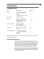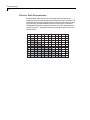
1
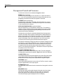
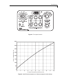
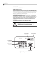
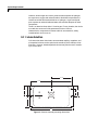
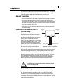
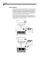
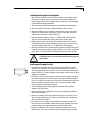
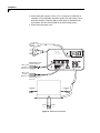
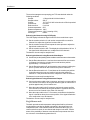
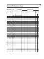
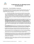
Valco Instruments Co. Inc. Microvolume Thermal Conductivity Detector Instruction Manual tcd2.p65 Rev 4/12 Printed in USA North America, South America, and Australia/Oceania contact: Europe, Asia, and Africa contact: Valco Instruments Co. Inc. VICI AG International 800 · 367 · 8424 sales 713 · 688 · 9345 tech 713 · 688 · 8106 fax [email protected] Schenkon, Switzerland Int + 41 · 41 · 925 · 6200 phone Int + 41 · 41 · 925 · 6201 fax [email protected] This page intentionally left blank for printing purposes Table of Contents Introduction Description and Operating Principle ............................................................... 1 Safety Notes and Information ........................................................................ 2 Components of the Detector System ............................................................. 3 Description of Controls and Connectors ......................................................... 4 System Requirements Components Not Included with the Detector System ..................................... 7 System Purity ................................................................................................ 7 Recommended Carrier Gas Purifiers .............................................................. 7 Carrier Gas Selection ..................................................................................... 7 GC Column Selection ..................................................................................... 8 Installation General Precautions ...................................................................................... 9 Mounting the Detector on the GC ................................................................... 9 Gas Connections .......................................................................................... 10 Column Connection ....................................................................................... 12 Electrical Connections .................................................................................. 13 Initial Power-Up ............................................................................................. 15 Troubleshooting Troubleshooting Chart ................................................................................... 17 Heater Fault Determination ............................................................................ 17 Detector Fault Determination ......................................................................... 18 Maintenance Bake Out Procedure ..................................................................................... 19 Disassembly and Cleaning ............................................................................ 19 Warranty ............................................................................................................. 20 Detector Performance Log ................................................................................... 21 This page intentionally left blank for printing purposes 1 Introduction Description and Operating Principle The Thermal Conductivity Detector (TCD) has been one of the most popular GC detectors since the 1950’s, second perhaps only to the Flame Ionization Detector (FID). The principal of operation is based on the relative change in the thermal conductivity of the gas passing across the detector filament as components elute from the column. Heat is lost continuously by the filament through the carrier gas to the cell wall of the detector. By measuring the amount of current required to maintain a constant filament temperature as gases of varying thermal conductivities cross the filament, a chromatographic signal is produced. This process is nondestructive of the sample and is concentration dependent. The Valco Microvolume TCD is unique in its implementation. Since changes in conductivity are measured only by the change in current required to keep the filament at a constant temperature, each of the two filaments can be operated independently without referencing these changes to a matched filament with reference gas. This constant temperature provides longer filament life and safeguards it from the extremely high temperatures and oxidation which can occur with high concentrations of oxidative or corrosive components. Optional signal referencing is provided to minimize background variables such as column bleed and temperature programming. OUTLET OUTLET FILAMENT A FILAMENT B A FLOW INLET B FLOW INLET Figure 1: Unique dual filament design Cell volume has been minimized to accommodate capillary column chromatography and optimize the sensitivity of the detector at low flow rates. (Carrier flow rates of 1 - 10 mL/min are recommended for best sensitivity.) Thermal stability is maintained in the detector cell to within 0.010°C drift, giving the detector a stable, noise-free signal. The Model TCD2 is a stand-alone system which can be easily added to any chromatograph. It consists of a detector and a control module which incorporates the electrometer and temperature controls. The detector cell includes two separate filaments, capable of independent or referenced (differential) operation. Output signal is provided as 0-1 and 0-10 volt attenuated for chart recorders and 0-1 and 0-10 volts unattenuated for integrators and data systems. Introduction 2 Safety Notes and Information Symbols HOT SURFACE The surface of the detector body may be hot while in operation (possibly in excess of 250°C). Observe caution. ATTENTION Refer to the manual. PROTECTIVE EARTH This internal connection provides protection against electric shock from mains voltages and should not be removed. Installation Category This equipment has been designed for installation category (overvoltage category) II, pollution degree 2. It has been approved for use only in heavy industrial environments and may not be used in the residential, commercial, or light-industrial environment. Safety This instrument has been designed and tested in accordance with the product safety standard, EN61010. It has left the factory in a safe condition. This instruction manual contains important information and warnings which must be followed by the user to insure safe operation and to retain the instrument in a safe condition. The case, chassis, and measuring terminals are connected to the protective earth contact of the mains inlet. The instrument operates with a three-conductor power cord having a protective earthing conductor and a plug with an earthing contact. The mains (line) plug shall only be inserted in a socket outlet provided with a protective earth contact. The protective action must not be negated by the use of an extension cord without a protective conductor. Use only with an approved mains supply cord having a rating of 2A, 250V, or greater. Do not use this equipment in a manner not specified herein. Maintenance The exterior of the instrument should be cleaned regularly with a dusting brush. If necessary, the casing can be cleaned with a moistened cloth (99% water + 1% mild detergent). Spirit or petroleum ether can be used to remove greasy dirt. Any other cleaning agents can attack the plastic and painted surfaces. Under no circumstances should the cleaning fluid get into the instrument. Petroleum ether is flammable, and care should be taken in its use. The detector must be returned to the factory when filament replacement is required. Call VICI Tech Support for return authorization. Introduction 3 Components of the Detector Systems Components of the detector system are listed in Tables 1 and 2. Check the contents of the packages to verify that everything is present. Contact the factory if anything is missing or damaged. (NOTE: damaged shipments must remain with the original packaging for freight company inspection.) Description Quantity Product number Detector cell, Nickel-Iron filament 1 TCD2-NIFED Controller unit with power cord 1 TCD2-C 2 I-24010 1/16' zero dead volume union 2 ZU1C Fused silica adapter for 0.53 mm ID x 0.8 mm OD capillary column 2 FS1R.8 1/16" zero dead volume nut 2 ZN1 1/16" zero dead volume ferrule 2 ZF1 Includes: Cable, output Table 1: Components of the TCD2-NIFE system Description Quantity Product number Detector cell, Tungsten-Rhenium filament 1 TCD2-WRE Controller unit with power cord 1 TCD2-C 2 I-24010 1/16' zero dead volume union 2 ZU1C Fused silica adapter for 0.53 mm ID x 0.8 mm OD capillary column 2 FS1R.8 1/16" zero dead volume nut 2 ZN1 1/16" zero dead volume ferrule 2 ZF1 Includes: Cable, output Table 2: Components of the TCD2-WRE system Specifications Mains (line): 115/230 V~50/60 Hz, 175 VA Fuse: 2 A, time-delay, 5 x 20 mm Pressure: 6.9 kPa (1 psi) operating, 6.9 MPa (1000 psi) max. working Maximum temperature 300°C Heater power: 60 W max., 48 V, PWM Output impedance: 100 Ω Introduction 4 Description of Controls and Connectors Controls and connectors are indicated in Figures 2 and 4. MAINS switch (rear panel) Controls mains (line) voltage to the controller unit. When this switch is on ( | ), the unit is operational except for the detector filaments (see next paragraph) and the detector heater will operate if connected. FILAMENT switch and indicator Controls power to the detector filaments; when the switch is on, current passes through the filaments. The indicator will light even if the detector is not connected to the controller. DETECTOR TEMPERATURE control and indicator Sets the temperature (°C) of the detector heater block. The indicator is steadily on when maximum power is being applied to the heater, steadily off when no power is applied, and regularly blinking on/off when the set temperature has been established. Note that due to the fail-safe mechanism designed into the temperature controller, the heater will not operate if mains power is applied before the heater is connected or if the detector is too cold (< 0°C). If the heater is disconnected with mains on, the unit must first be turned off to restore control of the heater; if the unit is operated in a very cold environment, the detector should first be gently warmed without power applied. The fail-safe mechanism will also act under any condition resulting from loss of control (e.g., over-heating, RTD failure, etc.). If proper procedures have been followed and the controller will not heat the detector, there is cause to suspect that the fail-safe mechanism has been activated. Consult the factory or an authorized representative. Note that the maximum temperature for operation of the TCD2 is 300°C. FILAMENT TEMPERATURE switch Separate 10-turn knobs control Filaments A and B. The value displayed corresponds to temperatures indicated in Figure 3 for nickel/iron filaments. COARSE ZERO control Once filament temperature has been applied, the Coarse Zero knob makes coarse adjustments of the zeroing voltage supplied for establishing the baseline zero on both the strip chart output and the integrator outputs. FINE ZERO control Once coarse adjustments have been made, the Fine Zero control is used to make fine adjustments in the output signals. ATTENUATION control The Attenuation control determines the attenuation of the signal for the chart output. RECORDER switch The Recorder switch selects which signal is directed to the chart output. The choices are A, B, or A - B (or A minus B, which is conventional differential operation with the B channel representing the reference.) The selected output signal is displayed in the LCD display. Introduction 5 Figure 2: Front panel controls 400 350 ACTUAL TEMPERATURE IN °C 300 250 200 150 100 50 0 0 1 2 3 4 5 6 7 8 9 FILAMENT TEMPERATURE KNOB SETTING Figure 3: Actual filament temperature vs. filament temperature knob settings 10 Introduction 6 MAINS POWER connector For connection to 115/230 VAC source. CHART OUTPUT connector Normally connected to a strip chart recorder. This output has an attenuated range of 0-1 volt and 0 - 10 volts, with the signal scaled by the attenuation factor set on the front panel. The output also has an internal signal reference (-) at zero volts. For best noise performance, the shield (earth) and signal reference (-) should not be connected together. UNATTENUATED OUTPUT connector Normally connected to a data acquisition system or other recording means. For convenience, full-scale 0 - 1V and 0 - 10V outputs are provided, with an internal signal reference (-) at zero volts. For best noise performance, the shield (earth) and signal reference (-) should not be connected together. DETECTOR connector For connection to the detector control and heating system. NOTE: These terminals are for connection only to equipment having no accessible live parts. MAINS POWER CONNECTOR Valco Instruments Co. Inc. MAINS MODEL TCD2-C T2.0A 250V 115/230 175VA MAX. UNATTENUATED OUTPUT CONNECTORS MAINS SWITCH OUTPUTS A CHART B A-B DETECTOR CHART OUTPUT CONNECTOR MODEL NO. SERIAL NO. Made in USA by Valco Instruments Co. Inc. DETECTOR CONNECTOR Figure 4: Rear panel connectors 7 System Requirements Components Not Included with the Detector System • Carrier gas (99.999% purity is recommended) • Ultra high purity grade gas pressure regulator with stainless steel diaphragm (recommended) • Any special adapters required for connection to the gas regulator • Flow measuring device • Flow regulating device System Purity Since detection of low concentrations depends in part on the purity of the carrier, the purest carrier available must be used in order to achieve the lowest possible detection limit. To maintain carrier purity, extra care must be taken to assure that the delivery system is clean and free of leaks. Use stainless steel tubing (cleaned to removed manufacturing solvents) instead of nylon or PTFE tubing, which can diffuse contaminants into the carrier. Recommended Carrier Gas Purifiers The Valco Helium Purifer (product number HP2) and Nitrogen Purifer (product number NP2), which utilize a rare earth gettering alloy to effectively remove contaminants, are recommended for ppm level analysis of permanent gases. For other applications, economical and convenient VICI Mat/Sen purifiers are appropriate. Order the P300-1 for nitrogen, P200-1 for hydrogen, or the P100-1 for helium and other inert carrier gases. Carrier Gas Selection The detector’s response to a component is based upon the difference between the thermal conductivities of the component and the carrier gas: the greater the difference, the greater the response. The table below shows thermal conductivities for a variety of light gases. Hydrogen Helium Neon Methane Oxygen Air Nitrogen Carbon monoxide Water Argon Carbon dioxide 45.9 36.9 11.8 8.6 6.6 6.4 6.4 6.2 4.5 4.5 4.2 As an example, note in the table that the thermal conductivity of hydrogen is 46 and helium is 37, while nitrogen is only 6 and argon is even lower at 4. Since the largest difference in thermal conductivity yields the best response, detection of small amounts of hydrogen is better done with argon or nitrogen carrier than with helium. System Requirements 8 However, while nitrogen as a carrier yields excellent response to hydrogen, the response to oxygen and carbon dioxide is diminished compared to the levels that could be achieved with helium or hydrogen. Argon would yield poor response to carbon dioxide and water, but would be adequate for other components. There is no absolute “best choice” of carrier gas. For any situation, the choice must take into account all of the parameters involved: column characteristics, components of interest and their concentrations, safety considerations, carrier cost, etc. GC Column Selection Cell volume has been minimized to accommodate capillary, megabore, and micropacked columns, and to optimize the sensitivity of the detector at low flow rates. However, standard packed columns may also be used if sensitivity is not an issue. 2 13⁄16" 5 5⁄8" 1 1⁄4" 1 1⁄2" 1" 3" 6" Figure 5: Detector assembly mounting dimensions 9 Installation The detector is usually mounted on top of the GC column oven. The power cord for the controller is 1.8 m (6') long; the detector cable and the signal output cables (attenuated and unattenuated) are 1.2 m (4') long. General Precautions • Do not turn the unit on until the carrier gas is flowing through the detector. • Do not shut off or disconnect the carrier gas when the detector is hot, even if the unit is turned off. Turn off the power switch on the back of the controller and allow the detector to cool down naturally before disconnecting or shutting off the carrier gas. • Position the controller unit where the mains switch on the rear panel can be reached easily. Mounting the Detector on the GC Vertical Mounting CHANNEL A VENT The detector has no particular orientation requirements, but it should have adequate thermal isolation from the column oven and injection port. Most GCs have an existing opening which will allow the TCD2 to sit vertically on top of the column oven with the column inlet extending into the oven. If you are replacing an existing detector, you can usually just remove it and set the TCD2 in its place. If not, use a drill or chassis punch to drill a hole of the proper size, and set the detector in position. CHANNEL A INLET (gold ferrule) CHANNEL B VENT CHANNEL B INLET (stainless ferrule) Figure 6: Detector connections While trying to match base plate mounting holes to every GC on the market is impractical, we have located the mounting holes so that at least two of them will coincide with existing holes on the GC. (Refer to Figure 5.) Orient the detector to allow for easy cable and gas connections. The inlet lines installed into the detector must enter the column oven and permit column connection. Temperature loss between the column outlet and the detector should be minimized to prevent possible condensation of the sample. CAUTION: Do not mount the detector near the column oven cool-down vents. Horizontal Mounting Some older GCs have access to the column oven through the side of the GC. This does not present a problem as far as operation of the TCD2 is concerned. Drill a hole at the appropriate location, orient the detector for convenient connection, and mark the position of the mounting holes. Drill the mounting holes and secure the detector to the side of the GC with four sheet metal screws (not supplied). Installation 10 Gas Connections Remember these three points discussed earlier: (1) all surfaces that contact the gas stream must be glass or stainless steel; (2) do not use copper tubing or brass fittings; and (3) all tubes must be thoroughly cleaned and baked before use. The installation instructions below assume that the detector carrier will be supplied from a nearby cylinder. If your installation is different, you may need to modify the instructions appropriately. Consult the VICI catalog or vici.com for any fittings and tubing required. The figures below illustrates gas connections for a typical TCD2 detector system, in referenced and unreferenced modes. Since the distance from the carrier supply to the GC varies from installation to installation, we do not supply tubing to go from that point to the GC. CHANNEL B VENT CHANNEL A VENT DETECTOR CHANNEL A INLET (gold ferrule) CHANNEL B INLET (stainless ferrule) TEE (ZT1) PURIFIER FLOW CONTROLLERS COLUMN INJECTOR CARRIER GAS (99.999% purity) GAS CHROMATOGRAPH Figure 7: Referenced mode (A - B) CHANNEL B VENT CHANNEL A VENT DETECTOR CHANNEL A INLET (gold ferrule) CHANNEL B INLET (stainless ferrule) PURIFIER TEE (ZT1) CARRIER GAS (99.999% purity) FLOW CONTROLLERS COLUMN INJECTOR COLUMN INJECTOR GAS CHROMATOGRAPH Figure 8: Unreferenced mode Installation 11 Installing and Purging the Gas Regulator 1. Make sure the on/off valve on the helium cylinder is completely closed. Screw the CGA fitting nut of the regulator into the helium cylinder. Go beyond finger-tight, but do not tighten the nut all the way – some leakage is required for the purging operation. 2. Turn the output pressure regulating knob completely counterclockwise. 3. Open the cylinder on/off valve slightly and quickly close it again. 4. Adjust the tightness of the regulator connecting nut to allow a pressure reduction of ~690 kPa/sec (100 psi/sec). With a new bottle, the gauge should start out at about 14 MPa (2000 psi). 5. When the pressure drops into the 1.4 - 3.4 MPa (200 - 500 psi) range, open the cylinder on/off valve slightly and quickly close it again. 6. Repeat Step 5 eight or ten times to be certain that all the air is purged. On the final purge, tighten the regulator connecting nut very securely as the pressure approaches the 2.1 - 3.4 MPa (300 - 500 psi) range. 7. Open the cylinder valve to pressurize the regulator once again, then close it and observe the high pressure gauge needle for 15 minutes. If it doesn’t move, there is no critical leak on the high pressure side of the regulator. CAUTION: Never use leak detecting fluids on any part of this system. Installing and Purging a Purifier EZR21 1. If the pressure regulator has a 1/8" male cone-type outlet port, install the Valco 1/8" external to 1/16" internal reducer (EZR21); if it has a 1/4" male cone-type outlet port, install the Valco 1/4" external to 1/16" internal reducer (EZR41). For other regulator outlet fittings, a wide variety of Valco adapters are available. 2. Remove the cap from the inlet tube of the Valco helium purifier and insert the tube fitting into the 1/16" reducer port. (Keep the outlet tube capped.) Use a 1/4" wrench to turn the nut one-quarter turn past the point where the ferrule first starts to grab the tubing. Do not remove the fitting. When made up properly, it should be leak-tight. 3. Turn the output pressure regulating knob clockwise until the gauge registers 345 KPA (50 psi). 4. Allow five minutes for equilibration, then turn the regulating knob all the way counterclockwise. 5. Observe the needle of the output pressure gauge for 15 minutes. There will be a slight initial drop, but if it doesn’t move after that, consider that all the connections are tight. 6. If necessary, use an electronic leak detector to locate any leaks. If a leak detector is not available, tighten all the fittings (including the output pressure guage), and repressurize the system for another test. 7. Upcap the outlet tube of the purifier and purge the system for 15 to 30 minutes at 60 - 80 mL/min to eliminate air from the purifier getter material. Installation 12 Column Connection To prevent detector contamination, we strongly recommend disconnecting the column from the detector during column bakeout procedures. Referenced mode In the referenced mode, the column is connected to the Channel A inlet, and the carrier gas stream is split and used as a reference in channel B. The gas flow rate from both channels must be the same (flow balanced). This mode of operation provides the best baseline stability and the least background noise. Unreferenced mode In the unreferenced mode, Channels A and B are used independently. One column connects to the Channel A inlet, and the other to Channel B. The carrier gas must be the same for both channels. It is also possible to use only one channel with the other capped off, as long as the filament temperature control knob of the unused channel is set to zero. The unreferenced mode has certain limitations: there is a possibility of detector cross-talk (interference) if compound concentrations exceed 1%, and baseline drift and background noise are greater than with the referenced mode. To make column connection as convenient as possible, each TCD is shipped with two Valco 1/16" unions (Product No. ZU1C) complete with nuts and ferrules (Product Nos. ZN1 and ZF1). Also included are two fused silica adapters (FSR1.8) for use with .53 mm ID wide bore capillary columns (.8 mm OD). Refer to the information below to determine the correct Valco fitting for use with other columns. Column Connection Fittings Packed Columns A 1/16" packed column requires only the ZU1C which comes with the TCD. For 1/8" columns, order a ZRU21. ZU1C Used with 1/16" column ZRU21 Used with 1/8" column Installation 13 Packed Columns with Swagelok®-type Female Nut The connection of these columns is similar to that for standard packed columns, but requires a union which adapts the female nut to the Valco fitting. EZU1 Used with 1/16" column EZRU21 Used with 1/8" column Capillary Columns Connection of these columns requires the use of the ZU1C with the appropriate fused silica adapter. For a .53 mm ID x .8 mm OD column, use the FSR1.8 supplied with the TCD. For other sizes, use this table to determine the proper adapter: Column size .32 mm ID x .5 mm OD .25 mm ID x .4 mm OD < .2 mm ID Adapter required FS1R.5 FS1R.4 FS1R.2 ZU1C with fused silica adapter Testing for Leaks It is critical for the system to be leak-tight, and an additional check at this point can save many headaches later on. To test for leaks: 1. Insure that both outlets are capped. 2. Pressurize the entire system with helium to 138 kPa (20 psi). 3. If the system does not hold pressure, check all the fittings with an electronic helium leak detector. DO NOT use leak detecting liquids. Electrical Connections Before connecting the detector cable to the control module, make sure that the control module power cord is unplugged. 1. The heater and filament connections from the detector to the rear panel of the controller are made up in one cable. After making sure that the control module power cord is not plugged in, connect this detector cable to the connector on the control module. The cable connector should be firmly seated by turning the coupling ring clockwise until the detent is felt. For best detector performance, the cable and connector should not be allowed to move while measurements are being made. If the cable is disconnected, exercise care to keep the connecting pins in each connector clean. Installation 14 2. Connect the data output(s). The A / B / A - B outputs are used with an integrator or PC-based data acquisition system; the chart output is for a strip chart recorder. Polarities and full scale range are indicated in the figure below. (Set the recorder/DAQ for the same voltage scale.) 3. Connect the main power cord. Valco Instruments Co. Inc. MAINS MODEL TCD2-C T2.0A 250V 115/230 175VA MAX. 220V OUTPUTS A CHART RED (+10V) BLACK () WHITE (+1V) RED (+10V) BLACK () WHITE (+1V) ATTENUATED STRIP CHART OUTPUT MODEL NO. B SERIAL A-B NO. Valco Instruments Co. Inc. CABLES FOR A, B, and AB CHANNEL A CHANNEL B INLET A INLET B Figure 9: Electrical connections DETECTOR Installation 15 Initial Power-Up Since the TCD is a concentration-dependent detector, the lower the flow rate through the detector, the higher the sensitivity. Column diameter will determine the optimum column flow rate. The microvolume TCD is designed for the lower flow rates typical for capillary columns, and achieves best sensitivity at rates below 10 ml/min. Since the filaments are maintained at constant temperature, the detector can be operated at extremely low flow rates (less than 0.5 ml/min) without damage to the filaments. A - B referenced mode Flow Rate Settings 1. Measure the column flow at the detector’s Channel A out. The optimum flow rate is in the range of 4 - 20 mL/min, with the actual rate dependent on the type of column used. 2. Measure the reference gas flow at Channel B out. It should be as close as possible to the GC column flow. Use a fixed flow restrictor or a good quality flow controller to match the the carrier gas and reference gas flows. 3. Once the flows have been established, make sure the filament switch and the main power switch are in the OFF position, and plug the power cord into an AC main outlet. Initial Conditioning 4. Turn on the control module main power switch and set the detector temperature to 220°C. 5. Turn on the filament power switch and set both filament temperature knobs at 8.0. 6. Condition the detector by allowing it to bake at these settings for at least 12 hours. Temperature Settings 7. After the initial bakeout period, set the detector temperature at 100°C or at the column temperature plus 30°, whichever is higher. 8. Set the filament temperatures at least 50° and as much as 100° higher than the detector temperature. Refer to Figure 3 on page 5, which outlines the relationship between the filament temperature knob settings and the actual filament temperature. Detector sensitivity increases as the temperature differential between the detector and the filaments increases, but filament life decreases as its temperature increases. Thus, the detector temperature should be set as low as possible, determined by the boiling point of the highest boiling component of the sample. 9. Once all temperatures are set, allow plenty of time for the system to equilibrate, evidenced by a stable baseline. Typical equilibration time for going from a cold start-up to 130°C detector temperature is approximately five hours. Detector temperature changes take much longer to equilibrate than do filament temperature changes. Installation 16 The test chromatogram accompanying your TCD was obtained under the following conditions: Sample: ~100 ppm blend in Helium balance Sample volume: 250 µl Column: 10' x 1/16" x 0.040" molecular sieve 5Å micropacked Column flow: 6 mL/min Reference flow: 6 mL/min Column temperature: 65°C Detector temperature: 100°C Filament temperature: 230°C (a setting of 5.0) Carrier gas: Helium Balancing the Channels using LCD Display The LCD display indicates the signal level from the recorder/chart output. 10. Set the recorder switch to A, and use the coarse and fine controls for Channel A to adjust the signal level to about 300 mv. 11. Set the recorder switch to B and repeat the same process to adjust the signal level to about 200 mv. 12. Set the recorder switch to A-B. The display should read about 100 mv. If the signal levels drifts below zero, readjust the A & B channels. The detector is now ready for analytical use. Balancing the Channels using Recorder/Chart Output 10. Use the zero (or shunt) setting on the recorder to set the true zero on the recorder. 11. Set the Recorder switch to A, and use the coarse and fine zero controls for Channel A to bring the recorder pen on scale and to a position approximately 1-2 cm above zero. 12. Set the Recorder switch to B, and repeat the same process, bringing the pen to a position half as far above zero as the pen for Channel A. 13. Set the Recorder switch to A - B, and observe the recorder pen position. It should be above the true zero position, but below the position for Channel A. If the pen drifts below zero, readjust the A and B channels. The detector is now ready for analytical use. Balancing the Channels using Unattenuated Outputs 10. Connect the output cable to the A connector, and use the coarse and fine zero controls for Channel A to bring the baseline signal on scale and to a position approximately 100 mV above zero. 11. Move the output cable to the B connector, and use the coarse and fine zero controls for Channel B to bring the baseline to a position half as far above zero as for Channel A (the value of A minus B). 12. Move the output cable to the A - B connector, and observe the baseline signal. It should be above the true zero position. If the signal drifts below zero, readjust the A and B channels. The detector is now ready for analytical use. Single filament mode The basic procedures and temperature settings described for referenced mode operation can also be applied to operation in the single filament or independent mode. Both channels must have the same carrier gas; you cannot use helium carrier in one channel and nitrogen in the other. Also be aware of the possibility of detector cross-talk when components elute from the columns in concentrations greater than 1%. 17 Troubleshooting Troubleshooting Chart Problem Possible Cause Refer to page: No signal Main or filament power switch off Filament temperature too low Fuse blown Output cable in the wrong connector 4 4 3 14 Signal reversed Signal wires reversed 14 Noisy signal Dirty system or leaking fittings Bad flow controller in system Cell/filament differential too small Filament damaged 7, 13, 19 15 15 2 Cannot zero the signal Recorder/Int. not zeroed Voltage incompatibility Main or filament power switch off 16 14 4 Excessive drift* Block temperature not stabilized Heater fault 15 17 Cell doesn’t heat properly Heater/sensor cable unplugged/ heater fail safe mechanism Heater fault Fuse blown 17 17 3 For technical assistance from Valco Instruments, call (713) 688-9345 or email [email protected]. *Try referenced mode, page 12 Heater Fault Determination The heater control circuit is designed to disable itself in the event of a fault such as over-temperature, shorted heater, short/open temperature sensor, etc. Once disabled, circuit operation is restored by turning off the controller, disconnecting and reconnecting the detector cable, and then turning the controller back on. E.g., if mains power is applied before the detector is connected to the controller, the heater circuit will not operate until mains power is removed, the detector connected, and mains power restored. Under normal circumstances, the amber temperature indicator light will flash once after mains power is applied, before control is established. If the light fails to flash, it indicates that a fault has been detected or (less likely) the heater supply fuse has failed. Troubleshooting 18 Detector Fault Determination Electrical faults in the detector are most easily discovered by making resistance measurements between pins of the detector cable connector. The table below shows the pin numbering and connections for the detector cable (view into pins). Nominal resistance values (in ohms) at 25°C are shown. Unshaded boxed without numbers represent open circuits, and should in no case be blow 1 MΩ. Resistance values given should be within ±10% of the nominal values. Pin 1 2 3 4 5 6 8 9 11 12 13 2 3 4 0 5 25 25 6 8 9 11 12 13 14 0 108 0 25 25 50 19 Maintenance Cleaning the Enclosure The exterior of the instrument should be cleaned regularly with a dusting brush. If necessary, the casing can be cleaned with a moistened cloth (99% water + 1% mild detergent). Spirit or petroleum ether can be used to remove greasy dirt. Any other cleaning agents can attack the plastic and painted surfaces. Under no circumstances should the cleaning fluid get into the instrument. Petroleum ether is flammable, and care should be taken in its use. Bake Out Procedure Under normal conditions, the TCD requires no routine maintenance. However, if the detector is exposed to chemicals which may condense or polymerize within the detector and adversely affect performance, the detector cell can be baked out at elevated temperatures (up to 300°C). Inert carrier gas flow (other than hydrogen, oxygen, or air) should be maintained during the reconditioning procedure. Filament temperature should also be increased to approximate the setpoint of the bake out temperature. If a 24 hour bake out is not sufficient to remove the contamination, the unit must be returned to be factory for disassembly and cleaning. 20 Warranty This Limited Warranty gives the Buyer specific legal rights, and a Buyer may also have other rights that vary from state to state. For a period of 365 calendar days from the date of shipment, Valco Instruments Company, Inc. (hereinafter Seller) warrants the goods to be free from defect in material and workmanship to the original purchaser. During the warranty period, Seller agrees to repair or replace defective and/or nonconforming goods or parts without charge for material or labor, or, at the Seller’s option, demand return of the goods and tender repayment of the price. Buyer’s exclusive remedy is repair or replacement of defective and nonconforming goods, or, at Seller’s option, the repayment of the price. Seller excludes and disclaims any liability for lost profits, personal injury, interruption of service, or for consequential incidental or special damages arising out of, resuiting from, or relating in any manner to these goods This Limited Warranty does not cover defects, damage, or nonconformity resulting from abuse, misuse, neglect, lack of reasonable care, modification, or the attachment of improper devices to the goods. This Limited Warranty does not cover expendable items. This warranty is VOID when repairs are performed by a nonauthorized service center or representative. For information about authorized service centers or representatives, write Customer Repairs, Valco Instruments Company, Inc, P.O. Box 55603, Houston, Texas 77255, or phone (713) 688-9345. At Seller’s option, repairs or replacements will be made on site or at the factory. If repairs or replacements are to be made at the factory, Buyer shall return the goods prepaid and bear all the risks of loss until delivered to the factory. If Seller returns the goods, they will be delivered prepaid and Seller will bear all risks of loss until delivery to Buyer. Buyer and Seller agree that this Limited Warranty shall be governed by and construed in accordance with the laws of the State of Texas. The warranties contained in this agreement are in lieu of all other warranties expressed or implied, including the warranties of merchantability and fitness for a particular purpose. This Limited Warranty supercedes all prior proposals or representations oral or written and constitutes the entire understanding regarding the warranties made by Seller to Buyer. This Limited Warranty may not be expanded or modified except in writing signed by the parties hereto. 21 Detector Performance Log Detector Model: Date TCD2 Operator Serial Number: Comments Date of purchase: Filament Detector Noise temp temp level (°C) (°C) Initial power-up (IPU) — IPU, detector to analysis temp — — Ambient — IPU, column installed IPU, column to analysis temp 100 Sample — — Detector flow A B