1
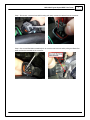
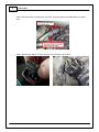
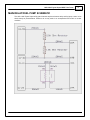
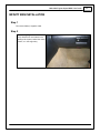
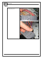
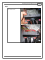
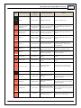
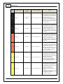
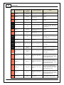
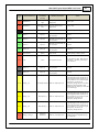
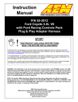
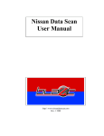
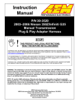
Manual Transmission
Plug & Play Adapter Harness
Instruction
Manual
2
P/N 30-3500
OVERVIEW
The 30-3500 AEM Infinity Adapter Kit is designed for the 1993–1998 Toyota Supra MKIV Twin Turbo
(manual transmission). This is a true standalone system that eliminates the use of the factory ECU. The
use of this adapter makes the kit “plug and play” so no cutting or splicing wires is necessary. The base
configuration files available for the Infinity EMS are starting points only and will need to be modified for
every specific application.
The available AEM Infinity EMS part numbers for this adapter kit are:
30-7100 INFINITY-8
30-7101 INFINITY-10
GETTING STARTED
Refer to the 10-7100 for EMS 30-7100 Infinity Quick Start Guide for additional information on getting
the engine started with the Infinity EMS. Toyota Supra MKIV Twin Turbo base sessions are located in C:
\Documents\AEM\Infinity Tuner\Sessions\Base Sessions
Downloadable files for 1993–1998 MKIV Toyota Supra Twin Turbo
7100-XXXX-62 Infinity-10 (XXXX = serial number)
7101-XXXX-63 Infinity-8 (XXXX = serial number)
OPTIONS
30-3600 UEGO Wideband O2 Sensor Extension Harness
Extension harness to connect AEM UEGO Wideband O2 sensor to 6-pin Deutsch
30-3601 IP67 Comms Cable
30-3602 IP67 Logging Cable
USB A-to-A extension cable: 39” long with right angled connector and bayonet style lock
© 2015 AEM Performance Electronics
1993–1998 Toyota Supra MKIV Twin Turbo
3
INFINITY CONNECTORS
The AEM Infinity EMS uses the MX123 Sealed Connection System
from Molex. AEM strongly recommends that users become familiar
with the proper tools and procedures for working with these high
density connectors before attempting any modifications. The entire
Molex MX123 User Manual can be downloaded direct from Molex at:
INFINITY ADAPTER HARNESS
Included with the 1993–1998 Toyota Supra MKIV Twin Turbo kit is an adapter harness. This is used to
make the connection between the AEM Infinity EMS and the Toyota wiring harness plug and play. This
is depicted below with the 73-pin and 56-pin connectors and the Toyota header. There are also a few
other integrated connectors.
© 2015 AEM Performance Electronics
4
P/N 30-3500
ECU SETUP WIZARD
Important Application Specific Settings
Engine
In the Wizard Engine tab confirm the following:
Number of Cylinders
Engine Cycle Type
Ignition Type
Firing Order
=
=
=
=
6
4 Stroke
Sequential (Coil On Plug)
1-5-3-6-2-4
© 2015 AEM Performance Electronics
1993–1998 Toyota Supra MKIV Twin Turbo
5
Cam/Crank
In the Wizard Cam/Crank tab confirm the following:
Toyota Supra (1993–1998 Turbo)
Open the Advanced Setup tab and set the following:
Crank Noise Cancellation
Cam 1 Noise Cancellation
= 70
= 70
Add the 1-Axis Lookup Table VR_PwmDuty [%] to your layout. Set the following:
Ignition Sync
Add a text grid control to your layout and select the following channels. Make sure their values match
the settings below for initial timing sync.
TrigOffset [degBTDC]
CamSyncAdjustment
= 23.00
= 11.00
See QuickStart Guide section Setup: Ignition Sync for instructions on timing sync.
Idle Stepper Max Steps
Go to Setup Wizard Idle page and confirm the following:
Idle Stepper Max Steps = 132
AC Input Switch
Go to Setup Wizard Input Function Assignment page and confirm the following:
AC Input Switch Setup = Analog17[V]
© 2015 AEM Performance Electronics
6
P/N 30-3500
IDLE AIR CONTROL VALVE REQUIREMENTS
Many Toyota, Mitsubishi, and other vehicles use an Idle Air Control Valve with a Unipolar Stepper Motor
(6-pin connector) and MUST be modified. See instructions below. A Bipolar Stepper Motor (e.g., GM)
will have a 4-pin connector and DOES NOT need to be modified.
*This info does not apply to vehicles that utilize IACV solenoids.
The 2 center pins (Black-Red wires) supply 12V power to the stepper motor in the factory setup,
however these pins MUST BE DISCONNECTED before powering the AEM Infinity ECU.
© 2015 AEM Performance Electronics
1993–1998 Toyota Supra MKIV Twin Turbo
7
Step 1: Disconnect connector from IACV housing and gently remove the retainer from the connector.
Step 2: Use a small flat-blade screwdriver/pick to move the terminal locks while pulling the Black-Red
wires out from the backside of the connector.
© 2015 AEM Performance Electronics
8
P/N 30-3500
Step 3: Use heat shrink to insulate both 12V wires, and then zip-tie the insulated wires to a nearby
loom.
Step 4: Reinstall the retainer, and then plug the connector back into the IACV.
© 2015 AEM Performance Electronics
1993–1998 Toyota Supra MKIV Twin Turbo
9
MAIN RELAY/FUEL PUMP SCHEMATIC
The 1993–1998 Toyota Supra Infinity patch harness requires a harness relay and fuel pump control to be
wired exactly as pictured below. Failure to do so may result in an unresponsive ECU and/or a no-start
condition.
© 2015 AEM Performance Electronics
10
P/N 30-3500
ECU COVER MODIFICATIONS
It is recommend that the OEM ECU cover panel be modified and reinstalled with the AEM Infinity EMS
when utilizing the mounting bracket. Failure to properly clearance and reinstall this panel (Toyota
PN#55199-14020) could potentially result in damage to the ECU, adapter harness, ECU connectors and/
or USB cables and connectors.
Please note clearance modifications below. These modifications should be performed with a die grinder,
90-degree sander, or plastic shears.
Step 1: Remove the four ribs located near the center of the cover as highlighted below.
Step 2: Trim the center support leg as outlined. Test fit, note, and trim any additional areas required.
© 2015 AEM Performance Electronics
1993–1998 Toyota Supra MKIV Twin Turbo
INFINITY EMS INSTALLATION
Step 1
Disconnect battery's negative cable.
Step 2
Locate factory Engine Control Unit
(ECU). Most ECU's are located in the
passenger kick panel, behind the center
console, or in the engine bay.
© 2015 AEM Performance Electronics
11
P/N 30-3500
12
Step 3
Unplug factory harness plugs at ECU
and remove factory ECU.
© 2015 AEM Performance Electronics
1993–1998 Toyota Supra MKIV Twin Turbo
Step 4
Plug factory harness plugs into AEM
Infinity Adapter Harness.
© 2015 AEM Performance Electronics
13
P/N 30-3500
14
Step 5
Mount the Infinity ECU and
connect Infinity connectors and
USB cables.
Step 6
Run the USB cables to an easily accessible location.
Step 7
Reconnect the battery's negative cable.
© 2015 AEM Performance Electronics
1993–1998 Toyota Supra MKIV Twin Turbo
15
PINOUTS
Infinity Pinouts
Infinity
Pin
C1-1
Dedicated
Dedicated and not reconfigurable
Assigned
Assigned but reconfigurable
Available
Available for user setup
Not Applicable
Not used in this configuration
Required
Required for proper function
Hardware Reference
LowsideSwitch_4
7100-XXXX-62
7101-XXXX-63
Function
A/C Relay Control
Hardware Specification
Lowside switch, 4A max, NO
internal f ly back diode.
See "LowSide Assignment Tables" f or
output assignment.
See Setup Wizard Page "LowSide
Assignment Tables" f or output assignment
and 2D table "LS5_Duty [%]" f or
activ ation.
See Setup Wizard Page "LowSide
Assignment Tables" f or output assignment
and 2D table "LS6_Duty [%]" f or
activ ation.
C1-2
LowsideSwitch_5
LS5
Lowside switch, 4A max with
internal f ly back diode. Inductiv e
load should NOT hav e f ull time
power.
C1-3
LowsideSwitch_6
LS6
Lowside switch, 4A max with
internal f ly back diode. Inductiv e
load should NOT hav e f ull time
power.
C1-4
UEGO 1 Heat
C1-5
UEGO 1 IA
Notes
Lowside switch f or UEGO heater control.
Connect to pin 4 of Bosch UEGO sensor.
NOTE that pin 3 of the Sensor is heater (+)
and must be power by a f used/switched
12V supply .
UEGO 1 Heat
Trim Current signal. Connect to pin 2 of
Bosch UEGO sensor.
UEGO 1 IA
Bosch UEGO controller
C1-6
UEGO 1 IP
UEGO 1 IP
Pumping Current signal. Connect to pin 6
of Bosch UEGO sensor.
C1-7
UEGO 1 UN
UEGO 1 UN
Nernst Voltage signal. Connect to pin 1 of
Bosch UEGO sensor.
C1-8
UEGO 1 VM
UEGO 1 VM
Virtual Ground signal. Connect to pin 5 of
Bosch UEGO sensor.
Flash Enable
Not usually needed f or automatic f irmware
updates through Inf inity Tuner. If
connection errors occur during update,
connect 12 v olts to this pin bef ore
proceeding with upgrade. Disconnect the
12 v olts signal af ter the update.
C1-9
Flash_Enable
© 2015 AEM Performance Electronics
10K pulldown
16
P/N 30-3500
Infinity
Pin
Hardware Reference
C1-10
+12V_R8C_CPU
C1-11
Coil 4
C1-12
Coil 3
7100-XXXX-62
7101-XXXX-63
Function
Hardware Specification
Notes
Dedicated power management
CPU
Full time battery power. MUST be powered
bef ore the ignition switch input is triggered.
(See C1-65.)
Coil 4
25 mA max source current
0–5V Falling edge f ire. DO NOT connect
directly to coil primary . Must use an ignitor
OR CDI that accepts a FALLING edge f ire
signal.
Coil 3
25 mA max source current
0–5V Falling edge f ire. DO NOT connect
directly to coil primary . Must use an ignitor
OR CDI that accepts a FALLING edge f ire
signal.
Battery Perm Power
C1-13
Coil 2
Coil 2
25 mA max source current
0–5V Falling edge f ire. DO NOT connect
directly to coil primary . Must use an ignitor
OR CDI that accepts a FALLING edge f ire
signal.
C1-14
Coil 1
Coil 1
25 mA max source current
0–5V Falling edge f ire. DO NOT connect
directly to coil primary . Must use an ignitor
OR CDI that accepts a FALLING edge f ire
signal.
C1-15
Coil 6
Coil 6
25 mA max source current
0–5V Falling edge f ire. DO NOT connect
directly to coil primary . Must use an ignitor
OR CDI that accepts a FALLING edge f ire
signal.
C1-16
Coil 5
Coil 5
25 mA max source current
0–5V Falling edge f ire. DO NOT connect
directly to coil primary . Must use an ignitor
OR CDI that accepts a FALLING edge f ire
signal.
C1-17
LowsideSwitch_2
Lowside switch, 4A max, NO
internal f ly back diode.
See "LowSide Assignment Tables" f or
output assignment.
Lowside switch, 4A max with
internal f ly back diode. Inductiv e
load should NOT hav e f ull time
power.
See Wizard page "LowSide Assignment
Tables" f or output assignment.
MIL Activ ates when any of the f ollowing
f lags are true: ErrorAirTemp, ErrorBaro,
ErrorCoolantTemp, ErrorEBP,
ErrorFuelPressure, UEGO_0_Diag_error,
UEGO_1_Diag_error, ErrorMAFAnalog,
ErrorMAFDigital, ErrorMAP,
ErrorOilPressure, ErrorThrottle.
Dedicated analog ground
Analog 0–5V sensor ground
C1-18
LowsideSwitch_3
C1-19
AGND_1
Coolant Fan 1
Control
MIL Output
Sensor Ground
© 2015 AEM Performance Electronics
1993–1998 Toyota Supra MKIV Twin Turbo
Infinity
Pin
Hardware Reference
C1-20
AGND_1
C1-21
Crankshaf t Position
Sensor Hall
C1-22
7100-XXXX-62
7101-XXXX-63
Function
Notes
Dedicated analog ground
Analog 0–5V sensor ground
Crankshaf t Position
Sensor Hall
10K pullup to 12V. Will work with
ground or f loating switches.
See Setup Wizard page Cam/Crank f or
options.
Camshaf t Position
Sensor 1 Hall
Camshaf t Position
Sensor 1 Hall
10K pullup to 12V. Will work with
ground or f loating switches.
See Setup Wizard page Cam/Crank f or
options.
C1-23
Digital_In_2
Camshaf t Position
Sensor 2 Hall
10K pullup to 12V. Will work with
ground or f loating switches.
See Setup Wizard page Cam/Crank f or
options.
C1-24
Digital_In_3
Turbo Speed Hz
10K pullup to 12V. Will work with
ground or f loating switches.
See Setup Wizard page Input Function
Assignment f or calibration constant.
TurboSpeed [RPM] = Turbo [Hz] * Turbo
Speed Calibration.
C1-25
Digital_In_4
Vehicle Speed Sensor
10K pullup to 12V. Will work with
ground or f loating switches.
See Setup Wizard page Input Function
Assignment f or calibration constant.
C1-26
Digital_In_5
Flex Fuel
10K pullup to 12V. Will work with
ground or f loating switches.
See channel FlexDigitalIn [Hz] f or raw
f requency input data.
C1-27
Knock Sensor 1
Knock Sensor 1
Dedicated knock signal
processor
See Setup Wizard page Knock Setup f or
options.
C1-28
Knock Sensor 2
Knock Sensor 2
Dedicated knock signal
processor
See Setup Wizard page Knock Setup f or
options.
C1-29
+12V_Relay _Control
0.7A max ground sink f or
external relay control
Will activ ate at key on and at key of f
according to the conf iguration settings.
C1-30
Power Ground
Power Ground
Connect directly to battery ground.
C1-31
CANL_Aout
AEMNet CANL
Dedicated High Speed CAN
Transceiv er
Recommend twisted pair (one twist per 2")
with terminating resistor. Contact AEM f or
additional inf ormation.
C1-32
CANH_Aout
AEMNet CANH
Dedicated High Speed CAN
Transceiv er
Recommend twisted pair (one twist per 2")
with terminating resistor. Contact AEM f or
additional inf ormation.
C1-33
LowsideSwitch_1
Lowside switch, 4A max with
internal f ly back diode. Inductiv e
load should NOT hav e f ull time
power.
See Setup Wizard page Boost Control f or
options. Monitor BoostControl [%] channel
f or output state.
C1-34
Lowside Fuel Pump driv e
Lowside switch, 4A max, NO
internal f ly back diode.
Switched ground. Will prime f or 2 seconds
at key on and activ ate if RPM > 0.
© 2015 AEM Performance Electronics
Sensor Ground
Hardware Specification
17
+12V Relay Control
Ground
Boost Control
Fuel Pump
18
P/N 30-3500
Infinity
Pin
C1-35
C1-36
C1-37
C1-38
C1-39
C1-40
Hardware Reference
Analog_In_7
Analog_In_8
Analog_In_9
Analog_In_10
Analog_In_11
Analog_In_12
7100-XXXX-62
7101-XXXX-63
Function
Throttle Position
Sensor
MAP Sensor
Fuel Pressure
Baro Sensor
Shif t Switch Input
Mode Switch
Hardware Specification
Notes
12 bit A/D, 100K pullup to 5V
0–5V analog signal. Use +5V Out pins as
power supply and Sensor Ground pins as
the low ref erence. Do not connect signals
ref erenced to +12V as this can
permanently damage the ECU. See the
Setup Wizard Set Throttle Range page f or
automatic min/max calibration. Monitor the
Throttle [%] channel. Also DB1_TPSA [%]
f or DBW applications.
12 bit A/D, 100K pullup to 5V
0–5V analog signal. Use +5V Out pins as
power supply and Sensor Ground pins as
the low ref erence. Do not connect signals
ref erenced to +12V as this can
permanently damage the ECU. See the
Setup Wizard Set Manif old Pressure page
f or setup and calibration. Monitor the MAP
[kPa] channel.
12 bit A/D, 100K pullup to 5V
0–5V analog signal. Use +5V Out pins as
power supply and Sensor Ground pins as
the low ref erence. Do not connect signals
ref erenced to +12V as this can
permanently damage the ECU. See the
Setup Wizard Fuel Pressure page f or setup
and calibration. Monitor the FuelPressure
[psig] channel.
12 bit A/D, 100K pullup to 5V
0–5V analog signal. Use +5V Out pins as
power supply and Sensor Ground pins as
the low ref erence. Do not connect signals
ref erenced to +12V as this can
permanently damage the ECU. See the
Setup Wizard Barometric Pressure page
f or setup and calibration. Monitor the
BaroPress [kPa] channel.
12 bit A/D, 100K pullup to 5V
0–5V analog signal. Use +5V Out pins as
power supply and Sensor Ground pins as
the low ref erence. Do not connect signals
ref erenced to +12V as this can
permanently damage the ECU.
See the 1D lookup table 'Shif tSwitch' f or
setup. Also assignable to multiple
f unctions. See Setup Wizard f or details.
12 bit A/D, 100K pullup to 5V
0–5V analog signal. Use +5V Out pins as
power supply and Sensor Ground pins as
the low ref erence. Do not connect signals
ref erenced to +12V as this can
permanently damage the ECU.
See the 1D lookup table 'ModeSwitch' f or
input state.
A multi-position rotary switch such as AEM
P/N 30-2056 is recommended.
Also assignable to multiple f unctions. See
Setup Wizard f or details.
© 2015 AEM Performance Electronics
1993–1998 Toyota Supra MKIV Twin Turbo
Infinity
Pin
Hardware Reference
7100-XXXX-62
7101-XXXX-63
Function
Hardware Specification
19
Notes
C1-41
+5V_Out_1
+5V Out
Regulated, f used +5V supply f or
sensor power
Analog sensor power
C1-42
+5V_Out_1
+5V Out
Regulated, f used +5V supply f or
sensor power
Analog sensor power
C1-43
HighsideSwitch_1
HS1 (switched 12V)
0.7A max, High Side Solid State
Relay
See Setup Wizard page 'HighSide
Assigment Tables' f or conf iguration
options. See 2D lookup table 'HS1_Table'
f or activ ation settings.
0.7A max, High Side Solid State
Relay
See Setup Wizard page 'HighSide
Assigment Tables' f or conf iguration
options. See 2D lookup table 'HS0_Table'
f or activ ation settings.
See Setup Wizard page 'VTEC' f or def ault
activ ation criteria.
C1-44
HighsideSwitch_0
C1-45
Crankshaf t Position
Sensor VR+
VTEC
Crankshaf t Position
Sensor VR+
See Setup Wizard page Cam/Crank f or
options.
Dif f erential Variable Reluctance
Zero Cross Detection
C1-46
Crankshaf t Position
Sensor VR-
Crankshaf t Position
Sensor VR-
See Setup Wizard page Cam/Crank f or
options.
C1-47
Camshaf t Position
Sensor 1 VR-
Camshaf t Position
Sensor 1 VR-
See Setup Wizard page Cam/Crank f or
options.
Dif f erential Variable Reluctance
Zero Cross Detection
C1-48
Camshaf t Position
Sensor 1 VR+
C1-49
VR+_In_2
Camshaf t Position
Sensor 1 VR+
Non Driv en Lef t
Wheel Speed Sensor
+
C1-50
VR-_In_2
Non Driv en Lef t
Wheel Speed Sensor
-
C1-51
VR-_In_3
Driv en Lef t Wheel
Speed Sensor -
See Setup Wizard page Cam/Crank f or
options.
Dif f erential Variable Reluctance
Zero Cross Detection
Dif f erential Variable Reluctance
Zero Cross Detection
See Non Driv en Wheel Speed Calibration
in the Setup Wizard Input Function
Assignment page.
See Driv en Wheel Speed Calibration in the
Setup Wizard Input Function Assignment
page.
C1-52
VR+_In_3
Driv en Lef t Wheel
Speed Sensor +
C1-53
DBW1 Motor -
DBW Motor Control
Close
5.0A max Throttle Control
Hbridge Driv e
+12V to close
C1-54
DBW1 Motor +
DBW Motor Control
Open
5.0A max Throttle Control
Hbridge Driv e
+12V to open
C1-55
Power Ground
Ground
Power Ground
Connect directly to battery ground.
C1-56
Injector 6
Saturated or peak and hold, 3A
max continuous
Injector 6
© 2015 AEM Performance Electronics
Injector 6
20
P/N 30-3500
Infinity
Pin
Hardware Reference
7100-XXXX-62
7101-XXXX-63
Function
Hardware Specification
Notes
C1-57
Injector 5
Injector 5
Saturated or peak and hold, 3A
max continuous
Injector 5
C1-58
Injector 4
Injector 4
Saturated or peak and hold, 3A
max continuous
Injector 4
C1-59
Injector 3
Injector 3
Saturated or peak and hold, 3A
max continuous
Injector 3
C1-60
Power Ground
Ground
Power Ground
Connect directly to battery ground.
C1-61
+12V
+12V In
12 v olt power f rom relay
12 v olt power f rom relay . Relay must be
controlled by +12V Relay Control signal,
pin C1-29 abov e.
C1-62
Injector 2
Injector 2
Saturated or peak and hold, 3A
max continuous
Injector 2
C1-63
Injector 1
Injector 1
Saturated or peak and hold, 3A
max continuous
Injector 1
C1-64
+12V
12 v olt power f rom relay
12 v olt power f rom relay . Relay must be
controlled by +12V Relay Control signal
pin C1-29 abov e.
C1-65
+12V_SW
10K pulldown
Full time battery power must be av ailable
at C1-10 bef ore this input is triggered.
C1-66
Analog_In_Temp_1
Coolant Temp Sensor
12 bit A/D, 2.49K pullup to 5V
See "Coolant Temperature" Setup Wizard
f or selection.
C1-67
Analog_In_Temp_2
Intake Air
Temperature
12 bit A/D, 2.49K pullup to 5V
See "Air Temperature" Setup Wizard f or
selection.
C1-68
Harness_Analog_In_Tem
p_3
Oil Temperature
Sensor
12 bit A/D, 2.49K pullup to 5V
See 1D table OilTempCal table f or
calibration data and OilTemp [C] f or
channel data.
C1-69
Stepper_2A
Stepper 2A
Automotiv e, Programmable
Stepper Driv er, up to 28V and
±1.4A
Be sure that each internal coil of the
stepper motor is properly paired with the
1A/1B and 2A/2B ECU outputs. Supports
Bi-Polar stepper motors only .
C1-70
Stepper_1A
Stepper 1A
Automotiv e, Programmable
Stepper Driv er, up to 28V and
±1.4A
Be sure that each internal coil of the
stepper motor is properly paired with the
1A/1B and 2A/2B ECU outputs. Supports
Bi-Polar stepper motors only .
Be sure that each internal coil of the
stepper motor is properly paired with the
1A/1B and 2A/2B ECU outputs. Supports
Bi-Polar stepper motors only .
+12V In
Ignition Switch
C1-71
Stepper_2B
Stepper 2B
Automotiv e, Programmable
Stepper Driv er, up to 28V and
±1.4A
C1-72
Stepper_1B
Stepper 1B
Automotiv e, Programmable
Stepper Driv er, up to 28V and
±1.4A
Be sure that each internal coil of the
stepper motor is properly paired with the
1A/1B and 2A/2B ECU outputs. Supports
Bi-Polar stepper motors only .
C1-73
Power Ground
Power Ground
Connect directly to battery ground.
Ground
© 2015 AEM Performance Electronics
1993–1998 Toyota Supra MKIV Twin Turbo
Infinity
Pin
Hardware Reference
7100-XXXX-62
7101-XXXX-63
Function
Hardware Specification
21
Notes
C2-1
DBW2 Motor +
DBW Motor Control
Open
5.0A max Throttle Control
Hbridge Driv e
+12V to open
C2-2
DBW2 Motor -
DBW Motor Control
Close
5.0A max Throttle Control
Hbridge Driv e
+12V to close
C2-3
Power Ground
Ground
Power Ground
Connect directly to battery ground.
C2-4
Injector 7
Injector 7
Saturated or peak and hold, 3A
max continuous
Injector 7
C2-5
Injector 8
Injector 8
Saturated or peak and hold, 3A
max continuous
Injector 8
C2-6
Injector 9
Injector 9
Saturated or peak and hold, 3A
max continuous
Injector 9
C2-7
Injector 10
Injector 10
Saturated or peak and hold, 3A
max continuous
Injector 10
C2-8
Power Ground
Ground
Power Ground
Connect directly to battery ground.
C2-9
+12V
+12V In
12 v olt power f rom relay
12 v olt power f rom relay . Relay must be
controlled by +12V Relay Control signal,
pin C1-29 abov e.
C2-10
Injector 11
Injector 11
Saturated or peak and hold, 3A
max continuous
Not used
C2-11
Injector 12
Injector 12
Saturated or peak and hold, 3A
max continuous
Not used
12 bit A/D, 100K pullup to 5V
0–5V analog signal. Use +5V Out pins as
power supply and Sensor Ground pins as
the low ref erence. Do not connect signals
ref erenced to +12V as this can
permanently damage the ECU. See Setup
Wizard Input Functions page f or input
selection. See AC_Request_In 1-axis table
f or activ ation logic.
12 bit A/D, 100K pullup to 5V
0–5V analog signal. Use +5V Out pins as
power supply and Sensor Ground pins as
the low ref erence. Do not connect signals
ref erenced to +12V as this can
permanently damage the ECU.
DBW_APP2 [%]
12 bit A/D, 100K pullup to 5V
0–5V analog signal. Use +5V Out pins as
power supply and Sensor Ground pins as
the low ref erence. Do not connect signals
ref erenced to +12V as this can
permanently damage the ECU.
Charge Out
Temperature
12 bit A/D, 2.49K pullup to 5V
See ChargeOutTemp [C] table f or
calibration data and ChargeOutTemp [C]
f or channel data.
C2-12
C2-13
Analog_In_17
Analog_In_18
C2-14
Analog_In_19
C2-15
Analog_In_Temp_4
© 2015 AEM Performance Electronics
A/C Analog Request
DBW_APP1 [%]
22
P/N 30-3500
Infinity
Pin
Hardware Reference
7100-XXXX-62
7101-XXXX-63
Function
Hardware Specification
Notes
C2-16
Analog_In_Temp_5
Airbox Temperature
12 bit A/D, 2.49K pullup to 5V
See AirboxTemp [C] table f or calibration
data and AirboxTemp [C] f or channel data.
C2-17
Analog_In_Temp_6
Fuel Temperature
12 bit A/D, 2.49K pullup to 5V
See FuelTemp [C] table f or calibration data
and FuelTemp [C] f or channel data.
12 bit A/D, 100K pullup to 5V
0–5V analog signal. Use +5V Out pins as
power supply and Sensor Ground pins as
the low ref erence. Do not connect signals
ref erenced to +12V as this can
permanently damage the ECU. See Setup
Wizard Oil Pressure page f or setup
options. See OilPressure [psig] f or channel
data.
C2-18
C2-19
C2-20
Analog_In_13
Analog_In_14
Analog_In_15
Oil Pressure
Traction Control Mode
12 bit A/D, 100K pullup to 5V
/ Sensitiv ity
Exhaust Back
Pressure
DBW1_TPSB [%]
0–5V analog signal. Use +5V Out pins as
power supply and Sensor Ground pins as
the low ref erence. Do not connect signals
ref erenced to +12V as this can
permanently damage the ECU. See the
TC_SlipTrgtTrim [MPH] 1-axis table. A
multi-position rotary switch such as AEM
P/N 30-2056 is recommended.
12 bit A/D, 100K pullup to 5V
0–5V analog signal. Use +5V Out pins as
power supply and Sensor Ground pins as
the low ref erence. Do not connect signals
ref erenced to +12V as this can
permanently damage the ECU. See Setup
Wizard Exhaust Pressure page f or setup
options. See EBPress [kPa] f or channel
data.
12 bit A/D, 100K pullup to 5V
0–5V analog signal. Use +5V Out pins as
power supply and Sensor Ground pins as
the low ref erence. Do not connect signals
ref erenced to +12V as this can
permanently damage the ECU.
C2-21
Analog_In_16
C2-22
+5V_Out_2
+5V Out
Regulated, f used +5V supply f or
sensor power
Analog sensor power
C2-23
+5V_Out_2
+5V Out
Regulated, f used +5V supply f or
sensor power
Analog sensor power
C2-24
+5V_Out_2
+5V Out
Regulated, f used +5V supply f or
sensor power
Analog sensor power
C2-25
VR+_In_5
Driv en Right Wheel
Speed Sensor +
C2-26
VR-_In_5
Driv en Right Wheel
Speed Sensor -
C2-27
VR-_In_4
Non Driv en Right
Wheel Speed Sensor
-
C2-28
V R+_In_4
Dif f erential Variable Reluctance
Zero Cross Detection
Dif f erential Variable Reluctance
Zero Cross Detection
See Driv en Wheel Speed Calibration in the
Setup Wizard Input Function Assignment
page.
See Non Driv en Wheel Speed Calibration
in the Setup Wizard Input Function
Assignment page.
Non Driv en Right
Wheel Speed Sensor
+
© 2015 AEM Performance Electronics
1993–1998 Toyota Supra MKIV Twin Turbo
Infinity
Pin
Hardware Reference
7100-XXXX-62
7101-XXXX-63
Function
Hardware Specification
Tachometer
Lowside switch, 4A max with
internal f ly back diode, 2.2K 12V
pullup. Inductiv e load should
NOT hav e f ull time power.
See Setup Wizard page Tacho f or
conf iguration options.
23
Notes
C2-29
LowsideSwitch_9
C2-30
AGND_2
Sensor Ground
Dedicated analog ground
Analog 0–5V sensor ground
C2-31
AGND_2
Sensor Ground
Dedicated analog ground
Analog 0–5V sensor ground
C2-32
AGND_2
Sensor Ground
Dedicated analog ground
Analog 0–5V sensor ground
12 bit A/D, 100K pullup to 5V
0–5V analog signal. Use +5V Out pins as
power supply and Sensor Ground pins as
the low ref erence. Do not connect signals
ref erenced to +12V as this can
permanently damage the ECU.
12 bit A/D, 100K pullup to 5V
0–5V analog signal. Use +5V Out pins as
power supply and Sensor Ground pins as
the low ref erence. Do not connect signals
ref erenced to +12V as this can
permanently damage the ECU. See
3StepSwitch 1-axis table f or setup.
12 bit A/D, 100K pullup to 5V
0–5V analog signal. Use +5V Out pins as
power supply and Sensor Ground pins as
the low ref erence. Do not connect signals
ref erenced to +12V as this can
permanently damage the ECU. See
USBLoggingRequestIn channel f or input
state. See Setup Wizard page USB
Logging f or conf iguration options.
Charge Out Pressure
12 bit A/D, 100K pullup to 5V
0–5V analog signal. Use +5V Out pins as
power supply and Sensor Ground pins as
the low ref erence. Do not connect signals
ref erenced to +12V as this can
permanently damage the ECU. See
ChargeOutPress [kPa] channel f or input
state. See Setup Wizard page Charge Out
Pressure f or calibration options.
Spare Digital Input
No pullup. Will work with TTL
signals.
Input can be assigned to dif f erent pins.
See Setup Wizard page Input Function
Assignments f or input mapping options.
Clutch Switch
No pullup. Will work with TTL
signals.
See ClutchSwitch 1-axis table f or setup
options. Input can be assigned to dif f erent
pins. See Setup Wizard page Input
Function Assignments f or input mapping
options.
C2-33
C2-34
C2-35
Analog_In_20
Analog_In_21
Analog_In_22
C2-36
Analog_In_23
C2-37
Digital_In_6
C2-38
Digital_In_7
© 2015 AEM Performance Electronics
Spare Analog Input
3 Step Enable Switch
USB Logging
Activ ate
24
P/N 30-3500
Infinity
Pin
Hardware Reference
7100-XXXX-62
7101-XXXX-63
Function
Hardware Specification
Notes
C2-39
Power Ground
Ground
Power Ground
Connect directly to battery ground.
C2-40
Power Ground
Ground
Power Ground
Connect directly to battery ground.
C2-41
CanH_Bout
CANH
Dedicated High Speed CAN
Transceiv er
Not used
C2-42
CanL_Bout
CANL
Dedicated High Speed CAN
Transceiv er
Not used
Activ ates if any of the f ollowing f lags are
true: OilPressProtectOut, LeanProtectOut,
CoolantProtect. Output can be assigned to
other f unctions. See Setup Wizard page
LowSide Assignment Tables f or additional
options.
See Spare GPO1 Basic Setup section of
User GPIOs and PWM Setup Wizard page
LowSide Assignment Tables f or additional
options.
C2-43
LowsideSwitch_8
Engine Protect
Warning Out
Lowside switch, 4A max with
internal f ly back diode. Inductiv e
load should NOT hav e f ull time
power.
C2-44
LowsideSwitch_7
Spare GPO1
Lowside switch, 4A max with
internal f ly back diode. Inductiv e
load should NOT hav e f ull time
power.
C2-45
UEGO 2 VM
UEGO 2 VM
Virtual Ground signal. Connect to pin 5 of
Bosch UEGO sensor.
C2-46
UEGO 2 UN
UEGO 2 UN
Nernst Voltage signal. Connect to pin 1 of
Bosch UEGO sensor.
C2-47
UEGO 2 IP
UEGO 2 IP
Pumping Current signal. Connect to pin 6
of Bosch UEGO sensor.
C2-48
UEGO 2 IA
UEGO 2 IA
Bosch UEGO Controller
C2-49
UEGO 2 HEAT
C2-50
+12V_R8C_CPU
C2-51
C2-52
Coil 7
Coil 8
Trim Current signal. Connect to pin 2 of
Bosch UEGO sensor.
Lowside switch f or UEGO heater control.
Connect to pin 4 of Bosch UEGO sensor.
NOTE that pin 3 of the Sensor is heater (+)
and must be power by a f used/switched
12V supply .
UEGO 2 HEAT
Battery Perm Power
Coil 7
Coil 8
Dedicated power management
CPU
Optional f ull time battery power. MUST be
powered bef ore the ignition switch input is
triggered. (See C1-65.)
25 mA max source current
0–5V f alling edge f ire. DO NOT connect
directly to coil primary . Must use an ignitor
OR CDI that accepts a FALLING edge f ire
signal.
25 mA max source current
0–5V f alling edge f ire. DO NOT connect
directly to coil primary . Must use an ignitor
OR CDI that accepts a FALLING edge f ire
signal.
© 2015 AEM Performance Electronics
1993–1998 Toyota Supra MKIV Twin Turbo
Infinity
Pin
Hardware Reference
7100-XXXX-62
7101-XXXX-63
Function
Hardware Specification
25
Notes
C2-53
Coil 9
Coil 9
25 mA max source current
0–5V Falling edge f ire. DO NOT connect
directly to coil primary . Must use an ignitor
OR CDI that accepts a FALLING edge f ire
signal.
C2-54
Coil 10
Coil 10
25 mA max source current
0–5V f alling edge f ire. DO NOT connect
directly to coil primary . Must use an ignitor
OR CDI that accepts a FALLING edge f ire
signal.
C2-55
Highside Fuel Pump
switch
Highside switch, 0.7A max, Solid
State Relay , NO internal f ly back
diode.
+12V High Side Driv e. Will prime f or 2
seconds at key on and activ ate if RPM >
0.
C2-56
Not used
Not used
Not used
Fuel Pump
Not used
Aux Connector Pinout
DTM 12 Pin
Connector
1
Infinity-10
C1-37, Analog_In_9, Fuel Pressure
2
3
C2-32, AGND_2, Sensor Ground
4
+5V_Out_1, 5 Volt Sensor Power
5
6
C1-26, Digital_In_5, Flex Fuel
7
8
9
10
C1-40, Analog_In_12, Mode Switch
11
12
Toyota Pin Numbering
1993–1998 Toyota Supra ECU Connectors View ed from Wire Side
© 2015 AEM Performance Electronics
26
P/N 30-3500
Infinity Pin Numbering
AEM Infinity Connectors View ed from Wire Side
Performance Air Intake Systems
© 2015 AEM Performance Electronics