1
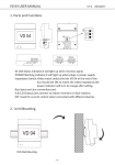
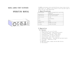
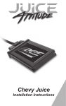
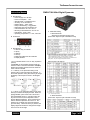
TheSensorConnection.com
Instruction Manual
A. Specifications
• Power Supply: 16 to 30 VDC
• Power Consumption: < 2W
• Sampling Rate: 4 samples/second
• Accuracy: ±0.2% full scale ±1
• Display Range: -1999 ~ 9999
• Relay Contact Rating: 1A @ 30VDC
• Retransmit Open Circuit Voltage: 15V
• Case Dimensions: 48 x 24 x 75 mm
• Mounting Cutout Dimension: 45 x 22 mm
• LED Display: 0.28” (7 mm)
• Operating Temperature: 0 ~ 50C, <85% RH
B. Front Panel
A. Specifications
1 Alarm & relay J1 indicator
2 Up key
3 Shift key
4 Set Key
5 Maximum & Minimum value indicator
6 Display Window
1. AL on indicates alarm is on & J1 relay is pulled in
(closed)
2. MAX(MIN) on when display window shows the
maximum value or the time of the MAX. MAX(MIN)
blinking when display window shows the minimum
value or the time of MIN.
3. “>“ Shift key: In the parameter setting mode,
press this key to select the digit to be changed. In
the normal operation mode, press this key to change
the display in the sequence shown in the diagram
below.
4. “˄” Up key: In the parameter setting mode, press
this key to increase the displayed value. When displaying Max/Min, press & hold it for 3 seconds to
clear the Max/Min stored. In normal function, this
key has two functions, Show Operation Time &
Change Display Brightness. Press & hold this key
down to show the Operation Time since on. Release the key to display the current temperature
(process value). Each time the key is pressed, the
display brightness will also be changed from bright
to dim or from dim to bright.
08-2014
PMD1XT-XX-024-A Digital Pyrometer
C. Parameter Setting
1. Basic Parameter
See [Fig3] for programming flow chart
(Press “SET” key then input code 0089 to enter)
Note 1: for correcting the offset at Zero: Display = measurement + PSb
Note 2: for correcting the error at Max: Display = measurement + PSbf
Note 3: Digital filter: 0=no filter, 1=weak, 2=medium, 3=strong
Note 4: These parameters define the scale boundary & resolution of the
display value. They do not apply to temperature sensors.
[Table1] Input Type Options
(TC = Thermocouple Sensor)
2. Alarm Parameter
(Press “SET” key then input code 0001 to enter)
Page 1 of 2
TheSensorConnection.com
Alarm Parameter setting is similar to the Basic
Parameters setting in [Fig3] except the access code
is 0001 instead of 0089
4. Retransmit (Analog Output)
(Press “SET” key then input code 0036 to enter)
Note 4: Relay action setting (PMD-A meter does not contain J2 relay. Its
settings (AH2 & AL2 can be ignored).
1)
Set AH1=AL1, relay is disabled
2)
Set AH1>AL1, relay is for high alarm limit. See [Fig1]
3)
Set AH1<AL1, relay is for low limit alarm. See [Fig2]
Retransmit setting is similar to the Basic Parameters
setting in [Fig3] except the access code is 0036
instead of 0089
[Fig3] Basic Parameter setting flow chart
Note 6: Output type section. User can select either 0-20 mA or 4-20 mA.
Note 7: Output lower limit. The LED display value when output is at 0 mA or
4 mA.
Example: If you want 100C to output 0 mA then set obL=100
Note 8: Output high limit. The LED display value when output is at 20 mA.
Example: If you want 1000C to output 20 mA then set obH=1000
This number will affect the resolution of the signal
D. Terminal Assignment
DC24V-
DC24V
3. Peak Value
(Press “SET” key then input code 0037 to enter)
1) 1 & 2 are for power input
2) 2 & 5 are for alarm relay output. When alarm is turned on, terminals 2 & 5
are internally connected. To drive a 24V buzzer, connect one lead of the
buzzer to the +24V. Connect the other lead to terminal 5.
3) 4 is for display brightness control. When connecting the illumination signal
(+24V) to it, the brightness will be synchronized with headlight. If not connected, the brightness can still be controlled by “˄” key.
4) 6, 7, 8, & 9 are for different type of signal input.
Example: Use 6 & 7 for EGT thermocouple probe.
5) 3 & 10 is for retransmit (analog output). To change the output from a
current to a voltage, install a 1% precision resistor between terminal 3 & 10.
250Ω resistor = 1~5VDC or 0~5VDC (depending on “obty” setting)
500Ω resistor = 2~10VDC or 0~10VDC (depending on “obty” setting)
E. Application Example
Exhaust Gas Temperature Measurement
Note 5: Peak function is interlocked.
1)
When MA is turned off, MA-t can’t be set
2)
When MI is turned off, MI-t can’t be set
Peak Value setting is similar to the Basic
Parameters setting in [Fig3] except the access code
is 0037 instead of 0089
Reset the Peak value:
The peak values are stored in the memory even
after the meter is powered off. To reset them,
change the display to show MA, MA-t, MI, or MI-t.
Then, press & hold “˄” key for 3 seconds. The
display will show “——” indicating the memory (for
all four parameters) is reset. The meter will start to
catch the new peak after 2 seconds.
08-2014
DC24V
Buzzer (optional)
The Sensor Connection
55 East Long Lake Road, #505, Troy, MI 48085 USA
Tel: 248-636-1515 [email protected]
Page 2 of 2