1
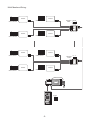
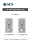
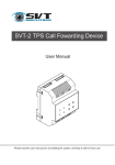
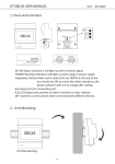
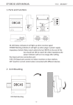
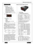
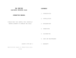
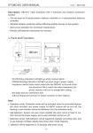
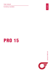
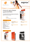
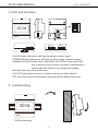
VD 04 USER MANUAL
V1.0
20120417
2
VD 04
3
ON
1. Parts and Functions
1 2 3
1
DIP
Impedance
switch
OFF
ON
POWER
IN-USE
Output
BUS
A
B
Output
C
D
IN-USE:Status indicator,it will light up when receives signal.
POWER:Working indicator,it will light up when plugs in power supply.
Impedance Switch:Video match switch,the last VD 04 at the end of the
bus should set ON to match the video impedance,the
power indicator will turn to orange after setting.
Bus:Input port,bus connection port.
A,B,C,D:Output port,connect to indoor monitors or door stations.
DIP :Used for current control when connected with different devices.
2. Unit Mounting
VD 04
DIN Rail Mounting
-1-
3. DIP Switch Setting
The DIP switch in the back of the panel is used to adjust the terminal start-up current.
Please refer to the followings for more detail informations about the DIP settings:
DIP
Bit State
ON
Descriptions
ON,OFF,OFF
The output port A,B,C,D connected with the device such as
monitor
.
OFF,ON,OFF
The output port A,B,C,D connected with the device such as
monitor
OFF,OFF,OFF
The output port A,B,C,D connected with
door station.
1 23
ON
1 23
ON
1 23
Please note that DJ1 T series and DJ LCD ID can not be connected to the same
VD 04, If it happen,please use two VD 04.
The same situation as DJ 4T ID series and DJ LCD ID model.
4. System Wiring with VD 04
Mulit Door Station Wiring:
ID=00
ON
ON
ON
1 2
12
1# Camera
ID=10
ON
ON
ON
1 2
ON
1 2
2# Camera
ID=01
1 2
3# Camera
ID=11
1 2
4# Camera
ON
1 2
1 2
monitors
L1 L2 PL S1+ S2+ S-
L1 L2 PL S1+ S2+ S-
L1 L2 PL S1+ S2+ S-
L1 L2 PL S1+ S2+ S-
A B C D
VD 04
SP18
PS5
OFF
85~260VAC
ON
Impedance
switch
-2-
Mulit Monitors Wiring:
ON
monitor
1 2 3 4 5 6
monitor
Impedance
switch
Code=14, DIP-6=on
A B C D
Code=15, DIP-6=on
ON
ON
DIP=on,off,off
monitor
Code=12, DIP-6=on
Code=13, DIP-6=on
ON
ON
1 2 3 4 5 6
1 2 3 4 5 6
monitor
1 2 3 4 5 6
monitor
Code=2, DIP-6=on
Impedance
switch
A B C D
Code=3, DIP-6=on
ON
ON
1 2 3 4 5 6
Code=1, DIP-6=on
monitor
1 2 3 4 5 6
monitor
Code=0, DIP-6=on
SP18
PS5
85~260AC
ID=00
ON
1 2
-3-
OFF ON
VD 04
1 2 3 4 5 6
monitor
OFF ON
VD 04
ON
1 2 3 4 5 6
5. Specification
Power Supply :
DC24V
Working Temperature:
-100C~+400C;
Wiring:
2 wires (non-polarity);
Dimension:
89(H)×70(W)×45(D)mm
The design and specifications can be changed without notice to the user. Right to interpret
and copyright of this manual are preserved.
VD 04
20120417