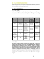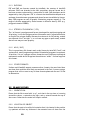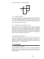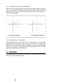
1
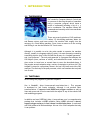
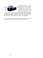
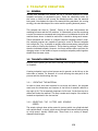
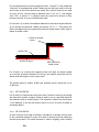
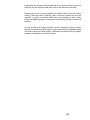
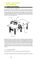
sCHOOL OF aRCHITECTURE Workshop University of British Columbia CNC Manual SCHOOL OF ARCHITECTURE WORKSHOPS CNC Milling Manual Prepared by: Nicholas Scott, Technician School of Architecture, University of British Columbia 402 – 6333 Memorial Road Vancouver, B.C. Phone 604-822-2810 Fax 604-822-3808 This is an operating manual for the CNC Routing machine at the UBC School of Architecture. It is an ongoing project, progressing as the facility evolves. The CNC MILLING manual produced by the Graduate School of Architecture and Urban Design at UCLA, (http://www.aud.ucla. edu/milling/), provided much initial guidance. Screen-captures and diagrams from Precix’s Servo Controller User Manual were used (http://www.precix.com/bill/manual.zip) as well. Contents 1 Introduction 9 1.1 The Process 9 1.2 The Tools 9 2 File Preparation 10 2.1 File importation. 10 2.2 2d and 3d files 12 2.3 3d files only 12 2.4 Notations. 13 3 Toolpath Creation 14 3.1 General 14 3.2 Toolpath creation strategies 14 4 Using the Precix CNC Machine 17 4.1 General (How it Works) 17 4.2 Safety 18 4.3 Access Procedure 20 4.4 Milling Procedure 20 1 Introduction 1.1 The Process CNC stands for Computer Numeric Control and is a process of directing the path of a machine using a computer program which issues a series of commands including a list of x, y, and z coordinates. The machine follows the commands and smoothly mills from coordinate to coordinate. There are several varieties of CNC machines: Lathes; 2-5 Axis Milling machines; Water Jet and Plasma cutters; and Laser cutters. Our machine falls roughly into the category of a 3 Axis Milling machine. Since it uses a router to do the cutting and milling it can also be called a CNC 3 axis router. Although it is possible to write the code needed to operate the machine directly, (usually in a language called G-code), it is most commonly created by translating objects from 2d and 3d CAD files by way of a “toolpath generator” and “post processor”. The tool path generator is a program that analyses the CAD objects (lines, surfaces or solids), and calculates the exact route for a given cutter to travel over or around them to carve the described shape. It may require several toolpaths using a variety of strategies to achieve this. The toolpath is stored in a proprietary format, and can’t by itself control the CNC machine. The final step is the post processor, which can translate the tool path into G-code. 1.2 The Tools We are using two programs to generate toolpaths: One is VisualMill, (http://www.mecsoft.com/index.htm ). This program is developed to just create toolpaths, although it can perform basic transformations. It supports both NURBS and polygon surfaces as well as lines and curves and so can be used with the output of any of the schools CAD and modelling programs. In addition we have SURFCAM, (http://www.surfcam.com/) a comprehensive package that includes a NURBS modeller. Being NURBS oriented it doesn’t support polygon surfaces, in fact it doesn’t even display them. It works well with files produced in Rhino and Maya. We use it for a few toolpaths that only it can produce. The milling machine is a locally manufactured Precix 9100, (http:// www.precix.com). In theory it can mill material up to 4’ x 8’ x 10 ¾”. In practice the envelope will be somewhat smaller than that. The 3hp. router is raised and lowered by a ball screw attached to carriage that moves back and forth on a gantry, which in turn moves over the large table. These three movements (z, y, and x respectively) are powered by servomotors, which can be controlled with great precision. Material is held in place on the table by suction or by T-slot clamps. The machine has its own onboard computer that reads the g-code and sends the appropriate power to the servomotors and to the router itself 2 File Preparation Before being imported to the toolpath programs all files should be prepared so that the toolpaths can be properly generated. 2.1 File importation. 2.1.1 File types. Surfcam and VisualMill are capable of opening are large number of file types between them. The format used will depend on the type of data being imported. ............................................................................................... file type extension IGES *.igs (don’t use *.iges) DWG/DXF Stereo lithography ACIS Toolpath SoA software software that supports that supports this file type this file type Maya, formZ, Rhino, SurfCam, Vectorworks, VisualMill MicroStation *.dwg/*.dxf Originally AutoCAD, now most CAD programs Surfcam, VisualMill *.stl Many 3d modeling programs VisualMill *.sat FormZ, “solid” modelers Use NURBS surfaces and curves Polygon mesh surfaces, 2d lines Polygon mesh surfaces 3d solids Surfcam 2.1.2 IGES. IGES (Initial Graphics Exchange Format) is an efficient and accurate way to import data, especially for 3d files. It was developed by the (American) National Bureau of Standards for CAD file exchange. Though it’s gradually being replaced by the STEP file format it is still a format that supports a large range of CAD entities. Because CAD programs often have proprietary methods of doing the mathematical calculations needed to create these entities, as well as creating different types of entities altogether, the IGES format has a large library of entity types which are often tweaked by software developers to create their own “flavour”. As noted above most IGES files do not support polygons. 2.1.3 DXF/DWG. DXF and DWG are formats created by AutoDesk, the creators of AutoCAD software. DWG was intended to be their proprietary internal format but it has been reverse engineered by a consortium of other CAD developers and is supported by their programs. DXF is a format that AutoDesk developed as an exchange format between programs and whose format is available by license. Many CAD programs as well as graphic illustration programs support it. The range of entities supported by these formats is different than by IGES (e.g. polygons instead of NURBS). 2.1.4 Stereo Lithography (*.stl) The *.stl format is a polygon mesh format, developed for rapid prototyping and 3d printing. It will save polygon surface information and is a good alternative to dwg/dxf for polygon models. Because its main use is for 3d printing, models are expected to be “air-tight” (i.e. not have any gaps or open areas), models that are not may not save properly. 2.1.5 ACIS (*.sat) This is a proprietary file format used, under license by AutoCAD, FormZ, and various other, mostly engineering oriented 3d modeling programs to represent 3d entities. It is not a polygon surface format but uses a different topological mathematic model which recognizes the entities as “solids”. Surfcam supports this format. 2.1.6 Other Formats Surfcam and VisualMill support numerous other formats; the ones listed here are those that would be most likely encountered in the SoA. If you are using a program that will not save to any of these formats please ask me and I’ll find an alternative. 2.2 2d and 3d files 2.2.1 Orientation. Ensure that the file is saved with “z up”, such that in the top view +z is coming toward the viewer, +x extends to the right, and +y extends towards the top of the screen. Otherwise the model will import rotated. 2.2.2 Location of Object. Ensure that the part to be milled is located so that it is situated in the positive x,y quadrant and that any thickness it has extends from z=0 down into the 10 direction of negative z (see following diagram). y Z X -X -y -Z 2.2.3 Lines and Curves It is important to ensure that lines and curves used to create the shapes to be cut out with 2d toolpaths are continuous. There should be no gaps. It’s safest to use only joined polylines and continuous splines. Also ensure that there are no lines or curves left directly under others. Both gaps and double lines confuse the toolpath creation software. 2.2.4 Bounding Box and Boundary Lines. Often it’s useful to create a bounding box around the part. This should be constructed to create a solid representing an area equal to the greatest extents of the part. This can be used in the toolpath program to help define the material to be removed. The bounding box should have 2 of its edges on the x=0 and y=0 lines and one corner at 0,0,0. If only part of the model is to be machined, create a boundary delineating this area at z=0 such that in the top view it acts as a frame for the area to be cut. 2.2.5 Spacing of 2d objects When cutting completely through material it is important to leave an uncut margin at the edges and between the shapes being cut out so that the material maintains its integrity during machining. There should be a margin of 1” between the edge of the material and any shape to be milled. Also there should be a gap of ¾” to 1” between shapes. 2.3 3d files only 2.3.1 Location of 3d Model Place the object(s) as close to the x,y plane in the z-axis as possible while fulfilling requirement (2.2.2). Because the x,y plane represents the top of the material being cut this minimizes the amount that has to be removed before the part is exposed. 11 2.3.2 There should be no undercuts. Because a 3 axis milling machine can only travel vertically without rotating in the x,z or y,z planes the bottom of a part must be at least as wide, when seen from above, as the top. Undercuts will either be ignored or will create errors. (See following diagram). 2.3.3 Integrity of the model. Care should be taken to insure that the part is “watertight”, i.e. with no gaps between surfaces, when seen from the top (plan) view. The machine only works vertically from the top so that completely vertical surfaces or gaps are invisible to it. However if a gap has any horizontal dimension then it is visible and can cause problems with machining. 2.4 Notations. In all cases notation objects such as dimensions and leaders should not be exported from the original CAD file. 12 3 Toolpath Creation 3.1 General Surfcam and VisualMill will analyze the 2d or 3d data imported to create toolpaths according to parameters given. These are essentially routes for the cutter to follow to mill (carve) the finished product from the material being used. You stipulate the size of the material being machined, the cutting strategy, the size and shape of the cutter and the spacing between passes. This toolpath can then be “Posted”. Posting is the final link between the modeling software and the CNC machine. It is essentially a text file containing a series of movement commands and a long series of coordinates which let the machine know where it should be and what it should be doing each instant. These commands are written in a simple computer language called G-code. Our toolpath programs are capable of posting a series of discreet toolpaths into a single file, (e.g. a toolpath to quickly remove unnecessary material plus one or more to clean up the surfaces). This is done by posting a “Setup” rather than the individual toolpath. However the Precix machine has no provision for changing cutters in the middle of a post so multiple toolpaths posted together should have the same cutter. 3.2 Toolpath creation strategies Because we are phasing out the use of SurfCAM, most toolpaths will be created in VisualMill. Creating toolpaths is an involved process and in general can be left up to the technician or student T.A. However it is worth knowing the main parts of the process and the choices along the way. 3.2.1 “Creating” the material In order to know how much material to cut away and where, the program must know the dimensions and location of the block of material relative to the origin (0,0). This is especially important for 3d work. So the first step is to define and locate the material. This step is made much simpler if the model is located as stipulated in the last section. 3.2.2 Selecting the cutter and spindle speed The actual cutting is done with a router bit (cutter) which is a cylindrical shaft with carbide flutes, or teeth, which moves through the material while spinning at a high speed, (usually 18,000 rpm). These come in a variety of shapes, diameters and lengths. 13 For our purposes there are two categories of bits: “end mill” or flat ended and “ball nose” or hemispherical ended. Usually the end mills are used for 2d cuts and 3d cuts in which the surfaces are mostly flat, and ball nose bits are used for curvy 3d cuts. Our bits range in diameter from 1/16” to ¾”, with lengths from 3/16” to almost 3”. In general router bits need to be shorter as they become narrower so as not to break under load. For 2d work I try to select the smallest diameter bit that has a length sufficient to cut through the material. Usually this means 1/8” or ¼”. This choice will affect the shapes being cut because the machine always leaves a fillet when it makes an inside corner. no fillet at outside corner path of tool outline of object fillet created at inside corner For 3d work I try to select the largest bit that will allow the detail needed to be carved. A smaller diameter bit will get into smaller spaces but will be shorter and take longer to mill a given area. The spindle speed is usually 18,000 rpm although acrylic should be cut at 12,000 rpm. 3.2.3 2d toolpaths For 2d work two toolpaths are most often used. Contour is used to cut through the material to extract a shape. Pocket is used to cut to a specified depth all the material within a closed polyline. The toolpath is offset from the polyline ½ the diameter of the bit and directs the bit to cut in a series of passes at increasing depths. 3.2.4 3d toolpaths In most cases the first stage of milling a 3d shape is to quickly remove most of the unwanted material in order to be able to directly mill the underlying surfaces more easily. This initial operation is called “roughing” and is usually 14 accomplished by cutting unwanted material of in a series of steps or layers. At each step the bit follows a spiral path until all the material is removed. Following this, one or more toolpaths are created which trace the surface directly. These are called “finishing” paths. The most common one cuts the material in a series of parallel paths rather like ploughing a field. Others follow the NURBS isoparms or concentrate on smoothing vertical or horizontal surfaces. You can choose at this stage whether it is more important to get a smooth surface or to finish the milling quickly. Larger steps between the parallel paths will mean rougher but faster milling. Sometimes the patterns left by rougher toolpaths are wanted for aesthetic reasons. 15 4 Using the Precix CNC Machine 4.1 General (How it Works) 4.1.1 Structure of the machine. The largest part of the CNC machine is a 4’ x 8’ table on which the material is placed. Crossing the 4’ length of the table and running on tracks along either side is a gantry upon which a second set of tracks enables a screw mechanism to move horizontally back and forth. The screw mechanism controls the vertical movement of the router itself. The 2 tracks and the screw control movement in the x, y, and z-axes respectively. Gantry Router Table Controller Beneath the table is a controller, which is a computer specially configured to control the power to the servomotors and the router by taking the instructions in the Post and translating them, in real time, into modulations in the electrical current. In order to do this the controller uses a special UNIX operating system called QNX. When the controller boots up, the Precix controller interface automatically loads so that the operating system remains essentially invisible. There is a monitor and a roller-ball input device for setting up jobs and changing settings. 4.1.2 Holding material. The material to be cut can be held in place on the table several ways: The machine is equipped with a set of 4 vacuums that create suction on each of 16 the 4 quadrants of the table. However this system is underpowered and unless the entire area that the vacuum serves is covered, it will not be effective. There are 6 cam clamps that connect to “T” slots in the table. These, in combination with filler strips of various widths, hold very well. Care must be taken to ensure that the cutting tool will not hit them! If the cutter hits a metal object it could shatter! Double-sided tape seems to work for very small pieces of material. There are various types that should be considered relative to the size and type of the material. 4.1.3 Orientation of Axes. 0x,0y is located at the corner of the machine nearest to the door of the computer room. The x axis runs along the longer side of the table and the y axis goes across it. 0z is at the highest point that the screw will allow the router to go. 0x,0y,0z is called the home position. 4.1.4 Power. The machine is started by turning on the controller, (blue button). This will launch the controller interface through which the servomotors and the router (called “spindle” on the interface) can be started. The router (spindle) must also be plugged in at the wall. Unplugging it overrides the interface on/off and is a safety measure for cutter changes. 4.1.5 The Controller Interface. The interface is a split window, with virtually all functions controllable using a Controller interface pointing device (roller ball). The left window doesn’t change and gives information about the cutter location, the origin location, a schematic 17 representation of the table in plan view, and buttons for moving the machine along the 3 axes manually. Any number field can be filled by clicking on it. A numeric keypad will be displayed on which the numbers can be entered using the roller ball. I won’t go into the interface in detail. Basically once the post file is imported the Job Output window is brought up. The file can then be previewed, the speed with which the machine will move through the material can be set as well as the speed the spindle is rotating. There are buttons to start, stop (pause), reset and release the job. A brief explanation of the operating proceedure is given after the Safety section. 4.2 Safety 4.2.1 Limits of Access. The CNC machine is only to be used by individuals authorized to do so by the technician and who have been trained in its use. They must have previously completed the general Workshop Orientation, signed the waiver, and paid their insurance fee. Those without training who wish to have models milled must make arrangements with the technician. Assistants will be trained in order to make the machine as available as possible. See 4.3. 4.2.2 Safety Guidelines. 1. All safety rules in the workshop Operational Policies must be followed. 2.Everyone in the CNC room must wear safety glasses and if necessary hearing and dust protection while the machine is in operation. 3. The operator must remain in the CNC room at all times while the machine is running. If you must leave the machine must be stopped while you are absent. (Click resume to restart). 4. There is very little space around the machine. Care should be taken to keep out of the way of the gantry, which moves back and forth along the table. Be careful when passing another person. 5. Keep cursor close to the stop button. 18 6. Keep your hands away from the area where the cutter is working. The machine can change direction without warning and travels quickly when not actually cutting. 7. Keep the table of the machine clear of everything except the model being milled. Do not use it as a workbench or for storage. 8. Keep the part clean of chips and debris. If the dust exhaust hose is not attached to the machine the model must be “manually” vacuumed. Take care to keep the hose and your hands out of the way of the cutter. 9. If a work piece begins to vibrate or the cutter makes excessive noise, stop cutting immediately. 10.Make sure that the material to be milled is securely held in place. Make sure clamps and fixtures are not in the path of the cutter. 11.Before starting the spindle, make sure it is free from the work piece and any other obstacles, (e.g. wrenches!!). When starting spindle in the home position warn anyone standing in the area. 12.IF ANY ASPECT OF THE OPERATION OF THE MACHINE IS CONFUSING OR SEEMS WRONG STOP EVERYTHING AND GET ASSISTANCE. THIS IS A VERY EXPENSIVE AND POTENTIALLY DANGEROUS TOOL. 13.When finished: • Home machine. Turn off machine and controller. Unplug spindle. • Remove and return to storage the cutter you have been using. • Remove the part and put away spacer boards and extra clamps. • Vacuum the table, gantry, and router. Sweep the floor. Tidy up. • Save and/or remove any data on the computer, then turn it off. Take whatever you brought with you. Turn out lights. 19 4.3 Access Procedure There is a sign-up book in front of the Workshop office. Generally we try to handle a job in the morning and one in the afternoon. This will vary according to the complexity and size of the job; please ask the technician for advice on how much time you will need. Extra jobs after workshop hours can sometime be arranged by request. As always first priority is given to students working on studio or class projects. 4.4 Milling Procedure This section gives an overview of the steps to followed to begin milling. However this should always be done under the supervision of the technician or a qualified monitor. See 4.2. 1. Check toolpath and verify on the local computer. Let supervisor see and confirm it. Prepare the post. See 3.8 2. Turn on controller. Let it boot up and launch the interface. 3. Position and clamp material to be cut to table. See step 7 below and 4.2.1. 4. Drop toolpath(s) onto Queue shortcut on desktop of local computer. 5. On the Precix interface, click on the “Power On” button. Click on the “Homed” button. This will bring the spindle to its base 0,0,0 position and recalibrate it. 6. Select, insert and tighten cutter in the collet of the router. See 4.3.3. 7. Set origin. This is the point in real space that will correspond to the 0,0,0 position in your model. To do this, use the arrow keys to move (“jog”) the tip of the cutter to the top corner of the material closest to the home position. The small arrows will move the cutter head 1/10 the speed of the large ones. 20 There is usually a curb attached to the table the corner of which is at 6,6. This is a convenient way of setting the origin for x and y. Use the number fields in the Job Origin area to enter the origin. Click the “Move to Origin” button and the machine will move to the x,y origin point if this has already been entered. Use the downward arrow to jog the cutter down until the tip just touches the top of the material. If you just tap the button the machine will move in small amounts. Set this point as z0. by clicking on the “z0” button. You have now defined the zero point of your material in 3 axes. Set the “z up” to at least 1.0. This is the height above z0 at which the machine moves from cutting area to cutting area (rapid moves). Set the zm (z maximum) for the lowest point relative to the Z0 that the cutter will be permitted to go. This setting overrides any instructions from the Post and is a safety measure to prevent damage to the table. It is very important that the Z0 + Zm = a point which is above the surface of the table. See 4.4.4, “Calibrating Z Levels”. 8. Preview the cutting path, making sure it is where you expect it to be and the right shape. 9. Set Cutting Speed. Click the field and enter a number. Click the cutting speed button to override the Surfcam instruction. See 4.4.1. 10.Set the Spindle Speed. See 4.4.2. 11.Turn on exhaust. The hose can be attached to the router with “Zap Straps” or the vacuum cover plate can be used. 12.Turn on “spindle” (router) if not set to auto. 13.Put on goggles and, if necessary, hearing protection. 14.Click Start. 15.If the cutting needs to be paused to remove cut objects or to clear debris click the STOP button. This will pause the process. The STOP button will change to a START button which can be clicked to continue the cutting. 21 16.When finished: Home machine. Turn off machine and controller. Unplug spindle. Remove and return to storage the cutter you have been using. Remove the part and put away spacer boards and extra clamps. Vacuum the table, gantry, and router. Sweep the floor. Tidy up. Save and/or remove any data on the computer, then turn it off. Take whatever you brought with you. Turn out lights. 4.4.1 Cutting Speed. This is also referred to as the “feed rate”, and determines the rate at which the machine moves the cutter across the material in inches/second. (As opposed to the rotational speed of the cutter, which is the “spindle speed”). The cutting speed must be set in relation to the size of the cutter, the material and the depth of cut. A ¼” cutter going through foam at a 1/8” depth could be fed at a rate of 4 or 5 in/sec. But through dense wood or MDF that rate would break the cutter; (it couldn’t cut fast enough to keep up). So in such a case 1 or 2 in/sec would be appropriate. If in doubt start with a slower rate and gradually increase it. 4.4.2 Spindle Speed. The spindle speed is the rotational rate of the cutter in revolutions/second. The milling machine is essentially a router and routers rotate at very high speeds, (up to 22,000 r/s). At this stage we have been running at 18,000 r/s through foam and MDF with no problems. The UCLA manual indicates they use a 30% slower speed for cutting acrylic or aluminum. 4.4.3 Cutters. For our purposes the terms cutter, tool and bit can be used interchangeably. The machine uses both conventional straight flute wood router bits as well as spiral fluted end and ball mills. I think straight flute bits are a bit more robust for a given diameter but spiral flutes have better chip clearing properties. For cutting foam and wood both types can be used. For plastics and soft metals only spiral-fluted bits should be used. The workshop’s selection of tools is much more limited than the choices available in the Surfcam tool libraries. Check with technician or TA for what is available. 22 4.4.4 Calibrating Z levels. Calibrating Z levels bottom of gantry Baseline “0” maximum 12“ above table Zup = rapid or retract plane. Z0 = top of material. Zm = max. depth of cut. top of table Baseline is the maximum height of cutter above table it is shown as the “0” Z value in the “absolute” coordinates. (this point is 12“ above the table assuming cutter extends 1.5” below collet. it should be noted that although the cutter can be retracted 12“ above the table, the bottom of the gantry is only 10 3/4” above the table.) Z0 is the absolute distance from the baseline to the top of the material. it is set by “jogging” (or moving the cutter with the arrows on the computer interface) down ‘til it just touches the highest point of the material. Zm is the maximum depth of cut. it is set relative to Z0. therefore Z0 + Zm < 12“. Zm should always give a point slightly above the table (e.g. 0.25”) to avoid gouging the table. Zup is the plane that the cutter travels in when moving from point to point in the toolpath. it should be at least 0.25“ above the table. 23