1
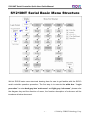
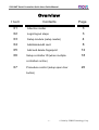
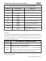
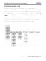
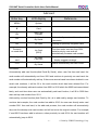
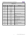
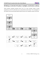
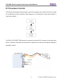
SYRIS SY210NT Series
Quick User Guide Manual
Control up to 4 doors with in/out reader
Baud rate 2,400 - 115,200 bps
Ver : 2.00
SY210NT Serial Controller Quick User Guide Manual
SY210NT Serial Basic Menu Structure
We list SY210 basic menu structural drawing here for user to get familiar with the SY210
serial controller operation procedure. The first step is to execute the white box “ Login
procedure” to enter dark gray box “main menu” and light gray “sub-menu”, please refer
the diagram key and the direction of arrow, the function description of sub-menu will be
introduce at below document.
-1-
© 2004 by SYRIS Technology Corp.
SY210NT Serial Controller Quick User Guide Manual
Overview
Item
Contents
Page
01
Attention matter
3
02
Login/logout steps
3
03
Setup module (setup reader)
4
04
Add/delete/edit card
8
05
Add and delete fingerprint
12
06
Setup controller ID (when multiple
18
controllers online)
07
Procedure control (setup open door
20
button)
-2-
© 2004 by SYRIS Technology Corp.
SY210NT Serial Controller Quick User Guide Manual
01 Attention matter
Install:
When the user ready to install SY210 serial controller, please open the controller cover on
the back (TSN and SSN model) and confirm the white disconnect film has been removed.
When the user first time connect the power, all the lights flash and produce serial sound,
please proceed system replacement by click 1 key according to the controller LED display
(1:Clear)
Setup:
The controller and reader factory default ID all set to “1” Please setup ID first before
connect multiple controller or reader to avoid ID repeat cause communication failure.
Please refer the reader ID setup method of page 5 “Setup module”. And about controller ID
setup please refer page 17 “Setup controller ID”
02 Login/logout step
The SY210NT controller needs to complete the login step to enter function menu. The
controller will automatically logout when the user stops operating about two minutes.
However, in order to confirm the door access security, please execute logout steps after
finish setting.
Login Step
Enter key
LCD display
Reference
MENU
System
EN
Login
EN
Password
Wait for password enter
1+2+3+4+EN
Master OK
Setup light flashes, already in login status
-3-
© 2004 by SYRIS Technology Corp.
SY210NT Serial Controller Quick User Guide Manual
Logout Step(in login status)
Enter key
LCD Display
Reference
MENU
System
EN
Login
▼
Logout
EN
Display date and time
Setup light goes out, complete logout
step.
* The below steps pre-set in login status
03 Setup Module (setup reader)
After install controller and reader, the user needs to setup reader ID and scan
communication status from controller (plug & play) to normal transmit the I/O data. The
next diagram is System main menu table and the gray part is the step operation range.
-4-
© 2004 by SYRIS Technology Corp.
SY210NT Serial Controller Quick User Guide Manual
Setup reader ID
Enter key
LCD display
Reference
MENU
System
EN
Login
▼*5
System
Process
EN
APBLevel
Seting
▼*2
Change
ModuleID
EN
Module
[READER]
EN
Serial
03150001
Enter module serial number(annotate 2)
EN
ModuleID
ID = [ 1 ]
Setup module ID (annotate 3)
EN
Change
ModuleID
Setup complete, back to item
Modify/setup module ID item
Use ▲▼ key to choose the installed
module type (annotate 1)
Annotation 1: Module type
READER
General proximity reader, including SYRDS1、S5、L5。
DIDO
Digital contact expand module, including MDDIDO-1S、MDDIDO-16。
PRINT
Printer module
SYRDK5
Keypad proximity reader
SYRDF5
Fingerprint proximity reader
SYRDT5
LCD display card reader
Annotation 2: The user can find the serial number sticker from card reader package or
machine back.
Annotation 3: Card reader ID arrange rule
Door
Door one
Door two
Door three
Door four
Incoming reader
ID 1
ID 2
ID 3
ID 4
Outgoing reader
ID 5
ID 6
ID 7
ID 8
Function
-5-
© 2004 by SYRIS Technology Corp.
SY210NT Serial Controller Quick User Guide Manual
Scan communication from controller (plug & play)
Enter key
LCD display
Reference
MENU
System
EN
Login
▼*3
Module
Process
EN
ADD
Module
▼*3
Module
PlugPlay
Scan module communication item
EN
Module
Waitting
Scanning communicated module
Please wait
Find:01
OK
Display communicated module
amount(annotate)
CLR
Module
PlugPlay
Setup complete, back to item
Annotation:
The controllers will automatically display the plug & play result. In normal status, the display
module amount will match with the practical installed module amount. In another word, the
scan result should display: Find: 04 OK. If the display amount is unusual, please refer the
below table to eliminate the issue.
Unusual
situation
Possibility
Scan (display 00) or display less amount
The communication is not correct or repeat ID
◎Please confirm the communication again
Eliminate
method
◎The factory default of reader ID all set to “1”. The ID did not setup
properly when communicated with multiple reader or ID repeat cause
transmission conflict and can not find the module correctly.
Please contact with the Syris technical personnel if confirm the above questions but still can
not communicate correctly.
-6-
© 2004 by SYRIS Technology Corp.
SY210NT Serial Controller Quick User Guide Manual
04 Add/delete/ edit card
The add card function separate into (Add Card By Serial) or (Add Card By No. )
The edit card function is for setup card enable/disable (Status Setting), passage application
group (APP Setting), card password (PIN Setting) and anti-pass-back function (APB
Setting)
Delete card can separate into (Del Card by No.) or (Delete All Card). The next diagram is
the Card main menu table and the gray part is the step operation range.
-7-
© 2004 by SYRIS Technology Corp.
SY210NT Serial Controller Quick User Guide Manual
Add card
Enter key
LCD display
Reference
MENU
System
▼
Card
EN
Add Card
Process
EN
Add Card
By Serial
Automatically sort add card module
(annotate)
EN
Ins Card
Waiting for proximity un-gotten card
Proximity
un-used card
Ins Card
[0001]
First time enter card sort from 0001,
serial proximity new card will
automatically increase card number.
Proximity using
card
Ins Card
Card Use
If card has been used, the screen will
display suggest message
CLR
Add Card
By Serial
Leave automatically add card mode
Annotation:
Automatically add card function(Add Card By Serial), when user first time add card, the
card number will automatically sort from 0001 and continue to proximity un-used card, the
card number will automatically add up. If there are several cards have been deleted in one
serial card numbers, it will be fill in the card number which has been deleted first. For
example, the already add card number from 0001 to 0010 which the 0005 has been deleted
lately, and next time when user use automatically add card function, it will fill in 0005 then
start add up card number from 0011.
Add card by number function (Add Card by No.) is to add card by assign card number. To
continue last example, the card number has add to 0010, the user can directly enter card
number 0011 then add card, in the add card process, the card number will automatically
skip over the already exist card number and will not cover the original number. For example,
if card 0015 has been add in advance, when proximity to card 0014, the card number will
automatically jump to 0016.
-8-
© 2004 by SYRIS Technology Corp.
SY210NT Serial Controller Quick User Guide Manual
Edit Card(enable/disable)
Enter key
LCD display
Reference
MENU
System
▼
Card
EN
Add Card
Process
▼
Modify
One Card
Edit card item
EN
Card No
No:0001
Enter the card number which want to
edit
EN
Status
Setting
Card enable/disable setup mode
EN
Card
[Enable]
Card normal status is enable
▼
Card
[Disabl]
Set up card to disable
EN
Status
Setting
Card has been modified, back to item
The other function of edit card, we suggest the user co-operate with SYW95A door access
manage software to proceed setting, the description of each function is at next page:
Passage Application Group (APP Setting):
Able to setup card (holder) group (max.16 groups). Co-operate with SYW95A door access
manage software can setup the passage timer and passage door.
Card password (PIN Setting):
Install keypad proximity reader can setup card (holder) personal password, though
SYW95A door access manage software can setup open door mode to “card plus
password”.
Anti-pass-back (APB Setting):
Base on “one in one out” control idea to avoid one card repeat incoming/outgoing situation,
mostly apply to parking space management or research centre personnel management.
-9-
© 2004 by SYRIS Technology Corp.
SY210NT Serial Controller Quick User Guide Manual
Delete Card
Enter key
LCD display
Reference
MENU
System
▼
Card
EN
Add Card
Process
▼*2
Del Card
Process
EN
Del Card
By No.
Delete card by no. mode
EN
Del Card
No:0001
Enter the card number which wants to
delete.
EN
Del Card
By No.
Card has been deleted, back to item
▼
Delete
All Card
Delete all card mode
EN
Delete
[No]
Confirm delete or not
▼
Delete
[Yes]
Choose Yes
EN
Delete
OK
All cards have been delete
CLR
Delete
All Card
Back to item
- 10 -
© 2004 by SYRIS Technology Corp.
SY210NT Serial Controller Quick User Guide Manual
05 Add and delete fingerprint (need to install fingerprint module)
SY210 serial controller can proceed door access control by identify fingerprint through
fingerprint module (SYRDF5). Able to setup card replace by fingerprint or fingerprint
corresponding to card to attend the “fingerprint control” function. The setting of
fingerprint corresponding to card is for one card corresponding to ten fingerprints, out
suggestion is to use the Syris fingerprint manage software (SYFPM).
In the follow steps, we are going to introduce how to add/delete fingerprint and setup card
replace by fingerprint, the next diagram is the Finger Print main menu table and the gray
part is the operation range of this step.
- 11 -
© 2004 by SYRIS Technology Corp.
SY210NT Serial Controller Quick User Guide Manual
Add Fingerprint(co-operate with SYRDF5)
Enter key
LCD display
Reference
MENU
System
▼*3
Finger Print
EN
Finger
ID = [1]
Select fingerprint module(ID)
EN
Add
Finger
Add fingerprint mode
EN
Finger
No:0001
Enter the fingerprint number which
wants to add
EN
Add
Finger
Press finger when F5 light flashes and
produce sound (annotate)
Fingerprint item
Delete Fingerprint
Enter key
LCD display
Reference
MENU
System
▼*3
Finger Print
EN
Finger
ID = [1]
Select fingerprint module(ID)
EN
Add
Finger
Add fingerprint mode
▼
Delete
Finger
Delete fingerprint mode
EN
Delete
By No
Delete card by number mode
EN
Finger
No:0001
EN
Delete
Finger
Fingerprint item
Enter the fingerprint number which
wants to delete
The fingerprint has been deleted
- 12 -
© 2004 by SYRIS Technology Corp.
SY210NT Serial Controller Quick User Guide Manual
The function of “card replace by fingerprint” is simply passed by fingerprint without using
card at all. The user has to add fingerprint from Finger Print item then enter Card item
and select “card replace by fingerprint” to add card.
Card Replace by fingerprint(after add fingerprint from Finger Print)增加
Enter key
LCD display
Reference
MENU
System
▼
Card
EN
Add Card
Process
EN
Add Card
By Serial
Automatically add card mode
EN
Ins Card
Waiting for proximity un-used card and
replace by fingerprint here
Press finger
Ins Card
[0001]
Card replace by fingerprint
Annotation: The attention matter of press fingerprint
In order to maintain the fingerprint identify rate in standard value, please pay attention on
the below introduction of press fingerprint:
The fingerprint sampling method is to get many minutiae extend from the
fingerprint center as the right image, the cross curve center is the fingerprint
center
Please locate the fingerprint center and aim at effective proximity area center (as next
picture) , then press finger on the effective proximity area softly, now the finger tip should
parallel with the “ position ceiling”, therefore, the user can also according to the “position
ceiling” to locate the fingerprint
- 13 -
© 2004 by SYRIS Technology Corp.
SY210NT Serial Controller Quick User Guide Manual
The correct and incorrect examples of pressing fingerprint:
○
Correct: the finger tip parallel with “position
ceiling” and locate the fingerprint center in the
middle, press the fingerprint in the effective
proximity area
X
Error:the fingerprint only touch
the effective
proximity area lightly and can not be identify
X
Error: the fingerprint center not locate in
effective proximity area properly, the sampling
is not enough
X
Error: the finger is not press equally in the
effective proximity area, less contact area and
can not be identify
X
Error: the finger position is too lean on one side
and can not be identify
- 14 -
© 2004 by SYRIS Technology Corp.
SY210NT Serial Controller Quick User Guide Manual
When SYRDF5 is identifying the fingerprint, it will remind the user the current status by
signal lights and beep, the description as follow:
Action
Press
fingerprint
Fingerprint
correct
Fingerprint
incorrect
SYRDF5 Signal
One short beep, the power light
successive flashing
One long beep, “OK” light
flashes once
One long beep and three short
beeps, error light flash one
long and three short times
SYRDF5 Status
Verifying the fingerprint minutiae, can
remove the finger
Find the fingerprint data, and identify the
status
Can not find the fingerprint data, or press
way error can not identify the status
The mainly reasons of common fingerprint identification failure:
(1)The finger moved or pressed incorrectly:
→Please follow the description above to enroll fingerprint correctly.
(2)Avoid wet and oily finger(especially rainy day or the personnel who touch grease):
→Please wipe the finger with towel then press fingerprint.
(3)The finger too dry to display the clearly fingerprint:
→Please re-press the fingerprint or wet the fingertip with a breath then press the
fingerprint.
(4) Can not contrast with the recorded fingerprint because of the finger peeling or serious
injured:
→Please re-enroll other fingerprints
(5)The employees data or fingerprint data come from other machine or transmit through
Internet, the system didn’t initialize after enroll fingerprint:
→Exit the system then re-enter the program to make the system data initialized
- 15 -
© 2004 by SYRIS Technology Corp.
SY210NT Serial Controller Quick User Guide Manual
06 Setup controller ID (when multiple controllers online)
When multiple controllers operate online, the ID of each controller needs to setup
separately to avoid ID conflict and cause communication abnormality. The next diagram is
the System Process main table and the dotted line part is the operation range of this step.
- 16 -
© 2004 by SYRIS Technology Corp.
SY210NT Serial Controller Quick User Guide Manual
Setup Controller ID
Enter key
LCD display
MENU
System
EN
Login
▼*5
System
Process
EN
APBLevel
Setting
▼
Control
ID
EN
Control
ID:0001
EN
Control
ID
Reference
Setup controller ID item
Enter the controller ID number(1~99)
which wants to assign
Complete the controller ID setting
- 17 -
© 2004 by SYRIS Technology Corp.
SY210NT Serial Controller Quick User Guide Manual
07 Procedure Control
SY210 pre-set through setup procedure control, the program can control functions to attain
to the different functions demand. Next diagram is the example of setup press button to
open door method
The DO1 of SY210NT-TSN connects to electric lock and the DI1 connects to the open door
button. Therefore, the action of press button to open door can be done though the setting of
procedure control.
- 18 -
© 2004 by SYRIS Technology Corp.
SY210NT Serial Controller Quick User Guide Manual
Procedure control (Press button to open door setting)
Enter key
LCD display
MENU
System
EN
Login
▼*2
Flow
Process
Procedure control menu
EN
Add Flow
Control
Add procedure
EN
Reference
Flow
No:35
First time start with the 35th procedure
(the number before 35 are all controller
assign procedures)
Event
Setting
The event item is the condition of setup
open door action
EN
Event
CardSenc
▼*12
Event
DI On
We connect the open door button to
controller DI1, so select DI On for input
signal.
EN
Event
ID = [9]
Select the event source module, setup
module ID: 9 which mean the signal
source is controller.
EN
Event
Ch:[01]
Select event channel, this case setup
open door button connect to controller
DI1, so choose channel 1
EN
Event
Delay:00
Event delay time, we can decide delay
how many sec. to open door when DI
open door signal touch off.
EN
Event
Setting
Event setup complete.
▼
Action
Setting
Action setup item, setup the action after
open door signal touch of.
EN
Action
LED
- 19 -
© 2004 by SYRIS Technology Corp.
SY210NT Serial Controller Quick User Guide Manual
▼*3
Action
SY210 DO
In this case, the electric lock connects to
controller DO1, so the controller DO
execute the action.
EN
Action
[Open]
Setup receive open door signal, the
Realy action is “open”
EN
Action
Ch:[01]
Select the action channel, output byDO1
EN
Action
Setting
Complete the action setting (to be
continued)
Procedure Control(setup open door button)
Enter key
LCD display
Reference
▼
Method
Time
Setup action time
EN
Method
[Alway]
Setup time mode
▼*2
Method
[Sec]
Choose count by second
EN
Method
Time:003
Setup time: 003 (three seconds)
- 20 -
© 2004 by SYRIS Technology Corp.