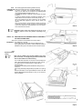
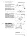
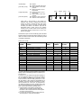
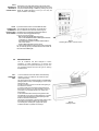
1
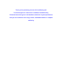
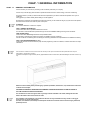
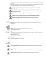
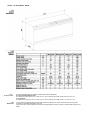
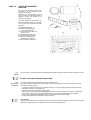
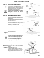
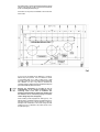
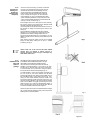
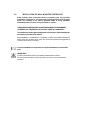
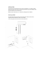
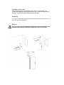
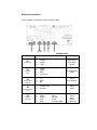
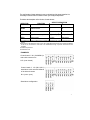
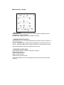
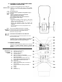
INSTALLATION
OPERATING &
MAINTENANCE MANUAL
Compact Pro
Thank you for purchasing a Lennox Air Conditioning unit.
You have bought one of the best air conditioners available today.
Follow the instructions given in this booklet to obtain the very best performance
from your air conditioner and to enjoy a fresh, comfortable Summer in complete
well-being.
INDEX
Chap. 1 GENERAL INFORMATION
1.1
1.2
1.3
1.4
General information
Symbols
1.2.1
Editorial pictograms
1.2.2
Safety pictograms
Technical data
1.3.1
Overall dimensions
1.3.2
Technical features
1.3.3
Technical notes
1.3.4
Proper use
List of accessories supplied
1.4.1
Storage
1.4.2
Receipt and unpacking
page 3
page 4
page 4
page 4
page 5
page 5
page 5
page 5
page 5
page 6
page 6
page 6
Chap. 2 INSTALLATION
2.1
2.2
2.3
2.4
2.5
2.6
2.7
2.8
Instructions for installation
Selection of position of the unit
2.2.1
Choice of best position for installing the air conditioner
2.2.2
Dimensions and features of site where air conditioner is installed
Installation of the unit
2.3.1
Drilling the wall
2.3.2
Provision for draining condensate for machines with heat pump
2.3.3
Installation of air pipes and external gratings
2.3.4
Power supply connection
2.3.5
Fitting the unit on bracket
Preparation for assembly/installation at high level
2.4.1
Introduction
2.4.2
Removal of front casing
2.4.3
Preparation of unit
Working tests and identification of possible malfunction
2.5.1
Evacuation of condensation water in case of emergency
Periodical maintenance
Installation of Fresh Air Kit
Installation of Wall Mounted Controller
page 7
page 7
page 7
page 7
page 7
page 8
page 10
page 10
page 11
page 12
page 12
page 12
page 12
page 13
page 13
page 15
page 15
page 16
page 17
Chap. 3 USE AND MAINTENANCE (for the user)
3.1
3.2
3.3
3.4
3.5
3.6
3.7
3.8
3.9
Important Recommendations
Names of parts
3.2.1
List of Units
3.2.2
Description of signal console
Control of Air Conditioner using the remote control unit
3.3.1
Remote control
3.3.2
Insertion of batteries
Remote control
3.4.1
Description of the remote control
3.4.2
Switching on and control of operation
3.4.3
Switching the unit on and off (button T1)
3.4.4
Automatic Operation (button T2)
3.4.5
Cooling function
3.4.6
Dehumidifier only
3.4.7
Fan only
3.4.8
Heating function (only models with heat pump)
3.4.9
Control of air flow direction
3.4.10
Control of fan speed
3.4.11
External air intake
3.4.12
Night operation
3.4.13
Setting programs for operation
3.4.14
Setting of correct time
3.4.15
Setting of time schedules for 1st and 2nd Operating Program (PROGR. 1 and PROGR. 2)
3.4.16
Starting and stopping operating programs
3.4.17
Resetting all functions of remote control
3.4.18
Control of Air Conditioner if remote control is not available
Maintenance
3.5.1
Cleaning air filter
Troubleshooting
3.6.1
Functional aspects that should not be mistaken for malfunctions
Recommendations for energy savings
Troubleshooting
Spare Parts
page 26
page 26
page 26
page 26
page 27
page 27
page 27
page 27
page 27
page 28
page 28
page 28
page 28
page 29
page 29
page 29
page 29
page 30
page 30
page 31
page 31
page 31
page 32
page 32
page 33
page 33
page 33
page 33
page 34
page 34
page 34
page 35
page 36
CHAP. 1 GENERAL INFORMATION
CHAP. 1.1
GENERAL INFORMATION
We wish to thank you, first of all, for purchasing an air-conditioner produced by our company.
We are sure you will be happy with it because it represents the state of the art in the technology of home air conditioning.
This manual serves to provide you with the instructions and explanations you need to make the best possible use of your airconditioner.
We suggest that you read it carefully before starting to use the appliance.
By following the instructions and suggestions provided in the manual, your air-conditioner will give you years of smooth operation
and comfort at the lowest cost in terms of power consumption.
ATTENTION
The manual is divided into 3 sections or chapters:
CHAP. 1 GENERAL INFORMATION
Contains information for the specialized installer and end user.
The information, technical data and important warnings must be known before installing and using the air-conditioner.
CHAP. 2 INSTALLATION
Contains information exclusively intended for the specialized installer.
The information contained in this chapter is necessary for installation of the air conditioner.
If the air-conditioner is installed by personnel lacking the necessary qualifications and specialization this invalidates the warranty.
CHAP. 3 USE AND MAINTENANCE (by user)
Contains all information and instructions for proper use and programming of the air-conditioner, as well as instructions for simple
maintenance.
This document is restricted in use to the terms of the law and may not be copied or transferred to third parties without the express
authorization by manufacturing company.
Our machines are subject to change and some parts may appear different from the ones shown here, without this affecting the text of the manual in any
way.
Read this manual carefully before performing any operation (installation, maintenance, use) and follow the instructions
contained in each chapter.
THE MANUFACTURER IS NOT RESPONSIBLE FOR DAMAGES TO PERSONS OR PROPERTY CAUSED BY FAILURE TO
FOLLOW THE INSTRUCTIONS IN THIS MANUAL.
The manufacturer reserves the right to make any changes it deems advisable to its models, although the essential
features described in this manual remain the same.
The installation and maintenance of air-conditioners like this one may be hazardous as they contain a cooling gas
under pressure as well as powered parts.
Therefore, the installation, first startup and subsequent maintenance should be carried out exclusively by authorized,
qualified personnel.
Routine maintenance of the filters and general external cleaning can be done by the user as these operations are not difficult
or dangerous.
During installation and maintenance, respect the precautions indicated in the manual, and on the labels applied inside the units, as well as
all the precautions suggested by good sense and by the safety regulations in effect in your country.
Always wear gloves and protective goggles when performing any operations on the refrigerating
side of the units.
Air conditioners must not be installed in places containing inflammable gasses, explosive gasses,
or in very humid environments (laundries, greenhouses etc) or in places where there are machines
that generate very great heat.
In case of replacement of parts, use only original manufacturer parts.
IMPORTANT!
To prevent any risk of electrocution, always disconnect the main circuit breaker before making
electric connections or performing any maintenance on the units.
The following instructions must be made known to all personnel involved in the machine’s
transport and installation.
CHAP 1.2 SYMBOLS
The pictograms in the next chapter provide the necessary information for correct, safe use of the machine in a rapid,
unmistakable way.
Service
- Refers to situations in which you should inform the SERVICE department in the company:
CUSTOMER TECHNICAL SERVICE.
Index
- Paragraphs marked with this symbol contain very important information and recommendations, particularly as regards safety.
Failure to comply with them may result in:
- danger of injury to the operators
- loss of the warranty
- refusal of liability by the manufacturer.
Raised hand
- Refers to actions that absolutely must not be performed.
Danger of high voltage
- Signals to the personnel that the operation described could cause electrocution if not performed according to the safety rules.
Generic danger
- Signals to the personnel that the operation described could cause physical injury if not performed according to the safety
rules.
Danger due to heat
- Signals to the personnel that the operation described could cause burns if not performed according to the safety rules.
CHAP. 1.3 TECHNICAL DATA
(*) Maximum test conditions at high load
1.3.3
Technical notes
1.3.4
Proper use
The powers indicated refer to the following conditions (ISO reference standards)::
in cooling and dehumidifying mode:
Air entering the inside unit at 27°C b.s. and 19°C b.u. with air entering the outside cooling and unit at 35°C b.s.
in heating mode:
Air entering the inside unit at 21°C b.s. and 19°C b.u. with air entering the outside unit at 7°C b.s. and 6°C b.u.
The air-conditioner should be used for the exclusive purpose of producing hot or cool air (on demand) for the sole purpose
of obtaining a comfortable temperature in the room.
Improper use of the machine (outside and inside units) causing damage to persons, property or animals relieve producer of any
liability.
CHAP 1.4
LIST OF ACCESSORIES
SUPPLIED
The unit and all necessary ancillary items
that make up the air conditioner are all
packed in the one carton.
Packaging may be transported per single
units, by hand by two authorized persons, or
loaded on a trolley, even stacking up to a
maximum of three packs.
The supply includes the parts listed in the
table below. Before beginning to assemble
the unit, make sure all the parts are within
easy reach.
A - Wall fastening bracket x 1
B - External air intake/outlet grids
(x 2) complete with chains
C - 2 tubes to insert into holes in the
wall, 50 cm long
D - Pipe fastening inner flange x 2
E - Kit of screws and anchor bolts
F - Manual of instructions for use,
maintenance, and warranty.
G - Paper template to make holes
1.4.1
Storage
Store the cartons in a closed environment protected against atmospheric agents and raised off the floor by planks or a pallet.
DO NOT TURN THE CARTON UPSIDE DOWN
1.4.2
Receipt and
unpacking
The packing is made of suitable material and is done by expert personnel.
The units are delivered complete and in perfect condition, however we suggest that you perform the following controls of
the quality of the shipping service:
- on receipt of the cartons check them for any damage and, if any is found, accept the goods with reservation, and keep
photographic evidence of any damage found.
- unpack and check the contents against the packing list.
- make sure none of the parts have been damaged during shipment; in case of damage you must report it to the shipping
company within 3 days of receipt, by registered letter with return receipt, presenting photographic documentation.
Copy of any correspondence should also be sent by fax to Compact Solutions (08452 262730).
No notice of damage will be accepted after 3 days from delivery.
Important note:
Keep the packing at least through the warranty period, in case you need to ship the air-conditioner to the service centre for repair.
Dispose of the packing materials in compliance with the rules in effect for waste disposal.
CHAP. 2 INSTALLATION
CHAP. 2.1
INSTRUCTIONS FOR INSTALLATION
To obtain the best results and optimum performance, follow
the instructions for correct installation provided in this
manual. Failure to follow the instructions and apply the
rules indicated may cause malfunction of the appliance and
relieves the manufacturer of any form of guarantee and
liability for damages to persons, animals or property.
The electrical system must comply with the regulations
and rating data in the technical sheet, with good
grounding.
CHAP. 2.2
SELECTION OF POSITION OF THE UNIT
The position for installation of the inside unit, to obtain the best
performance and prevent breakdowns or hazards, must have the
following requisites:
- The bottom of the low level unit must be at least 300mm off the
floor whilst the high level unit must be at least 2 meters off the
floor and no more than 3 (fig. 1)
- The wall on which the inside unit is installed must be
sturdy and able to withstand its weight.
- There should be no obstacles to the free circulation of air on the
intake side and on the air outlet side especially, there should
be no obstacles closer than 2 m (this could cause turbulence that
would interfere with correct operation of the unit).
- It must be possible to leave room around the unit for any
maintenance operations that may be necessary.
The air conditioner must be installed on a wall that
2.2.1
communicates with the outside.
Choice of best
position for
installing the air
conditioner
Caution: After determining the best place for installation
as described above, check to make sure that the wall can
be drilled in that point without interfering with other
structures or installations (beams, piers, pipes, wires,
etc.). Check again to make sure there are no obstacles
to air circulation through the holes to be drilled due to
plants and their leaves, slats or paneling, blinds,
gratings or grids too dense, etc.).
2.2.2
Dimensions and
features of site
where air
conditioner is
installed
Before installing the air conditioner, it is essential to make an
accurate calculation of the heat load in summer (and cold
load in winter for models with heating pump) at the site of
installation.
The more accurate this calculation is made the better the air
conditioner will be able to do its job.
To make these calculations, refer directly to the regulations in
effect (UNI ref. Law 10/91) or to the tables, both printed and
computerized, based on those regulations. For particularly
significant applications, we recommend contacting expert
heating engineers.
As far as possible, in any case, it is important to try and reduce major
thermal loads by the following means: Large glass panes exposed to
sunlight should be provided with curtains on the inside or shades on
the outside (Venetian blinds, verandas, refracting films, etc.) The airconditioned room should be closed as much of the time as
possible.
Halogen spotlights or other electrical equipment with high power
consumption should not be used in the room (toasters, steam irons,
hot plates for cooking, etc.).
- It should not be installed in a position where the air flow can
strike the
people underneath directly (fig. 2).
- It should not be directly over another appliance (television set,
radio, refrigerator, etc.), or over a source of heat (fig. 3).
- There should be no obstacles for reception of signals emitted by the
remote control (fig. 4).
CHAP. 2.3
2.3.1
INSTALLATION OF THE UNIT
This operation should be carried out using the proper tools
Drilling the wall to facilitate your work and prevent excess
damage or disturbance to your client. The best tools for drilling large
holes in walls are special drills called core borers with very high twisting
torque and adjustable rotation speed depending on the diameter of the
hole to be drilled.
To prevent the creation of large amounts of dust and rubble due to drilling,
the core borer can be fitted with a vacuum system applied by means of
suction cups to the drilling zone.
Compact Solutions would be able to assist you in locating these
devices.
To drill the holes, proceed as follows:
Fasten the drilling template to the wall leaving the necessary space
from the ceiling, floor and side walls as shown on the template. Use
adhesive tape to fasten it in place.
Use a small drill or punch to mark, with extreme care, the exact centre of
each of the holes to be drilled.
Using a core boring head measuring at least 158 mm to drill the two holes
for entry and exit of the air.
Note: The holes should have a slight outward inclination to
prevent any backflow of water from the pipes (see fig.1).
Most of the removed material is expelled outwards, therefore make
sure that it does not hit any person or object when it falls out.
In order to avoid as much as possible outer plaster breaking, it is
necessary to proceed carefully with the last part of hole execution,
decreasing pressure on core borers.
Fig 5
Next, drill the holes for anchoring the fastening brackets to the wall
using as a first option the 4 holes on the ends of the bracket as
shown on the drilling template (see fig. 6).
If the wall is not very solid, it is advisable to use some extra
anchor bolts.
As you can see, the bracket can be fastened in a number of
different ways and positions. The air conditioner is heavier
on the left-hand side, so it is best to make sure of a solid
anchorage on that side. The anchor bolts provided require holes
with a diameter of 10 mm. In any case, the wall should be
inspected carefully to determine the best possible anchorage and
type of bolts suitable for particular situations.
Warning: The manufacturer is not liable in case of
underestimation of the structural consistency of the
anchorage made at the time of installation. We
therefore recommend that you perform this operation with
the maximum care as, if not done properly, it can cause
serious damage to persons and property.
When installing models equipped with heating pump, if no
drainage well for condensate has been provided built into the
wall (see paragraph 2.3.2), it will be necessary, to allow for
drainage of the condensate, to drill a hole through the wall
measuring 16 mm in diameter in the position shown on the
template (see fig.6).
2.3.2
Provision for
draining condensate for
machines with
heat pump.
When the machine is heating, it produces condensate
that has to be eliminated through a specific drain line,
otherwise the machine will not work. Drainage occurs by
gravity. For this reason, it is essential for the drain line to
have a minimum inclination of at least 3% throughout its
length. The pipe can be rigid or not, with a minimum
internal diameter of 16 mm. If the line drains into a sewer
system, it should be provided with a trap ahead of the main
outlet. The trap should be at least 300 mm lower than the inlet
opening on the air conditioner (fig. 7).
If the drainpipe drains into a vessel (tank or other container),
this container should not be sealed and the drainpipe should
not remain immersed in the water (see fig. 8).
The correct position for the pipe inlet on the machine is shown on
the template for drilling and positioning the machine (see
also fig. 6).
The air conditioner is equipped with a pipe with an external
diameter of 14 mm for drainage of condensate. This pipe
protrudes from the machine for a length of about 400 mm.
The pipe should be fitted inside the one provided by you for a
distance of at least 200 mm, without any sharp bends that could
obstruct it.
When draining toward the outside, the pipe can be inserted
through the wall (always making sure to give it a suitable
inclination) (see fig. 5).
Caution: make sure, in this case, that the water expelled
outward does not damage or disturb persons or
property. During the winter this type of drainage may
cause sheets of ice to form.
2.3.3
Installation of air
pipes and
external
gratings
After drilling the holes, the plastic pipes supplied with the
air conditioner have to be fitted through them. The pipe
with insulation on the inside has to be fitted in the right
hand hole with the insulated part toward the inside as
indicated on the label applied to it. The length of the pipes
should be 55 mm less than that of the wall. To cut the pipe,
a normal handsaw can be used. After cutting the pipes, fit
the ends into the two internal anchoring flanges (fig. 10).
The tube diameter is 152mm and should fit comfortably into
the hole formed by the 158mm diameter core drill. When
introducing the tubes they may need to be forced slightly using, in
the most difficult cases a normal rubber hammer (fig. 10/1).
Having the hole internal diameter extremely similar to the
tube external diameter avoids dangerous slacks which may
generate humidity infiltrations or air noises. Should the insertion
prove to be too difficult, we suggest you drill using the core bit
inside the hole so as to widen the internal diameter slightly. If
there is excessive play and air gap around the tubes then we
recommend a sealant be used to ensure a tighter fit.
Next, fit the pipes into the holes in the wall and fasten the flanges
with 4 anchor bolts with diameter 6, taking care to keep the two
fastening holes in a horizontal position.
Fig. 9
Fig 10/11
To position the external grids, proceed as follows:
- Fit the small eyelet of the spring, with the long stem, on
the cap pin (on both components) (fig. 10/2).
- Fit the two caps (with spring), from the front part of the
external grid, on the two housings, pulling until a click is heard
(fig. 10/3) and attach the two chains to the large eyelet
of the spring.
- Using one hand, grip the two chains connected to the grid.
- Bend the external grids back, gripping these with your
free hand where the bend is and introducing your
fingers inside the single fins (fig. 10/4).
Introduce your arm into the pipe until the grid protrudes
completely outwards.
- Allow the grid to reopen, being careful to keep your
fingers inside the fins.
- Turn the grid until the fins are fully horizontal and tilted
towards the outside.
- Pull the chain, tensioning the spring, and fasten the ring
of the chain onto the pin of the inner washer (fig. 11).
- Using a pair of nippers, cut the excess chain links (fig.
12).
Warning: If the external grating is accessible, to
prevent the hazards resulting from its possible
removal (insertion of the hands into the pipes and
touching moving or powered parts) it is absolutely
essential to fasten it to the wall with 4 anchor bolts
with a diameter of 6 mm.
2.3.4
Power supply
Connection
The air conditioner is equipped with a power supply cable
and plug.
If it is installed near an outlet, you need only plug it in.
In this case, it is important to make sure the outlet to which
you are plugged in is effectively grounded and connected
to the mains by wiring of adequate size (minimum 1.5
sq.mm. cross section). To make an electrical connection
with the shielded cable (recommended for installations high on
the wall) proceed as follows:
Install a shunt box in the wall in the position shown on the
installation template (fig. 6), where you should provide a power
cable with a cross-section (two poles plus ground wire) of 2,5
sq.mm.
Warning: The external power line should be provided with
an overload circuit breaker with suitable capacity for the
rating of the machine.
Make all connections in compliance with the laws in effect.
Close the shunt box with its cover after drilling a hole in it for
passage of the cable.
Alternatively, you can use a cable in the wall in the position shown
on the template, for making the connection. In this case,
remove the casing (as described in paragraph 2.4.2) and
connect the cable to the power terminal board.
Caution: these operations should be performed with the
machine already positioned on the bracket. Read the
instructions carefully before completely the electric
connection.
2.3.5 After checking again that the fastening bracket is securely
Fitting the unit fastened to the wall, and that any necessary preparations
on bracket
for electric connection and condensate drainage have been
made, you can fasten the air conditioner to its supporting bracket.
Lift it up holding the sides of the bottom (see fig. 13).
To facilitate the operation of fastening it to the bracket, tilt it slightly
toward you.
To make the electrical connection and fasten the drainpipe, place a
wedge between the air conditioner and the wall (see fig. 14).
After these operations have been carried out, the air conditioner
can be pushed firmly against the wall so that the bottom hook
catches.
When you have finished, inspect carefully to make sure there are
no fissures at the back of the air conditioner (the insulating gasket
must fit firmly against the wall) particularly in the zone where air
enters and leaves the machine.
WARNING- Please check the weight of the unit as it may
require 2 people to lift it into position, especially at high
level.
CHAP. 2.4 PREPARATION FOR ASSEMBLY/INSTALLATION WALL
TOP PART AT HIGH LEVEL
2.4.1 The air conditioner is assembled in the factory ready to
Introduction be installed low on the wall.
The air outlet, in this case, is at the top of the air conditioner with the
recycle grating and control panel. In order to prepare the product for
installation on the top part of the wall, follow the instructions below.
2.4.2
Removal of front
casing
Note: if the air conditioner has not been installed on the wall yet,
place it on its back. To not apply heavy pressure to the bottom of the
device as this could dent or scratch the casing.
Use a small blade screwdriver to remove the horizontal strips on the
casing, applying gentle leverage in the slits along the sides. (see fig.
15). Take care not to scratch the strips or casing with the
screwdriver point.
Unscrew the 8 self-threading screws that fasten the casing to the air
conditioner.
Lift the casing off carefully, pulling it toward you by about 50 cm (see fig.
16).
Disconnect the fastener on the right that fastens the wires to the airflow
deviation baffle adjustment motor (see fig. 17). Now you can remove the
casing completely.
2.4.3
Preparation of
unit
Unscrew the bracket supporting the small circuit board with
display LED’s and reinstall it on the bottom opposite, where
you will find two holes on the base (see fig. 18-19).
Make sure the connection plate is securely fastened on the
inside of the air conditioner, and apply some insulating tape if
necessary. Remove the styrofoam enclosure on the lower
right-hand side under the air recycle fan and fit it against the
opening above the fan (see fig. 20-21).
Remove the air outlet grating by removing the fastening screws.
Remove the control panel (see fig. 22).
When performing this operation place the casing on a
secure surface so as not to scratch or dent it. Remove the
plastic plate with the logo and transparent screen for display of
the LED’s from the control panel by pressing on the hooks at
the rear. Turn it over (rotate by 180°) and reinstall it on the
panel.
Reassemble the parts in the opposite position from the
original installation, reversing the air outlet grating with the
control panel grating.
Turn the casing over so that the air outlet grating is on the
lower right-hand side of the device. Connect the plug on
the step-step motor of the grating. Fit the casing back on the
air conditioner carefully, taking care to hold the wires for the stepstep motor to one side so that they do not interfere with the inner
part of the air outlet grating.
Check that all the coupling references of the casing with the
rear frame are fully inserted so that the casing is fitted
smoothly and evenly all around. Fasten the casing with its
eight screws and replace the strips in their slots.
After completing installation, the electronic parts of the air
conditioner have to be configured so as to take into account
the stratification of heat in the room. This procedure is outlined
in paragraph 2.5 (Operating tests and diagnosis of
possible malfunctions).
CHAP. 2.5
WORKING TESTS AND IDENTIFICATION
OF POSSIBLE MALFUNCTIONS
The program introduced in the microprocessor of this
device makes it possible to run a brief self-test to ensure that
the machine functions normally by starting each of its
internal components.
To run the self-test, proceed as follows:
- Power the air conditioner and make sure it is on stand-by. – U
Use a sharp object to press the micro-key located under
the hole on the left of the control panel for at least 10
sec.
- At the beginning and end of the self-test procedure the status
of configuration of the machine will be displayed for a few
seconds as follows:
red LED (filter):
green LED (compr.):
orange LED (timer):
green LED (power):
-
off = UNICO
on = UNICO HP (with heat pump)
off = with correction of room temperature
on = without correction of room
temperature
off = without correction of room
temperature
on = with correction of room temperature
off = stand-by in case of blackout
on = restart in case of black-out
green
orange
green
red
Check after a few seconds to see whether the
equipment heats normally (if equipped with heat pump
function) for about 2 minutes and then, after a few
seconds, that it cools for another 2 minutes. Before
concluding the self-test, the electronic part tests the
temperature probes to make sure they are operating
normally. If any of these should not be working, the
corresponding signal led remains lit for 20 sec. (see
table on next page).
Should there be a jam in the air-conditioning system with alarm
signals according to the table here following, please be ready to
refer to the Service Centre which LED’s are blinking in order
to simplify their intervention.
Starting from the left:
CODE
ALARM
1-FS
2-HTI
3-HTE
4-LT
5
6-CF/RL
7-OF
8-CKS
9
10-TSF
11-TSF
12-TSF
13-TSF
14-TSF
15-TSF
DESCRIPTION
POWER
dirty filter
internal battery overheat
external battery overheat
internal battery low temp.
pump working continuously
batt. temp. not reached
water level
eeprom parameters not valid
short on room sensor
room sensor disconnected
short on evaporator sensor
evap. sensor disconnected
short on condenser sensor
condenser sensor
The end of the self-test will be signalled by all the LEDs
lighting up at once and blinking ten times, as well as by an
acoustic signal.
At this time, you can adjust the temperature reading on
the room temperature sensor. This correction is important if
the air conditioner is installed high on the wall in a room
where the warm air tends to stratify upward (as in rooms
with high ceilings or other sources of heat besides the air
conditioner). The sensor will read a temperature 3°C lower
than the effective one, in this case, to compensate for
the difference between the lower inhabited part of the
room and the temperature at the height of the sensor. To
enter or remove this correction proceed as follows:
1 Check the status of the machine as described
previously, and if no correction has been made, press
the button on the console while the acoustic signal is
on at the end of the self-test.
2 To remove the correction, press the button while the
acoustic signal is on at the end of the self-test.
green LED orange LED green LED
TIMER
COMPR.
FILTER
red LED
O
O
O
O
O
O
O
O
O
O
O
O
O
O
O
O
O
O
O
O
O
O
O
O
O
O
O
O
O
O
O
O
The machine is set in the factory without correction of
the temperature.
In addition to the self-test (that can be made under any
conditions of room temperature) we recommend that you also
test the product in the various operating modes accessible
to the user (see the user manual). One important test you
should make concerns regular evacuation of condensation
water on the models with heat pump. To check this, keep the
machine running for at least 4-5 hours in the heating mode. If
the water does not drain, there should be an “overflow”
alarm.
2.5.1
Evacuation of
Condensation
water in case of
emergency
CHAP. 2.6
If there should be a malfunction in the condensation water
drain system, the air conditioner stops working and
signals, with flashing orange, green and red lights (the
second and third LEDs from the left), the alarm status.
To enable the air conditioner to work temporarily until the service
personnel arrives, you can drain the water out by following
these simple instructions:
- Grasp the rubber cap on the bottom centre of the air
conditioner behind the edge of the frame facing the wall
between your thumb and forefinger.
- Pull the rubber tube closed by the cap out by a few
centimetres.
- Remove the cap after placing a bucket or other container
underneath it (at least five litter capacity) to collect the water
(see fig. 23).
- After eliminating the malfunction the service personnel will
take care of closing the evacuation tube.
PERIODICAL MAINTENANCE
Air conditioners of this type do not require any particular routine
maintenance except::
- Cleaning or washing the room air filter when the red
led lights up (see user manual).
- Cleaning of “external air” battery, to be done as needed,
depending on the amount of dirt in the external air,
once or twice a year. To do this, you must, of course, open
the air conditioner by removing its casing and the
noise insulation on the inside.
- Cleaning can be done using a vacuum cleaner or soft
brush, taking particular care not to damage the
aluminium heat exchanger baffles. It may be necessary to
use water and detergents to remove heavily encrusted
dirt.
Note: after cleaning the battery replace the noise
insulation carefully matching the edges and gaskets with
their reference markings.
Before you leave the site of installation you should gather up all
packing material and use a damp cloth to remove any traces of
dust that may have deposited on the machine during
assembly (fig. 24). These operations, though certainly not
essential, have a beneficial effect as they enhance the
professional image of the installer in the eyes of the client.
To prevent unnecessary calls by the user, before you leave the site
of installation it is also a good idea to:
- Explain the contents of the Instruction Manual to the user.
- Show him how to clean the filter.
- Explain when and how he should contact the Service
Department
Fig. 24
CHAP 2.7 INSTRUCTIONS TO INSTALL THE FRESH AIR KIT KR100
The fresh air kit allows the outside air to enter into the room where the air
conditioner is located.
This device guarantees that about 90 m3/h are brought into the room,
resulting in a very good change of air.
Follow carefully these instructions and you will be able to install perfectly the
appliance.
NOTICE
•
•
•
•
•
The kit has to be mounted to the wall before the air conditioner
It have to be installed on an outside wall, preferably not on the walls looking
onto a road or places where there are polluting substances
The minimum height from the ground must be at least 6 metres for walls
looking onto high traffic-congested roads and 3 metres in all the other cases.
Check that nothing could obstruct the airflow at the device inlet (trees with
leafs, curtains, etc..)
To improve the air downflow from the room it is recommended to install a
plenum lock-gate with approx. dimensions 150x150 mm.
INSTALLATION
After having determined the position of the indoor unit fixing bracket, trace the centre of
the hole following the instructions of picture 1.
•
•
-
•
•
•
•
Drill the wall using a suitable drill equipped with core bit with a diameter of at least
132 mm. The hole has to be perfectly horizontal, or at the most having a slight
inclination toward outside.
Put the 130-mm. pipe into the hole, after you cut it according to the wall thickness.
ATTENTION: the pipe supplied with the kit is long max. 500 mm; for thicker
walls you have to ask for a longer pipe to the Service Centres.
Seal the pipe at both ends using some silicone or stopper
Apply the outdoor grid, equipped with grate against insects, by means of at least 2
dowels diam. 6 (supplied with the kit) and putting silicone between the wall and rear
part of the grid before fixing it.
Put the fan/lock-gate assembly in the hole from inside the room, leaving the power
cable in the lower part (picture 3). Take the inside protection grid away, fix the device
to the wall with at least two dowels diam. 6 and then reassemble the grid.
Now install the indoor unit following the user manual’s instructions; before closing the
front panel, connect the connection cable to the kit as follows:
o Let the cable pass through the special hole that is placed on the rear casing
as shown in picture 2 and position the fairlead that is already threaded on
the connecting cable
Calculate the length of the pipe bringing it near the male connector placed on the
electronic board and put the terminals in the special female connector supplied with the
kit.
Connect the connector to the electronic board.
Close the front panel and test the working of the air conditioner.
2.8
INSTALLATION OF WALL MOUNTED CONTROLLER
Read carefully these instructions before proceeding with any operation
(installation, maintenance, use) and follow everything described in the notes
below. Any warranty is not valid for problems related to wrong installation,
extraordinary natural events, wrong calculation or misuse.
THE MANUFACTURER DOES NOT ACCEPT RESPONSIBILITY FOR DAMAGES
CAUSED BY NOT OBSERVING THE INSTRUCTIONS IN THIS MANUAL.
The manufacturer has the right of modifying the unit at any time whilst maintaining the
main features described in this manual.
During installation or maintenance it is necessary to follow all procedures described in
these notes and all labels stuck inside the unit and all precautions suggested by
common sense and by local laws.
In case of substitution of components, use only the manufacturers recommended
parts .
IMPORTANT!
In order to avoid electric shock it’s necessary to disconnect the unit from
the main power line before doing any electric connection or any maintenance
operation.
INSTALLATION
Only authorized and qualified personnel can make the installation. It is necessary to strictly
follow the instruction of this manual. Not following the instructions may cause malfunction of the
device and warranty won’t be valid anymore.
B1000 can work in stand alone or in a network, by changing the set of switches.
Positioning of B1000.
The card must be place next to the unit, since the communication cable is 80 cm
long and cannot be extended in order not to lose data.
Leave enough space around the card to make maintenance.
Installation
Chosen the place of installation, make the hole in the wall using the drilling template
(A), open the box by taking the screw on the right side out (B). To fix the box to the wall use
the screws that are given in the pack (C).
Attention
Be very careful in order not to damage the card and its components during the fixing
procedure. Follow strictly the table when arranging the electrical connection.
Fixing Dimensions
Installation of wall control
Using the drilling template, fix the wall control to the wall at 1,5m from the floor. The
control can be installed in normal electrical box in the wall. To open the control box push
the trigger on the left side and lift rotating towards the other side.
Positioning
If you put the control farer than 2m from the conditioner you have to take a loner wire. In
this case use a wire 5x0,34mm
Attention
Be very careful in order not to damage the card and its components during the fixing
procedure. Follow strictly the table when arranging the electrical connection.
Electrical connection
Follow the table “Connections” when connect all wires.
CONNECTIONS
Connector
K1
Branch input
K2
CAN BUS
mains
K3
Serial for the air
conditioner
K4
Contact occupied
room
K5
Keyboard
connection
Function
1
2
3
Neutral
Phase
GND
1
2
3
4
CAN-L
CAN-H
GND
Screening
1
2
3
TX
GND
RX
1
3
Contact room
Common
1
2
3
4
5
Red
White
Brown
Blue
Black
Cable
Cable 3x0,75
230v 50Hz
(given)
Screened cable
3x0,34
Given
Not extendible
Cable
2x0,75
Branch input
Clock
Out data
In data
Common (GND)
Given
cable
5x0,34
L=200 mm
Verify:
- Use the electrical power 230V / 50 Hz K1
- Connect the cable connection to the keyboard K5
- Connect the eventual room contact K4
- Connect the supplied serial connector to the air conditioner
- Connect the mains CAN-BUS K2 as specified in the instructions (if you use the
mains connection).
DIP- SWITCH CONFIGURATION
On the board there are 12 microswitches (dip-switch) that are subdivided in two groups
of 4 (S1) and 8 (S2) selectors. The selectors marked with the initials A0 A8 are put in
charge of the addressing of the board itself , that is they identify the board on the CAN
bus ; the ones marked with the initials CFG1 CFG3 select some board’s functions.
The configuration of these selectors is seen on the ignition of the board; therefore it is
necessary to switch off and to switch on when you modify the disposition.
Find below the description of the function of each selector:
SELECTOR
A0-A8
CFG1
FUNCTION
1
Address board
2
Brilliance Led
0
SELECTOR POSITION
1
X
X
Normal
Reduced
3
4
CFG2
Type of contact occupied room N.A.(norm. Open)
N.C.(norm. Closed)
CFG3
Board model
Stand-alone
In mails
1 The address of the board on CAN bus has to be unique and unequivocal; the coding is expressed on the
basis 2.
2 The function of this selector is active only for the configurated board that are not in mails; the brilliance
of the led for the boards in mails has to be determined through a specific command from the
reception.
3 Closed occupied room
4 Closed free room
EXAMPLES
Control board n° 321 (101000001) in
mains with contact room
N.C. (norm closed)
Control board nº 123 (001111011)
stand-alone with reduced brilliance
of the led and contact
N.A. (norm. open).
Stand-alone configuration.
1
SIMPLIFIED WALL CONTROL
1 ON/OFF button
A Automatic pilot light: It lights up when the air conditioner works in compliance with the
parameters set up by the reception.
B ON pilot light: It lights up when the air conditioner is working.
2 TEMPERATURE SETTING Button
Pressing this button, you can change periodically the temperature set by the reception of +
2°C, - 2°C and t. set.
C Temp. – pilot light; it lights up when it is fixed a temperature 2°C lower than the set one.
D Temp. + pilot light; it lights up when it is fixed a temperature 2°C higher than the set one.
When the pilot lights are off the fixed temperature is the set one.
3 FAN SPEED CONTROL Button
By pushing the button it is possible to change the fan speed.
E Min. speed pilot light
F Medium speed pilot light
G Max. speed pilot light
E+G Automatic speed pilot light
When the pilot lights are off, it means that the set speed is the default one set by the
reception.
PROGRAMMING (STAND-ALONE FUNCTIONING)
LENNOX
For the stand-alone working you have to select the functioning mode, the ventilation speed
and the set temperature with the remote control.
Once the machine is started through the remote control in compliance with the above data, you
have to press the button placed on the power board (see picture) to store on the Eprom the
chosen data. Now the user, using the simplified wall control, can control the air conditioner in
accordance to what specified in the previous page.
CHAP. 3 USE AND MAINTENANCE (for the user)
The air conditioner must not be installed in rooms
where explosive gasses develop or where there are
conditions of heat and humidity beyond the maximum limits
indicated in the installation manual.
Clean the air filter periodically, as described in the
specific paragraph.
3.2
3.2.1
List of Units
3.2.2
Description of
signal console
NAMES OF PARTS
1)
2)
3)
4)
5)
6)
7)
Air outlet grille.
Cursors for lateral adjustment of airflow.
Motor-operated air baffles for upward airflow
Alarm display console.
Air intake grating.
Grips for removal of air filter.
Rubber hose with cap on end for evacuation of
condensation water in case of emergency.
8) Power cable
1) Transparent zone for receipt of remote control signal.
2) Green led indicating machine is running (When the
machine is on stand-by this light is off).
3) Orange led indicates on/off programming is in use.
4) Green led indicates cooling compressor is on.
5) Red led indicates air filter clogged.
6) Service microkey (RESET)
Fig. 25
Fig. 26
3.3 CONTROL OF AIR CONDITIONER USING
THE REMOTE CONTROL UNIT
3.3.1 The remote control supplied with the air conditioner is
Remote control designed to be extremely sturdy and to ensure excellent
performance in use, but it should nevertheless be handled with
some care.
For example, do not:
- leave it out in the rain, spill water on its keyboard or drop it
into water.
- subject it to impacts or drop it onto hard surfaces.
- leave it exposed to direct sunlight.
- place obstacles between the remote control and
the air conditioner while using it.
Furthermore:
- if other devices operated by remote control (TV, radio, stereo
systems, etc.) are located in the same room as the air
conditioner, there may be interference.
- electronic and fluorescent lighting may interfere with
communications between the remote control and the air
conditioner.
- remove the batteries in case of prolonged disuse of the
remote control.
3.3.2 Use only 2 dry cell batteries type LR03 with 1,5 V (supplied
Insertion of with the remote control unit). Dispose of used batteries
batteries only at the special collection points provided by the local
authorities for this type of waste.
REPLACE BOTH BATTERIES AT THE SAME TIME
To insert the batteries remove the spring-latch cover on the
back of the remote control.
The batteries have to be inserted according to the positive and
negative pole markings in the bottom of the battery compartment.
Close the spring-latch cover after inserting the batteries.
3.4 REMOTE CONTROL
The remote control is the interface between the user and the air
conditioner. It is therefore particularly important to familiarize
yourself with the parts of the remote control that relate to this
interface.
3.4.1
T1
On/Off.
Description of
the remote
Control
T2
T3
T4
T5
T6
T7
D1
Well being mode (Automatic)
Night well-being mode
Operating mode selector.
Fan speed selector.
Button for setting timer and programs.
Button for increasing (+) or decreasing (-) the temperature/time settings.
Button to start external air intake (functions only if
the air conditioner is equipped with this accessory).
Movable baffle adjustment On/Off button.
Reset button.
Program start button.
Display: shows operating status and settings as
they are made.
Fan speed or automatic operating mode indicator
D2
D3
D4
(AUTO).
Heating.
Cooling.
Dehumidifier only.
T8
T9
T10
T11
D
D5
D6
D7
D8
D9
D10
External air intake switch.
Night operation switch.
Automatic operation switch.
First operating program switch.
Second operating program switch.
Temperature indicator (thermometer) or time
indicator (H M).
The remote control is also equipped with a cover with a cursor
that can be positioned so as to permit access only to the
ON/OFF, AUTOMATIC MODE and NIGHT MODE buttons.
With the cover in this position the air conditioner can be used but
none of the settings can be tampered with.
3.4.2
Switching on
and control of
operation
In order to command the machine via the remote control,
the main switch on the electric line (ask the technician
who installed the machine about the main switch position)
must be on and the mains plug of the machine must be
plugged in.
Once these operations have been carried out, the machine
may be regulated using the remote control.
To send commands to the air conditioner, point the front of the
remote control toward the air conditioner control panel.
The device emits a beep when it receives a command. The
maximum distance for transmission of commands is about 8
meters.
T1
Fig. 28
Switching the unit on and off
3.4.3
Switching the
unit on and off
(button T1)
3.4.4
Well being mode
(Automatic)
(button T2)
3.4.5
Cooling function
This button turns the machine on or off.
The machine’s control system has a memory, therefore
any setting will not be lost when it is turned off.
This button serves to switch the air conditioner on or off for brief
periods of time. In case of prolonged stop of the machine,
it must be deactivated turning the main switch off or
unplugging the machine from the mains.
By means of this button the machine is automatically
regulated in order to create an optimal comfort temperature in the air-conditioned room.
The machine’s temperature is automatically regulated
according to the room’s temperature.
The fan speed is also automatically regulated according to the
set temperature (except in dehumidification use).
When used in this mode, the air conditioner dehumidifies
and cools the room.
Button T4 is used to select the operating mode.
Press until the snowflake symbol appears on the display. First set
the desired temperature and fan speed (see the relative
paragraphs).
After three minutes (maximum time), the compressor should
start up and the air conditioner should start cooling the room.
When the compressor starts you will see a green LED light
up on the control panel.
Fig. 30
Cooling function
3.4.6
Dehumidifier only
When used in this mode, the air conditioner only
eliminates the humidity in the room, practically without
changing the temperature. This function can be extremely
useful between seasons, particularly on rainy days when
the temperature is not uncomfortable but the excess
humidity feels unpleasant.
When used in this mode, the air conditioner ignores the
temperature and fan speed settings, which are not shown
on the display in this case.
To operate the air conditioner in this mode, press Button
T4 until the droplet symbol appears on the display with
automatic ventilation.
In this operating mode it is normal for the air conditioner to
function intermittently.
3.4.7 When used in the mode the air conditioner does not act on the
Fan Only either the temperature or the humidity in the room, but only
keeps the air in circulation. This operating mode is
selected by pressing button T4 until the fan symbol
appears on the display. At this stage you can select the
fan speed (see paragraph 3.4.10).
3.4.8
Heating function
(only models with
heat pump)
When used in this mode the air conditioner heats the
room. This function is only available on models with a
heating pump (HP).
To select this mode press button T4 (operating mode
selection switch) until the sun symbol appears on the
display. First set the desired temperature and fan speed (see
the specific paragraphs). After three minutes (maximum
time) the compressor should start and the air conditioner starts
heating the room. When the compressor starts you will see a
green LED light up on the control panel.
Note: The air conditioner has to defrost its battery
periodically (about once every half hour). During this
operation (about 3-8 minutes) the air conditioner does
not heat the room, though its internal parts remain on
except for the room air fan.
When the outdoor
temperature is very low, there may be a slight delay
(about 3 minutes) for passage from the minimum to the
medium or maximum speed from when the command is
sent to the machine with the remote control.
3.4.9
Control of air flow
Direction
Fig. 32
Fan only
The airflow can be controlled in both its horizontal and
vertical direction. Control of the horizontal direction cannot
be carried out with the remote control and must be made
manually by adjusting the position of the fins on the outlet
opening.
Fig. 33
Heating function (only models with heat pump)
IMPORTANT: Adjustment of horizontal airflow should only
be made when the movable grille is not moving.
Fig. 34
Control of air flow direction
To adjust vertical airflow you can operate in two ways:
- continuous oscillation of airflow, obtained by pressing
button T9 which starts and stops the movable grille. This
enables the fins on the
grille to turn completely around.
- stop the movable grille in the desired position by pressing
button T9 again while the fins are in motion.
Pressing button T9 will start automatic turning of the baffle.
IMPORTANT: The baffle must not be turned by hand.
3.4.10
Control of fan
speed
Fan speed is controlled by button T5.
Pressing this button gives the following sequence:
once=Low, twice=Medium, three times=High, four
times=Automatic.
The higher the speed setting, the greater the output of the
air conditioner but also the louder its operation. If you select
Automatic mode, the microprocessor in the air conditioner
adjusts the speed automatically, keeping it as high as needed
to reach the temperature setting with respect to the
effective room temperature. As the room temperature
nears the setting, fan speed is reduced automatically.
When the unit is operating in dehumidification mode, fan
speed adjustment is not possible as it can only function at
low speed.
Fig. 35
Control of fan speed
3.4.11
External air intake
This function is available only on devices equipped with
the optional external air intake, that is an exclusive feature for
this type of air conditioner. Press button T8 once to start the
microfan on the external air intake and open the shutter to
refresh the air in the room.
Press button T8 again to close the shutter.
It should be borne in mind that opening the external air intake
reduces the cooling effect of the air conditioner.
This is also true of the heating effect for machines equipped
with a heat pump. For this reason, if you want to maintain a
constant flow of external air with the air conditioner in
operation, you should first make sure your unit is powerful
enough to operate this way.
If not, you should close the external air intake when the
temperature outside is extreme.
Fig. 36
External air intake
3.4.12 Use button T3 to select Night comfort Mode, which includes
Night Comfort the following functions:
mode
- Gradual increase of the temperature set for coding.
- Gradual reduction of the temperature set for heating
(only HP models).
- Reduction of noise level.
- Lower energy consumption at night.
To select Night comfort mode press button T3 after selecting
the operating mode using button T4 and setting the
temperature using button T7. Ideally, you should start
night well-being mode operation just before you fall
asleep.
In cooling mode, the set temperature is held for one hour after
starting Night comfort mode operation. For the next hour, the
setting is allowed to increase gradually up to 2°C over the
original setting, while the fan speed setting is low.
After the second hour, the temperature and fan speed
settings are not changed.
In heating mode, the set temperature is held for one hour after
starting Night well-being mode operation. For the next hour the
setting is lowered gradually to 4°C below the original while the fan
speed setting is low. After the second hour, the temperature
and fan speed settings are not changed.
Night comfort mode operation is not available for
dehumidifying only.
Night comfort mode operation can be halted at any time
(ideally when you wake up in the morning) by pressing
button T3 again.
At this stage the temperature and fan speed settings made
prior to starting Night comfort mode operation go back into
effect.
3.4.13
Setting programs
for operation
The air conditioner logic provides the user with a choice
of two operating programs that can be set to start and
stop at programmed times, for example you might want the air
conditioner to start shortly before you return home so that it is
cool when you get there. To use these functions it is first
necessary to set the exact time on the remote control and then
set the time for the programs to start.
3.4.14
Setting of correct
time
To set the exact time proceed as follows:
a) Press button T6 Time and Program Setting, as many
times as necessary to display the hour indicator (H).
b) Press the toggle button T7 to increase or decrease
the numerical display until it shows the exact hour.
c) Press button T6 again to display the minute
indicator (M).
d) Press toggle button T7 to increase or decrease the
numerical display until it shows the exact time in minutes.
Fig. 37
Night well-being mode
Fig. 38
Setting of correct time
3.4.15
Setting of time
schedules for 1st
and 2nd
Operating
Program
(PROGR. 1 and
PROGR. 2)
To set the times for starting and stopping the two air
conditioner programs, proceed as follows:
a) Press button Time and Program Setting, as many times
as necessary to display the PROGR. 1 ON indicator (Time
to start 1st program).
b) Press toggle button T7 to increase or decrease the
numerical display of the time when you want program 1 to start.
Every time you press one end of the toggle button the time
setting increases or decreases by 30 minutes.
c) Press button T6 Time and Program Setting, as many times as
necessary to display the PROGR. 1 OFF indicator (Time to
stop 1st program).
d) Press toggle button T7 to increase or decrease the
numerical display of the time when you want program 1 to stop.
Every time you press one end of the toggle button the time
setting increases or decreases by 30 minutes.
e) Press button Time and Program Setting, as many
times as necessary to display the PROGR. 2 ON
indicator (Time to start 2nd program).
f) Press toggle button T7 to increase or decrease the
numerical display of the time when you want program 2 to start.
Every time you press one end of the toggle button the time
setting increases or decreases by 30 minutes.
g) Press button T6 Time and Program Setting, as many times
as necessary to display the PROGR. 2 OFF indicator
(Time to stop 2nd program).
h) Press toggle button T7 to increase or decrease the
numerical display of the time when you want program
1 to stop. Every time you press one end of the toggle
button the time setting increases or decreases by 30
minutes.
i) To return to the normal operating mode just press button
T6 as many times as necessary to cancel the program
indications from the display.
Fig. 39
Setting of time schedules for 1st and 2nd Operating
Program (PROGR. 1 and PROGR. 2)
3.4.16
Starting and
stopping
operating
programs
After making the settings for the operating programs, they can
be used or not, as needed.
Either or both of the programs can be used. In particular,
when you press T11 to run the programs, the following
things occur:
Use of Program no. 1 only
Use of Program no. 2 only
Use of Programs 1 and 2
Disuse of both programs.
Fig. 40
Starting and stopping operating programs
3.4.17
Resetting all
functions of
remote control
3.4.18
Control of Air
Conditioner if
remote control
is not available
3.5
Press button T10 to reset all the settings on the remote control.
This will cancel all the settings of the timer and the remote control
will use the default settings. In addition, by pressing T10 you will
display all possible indications so that you can verify the
proper conditions of the display.
If you lose the remote control unit, or the batteries are dead
or it is not working for any other reason, you can still control
the air conditioner in the automatic mode using the
microswitch on the console, that is the same switch that has
to be used to reset the clogged filter alarm light.
To do this, proceed as follows:
- Make sure the red clogged filter alarm LED is not on.
If it is on, clean the filters and reset the indicator light as described
in paragraph 3.5.1 Cleaning of air filter.
- Use a sharp object to press the microswitch located under the
hole on the console.
- The air conditioner will function in “AUTO” mode.
To restore normal operation under the control of the remote control
unit, you need only give any command with the remote control unit
when it becomes available again.
Fig. 41
Resetting all functions of remote control
MAINTENANCE
Your air conditioner has been designed to reduce
operations of routine maintenance to a minimum and
ensure that they can be performed easily by any user. The
only operations required are the three types of cleaning
illustrated below.
3.5.1
Cleaning air
filter
To ensure effective internal air filtration and satisfactory
operation of your air conditioner, the air filter has to be
cleaned periodically.
The need to perform this important operation is signalled after a
prolonged period of use by a red led lighting up on the control
panel (see fig. 26).
The filter is located on the front of the air intake grating on
the back of the machine.
To remove it, press on the two fastening hooks and pull the
filter toward you (see fig. 42). Wash the filter by forcing a
jet of water in the opposite direction from that of dust
accumulation.
In case of dirt that is hard to remove (such as grease or other
encrusted dirt) you may have to soak the filter first in a solution
of water and neutral detergent. Before replacing the filter
shake it to eliminate the wash water.
The last part of this operation consists of briefly pressing, with a
sharp object, the microkey located on the control panel.
The red led goes off and lights up again after the air
conditioner has been in operation for a few days.
Fig. 42
Cleaning air filter
3.6 TROUBLESHOOTING
It is extremely important for the user to know when behaviour
that seems like a malfunction really isn’t. Among these are some
(that we will indicate) that the user can easily correct following our
simple instructions, while in other cases it is necessary to get in
touch with our service personnel.
We also wish to remind you that any attempts to repair the
equipment made by unauthorized personnel will immediately
invalidate the warranty.
3.6.1
Functional
aspects that
should not be
mistaken for
Malfunctions
CHAP. 3.7
The compressor does not start up again immediately after
a stop (it takes about three minutes to start again).
The operating logic of the device provides for a delay
between stoppage of the compressor and starting up
again.
This is to safeguard the compressor.
- When heating, on versions with the heating pump, the machine
does not start emitting heat until a few minutes after the
compressor starts. If the fan should go into operation at the same
time as the compressor, for the first few minutes it would emit cold
air into the room (and this could disturb the occupants) as the
heating function needs some time to warm up.
This is why the fan startup is delayed until after the
compressor has started.
RECOMMENDATIONS FOR
ENERGY SAVINGS
- Always keep the filters clean (see chapter on maintenance
and cleaning).
- Keep the doors and windows closed in the air conditioned
rooms.
- Keeps sunlight out of the room by using curtains, lowering the
shades or closing the shutters.
- Do not obstruct the air flow (intake and outlet) on the units; this
in addition to reducing the performance of the system, will jeopardize
correct operation and could cause irreparable damage.
CHAP. 3.8 TROUBLESHOOTING
In case of malfunctions of the air-conditioner, check the items in the table below
If, after making the suggested check the problem is not solved, contact your authorized service centre.
- The air conditioner does not switch on. This may be due to:
- lack of power;
what to do:
- Make sure power is being supplied (by switching on a light in the house, for example).
- Make sure the main circuit breaker is closed and the fuse is not burnt out (replace the fuse if necessary.
If instead of a circuit breaker you have installed a cutoff switch, make sure it has not been tripped (reset it if necessary).
If the problem persists, contact our Service Department and do not try to start the air conditioner.
- The batteries in the remote control are dead.
If the batteries are dead you will notice the absence of indications on the display and the failure of the air conditioner to beep when
you try to send it a command. In this case, replace the batteries.
- The device no longer cools satisfactorily, this could be due to:
- The temperature set on the remote control being too high or too low (for models with heat pump);
what to do:
- check and, if necessary, correct the temperature setting on the remote control.
- The air filter is clogged before the alarm indicator lights up.
what to do:
- check and clean if necessary..
- Something is obstructing the airflow to the inside or to the outside;
what to do:
- remove anything that could obstruct airflow.
- There has been an increase in the heating or cooling load (for example a door or window has been left open or a device
that dissipates a large amount of heat has been installed in the room);
what to do:
- make sure the doors and windows are closed; if a heat source has been installed in the room that raises the temperature
excessively and for which the air conditioner is unable to compensate, the only solution is to install another air conditioner
or replace the existing one with a more powerful model.
- The air conditioner stops and the second and third led from the left on the control panel (orange, green and red lights) start flashing;
If there should be a malfunction in the condensation water drain system, the air conditioner stops working and signals, with flashing
orange, green and red lights (the second and third LEDs from the left), the alarm status.
To enable the air conditioner to work temporarily until the service personnel arrives, you can drain the water out by following these
simple instructions:
- Grasp the rubber cap on the bottom centre of the air conditioner behind the edge of the frame facing the wall between your thumb
and forefinger.
- Pull the rubber tube closed by the cap out by a few centimetres.
- Remove the cap after placing a bucket or other container underneath it (at least five litter capacity) to collect the water. - After
eliminating the malfunction the service personnel will take care of closing the evacuation tube.
IMPORTANT: If you are unable to classify the problem as one of those described above, you should
immediately get in touch with Compact Solutions without attempting to make any repairs yourself.
Chap 3.9 Spare Parts listing
Code
276311A74
01M0263
03M0018GU17
03M0049GU31
05M0076
18M0130
03M0035GT05
03M0023GT05
592987A
21M0137
21M0138
271968A
276274A
276269A
277582A
276276A
276295A
03M0278GS33
03M0024NN17
275998A
275999A
05M0194
281692B72
23M0114
275971A
591908A85F
591908A85H
591908A11F
591908A11H
23M0075
03M0045GS33
13S0380
03M0012GT37
255546A70
275964A
276309A
03M0017GT05
599918A
01M0259
24M0280
256413A
598868A
598869A
02M0087BO34
01M0258
03M0083BP35
599919A1
599919A1
COMPACT PRO AND PRO PLUS
Description
REMOTE COTROL
OUTLET AIR VOLUTE
UNIT HOOD
SCREW RUBBER COVER
STEP MOTOR
LED BASE
FIXED GRILLE
CONTROL BOARD
LED FACIA STRIP
COMPRESSOR INSULATION UNIT SIZE 21
COMPRESSOR INSULATION UNIT SIZE 24
COMPRESSOR GASKET
COMPRESSOR GOLDSTAR GK080PAA UNIT SIZE 21
COMPRESSOR GOLDSTAR GK113PAB UNIT SIZE 24
KLIXON COVER
KLIXON COMPR GOLD MRA 12009-12026 UNIT SIZE 21
KLIXON COMPR GOLD MRA 12130-12026 UNIT SIZE 24
FLOAT
MICRO SWITCH SUPPORT
MICRO SWITCH
MICRO SWITCH TRIGGER
DRAIN PUMP
CONDENSATE DISTRIBUTOR
CENTRIFUGAL FAN
CAPACITOR 4mF
ELECTRONIC BOARD UNIT SIZE 21 cooling only
ELECTRONIC BOARD UNIT SIZE 21 heating
ELECTRONIC BOARD UNIT SIZE 24 cooling only
ELECTRONIC BOARD UNIT SIZE 24 heating
RADIAL FAN
EVAPORATOR FAN PLUG
INDUCTOR 250mH 500mA
INTERNAL AIR FILTER
POWER CABLE
CAPACITOR 25mF UNIT SIZE 21
CAPACITOR 30mF UNIT SIZE 24
SUCTION GRILLE
EXTERNAL GRID
CONDENSATE DISPOSAL GROUP
EVAPORATOR
CONDENSER
4 WAYS VALVE UNIT SIZE 21
4 WAYS VALVE UNIT SIZE 24
AIR INLET PIPE
AIR OUTLET PIPE
INNER FLANGES
GRILLE FIXING CHAINS
GRILLE RETAINING SPRINGS
PRO PLUS MODEL ONLY
Explosion view
1
2
3
4
5
6
7
8
9
10
10
10
10
10
10
11
11
12
12
12
12
13
14
15
16
17
17
17
17
18
19
20
21
23
24
24
25
29
31
32
33
35
35
36
37
38
40
41
Lennox UK
Cornwell Business Park
Salthouse Road
Brackmills
Northampton
NN4 7EX
Tel: 01604 669100
Fax: 01604 669150
[email protected]
www.lennoxuk.com
07-2005