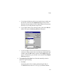
1
The information in this document is believed to be reliable and accurate. However, Xitron Inc.
assumes no contractual responsibility (expressed or implied) for errors which may be present
herein
.
Acrobat and Brilliant Screening are trademarks of Adobe Systems Incorporated.
Alpha is a trademark of Digital Equipment Corporation.
Ethernet is a registered trademark of Xerox Corporation.
Macintosh is a registered trademark of Apple Computer, Incorporated.
InstallShield and UninstallShield are trademarks of the InstallShield Corporation.
PostScript is a registered trademark of Adobe Systems Incorporated.
Windows NT is a registered trademark of Microsoft Corporation.
Copyright © 2000 Xitron Incorporated
Ann Arbor, Michigan USA. All rights reserved
Property of Xitron Incorporated. Confidential material distributed only under license agreement.
Reproduction or use other than as provided in license agreement is prohibited.
Rev
Date
Pages
Text Changes
A
27 January 1999
All
Initial external release; covers
Raster Blaster software release,
version 1.0
B
30 March 2000
All
External release; covers Raster
Blaster software release, version
2.0
C
29 September 2000
All
External release; covers Raster
Blaster software release, version
2.9
D
03 November 2000
All
External release; covers Raster
Blaster software release, version
3.0
iii
iv
Contents
Chapter 1: Introduction
Description . . . . . . . . . . . . . . . . . . . . . . . . . . . . . . . . . . .
A Quick Tour . . . . . . . . . . . . . . . . . . . . . . . . . . . . . . . . .
Chapter 1: Introduction. . . . . . . . . . . . . . . . . . . . . . . .
Chapter 2: Installation . . . . . . . . . . . . . . . . . . . . . . . .
Chapter 3: Removal . . . . . . . . . . . . . . . . . . . . . . . . . .
Chapter 4: Devices. . . . . . . . . . . . . . . . . . . . . . . . . . .
Chapter 5: Queues . . . . . . . . . . . . . . . . . . . . . . . . . . .
Chapter 6: Logs . . . . . . . . . . . . . . . . . . . . . . . . . . . . .
Chapter 7: Operations . . . . . . . . . . . . . . . . . . . . . . . .
Chapter 8: Browser . . . . . . . . . . . . . . . . . . . . . . . . . .
Chapter 9: Connecting . . . . . . . . . . . . . . . . . . . . . . . .
Document Style Conventions. . . . . . . . . . . . . . . . . . . . .
Notes and Cautions . . . . . . . . . . . . . . . . . . . . . . . . . .
Style Conventions Used in Text . . . . . . . . . . . . . . . . .
Related Documents . . . . . . . . . . . . . . . . . . . . . . . . . . . .
Raster Blaster Documentation . . . . . . . . . . . . . . . . . .
On-Disk Supporting Software Documentation . . . . . .
1-1
1-2
1-2
1-2
1-2
1-2
1-3
1-3
1-3
1-3
1-3
1-3
1-4
1-4
1-5
1-5
1-5
Chapter 2: Installation
Before You Begin . . . . . . . . . . . . . . . . . . . . . . . . . . . . . . 2-1
Getting Started . . . . . . . . . . . . . . . . . . . . . . . . . . . . . . . . 2-2
Installing Output Plugins . . . . . . . . . . . . . . . . . . . . . . . . 2-7
The Select Program Folder Wizard Screen . . . . . . . 2-11
Security Key Installation. . . . . . . . . . . . . . . . . . . . . . . . 2-16
Chapter 3: Removal
Remove Your Raster Blaster System Software . . . . . . . 3-1
v
Chapter 4: Devices
Configure Raster Blaster . . . . . . . . . . . . . . . . . . . . . . . . 4-1
Device Configuration Overview . . . . . . . . . . . . . . . . . . . 4-2
Creating New Devices . . . . . . . . . . . . . . . . . . . . . . . . 4-3
Deleting Devices . . . . . . . . . . . . . . . . . . . . . . . . . . . . 4-6
Creating New PSets. . . . . . . . . . . . . . . . . . . . . . . . . . 4-6
Deleting Setups . . . . . . . . . . . . . . . . . . . . . . . . . . . . 4-10
Configuring Device Configuration Tabs . . . . . . . . . . . . 4-11
Default PSet Configurations. . . . . . . . . . . . . . . . . . . 4-13
Device Tab . . . . . . . . . . . . . . . . . . . . . . . . . . . . . . . . 4-14
Imaging Engine group box . . . . . . . . . . . . . . . . . . 4-15
Disable Device check box . . . . . . . . . . . . . . . . . . 4-16
Buffer Size and Band Size spinners . . . . . . . . . . 4-16
Settings Tab . . . . . . . . . . . . . . . . . . . . . . . . . . . . . . . 4-16
Exposure Text Box. . . . . . . . . . . . . . . . . . . . . . . . 4-17
Cassette Menu. . . . . . . . . . . . . . . . . . . . . . . . . . . 4-17
Resolution Menus . . . . . . . . . . . . . . . . . . . . . . . . 4-18
Bottom Portion of Settings Tab . . . . . . . . . . . . . . 4-18
Options Tab . . . . . . . . . . . . . . . . . . . . . . . . . . . . . . . 4-20
Override Option . . . . . . . . . . . . . . . . . . . . . . . . . . 4-21
Orientation Box . . . . . . . . . . . . . . . . . . . . . . . . . . 4-21
Output Copies spinner . . . . . . . . . . . . . . . . . . . . . 4-22
Supply Tab . . . . . . . . . . . . . . . . . . . . . . . . . . . . . . . . 4-23
Configuring Cassettes . . . . . . . . . . . . . . . . . . . . . 4-24
Media Tracking . . . . . . . . . . . . . . . . . . . . . . . . . . 4-24
Assigning Cassettes . . . . . . . . . . . . . . . . . . . . . . 4-26
Enabling Cassette Tracking . . . . . . . . . . . . . . . . . 4-27
Avantra 44 Example Configuration . . . . . . . . . . . 4-28
Takeup Tab . . . . . . . . . . . . . . . . . . . . . . . . . . . . . . . 4-36
Feed Box . . . . . . . . . . . . . . . . . . . . . . . . . . . . . . . 4-36
Wait (Seconds) After Feed Controls . . . . . . . . . . 4-37
Cut Box . . . . . . . . . . . . . . . . . . . . . . . . . . . . . . . . 4-37
vi
Units Menu . . . . . . . . . . . . . . . . . . . . . . . . . . . . . . 4-38
Cut Sheet and Plate Imagers . . . . . . . . . . . . . . . . 4-39
Chapter 5: Queues
Configuring Queues . . . . . . . . . . . . . . . . . . . . . . . . . . . . 5-1
Configuring New Queues . . . . . . . . . . . . . . . . . . . . . . 5-2
Monitor Points . . . . . . . . . . . . . . . . . . . . . . . . . . . . 5-3
Input Monitor Folder . . . . . . . . . . . . . . . . . . . . . . . . 5-3
File Types to Exclude. . . . . . . . . . . . . . . . . . . . . . . 5-8
Maximum Active Pages . . . . . . . . . . . . . . . . . . . . . 5-9
Configuring Thresholds . . . . . . . . . . . . . . . . . . . . 5-10
Editing & Changing Existing Queues . . . . . . . . . . . . 5-11
Deleting Queues . . . . . . . . . . . . . . . . . . . . . . . . . . . 5-13
Sharing a Queue with Macintosh Workstations . . . . 5-15
Chapter 6: Logs
Configure Logs. . . . . . . . . . . . . . . . . . . . . . . . . . . . . . . .
Log Management . . . . . . . . . . . . . . . . . . . . . . . . . . . . . .
Creating a New Log . . . . . . . . . . . . . . . . . . . . . . . . . .
Opening Logs . . . . . . . . . . . . . . . . . . . . . . . . . . . . . . .
Saving Logs As... . . . . . . . . . . . . . . . . . . . . . . . . . . . .
6-1
6-6
6-6
6-6
6-7
Chapter 7: Operations
Starting Your Raster Blaster . . . . . . . . . . . . . . . . . . . . . 7-1
Imaging a File. . . . . . . . . . . . . . . . . . . . . . . . . . . . . . . . . 7-4
Using the Output Monitor . . . . . . . . . . . . . . . . . . . . . . . . 7-6
Job Queue Tabs. . . . . . . . . . . . . . . . . . . . . . . . . . . . . 7-7
Progress Bar . . . . . . . . . . . . . . . . . . . . . . . . . . . . . . . 7-7
Disable Output Check Box . . . . . . . . . . . . . . . . . . . . . 7-8
Job Action Buttons . . . . . . . . . . . . . . . . . . . . . . . . . . . 7-9
Info Button . . . . . . . . . . . . . . . . . . . . . . . . . . . . . . . 7-9
Remove Button . . . . . . . . . . . . . . . . . . . . . . . . . . 7-10
vii
View Button . . . . . . . . . . . . . . . . . . . . . . . . . . . . .
Delete Menu. . . . . . . . . . . . . . . . . . . . . . . . . . . . . . .
Resetting your Raster Blaster . . . . . . . . . . . . . . . . . . .
Shutting Down Your Raster Blaster . . . . . . . . . . . . . . .
7-10
7-14
7-14
7-14
Chapter 8: Browser
Accessing Raster Blaster with a Browser . . . . . . . . . . .
Activity Monitor Tab . . . . . . . . . . . . . . . . . . . . . . . . . . . .
Activity Monitor Subwindows . . . . . . . . . . . . . . . . . . .
Job Information . . . . . . . . . . . . . . . . . . . . . . . . . . . . .
Detachable Copies of the Four SubWindows . . . . . .
Progress Bar . . . . . . . . . . . . . . . . . . . . . . . . . . . . . . .
8-1
8-3
8-4
8-5
8-6
8-7
Chapter 9: Connecting
Preparing Raster Blaster for TIFF Output . . . . . . . . . . .
Creating a Shared Directory. . . . . . . . . . . . . . . . . . . .
Preparing the RIP . . . . . . . . . . . . . . . . . . . . . . . . . . . . .
Mapping a Raster Blaster drive to the Xitron RIP . . .
Configuring the RIP for TIFF Output . . . . . . . . . . . . . . .
Glossary
Index
viii
9-1
9-2
9-4
9-4
9-6
. . . . . . . . . . . . . . . . . . . . . . . . . . . . Glossary-1
. . . . . . . . . . . . . . . . . . . . . . . . . . . . . . . . . . . Index-1
Chapter 1: Introduction
Description
Raster Blaster is a Xitron software system for imaging bitmaps.
Raster Blaster accepts screened black and white TIFF files in 1-bit/multiple
strips, 2-bit/multiple strips, 1-bit/single strip formats, as well as a number
of compression schemes including: CCITT Group3, CCITT Group4,
CCITT Huffman, LZW, and Packbits, and outputs these files as pre-rasterized images to a wide number of imagesetters.
Raster Blaster operates using the Windows NT operating system in unit
and symmetrical multi-processor (SMP) configurations.
• You can configure, monitor, and operate Raster Blaster through its
menu-driven graphic user interface, using the computer on which it is
installed.
• You can remotely monitor the operation of the Raster Blaster and get
information about the jobs that Raster Blaster is processing through its
browser interface.
1-1
Raster Blaster User’s Guide
A Quick Tour
This user’s guide contains nine chapters, a glossary and an index:
Chapter 1: Introduction
This chapter includes:
• A description of Raster Blaster.
• The contents of this guide.
• An explanation of style conventions used in this guide.
• A list of related documents.
Chapter 2: Installation
This chapter includes installation instructions for the Raster Blaster software and Raster Blaster output plugins.
Chapter 3: Removal
This chapter describes how to remove Raster Blaster and any output plugins you may have installed.
Chapter 4: Devices
This chapter describes how to configure the core of Raster Blaster, its
output devices and their associated parameter sets (PSets).
1-2
Introduction
Chapter 5: Queues
This chapter describes how to configure input queues for sending files to
Raster Blaster.
Chapter 6: Logs
This chapter describes how to configure and manage your system logs.
Chapter 7: Operations
This chapter describes various operating tasks, including starting, imaging
files, resetting and shutting down Raster Blaster.
Chapter 8: Browser
This chapter describes the monitoring that can be performed through a
browser on the host system or a remote computer.
Chapter 9: Connecting
This chapter describes the process of connecting Raster Blaster to Xitron’s
Navigator NT RIP.
Document Style Conventions
This document contains a number of style conventions designed to make it
easier to use.
1-3
Raster Blaster User’s Guide
Notes and Cautions
Notes and Cautions appear within horizontal rules and are used for the following purposes:
Note: Notes provide information that is important enough to
demand special attention. The information may be relevant to the
current discussion but awkward to include without disrupting the
flow of information.
CAUTION
Cautions advise of situations that might cause equipment damage
or loss of information or work time.
Style Conventions Used in Text
A change of typeface within the document indicates such things as screen
messages and operator entries. The following conventions are used:
Italic
designates file names, directories, variables, and document
references (for example, “the Hosts file...”).
Bold
designates text entered by the operator using the keyboard
(for example: “Enter 1111 for the directory”).
Bold italic
designates entries found on the screen (for example: “click
the Configure button”).
Extended blocks of text found on-screen are placed in separate paragraphs,
which use a smaller type size and have special indents (as shown in the following example:
1-4
Introduction
This example represents an extended block of text captured from the
screen. The point size is slightly smaller, and the left and right margins
have been indented slightly.
Related Documents
The following documents are available to assist in the use of Raster
Blaster:
Raster Blaster Documentation
A copy of the Raster Blaster User’s Guide is provided with each1 Raster
Blaster on the CD ROM disk.
On-Disk Supporting Software Documentation
The following supporting software elements are provided on the Raster
Blaster CD-ROM disk:
•
Raster Blaster Output Plugins
1. A
copy of this document in Acrobat pdf form can be found in the Documentation
folder on the Raster Blaster compact disc.
1-5
Raster Blaster User’s Guide
1-6
Chapter 2: Installation
Before You Begin
Raster Blaster software is designed to run by itself on a dedicated
computer. Do not install other applications or utilities beyond those needed
for system operation. Unneeded utilities and applications may interfere
with the functioning of the Raster Blaster program and cause it to lose communications with the attached output imager.
• Windows NT 4.0 Service Pack 5 must be installed on your computer
before you install the Raster Blaster program. Other versions of Windows NT may create problems with AppleTalk networking. To make
sure that all necessary changes to the System software have been correctly applied, it is a good idea to run the Service pack both before and
after all installation procedures are completed.
• Before installing Raster Blaster, make sure you have the desired network
services installed.
• If you want to run the browser interface on your local machine, you
must install Microsoft Internet Explorer (revision 4.0 or later) on your
local machine.
2-1
Raster Blaster User’s Guide
• If you want to run the browser interface on your local machine, and you
are running Raster Blaster on a platform with Windows NT Workstation
installed, you must install Microsoft Peer Web Services on the computer
where Raster Blaster resides.
• If you want to run the browser interface on your local machine, and you
are running on a platform with Windows NT Server installed, you must
install the Internet Information Server (IIS) on the computer where Raster Blaster resides.
Getting Started
1. Log in to Windows NT as a user with administrator privileges.
2. Insert the Raster Blaster compact disk in the CD drive of the computer you want to use as your Raster Blaster platform.
3. The installation program checks to see if all the necessary system
files are in place on your computer. If all the system files are there,
the next screen you see is the Raster Blaster splash screen. In this
case, skip ahead to step 9 on page 2-4.
If you don’t see the Raster Blaster splash screen at this point, continue
with step 4 below.
2-2
Installation
4. If the installation program finds some important system files missing,
it will display the following dialog box:
5. If you see this message box, click Yes to automatically reboot your
computer and continue with the installation.
6. When you click Yes, the installation program installs the missing files
and reboots your computer to make the new system files available.
7. Now start the installation procedure over again by removing the Raster Blaster compact disk from the CD drive and reinserting it, or
Auto-start your CD drive by double clicking the appropriate drive
icon in the My Computer window.
8. When you Auto-start the installation CD, the Raster Blaster splash
screen appears.
2-3
Raster Blaster User’s Guide
9. To start installing Raster Blaster, click Install RIP. A progress bar
appears to indicate that the InstallShield Wizard is being initiated.
After the progress bar is filled, the Welcome screen appears.
2-4
Installation
10. Click Next on the Welcome screen to continue.
The Choose Destination Location wizard screen appears, asking you to
define the name and location of the folder in which the Raster Blaster software will be installed.
Choose Destination Location wizard screen
Note: The suggested Destination Folder will be located on the
NTFS formatted partition of your hard drive.
2-5
Raster Blaster User’s Guide
11. To accept the suggested Destination Folder, click Next to continue.
To change the location for your Raster Blaster software, perform the
following lettered steps:
a. Click Browse.
b. Using standard Windows techniques, select the desired location
in the Directory Browser that appears.
c. Click OK. The Directory Browser closes and the Choose Destination Location wizard screen returns with the location you
selected displayed as the Destination Folder.
d. Click Next to continue.
The Select Components wizard screen appears.
Select Components wizard screen
2-6
Installation
At this point, you may complete your installation without installing Output
Plugins by clicking Next and skipping ahead to “The Select Program
Folder Wizard Screen” on page 2-11.
To load Output Plugins now, continue with the next section.
Installing Output Plugins
Raster Blaster Output Plugins allow users of Raster Blaster to send output
to Xitron supported imagers. Output Plugins provide imager-specific data
to the Device Setup dialog box. To load the appropriate Output PlugIn for
your imager, follow these steps:
Select Components wizard screen
2-7
Raster Blaster User’s Guide
1. On the Select Components screen, highlight the line that says:
Output Device Files - Select Output Device
2. Click Change.
The Select Sub-components dialog box appears, containing a menu of Output Plugins.
Select Sub-components wizard screen
2-8
Installation
3. Scroll through the list, choose the appropriate PlugIn and select it by
clicking in the box to the left of the plugin name. Be sure not to deselect the item called Diag + Utilities. Click the Continue button to go
back to the Select Components screen. Click Next to continue with
the installation.
The next screen to appear depends on which output plugins you
selected from the list on the Select Sub-components screen.
You will see the Select Program Folder wizard screen if you selected one
of the following:
•
•
•
•
Barco Output Plugin and Drivers
Bitmap Output Plugin
Celix Output Plugin and Drivers
Screen FTR Output Plugin and Drivers
If you selected one of these plugins, skip ahead to “The Select Program
Folder Wizard Screen” on page 2-11.
If you selected any other device plugin, the next screen to appear is the I/O
base for the personality card wizard screen. This screen asks you to select
the I/O base address for the PB2 card you are using.
2-9
Raster Blaster User’s Guide
Note: Note, with our new single board PCI cards you will not see
this screen for any of our plugins. The single board PCI card is just
coming into production as of this writing, and is not being widely
shipped yet.
I/O base for the personality card wizard screen
4. Make your selection for I/O base address, and click Next.
The next screen is the Select Program Folder wizard screen.
2-10
Installation
The Select Program Folder Wizard Screen
The Select Program Folder wizard screen asks you to choose a name for
the program folder in which the icons for elements of the Raster Blaster
system software will be installed.
Select Program Folder wizard screen
1. Select the appropriate folder name and click Next.
2-11
Raster Blaster User’s Guide
The Start Copying Files wizard screen appears.
Start Copying Files wizard screen
2. Click Next to begin copying files.
2-12
Installation
Files are copied into your computer, as indicated by the appearance of a
title window and progress bar showing the percent of the installation that
has been completed:
Title window and progress bar
When the progress bar reaches 100%, the next screen appears, indicating
successful installation.
2-13
Raster Blaster User’s Guide
Next, the InstallShield Wizard Complete screen appears.
InstallShield Wizard Complete screen
3. Select the Yes button, and click Finish to complete your Raster
Blaster system installation.
Your Raster Blaster computer shuts down and restarts.
2-14
Installation
After installation, Raster Blaster and Modular Installer appear as Start
menu commands.
Start Menu Commands for Raster Blaster
2-15
Raster Blaster User’s Guide
Also, the Raster Blaster icon appears on your desktop:
If you didn’t install Output PlugIns, you may do it now (refer to “Installing
Output Plugins” on page 2-7).
Security Key Installation
Raster Blaster is equipped with a security key that must be installed to
enable the software.
CAUTION
Remove power from your Raster Blaster computer whenever you
install, remove, or replace the security key (dongle). Otherwise,
you may damage your computer.
The security key (also known as the dongle) plugs into the parallel port of
the computer where Raster Blaster resides. The dongle must be installed
for Raster Blaster to work. The security key is a feed-through device. If you
need to connect a cable to your parallel port, you can connect it to the
installed security key, just as if it were the parallel connector. You are now
ready to start using Raster Blaster.
2-16
Chapter 3: Removal
You do not need any compact disk or floppy disk to perform any of the procedures in this chapter.
Remove Your Raster Blaster System
Software
All software removal procedures involve the use of the UninstallShield
utility, activated through the Add/Remove Programs icon in the Control
Panel window.
Note: The Raster Blaster removal procedure does not delete definitions for devices or PSets. These definitions remain in the Registry.
1. Make sure that your Raster Blaster system is not running.
3-1
Raster Blaster User’s Guide
2. From the Start menu, point to Settings and click Control Panel.
3-2
Removal
3. In the Control Panel window, double-click the Add/Remove Programs icon.
Control Panel window
3-3
Raster Blaster User’s Guide
4. If not already selected, select the Install/Uninstall tab in the Add/
Remove Programs Properties dialog box that appears.
Add/Remove Programs Properties dialog box
5. To remove the Raster Blaster system, select it from the list in the Add/
Remove Programs Properties dialog box and click Add/Remove.
3-4
Removal
6. Click Yes in the Confirmation dialog box to confirm your intention to
remove your Raster Blaster system software.
Confirmation dialog box
7. The UninstallShield utility begins, as shown by the Setup Status wizard screen.
Setup Status wizard screen
3-5
Raster Blaster User’s Guide
8. When the UninstallShield utility finishes, as indicated by the completed progress bar, the following information box appears:
Information box
9. Click OK to close the box.
10. Shut down and restart your computer.
11. You have finished removing your Raster Blaster system software.
3-6
Chapter 4: Devices
Configure Raster Blaster
The menu selection File > Configure Raster Blaster displays a screen for
setting advanced features of Raster Blaster not available in this release.
4-1
Raster Blaster User’s Guide
Device Configuration Overview
This is the first of two configuration chapters. The Device Configuration
dialog box is the main focus of our configuration efforts in this chapter. In
the next chapter we will focus on configuring queues for inputting files into
Raster Blaster.
The devices you configure determine which imagers you can use for output. For each device, you can also define parameter sets (PSets) which
determine how the selected imager will process the output. By selecting an
output device and one of that device’s PSets, you determine which imager
receives the output and how it processes that output.
This section is divided into two main parts:
• First, we cover the Device Configuration dialog box and how to create
or delete new devices and PSets).
• Next, we cover the configuration of each of the tabs in the Device Configuration dialog box (refer to “Configuring Device Configuration
Tabs” on page 4-11).
Note: To help put these configuration efforts in context, the discussion includes an example configuration for an Agfa Avantra 44
(refer to “Avantra 44 Example Configuration” on page 4-28).
4-2
Devices
Creating New Devices
To create a new device, follow the steps below:
1. Open the Device Configuration dialog box by pulling the File menu
down to Configure Devices.
The Device Configuration dialog box has up to five tabs that allow
you to configure devices and parameter sets (PSets). A different subset of tabs is involved in these two configuration tasks. When you
highlight a device, five tabs appear as shown here:
Device Configuration dialog box
Note: If the PSets for a device are displayed in the Output Devices
list, you can hide them by double-clicking on the device icon. If
they are already hidden, double-click the device icon to display
them. After you add a new PSet, all PSets for that device are displayed.
4-3
Raster Blaster User’s Guide
2. To configure a new device, click the New Device button.
3. The Add New Device dialog box appears.
Add New Device dialog box.
4. From the Driver pop-up menu, select the driver for your output
device.
5. If you choose a device with more than one type, the Type pop-up
menu will become active. It lists the available device types that apply
to the selected Driver.
6. Select the appropriate device from the Type pop-up menu.
7. Your system labels the device you are creating in the Name text box.
The label used consists of a shorthand reference to the selected
device, followed by a dash and a number. For example, Raster Blaster
labels an Avantra 44 device being created as Avantra 44-0. The number increases as you create additional devices (Avantra 44-1, Avantra
44-2, and so forth).
8. Most devices will have additional options that are configured using
the Driver Config button. See the plugin manual for instructions on
these additional configuration settings.
9. The Address text box and button are not used in this version of Raster
Blaster.
4-4
Devices
10. Click OK. The Add New Device dialog box closes. The device you
created appears in the Output Devices window of the Device Configuration dialog box. Also, the configuration choices you have made so
far appear under the Device parameter tab. Click the Save button on
the Device Configuration dialog box to save the new device.
Device Configuration dialog box
Note: By configuring a device, you have also configured the
default PSet for that device.
11. To configure the parameter tabs for the device you just added, refer to
“Configuring Device Configuration Tabs” on page 4-11.
12. To delete devices, refer to “Deleting Devices” on page 4-6 .
4-5
Raster Blaster User’s Guide
Deleting Devices
To delete a device and all of its PSets:
1. Highlight the device icon in the Output Devices window of the
Device Configuration dialog box.
2. On your keyboard, press the Delete key.
3. When asked to confirm your intention to delete the selected device
and all of its PSets, click Yes.
Confirmation message box
Creating New PSets
Note: Each new PSet will inherit the default PSet configuration of
its device. Refer to “Configuring Device Configuration Tabs” on
page 4-11 for device and PSet configuration information.
To create a new parameter set (PSet):
1. In the Output Devices window of the Device Configuration dialog
box, highlight the device for which you want to create a PSet.
4-6
Devices
2. In the lower right corner of the Device Configuration dialog box,
click New PSet. The Add New Setup dialog box appears.
3. Select a Setup Name.
a. If you want to use a numeric name for your PSet, perform the following substeps. If, instead, you want to use a non-numeric name
for your PSet, skip ahead to step b.
(1) Deselect the Allow non-numeric setup names box to give
the P-Set a numeric setup name. The Add New Setup dialog
box is displayed as shown below.
Add New Setup dialog box
(2) Enter a number in the PSet window. The default value is 1.
The default value automatically increases for subsequent
PSets for the same device.
(3) To accept your configuration entries, click OK.
4-7
Raster Blaster User’s Guide
Note: If you deselected the Allow non-numeric setup names box
and clicked OK, your system must change from alpha PSet naming
to numeric. To accept the change in PSet naming, click Yes in the
following message box.
Confirmation message box
(4) Skip ahead to step 4 on page 4-9.
b. To give your PSet a non-numeric name, perform the following
substeps:
(1) Select Allow non-numeric setup names by clicking in the
box next to it.
Add New Setup dialog box
(2) Enter a name in the Setup Name text box. The default name
is PSet n (where n is the next default PSet number).
4-8
Devices
Note: In the default non-numeric default PSet name, two spaces
are placed between the word PSet and a single digit number.
(3) To accept your configuration entries, click OK.
Note: If you selected Allow non-numeric setup names and clicked
OK, your system must change from numeric PSet naming to alpha.
To accept the change in PSet naming, click Yes in the following
message box.
Confirmation message box
4. When you click Yes to close the message box, the Add New Setup
dialog box closes.
4-9
Raster Blaster User’s Guide
5. The PSet you created appears in the Output Devices window of the
Device Configuration dialog box.
Device Configuration dialog box
6. To configure the PSet you just added, refer to “Configuring Device
Configuration Tabs” on page 4-11.
7. To delete PSets, refer to “Deleting Setups” below.
Deleting Setups
To delete a PSet:
1. Highlight the PSet icon in the Output Devices window of the Device
Configuration dialog box.
2. On your keyboard, press the Delete key.
4-10
Devices
3. When asked to confirm your intention to delete the selected PSet,
click Yes.
Confirmation message box
Configuring Device Configuration Tabs
The Device Configuration dialog box choices are divided into a series of
up to five parameter tabs. If a device name is highlighted in the Output
Devices window of the Device Configuration dialog box, up to five tabs
are displayed. If a PSet name is highlighted instead, two tabs are displayed.
An example of the dialog box in both forms is shown on page 4-12.
4-11
Raster Blaster User’s Guide
Device Configuration dialog box, Device name highlighted
Device Configuration dialog box, PSet name highlighted
4-12
Devices
Device Configuration dialog box parameter tabs are described in the following topics:
• “Default PSet Configurations” on page 4-13.
• “Device Tab” on page 4-14.
• “Settings Tab” on page 4-16.
• “Options Tab” on page 4-20.
• “Supply Tab” on page 4-23.
• “Takeup Tab” on page 4-36.
Default PSet Configurations
If you do not create any PSets for a device, the device configuration for the
Settings and Options parameter tabs collectively become the default PSet
configuration.
Further, when you create a new PSet, you begin with the default PSet configuration. You can then tailor the new PSet to your specific requirements
by changing the configuration of the parameter tabs that appear.
You can also reconfigure an existing PSet by highlighting its name and
changing the configuration of the parameter tabs that appear.
Note: In order to ensure that all of the TIFF files are imaged at the
correct resolution, you must create a PSet for each resolution
required.
4-13
Raster Blaster User’s Guide
Device Tab
Note: When configuring devices or PSets for the first time, configure the tabs in order from left to right starting with the Device tab.
Remember that the Device Tab is one of the tabs that does not
appear when you configure PSets.
The Device tab displays information about the device you have highlighted
in the Output Devices window. As shown below by the sample Device tab
for an Avantra 44 device, the Device tab contains information about the
device that you configured when the device was first created. The Location
text box is new, however. It allows you to record your own descriptive
comment about the selected device.
4-14
Devices
Device Configuration dialog box, Device Tab
Imaging Engine group box
The Imaging Engine group box displays information about the selected
device.
• Type displays the generic category of the selected imager (Capstan, CutSheet, Drum, Plate Setter, or none).
• Max. Width refers to the fast scan direction of the imager.
• Max. Height refers to the slow scan direction, if any.
• Units This menu sets the units for the Max. Width and Max. Height
entries (menu choices are Inches, Picas, Millimeters or Points).
4-15
Raster Blaster User’s Guide
Disable Device check box
Select Disable Device only if you want to prevent jobs from being processed by the selected device. Otherwise, clear it.
Buffer Size and Band Size spinners
The displayed values are defaults chosen by your Raster Blaster system.
Change them only on advice from Xitron technical support.
Settings Tab
Settings Tab
4-16
Devices
Note: When a device name is highlighted in the Output Devices
window, the settings in the Settings tab along with the settings in
the Options tab determine the default configuration for any new
PSets. On the other hand, when a PSet name is highlighted, these
settings determine the specific configuration for the highlighted
PSet.
Click on the Settings tab:
The Settings tab contains the following parameters:
Exposure Text Box
Note: For imagers that do not allow Raster Blaster to control laser
intensity, Exposure is unavailable.
For imagers that allow Raster Blaster to control laser intensity, enter the
desired intensity in Exposure.
Cassette Menu
Note: If you have unchecked Disable Cassette Tracking in the
Supply tab and you do not select one of the cassettes assigned to
the selected device and PSet, your Raster Blaster system will post
an error message.
Select one of 16 cassettes. Refer to “Supply Tab” on page 4-23 for instructions on configuring or assigning cassettes. If the cassette you select is
assigned to a station or tray, the job will be imaged to that station or tray.
4-17
Raster Blaster User’s Guide
Resolution Menus
The entries on the Vertical and Horizontal menus represent the allowable
resolution settings for the selected device.
For most devices, you must select the same Vertical and Horizontal entries.
If you select a value in the Vertical menu, the corresponding value automatically appears in the Horizontal menu and vice versa.
However, for some imagers, you can select different values for the Vertical
menu and the Horizontal menu.
If you select a value in the Horizontal menu, the corresponding value
automatically appears in the Vertical menu.
However, if you select a value in the Vertical menu, the Horizontal
menu retains its original value.
Bottom Portion of Settings Tab
The remaining items include:
• The Width, Length, and Type entries for Media are determined by the
selected Cassette.
• The Width and Length entries for Device are determined by the highlighted device in the Output Device list.
• The Margins box specifies measurements that are graphically illustrated
in the diagram to its right. This diagram changes depending on the type
of device that is highlighted, as shown in the three separate illustrations
on page 4-19.
4-18
Devices
• The Units menu specifies the units of measurement for the Width and
Length items and the entries in the Margins box, Choices are Inches,
MilliMeters, Picas, and Points.
Settings Diagram for Capstan Imagers
Settings Diagram for Cut Sheet Imagers
Settings Diagram for Drum Imagers
4-19
Raster Blaster User’s Guide
Options Tab
Note: When a device name is highlighted in the Output Devices
window, the settings in the Options tab along with the settings in
the Settings tab determine the default configuration for new PSets.
On the other hand, when a PSet icon is highlighted instead, the settings apply to the highlighted PSet.
The Options tab includes an Override option, the Orientation group box,
and the Output Copies spinner.
Options Tab
4-20
Devices
Override Option
Check the Override Job Resolution box if you want your Vertical and Horizontal Resolution entries configured in the Settings Tab to override the
resolution settings contained in the job.
Clear the Override Job Resolution box if you want the resolution settings
contained in the job to apply.
Orientation Box
1. Check the Center on Media Width box if you want to center the
image along the width of the output media.
2. Check the Center on Media Length box if you want to center the
image along the length of the output media.
Note: The results of the remaining items in the Orientation box are
illustrated through the icon containing the capital “A”. For example, the illustration below shows how the output would change if
you selected Image Negate, and cleared Margin Negate.
Orientation box in Options Tab
4-21
Raster Blaster User’s Guide
3. Select Image Negate if you want to create a negative image of the job
being processed. When you do, the Margin Negate check box
becomes available and selected.
4. Clear Image Negate for a positive image and to make the Margin
Negate check box unavailable.
5. Clear Margin Negate if you want to create a negative image of only
the image, not the margins.
6. Select Wrong Read if you want the image to appear backwards, as if
viewed in a mirror.
Output Copies spinner
Select the number of copies you want to output with the Output Copies
spinner.
4-22
Devices
Supply Tab
Supply Tab
Supply tab configuration is divided into the following topics:
• “Configuring Cassettes” on page 4-24.
• “Media Tracking” on page 4-24.
• “Assigning Cassettes” on page 4-26.
• “Enabling Cassette Tracking” on page 4-27.
• “Avantra 44 Example Configuration” on page 4-28.
Note: “Avantra 44 Example Configuration” provides an example
procedure in which cassettes are configured and assigned.
4-23
Raster Blaster User’s Guide
Configuring Cassettes
Note: Each device has its own complement of 16 cassettes. You
must configure the cassettes for each device separately.
To configure a cassette:
1. Highlight one of the 16 cassettes in the Cassettes window.
2. In the Media Type text box, enter a descriptive comment about the
media stored in the selected cassette, such as “Film”, “paper”, or the
part number of the type of film being used.
3. Enter the Media Width value.
4. For cut sheet or plate imagers, enter the Media Height value.
5. Select the units of measurement for the Media Width, Media Height,
and Thickness entries from the Units menu. Choices are Inches,
Millimeters, and Centimeters.
6. For plate imagers, enter the Thickness value for the plate media. For
non-plate imagers, Thickness is unavailable.
Media Tracking
To enable media tracking, allowing your Raster Blaster system to keep
track of the media available in the cassettes you configure:
1. Deselect Disable Media Tracking box.
2. For roll-fed media, the remaining media tracking controls include:
a. Roll Length text box.
b. Units menu to the immediate right of Roll Length. Menu choices
for Units are Feet or Meters. The unit you select applies to the
Roll Length text box and Warn at window.
4-24
Devices
c. Warn at check box and window
3. For plate media, the Roll Length text box changes to Plate Count, the
Units menu becomes unavailable, and the Warn at window value is
expressed in plates.
Supply Tab
4-25
Raster Blaster User’s Guide
4. For cut sheet media, the Roll Length text box changes to Sheet
Count, the Units menu becomes unavailable, and the Warn at
window value is expressed in sheets.
Assigning Cassettes
To assign cassettes to imager stations:
1. From the Stations window, highlight the Slot to which you wish to
assign a cassette.
2. From the Cassettes window, highlight the desired cassette.
4-26
Devices
3. Click » to assign the highlighted cassette to the highlighted station.
The selected Cassette no longer appears in the Cassettes window but
instead now appears in the Stations window under the selected Slot.
Supply Tab
4. Repeat until you have assigned cassettes to all the imager stations.
5. To unassign a cassette:
a. Highlight the assigned cassette in the Stations window.
b. Click « to return the highlighted cassette to the Cassettes window, removing it from the Stations window.
Enabling Cassette Tracking
Deselect the Disable Cassette Tracking box to enable cassette tracking.
Refer to “Cassette Menu” on page 4-17, under the description of the Settings parameter tab, for more information.
4-27
Raster Blaster User’s Guide
Avantra 44 Example Configuration
This procedure demonstrates how to configure selected aspects of an
Avantra 44 printer. It is intended to serve as an example of the various controls involved in cassette and tray configuration.
Although it involves many different controls and dialog boxes, this procedure is located here, in the heart of the Supply parameter tab description,
because of the unusual way cassettes are configured and assigned to stations in the Supply parameter tab.
The procedure is divided into the following tasks:
• “Create a new device for the Avantra 44.” Refer to step 1 on page 4-28.
• “Configure the Supply parameter tab for the Avantra 44.” Refer to step 2
on page 4-30.
• “Create new PSets for your Avantra 44. This example will demonstrate
creating two Psets. One will be 2400dpi negative and the other will be
2400dpi positive.” Refer to step 3 on page 4-31.
• “Configure the Settings tab for the new PSets associated with your new
Avantra 44.” Refer to step 4 on page 4-32.
• “Configure the Options parameter tab for each of the PSets associated
with your Avantra 44.” Refer to step 5 on page 4-34.
Note: The following procedure does not represent a complete configuration of an Avantra 44. Instead, it concentrates on those steps
related to cassette configuration and assignment.
1. Create a new device for the Avantra 44.
4-28
Devices
a. If the Device Configuration dialog box is not already present,
start by selecting Configure Raster Blaster from the File menu
of the Raster Blaster log window. The Device Configuration dialog box appears.
b. Click New Device. The Add New Device dialog box appears.
Add New Device dialog box
c. If it is not already selected, select Agfa from the Driver menu.
d. Select Avantra 44 from the Type menu.
e. Click OK. The Add New Device dialog box closes.
f. The Device name you created appears in the Output Devices window of the Device Configuration dialog box.
4-29
Raster Blaster User’s Guide
Device Configuration dialog box
2. Configure the Supply parameter tab for the Avantra 44.
a. With Avantra 44-0 still selected in the Output Devices window,
click the Supply parameter tab. The Supply tab is displayed.
Supply Tab
b. If not already highlighted, click the Cassette 1 icon in the
Cassettes window to highlight it.
c. Click the Slot A icon in the Stations window to highlight it.
4-30
Devices
d. Click » to move the Cassette 1 icon under the Slot A icon in the
Stations window.
e. With Cassette 1 under Slot A in the Stations window and still
highlighted, configure the media for the upper tray.
Supply Tab
(1) Update the value in the Media Width text box if it differs
from the material in the cassette.
3. Create new PSets for your Avantra 44. This example will demonstrate
creating two Psets. One will be 2400dpi negative and the other will be
2400dpi positive.
4-31
Raster Blaster User’s Guide
a. With the Avantra 44-0 icon still selected, click New PSet. The
Add New Setup dialog box appears.
Add New Setup dialog box
(1) Select Allow non-numeric setup names, if necessary.
(2) Enter 2400dpi Neg in the Setup Name text box.
(3) Click OK. The Add New Setup dialog box closes. The
2400dpi Neg PSet icon appears under Avantra 44-0 in the
Output Devices window.
b. Click New PSet again. The Add New Setup dialog box appears.
(1) Enter 2400dpi Pos in the Setup Name text box.
(2) Click OK. The Add New Setup dialog box closes.The
2400dpi Pos PSet name appears under Avantra 44-0.
4. Configure the Settings tab for the new PSets associated with your
new Avantra 44.
a. Highlight the 2400dpi Neg PSet icon under Avantra 44-0 in the
Output Devices window.
(1) Click the Settings parameter tab.
(2) Set the resolution to 2400.
4-32
Devices
Settings Tab
(3) Configure the remaining entries in the Settings parameter
tab as desired.
b. Highlight the 2400dpi Pos PSet icon under Avantra 44-0.
(1) Set the resolution to 2400.
4-33
Raster Blaster User’s Guide
Settings Tab
(2) Configure the remaining entries in the Settings parameter
tab as desired.
5. Configure the Options parameter tab for each of the PSets associated
with your Avantra 44.
a. Click the Options parameter tab in the Device Configuration dialog box.
b. Highlight the 2400dpi Neg PSet under Avantra 44-0 in the Output Devices window.
4-34
Devices
Options Tab
(1) In the Orientation box, check the Image Negate box.
(2) Configure the remaining entries in the Options tab.
c. Highlight the 2400dpi Pos PSet in the Output Devices window.
(1) In the Orientation box, deselect the Image Negate box, if
necessary.
(2) Configure the remaining entries in the Options tab.
To move on to the next section, select a device name from the Output
Devices window at the left side of the Device Configuration dialog box.
This makes the Takeup Tab available.
4-35
Raster Blaster User’s Guide
Takeup Tab
For roll-fed devices, the Takeup tab allows you to control the amount of
media the imager feeds between pages and between jobs, the time you wait
after each feed, and a variety of cut controls.
Takeup Tab
Feed Box
• Select the Between pages check box to make its text box available.
Enter the desired amount of media to be fed between pages in its text
box.
Note: The Between pages and Between jobs configuration controls
operate independently of each other.
• Select the Between jobs check box to make its text box available. Enter
the desired amount of media to be fed between jobs in its text box.
4-36
Devices
Note: Adjust per feed does not exercise any control over the
imager but serves instead to keep a record of the media movement.
This field allows your system to keep track of media usage more
accurately. You must have cleared Disable Media Tracking in the
Supply tab. Refer to “Media Tracking” on page 4-24.
• Enter the fixed amount that the imager moves the media after each feed
in the Adjust per feed text box.
Wait (Seconds) After Feed Controls
Select Wait (seconds) after feed to make its text box available. Enter the
number of seconds you want your imager to wait after a feed before it
becomes available for the next job.
Cut Box
Note: The Cut box applies only to imagers with an online processor (OLP) or darkroom adapter (DRA).The Units menu at the bottom of the Takeup tab dialog box specifies the units of
measurement for all of the Cut box text boxes.
• Select After job to enable cuts after each job.
Note: The After job and After pages check boxes operate independently of each other.
• Select After pages to make its spinner available. Enter the number of
pages you want to process before each cut.
4-37
Raster Blaster User’s Guide
• Select Min. before cut to make available its text box. Enter the minimum amount of media you want exposed before each cut.
• Select Max. before cut to make available its text box. Enter the maximum amount of media you want exposed before each cut.
Note: Adjust per cut does not exercise any control over the imager
but serves instead as a record of the entered value. This field
allows your Raster Blaster system to keep track of media usage
more accurately. You must have cleared Disable Media Tracking
in the Supply tab. Refer to “Media Tracking” on page 4-24.
• Enter the fixed amount that the imager moves the media for each cut in
the Adjust per cut text box.
Units Menu
Select the units of measurement for the Feed and Cut text boxes from the
Units menu. Menu choices are inches, feet, and meters.
4-38
Devices
Cut Sheet and Plate Imagers
As shown below, only the Wait (seconds) after feed controls are available
for cut sheet and plate imagers.
Takeup Tab
4-39
Raster Blaster User’s Guide
4-40
Chapter 5: Queues
Configuring Queues
To ensure that the TIFF files coming into Raster Blaster are imaged at the
correct resolution, you need to configure a unique queue for each resolution value supported by the output device attached to Raster Blaster’s interface. This chapter gives instructions for configuring these queues. The
chapter is divided into the following parts:
• “Configuring New Queues” on page 5-2.
• “Editing & Changing Existing Queues” on page 5-11.
• “Deleting Queues” on page 5-13.
• “Sharing a Queue with Macintosh Workstations” on page 5-15.
5-1
Raster Blaster User’s Guide
Configuring New Queues
It is a good idea to have all your Raster Blaster input queues folders setup
within one directory. This keeps your queue records more organized than
having queue folders in various places in your computer. This also makes it
easier to connect to your queues across the network from your RIP. Refer to
“Creating a Shared Directory” on page 9-2.
1. To configure new queues, select Configure Queue from the File
menu of the Raster Blaster log window. The Configure Queue dialog
box appears.
Configure Queue dialog box
When this dialog box opens for the first time, a queue directory called
‘\PAGEBUFF\’ appears in the Queue Folder pop-up menu. Leave
5-2
Queues
this entry in the Queue Folder text box -- do not delete it. The PAGEBUFF directory is the folder where jobs enter Raster Blaster and
where sub-folders are created for storing jobs either waiting to output
or already output.
Monitor Points
Monitor Points are the queue folders that you configure to control the handling of jobs input to Raster Blaster. Each folder refers to a specific input
queue. The check box next to each folder name allows you to make that
queue active when Raster Blaster is running. The focus of your efforts in
configuring new queues and changing or deleting existing queues is the
section of the Configure Queue dialog box labeled Monitor Points. This
section contains a list of the existing monitor folders and their parameters.
It also contains buttons for Adding, Deleting and Editing monitor folders.
2. To configure a new queue folder, click the Add Monitor button. The
Input Monitor Folder dialog box appears.
Input Monitor Folder
The Input Monitor Folder dialog box allows you to name a queue
folder and specify how to handle files that arrive as input to Raster
Blaster in that specific queue folder.
5-3
Raster Blaster User’s Guide
3. Do one of the following:
a. If you know the directory for this queue folder, type that directory
name into the Folder text box. If the directory you type in does
not exist, Raster Blaster will create the directory for you. Skip
ahead to step 4 on page 5-7 to complete the dialog box.
b. If you want to browse for a directory name, click on the square
button with three dots ‘...’ to the right of the Folder text box. This
opens the Browse for Folder dialog box.
5-4
Queues
Browse for Folder dialog box
Use this dialog box to locate and select the directory you wish to
specify. When you have the correct directory displayed in this window, click the New Folder button. This opens the New Folder dialog
box.
5-5
Raster Blaster User’s Guide
(1) Type the name of the new queue folder in the New Folder
Name text box, and click OK to return to the Browse for
Folder dialog box. Your new folder name appears in the
directory you selected.
(2) Click OK to close the Browse for Folder dialog box. Your
new folder name appears in the Folder text box of the Input
Monitor Folder dialog box.
5-6
Queues
4. Follow the steps below to complete the parameters on the Input Monitor Folder dialog box:
5. Under Default Output Device, select your Device and Pset.
6. Put a check mark in the Always use Device and PSet associated with
Queue check box if the Device and PSet selected here should be used
even when the incoming file contains device and PSet information.
Note: If a job is not associated with a device, it will appear in the
Active queue, but it will not be processed.
7. Checking Override Device under Orientation allows you to override
the orientation setting configured for the Device/PSet. When you
check Override Device, the Rotation text box and Wrong Read check
box become available.
Rotation for the queue may be set to 0, 90, 180, or 270 degrees, or
select To Fit (+90) or To Fit (-90).
Checking Wrong Read flips the incoming file to Wrong Read mode
before output.
Note: Any rotation and wrong read changes are made to the file
from a Monitor Point before the file is moved to the Queue Folder.
A progress dialog will appear to indicate rotation and wrong read
modifications. Imaging takes precedence over rotation. If both
occur simultaneously, rotation may slow to maintain imaging
speed.
5-7
Raster Blaster User’s Guide
8. Check Always use input File Name as Job Name to display the filename rather than any embedded jobname. This function is useful
when processing files produced by outside sources.
9. Click OK to return to the Configure Queue dialog box. The new
queue folder you created now appears in the Folder list under Monitor Points.
File Types to Exclude
10. The File Types to Exclude pop-up menu allows you to configure Raster Blaster to skip queued files with designated extensions. By
default, filenames with the extension “.map” are excluded.
a. To exclude additional file types (such as extensions used while a
job is being written to Raster Blaster), click the adjacent Add button.
5-8
Queues
When the edit box opens, enter the filename extension and click
Add to List.
b. You may delete a file type from the exclude list by highlighting it
and clicking the Delete button.
c. If the file extensions ‘.tmp’ and ‘.TMP’ are not listed, add them
to the list of File Types to Exclude. This procedure should only
be required once, unless these entries are manually deleted.
Maximum Active Pages
The remaining parameters on the Configure Queue dialog box allow you
to set controls that regulate the use of available memory by Raster Blaster.
These settings apply to all the input queues and need only be set once:
11. Maximum Active Pages limits the number of jobs Raster Blaster can
read (imaging jobs plus active jobs). You may wish to change the
default value of 1000. For example, set it to much smaller number if
you want to have multiple Raster Blasters monitoring the same queue.
Setting the field to 1 ensures that no rotation or wrong read conversion takes place during imaging.
12. Put a check the Allow virtual memory for rotation check box if you
want rotation to take place even when there is insufficient memory to
perform rotation. When the box is unchecked, (the default), Raster
Blaster will only rotate an image if there is enough memory.
Note: Checking the box Allow virtual memory for rotation
severely taxes memory and is not recommended where the amount
of RAM may be limited. Rotating the bitmap at this point can be
demanding and time consuming process. If possible, try to perform
any rotations of the job at the RIP.
5-9
Raster Blaster User’s Guide
CAUTION
If the box Allow virtual memory for rotation is not checked, and
there is not enough RAM memory available to contain the entire
file, rotation will fail and the file will be moved to an error folder.
Configuring Thresholds
At the bottom of the Configure Queues dialog box is a section called
When necessary delete thresholds. The fields in this section allow you to
configure two thresholds that control the treatment of jobs as they leave the
Active queue and enter the Completed queue on the Output Monitor.
5-10
Queues
These thresholds allow you to specify how large the Completed queue can
become before the Output Monitor begins deleting jobs from it as they are
completed.
The thresholds in this box become operative only when you set the Delete
pop-up menu in the Output Monitor window to When Necessary. Refer to
“Delete Menu” on page 7-14.
The following two thresholds control the treatment of files in the Completed queue:
13. Megabytes of free disk space. Enter the amount of free disk space
you want to reserve. When the Completed queue becomes too large to
maintain this amount of free space, jobs are deleted from it to maintain this requirement.
14. Maximum Held Pages. Enter the maximum size of the Completed
queue in pages. If the Completed queue exceeds this number of
pages, jobs are deleted from it to maintain this requirement.
15. Click OK to save your configuration and close the Configure Queue
dialog box.
16. Configure a new queue for each resolution value of your output
device by repeating the procedure starting with Step 2 on page 5-3.
17. When you are finished configuring new queues, click OK to close the
Configure Queue dialog box.
Editing & Changing Existing Queues
This section contains instructions for changing parameters associated with
existing queues. Begin any queue changes by selecting Configure Queues
from the File menu. This opens the Configure Queue dialog box.
5-11
Raster Blaster User’s Guide
To modify an existing queue folder, highlight that folder on the Folder list
under Monitor Points, and click Edit Monitor. The Input Monitor Folder
dialog box appears.
5-12
Queues
1. Under Default Output Device, choose the correct Device and PSet.
2. Complete the remaining parameters on this dialog box as described in
Configuring New Queues, starting with step 4 on page 5-7.
3. Click OK to save your changes and return to the Configure Queue
dialog box.
Deleting Queues
To delete a queue, select Configure Queues from the File menu. This
opens the Configure Queue dialog box.
5-13
Raster Blaster User’s Guide
Configure Queue dialog box
Highlight the folder for the queue you want to delete under Monitor
Points, and click Delete Monitor. The highlighted entry is deleted from the
Folder list.
5-14
Queues
Sharing a Queue with Macintosh Workstations
1. To share an input folder with Macintosh workstations connected to
your Raster Blaster computer, open the File Manager, from the Start
menu, as shown below:
Note: This works only if your operating system is Windows NT
Server 4.0, and you have installed “Services for Macintosh” as part
of your operating system. Windows NT Workstation 4.0 is not able
to share directories to Macintosh computers.
5-15
Raster Blaster User’s Guide
2. Highlight the input folder to be shared with Macintosh workstations
(HotFolder in this example).
File Manager window
5-16
Queues
3. From the MacFile menu, click Create Volume.
Note: If you don’t have a MacFile menu on your File Manager
window, check to see that you have installed “Services for Macintosh” as part of your Windows NT Server operating system.
4. In the Create Macintosh-Accessible Volume dialog box that appears,
click OK.
5. Close the File Manager. If you want to share the input folder you
have just created with other PCs, open Windows NT Explorer.
6. Highlight the input folder (HotFolder in this example).
5-17
Raster Blaster User’s Guide
7. Click your right mouse button. In the menu that appears, select the
Sharing command.
8. In the Properties dialog box that appears, click Shared As.
9. Click OK to close the Properties dialog box.
If you have not already done so, configure a unique input queue for each
resolution value supported by the output device attached to your Raster
Blaster. Refer to the heading “Configuring New Queues” on page 5-2 for
instructions.
5-18
Chapter 6: Logs
Logs form a record of system actions and events. Logs are created or
expanded every time you start your system, and stored every time you shut
it down. You can also create a log to keep a record of a special event, such
as a failed file. This chapter describes configuration and management of
logs. To configure your logs, refer to “Configure Logs” below. To manage
logs, refer to “Log Management” on page 6-6.
Configure Logs
To configure your Raster Blaster logs:
6-1
Raster Blaster User’s Guide
1. From the File menu of the Raster Blaster log window, select
Configure Log. The Configure Log dialog box appears.
Configure Log dialog box
2. The Default Directory text box displays the location where Raster
Blaster stores its log files. If no location appears, no log file is created.
3. Do one of the following:
6-2
Logs
a. If you know the directory where you want the logs to reside, type
the directory name into the Default Directory text box. If the
directory you type in does not exist, Raster Blaster will create the
directory for you. Skip ahead to step 4 below.
b. If you want to browse for a directory name, click on the Browse
button. This opens the Directory Browser dialog box.
Directory Browser window
c. Use this window to browse for the location of the directory you
wish to use. When you have the correct directory displayed in this
window, click the OK button to return to the Configure Log dialog box. The directory you selected is now entered in the Default
Directory text box.
4. The Default Log File Name box offers three mutually exclusive
options for log file naming.
a. Use Date
Select this option to have each log named using the date in
YYMMDD format, such as 971112.log. If your Raster Blaster
6-3
Raster Blaster User’s Guide
system is started more than once on a given date, the file is
expanded to include all Raster Blaster sessions for that day.
b. Use Date Unique
Select this option to have each log named with the date plus a letter, such as 971111a.log. A separate log file is created for each
Raster Blaster session, regardless of how often the system is shut
down and restarted.
c. Use File Name
Select this option to make the File Name text box available.
Enter the desired file name in File Name. The name you enter is
not incremented.
5. The Log File Limits box contains two text boxes.
a. Max Memory
This box specifies the maximum amount of RAM in KB that will
be made available to display the log window. If a log window
exceeds this amount, the earliest entries will be thrown away to
meet this requirement.
b. Max File Size
This box specifies the maximum size in KB that a log file can
become. If a log file exceeds this amount, the earliest entries will
be thrown away to meet this requirement.
6. You can change the appearance of text in the log window by clicking
on New in the Fonts group box. The following dialog box appears:
6-4
Logs
7. Select a Font, Font style and Size from the menus displayed, preview
the results in the Sample text box, and click OK to close the dialog
box when you have made your selection.
8. To accept your Configure Log entries, click OK. The Configure Log
dialog box closes.
6-5
Raster Blaster User’s Guide
Log Management
The management of logs involves three main tasks:
• Creating a New Log. Refer to “Creating a New Log” on page 6-6.
• Opening Logs. Refer to “Opening Logs” on page 6-6.
• Saving Logs. Refer to “Saving Logs As...” on page 6-7.
Creating a New Log
Note: Selecting New Log from the File menu closes the current
active Raster Blaster log and creates a new one.
To create a new Raster Blaster log:
1. From the File menu of the Raster Blaster log window, select New
Log.
2. A new blank Raster Blaster log window appears. This becomes your
active log.
3. You may now save this log under a date or file name for future reference. Refer to “Saving Logs As...” on page 6-7.
Opening Logs
To open existing, saved, and stored Raster Blaster logs:
1. From the File menu of the Raster Blaster log window, select Open
Log.
6-6
Logs
2. The Open dialog box appears.
Open dialog box
3. Select the log file you wish to open.
4. Click Open.
The selected log file is displayed in your Raster Blaster log window.
Saving Logs As...
To save the current Raster Blaster log window:
Note: The Save Log As command gives you a convenient way to
name and store logs of special interest, such as logs that contain
messages relating to a file failure.
1. From the File menu of the Raster Blaster log window, select Save
Log As.
2. The Save As dialog box appears.
6-7
Raster Blaster User’s Guide
Save As dialog box
3. In the Save in: pop-up menu, locate and select the folder into which
you wish to save your log file.
4. Enter the desired log file name in the File name text box.
5. Click Save to save the log file. The Save As dialog box closes.
6-8
Chapter 7: Operations
This section covers a variety of operating tasks:
• “Starting Your Raster Blaster” on page 7-1.
• “Imaging a File” on page 7-4.
• “Using the Output Monitor” on page 7-6.
• “Resetting your Raster Blaster” on page 7-14.
• “Shutting Down Your Raster Blaster” on page 7-14.
Starting Your Raster Blaster
To start your Raster Blaster system, do one of the following:
1. Double-click the Raster Blaster icon on your desktop.
Raster Blaster Desktop Icon
7-1
Raster Blaster User’s Guide
2. Select Programs>Xitron Raster Blaster>Raster Blaster from the
Start menu, as illustrated below:
Start Menu Sequence for Raster Blaster
3. When the Raster Blaster system starts, the Raster Blaster and Rip
Broker buttons appear in the taskbar.
7-2
Operations
Raster Blaster and Rip Broker Task Bar Buttons
The Rip Broker is an internal task monitor that facilitates the operation of the Raster Blaster Web Browser Interface. It has no user functions.
4. The Raster Blaster log window appears. Its menu bar allows you to
access controls for operating Raster Blaster. Messages regarding job
status and errors during operation will appear in the window.
Raster Blaster Log Window
7-3
Raster Blaster User’s Guide
Imaging a File
To image a bitmap file from your Raster Blaster computer:
1. From the File menu of the Raster Blaster log window, select Image
File...
2. The Image File dialog box appears:
3. Set the parameters on this dialog box as follows:
7-4
Operations
a. Select the file name extension (e.g., TIFF files) under Files of
type:
b. Use the Look In: pop-up menu and its associated toolbar to
locate and select the file you want to print.
c. Be sure the Device field is set for the correct imager.
d. To use a special set of imager parameters for the selected device,
select it from the PSet pop-up menu.
e. If you want the selected Device and PSet to override any specified settings in the job, click on Override Job Settings... (If you
leave this box unchecked, the selected imager and PSet are used
only if they are not specified in the job.)
f. To cause the imager to rotate the page in wrong read mode
(regardless of the imager’s own settings), check the Override
Device box under Orientation. Both the Rotation text box and
Wrong Read check box become available. A page icon with the
letter R reflects the settings.
g. To retain the original (input) name, click the box Always use
Input File Name as Job Name. If this box is left unchecked, the
software uses the Page Name tag from inside the file as the job
name. If there is no Page Name tag, the input file name is used as
the job name.
h. Click Open. The selected file is processed and imaged, and the
dialog box closes.
7-5
Raster Blaster User’s Guide
Using the Output Monitor
The Output Monitor dialog box is displayed by default when you start Raster Blaster. To hide or display it, select Output Monitor (a toggle command) from the Output menu.
Note: If you hide the Output Monitor, the Active Queue and Completed Queue subwindows are not displayed in the browser monitor.
To monitor the output of Raster Blaster:
1. Open the Output Monitor dialog box. This dialog box provides controls that let you manage the flow of jobs.
Output Monitor dialog box
7-6
Operations
Job Queue Tabs
The Output Monitor dialog box is organized into four tabs, corresponding
to four job queues:
• Active
• Held
• Completed
• Save
Jobs enter the Active queue first, are processed, and are transferred to the
Completed queue. Jobs are deleted from the Completed queue based on the
command selected from the Delete menu. Refer to “Delete Menu” on
page 7-14. You can defer processing by moving jobs to the Held queue.
When you are ready to process jobs in the Held queue, move them back to
the Active queue. You can save jobs by moving them to the Save queue.
The Delete menu does not apply to jobs in the Save queue.
To move a selected job from one queue to another, use the job-action buttons (refer to “Job Action Buttons” on page 7-9).
Progress Bar
The long rectangle between the Held Tab and the Completed Tab is the
progress bar. When jobs are in the Active queue and output is enabled, the
progress bar shows the percent of completion for the current job as it is
being processed.
7-7
Raster Blaster User’s Guide
Output Monitor, showing progress bar
Disable Output Check Box
Select the Disable Output check box to stop your system from sending output to an imager. Clear the box to enable output. When Disable Output is
selected, the word ‘Disabled’ appears at the bottom of the Raster Blaster
log window. When the box is cleared, the word ‘Ready’ appears at the bottom of the log window.
7-8
Operations
Job Action Buttons
Use the buttons Active, Held, Completed, and Save to send a highlighted
job or jobs to the indicated queue. First highlight the job, then click the
appropriate button.
Note: The Info, Remove, View, Active, Held, Completed, and Save
buttons are unavailable until you highlight one or more jobs in one
of the queue tabs.
Info Button
To use the Info button, follow these steps:
1. Highlight the file for which you want information in one of the queue
tabs on the Output Monitor dialog box. This activates the Info,
Remove, View, Active, Held, Completed, and Save buttons.
2. Press the Info button to open the Page Info window, containing information about the highlighted job. The highlighted job may be in any
queue.
7-9
Raster Blaster User’s Guide
Page Info window
a. The Units pop-up menu allows you to select the measurement
units for Width and Depth measurements. Choices are Pixels,
Inches, Millimeters, Points, and Picas.
b. Status identifies the queue, time and date of the highlighted file.
Remove Button
Remove deletes the highlighted job or jobs from any queue.
View Button
To use the View button, follow these steps:
1. Highlight the file you want to view in one of the queue tabs on the
Output Monitor dialog box, as shown below. This activates the Info,
Remove, View, Active, Held, Completed, and Save buttons.
7-10
Operations
Output Monitor dialog box
2. Press the View button to open the PAGEVIEWER window.
3. The PAGE VIEWER window displays the file at the resolution of
your computer monitor. It can only view a single layer or color. The
image appears magnified. For example, if the image were created at
1016 dpi but displayed at 75 dpi, the apparent magnification would be
about 14 times (1016/75 ≈ 13.5).
4. Use the vertical and horizontal scroll bars to view the image. The
illustration below shows a test file image of a trout.
7-11
Raster Blaster User’s Guide
PAGEVIEWER Display of Test File.
5. To see a reduced version of the image, click Scaled Page in the View
menu of the PAGE VIEWER window.
This opens a smaller window, superimposed on the PAGEVIEWER
window, showing a reduced version of the image.
7-12
Operations
Below, the Scaled Page window displays the same test file image of a
trout, reduced to 1/24 of the original size..
Scaled Page Display of Test File.
Note: If you click a specific location of the reduced view, the
enlarged view in the PAGE VIEWER window will change. It will
be centered around the location at which you clicked.
6. Select the unit of measurement for the PAGE VIEWER display from
the bottom half of the View menu. The choices are Inches,
Millimeters, Pixels, and Points.
7-13
Raster Blaster User’s Guide
Note: To improve the quality of the display, try experimenting
with different settings for the Lines per update command in the
View menu of the PAGE VIEWER window. This command determines how many lines are interpreted before being displayed. The
default setting is 1.
Delete Menu
The Delete pop-up menu on the Output Monitor allows you to make settings that control the treatment of jobs in the Completed queue.
• Never — jobs are never deleted from the Completed queue.
• When necessary — jobs are deleted when one of two configured thresholds is reached. The thresholds are configured in the Configure Queues
dialog box. Refer to “Configuring Thresholds” on page 5-10 for instructions on configuring the thresholds.
• Always — jobs are deleted as soon as they reach the Completed queue.
Resetting your Raster Blaster
To interrupt imaging, you can select Reset >Imager from the Raster
Blaster log window. The job will be aborted and your system will be reset.
Use Reset >Imager to abort a job during processing, or if a job causes your
computer to fail.
Shutting Down Your Raster Blaster
To shut down your Raster Blaster:
7-14
Operations
1. From the File menu of the Raster Blaster log window, click Exit.
2. On the taskbar, click the RIPBroker button.
3. From the File menu of the RIPBroker window, click Exit.
Your system closes. To restore communication with the RIP, restart
Raster Blaster.
7-15
Raster Blaster User’s Guide
7-16
Chapter 8: Browser
You can use your browser interface to monitor Raster Blaster activity. You
can also use your browser to get information on jobs that appear in the
Active and Completed queues of the Raster Blaster Output Monitor.
Accessing Raster Blaster with a Browser
To access Raster Blaster through your browser interface:
1. Make sure that the Raster Blaster you wish to monitor has been
started.
2. Start your browser (Microsoft Internet Explorer, version 4.0 or later).
Note: Browser connection by way of IP address is not recommended because it significantly increases the time required to
establish a connection.
3. Sign on to the desired Raster Blaster site:
8-1
Raster Blaster User’s Guide
http://(Raster Blaster computer name)/cpsihome.html
Note: The browser will not connect if the computer name exceeds
15 characters. Also, the domain name table must be up to date for
this sign-on to work.
4. Once signed on, bookmark the location so that you can easily return
to it.
5. When you first sign on, the Raster Blaster splash screen appears.
Raster Blaster Splash Screen
8-2
Browser
6. When the splash screen disappears, you can select any of the three
tabs. Select one of the following:
a. The “About” tab, to show the splash screen graphic.
b. The “Activity Monitor” tab, to monitor Raster Blaster.
c. The “Help” tab is currently under construction.
Activity Monitor Tab
When you select the Activity Monitor tab, a screen with four subwindows
appears:
Raster Blaster Activity Monitor
8-3
Raster Blaster User’s Guide
Activity Monitor Subwindows
The Activity Monitor tab shows four detachable subwindows:
1. The Ripping Status subwindow contains comments relating to the
rendering of files. These comments match those that originally appear
on the host Raster Blaster in the log window.
2. The Imaging Status subwindow contains comments relating to the
imaging of files. Again, these comments match those that originally
appear on the host Raster Blaster in the log window.
Note: To prevent new entries from appearing in the window, click
on the tab of the Ripping Status or Imaging Status subwindows
(the name on the tab turns to gray). Existing entries will be temporarily blocked from scrolling up out of view. Click on the tab again
to resume scrolling (the name on the tab returns to blue).
3. The Active Queue subwindow lists jobs that are waiting to be processed. This lists matches the list displayed in the Active queue tab in
the host Raster Blaster in the Output Monitor window.
4. The Completed Queue subwindow lists jobs that have been processed. This lists matches the list displayed in the Completed queue
tab in the host Raster Blaster Output Monitor.
8-4
Browser
Job Information
To get information about a specific job, highlight the job in the Active
Queue or Completed Queue subwindow, as shown on the screen below:
Then click on the Info button beneath the subwindow. Information about
the selected job appears in a Page Info window:
8-5
Raster Blaster User’s Guide
This is similar to the information that appears when you highlight a job and
click Info in the Output Monitor dialog box in the host Raster Blaster
(refer to “Info Button” on page 7-9)
You can highlight more than one job and then click the Info button to display information about all the highlighted jobs.
When you click Info with multiple jobs highlighted, use the left- and rightpointing arrowheads next to the Close button on the Page Info window to
scroll back and forth between jobs. Click Close when you are finished.
Detachable Copies of the Four SubWindows
A copy of any of the four subwindows in the Activity Monitor can be
detached and displayed. To detach and display a copy of a subwindow:
1. Click on the yellow pushpin icon at the top of the subwindow.
A copy of the subwindow is created and resides in its own window:
Active Queue Subwindow
8-6
Browser
The detached copy of the window behaves just like the window from
which it was copied.The window you created is updated based on the
activity on the host Raster Blaster. Once created, the window continues to be updated even if you close down the browser you used to create it. Using this facility, you can monitor the activity of different
Raster Blasters side by side.
Progress Bar
The long rectangular bar in the middle of the Activity Monitor displays the
progress of the current job in the host Raster Blaster. This display matches
the progress bar found in the Output Monitor dialog box.
8-7
Raster Blaster User’s Guide
8-8
Chapter 9: Connecting
This chapter expands on the information in Chapter 5 concerning configuring your input Queues, but covers moving files specifically from your
Xitron RIP (or other RIP) to your Raster Blaster. For RIPs from other
manufacturers please see the addendum documentation provided with
your Raster Blaster. Raster Blaster only works with revision 4.5r1d of the
Harlequin engine or higher. This chapter is set apart from Chapter 5
because the settings discussed in this chapter will be adjusted and set in the
RIP rather than Raster Blaster.
Preparing Raster Blaster for TIFF
Output
Before you get started setting up your RIP to output files to your Raster
Blaster, there is some setup you need to do in the Raster Blaster itself.
9-1
Raster Blaster User’s Guide
As mentioned in Chapter 5, it is a good idea to have all your input queues
setup within the same folder on your Raster Blaster. This keeps your directories and files more organized than having queue directories in various
places in your computer. This also makes it easier to connect to your
queues across the network from your RIP.
Creating a Shared Directory
To share your queue directories over the network, follow these steps:
1. Log on as a user with administrator privileges.
2. Browse to the location of your Raster Blaster input queue or the
directory containing your input queues. For instructions on setting up
queue directories, refer to “Configuring New Queues” on page 5-2.
3. With the folder selected, go to the File menu and select Sharing....
9-2
Connecting
This opens the File Properties dialog box for the selected folder:
File Properties dialog box for folder called RBQ
4. Click on the Shared As button.
5. If you wish to use a share name different than the directory name,
type in the name you wish to use in the Share Name text box.
6. If you need to set up security on the share, click on Permissions and
apply any appropriate settings for your network.
7. Click on Apply to save your changes, and click OK to close the dialog
box.
9-3
Raster Blaster User’s Guide
You can now access your input queues across the network for access by
your RIP. The rest of this process will take place on your RIP.
Preparing the RIP
Mapping a Raster Blaster drive to the Xitron RIP
To prepare your Xitron RIP to run with Raster Blaster you need to map the
directory on the Raster Blaster computer that contains its input queues to a
hard drive on your Xitron RIP computer. Follow these steps:
1. From the desktop of your Xitron RIP computer, double-click Network
Neighborhood. Browse to the location of your Raster Blaster input
queue or the directory containing your input queues.
9-4
Connecting
2. Select the directory you wish to map to your Xitron RIP computer.
This is the folder you just set up for sharing. Click on the File menu,
and select Map Network Drive to open the following dialog box:
The Map Network Drive dialog box asks you to define a letter for the
mapped hard drive. In the example above the drive letter is G, which will
appear in the following screens as the mapped drive.
3. Select the appropriate drive letter.
4. In the Connect As: text box, enter Administrator or a user name with
Administrator privileges.
5. Put a check in the Reconnect at Logon check box.
9-5
Raster Blaster User’s Guide
6. Click OK to close the Map Network Drive dialog box.
The next window shows you the shared folder mapped to the drive of
your choice, and its contents:
Now you are ready to start your RIP and configure a new Page Setup that
represents the shared input queue folder for Raster Blaster.
Configuring the RIP for TIFF Output
1. To configure your Xitron RIP for TIFF output to Raster Blaster, make
sure the RIP application is started.
9-6
Connecting
2. Select PageSetup Manager from the Xitron RIP menu. Click on
New. This will open the New Page Setup dialog box.
3. Select TIFF as your Output Device, and click on Configure Device.
9-7
Raster Blaster User’s Guide
4. The Device Configuration dialog box for TIFF opens.
Device Configuration dialog box for output device called TIFF
5. Click on the Folder button and select the mapped drive that you just
set up on your Xitron RIP computer. Refer to Step 3 “Select the
appropriate drive letter.” on page 9-5.
6. Make the other parameters on this dialog box appropriate for the
TIFF files associated with the Pset and input queue you configured in
Raster Blaster.
7. Clear the check box for Enable Post Processing.
8. Clear the Command text box.
9-8
Connecting
9. Click OK to close the Device Configuration dialog box and return to
the New Page Setup dialog box.
10. Click Save As on the New Page Setup dialog box to save your Page
Setup. The Save Setup dialog box opens.
11. Change the Page Setup name if necessary, and click Save on the Save
Setup dialog box to save the new Page Setup for your Xitron RIP.
Now, when you print a job through your RIP with the Page Setup you
just configured, the job shows up in the shared folder for the Raster
Blaster input queue corresponding to that PSet.
To verify this, use the Explore function in Windows NT to display the
contents of the queue folder. The screen below is an example.
9-9
Raster Blaster User’s Guide
Explore window showing TIFF file in RBQ input queue folder.
If all your input queues for Raster Blaster reside in the same folder, this
completes the process of setting up your RIP to output files to Raster
Blaster. If you have input queues set up in more than one folder on your
Raster Blaster computer, you need to go through the procedure (starting
with “Creating a Shared Directory” on page 9-2) for each folder containing
input queues.
9-10
G LOSSARY
Aspect Ratio
The height-to-width ratio of a page.
Banding
A printing problem in which white bands are produced when data is sent to
an imagesetter too slowly. The media continues to feed through, but no
image is available to print, leading to white bands in the output.
Bitmap
A rectangular grid of small squares known as pixels, which represent a
graphic image.
CCITT Group3, Group4, Huffman
Compression methods used to reduce the size of computer graphic files.
Calibration
The process of setting a device to known conditions. Commonly done with
devices that change color frequently such as monitors, proofers, imagers,
and other printing devices that can change output when colorant or paper
stock is changed.
Color Separation
A monochrome image that represents a component of a color image. In
CMYK color printing, images are depicted by four separated pages (cyan,
magenta, yellow and black) for each full-color page.
Glossary-1
Raster Blaster User’s Guide
Color Space
A scheme for representing color images as combinations of a few basic colors, such as CMYK (cyan, magenta, yellow and black) or RGB (red, green,
and blue). Some schemes use other parameters (for example, HSB uses
hue, saturation and brightness) to represent color.
Compression
The process of reducing the size of a computer file by eliminating redundant characters or by changing the way in which characters are represented.
Continuous Tone
A term applied to artwork such as photographs, drawings or paintings, that
consist of shades of gray or color that blend smoothly over a range of color
tones.
Dot Gain
A printing problem caused by the tendency of halftoned dots to increase in
size during the course of image reproduction. Dot gain can be caused by
overexposure in the burning of the plate, resulting in denser dots, or it can
be caused by pores in the paper soaking up ink, causing the dots to swell.
Gamut
The subset of colors in the visible spectrum that a printing device is capable
of reproducing.
Halftone Screening
The process of breaking down a continuous-tone graphic image into solid
spots of differing sizes to create the illusion of transitioning grays or colors
in a printed image.
Glossary-2
Glossary
ICC
The International Color Consortium. Established in 1993 by eight industry
vendors for the purpose of creating, promoting, and encouraging the standardization and evolution of an open, vendor neutral, cross-platform color
management system architecture.
ICC Profile
A file that describes how a particular device (e.g., monitor, scanner, printer,
proofer, imagesetter) reproduces color.
Imagesetter
A computerized printing device that uses a marking engine to apply pixels
of colorant to paper or film.
Imposition
The process of arranging the pages of a publication on sheets so that when
the sheets are printed and folded, the pages appear in the proper sequence.
LZW
A compression method used to reduce the size of computer graphic files.
Misregistration
A printing problem in which different color inks are not exactly aligned
with each other, causing gaps to occur between color objects.
Offset Printing
A form of printing in which the ink is not transferred directly from the plate
to the paper. The offset is supplied by the use of a blanket, or large rubber
roller. The plate applies the ink to the blanket, and the blanket transfers the
ink to the paper.
Glossary-3
Raster Blaster User’s Guide
Output Device
A computer peripheral capable of producing printed copy of images, such
as an imagesetter or digital proofer.
Output Plugin
A device driver which controls an output device connected to a RIP.
Packbits
A compression method used to reduce the size of computer graphic files.
Pixel
A small square or dot in a rectangular grid of similar dots, that together represent a graphic image. The smallest distinct unit in a bitmap.
Platesetter
A printing device that produces an image on metal plates by burning dots in
the metal surface.
Proofer
A printing device used to create images as proofs in order to match the final
output of an offset press. Traditional proofers create prints from separation
negatives. Digital proofers create ink-jet prints or dye-sublimation prints.
Rasterizing
The process of translating a graphic image into a computer file by representing the image as an array of dots or pixels.
Resolution
A measure of visual precision in a graphic image. Resolution is commonly
expressed as the pixel count or dot count per unit of measure in the image.
Glossary-4
Glossary
RIP
Raster Image Processor. A computer program that translates a graphic
image into a set of computer language symbols that describe the image as
an array of dots or pixels.
Screen Ruling
The number of lines of halftoned dots on a screen or image measured in
lines per inch. The higher the screen ruling, the finer the dots and the
sharper the image.
TIFF
Tagged Image File Format, a type of computer graphic file. This is the only
file format that can be used as input to Raster Blaster.
Trapping
A technique in which adjacent colors are slightly overprinted along common edges to minimize the effects of misregistration.
Glossary-5
Raster Blaster User’s Guide
Glossary-6
Index
I NDEX
A
Accessing Raster Blaster with a Browser
8-1
Active button 7-9
Active queue 7-7, 8-4
Active Queue button 7-10
Active Queue subwindow 8-5
Activity Monitor tab 8-3, 8-6
Active Queue subwindow 8-4
Completed Queue subwindow 8-4
Imaging Status subwindow 8-4
Ripping Status subwindow 8-4
Add Monitor button
(In Configure Queue dialog box) 5-3
Add New Device dialog box 4-4, 4-29
Address button 4-4
Address text box 4-4
Driver Config button 4-4
Driver menu 4-4, 4-29
Name text box 4-4
Type menu 4-4, 4-29
Add New Setup dialog box 4-7, 4-9, 4-32
Allow non-numeric setup names check
box 4-7, 4-8
Setup Name text box 4-8
Add/Remove button 3-4
Add/Remove Programs icon 3-3
Add/Remove Programs Properties dialog
box 3-4
Adding a New Device 4-29
Address button 4-4
(In Add New Device dialog box) 4-4
Address text box
(In Add New Device dialog box) 4-4
Adjust per feed text box
(In Takeup parameter tab) 4-37
After job check box
(In Takeup parameter tab) 4-37
After pages check box
(In Takeup parameter tab) 4-37
Agfa device driver 4-29
Allow non-numeric setup names check
box 4-9, 4-32
Always use Device and PSet associated
with Queue check box
(In Input Monitor Folder dialog box) 57
Always use input File Name as Job Name
check box
(In Image File dialog box) 7-5
AppleTalk networking 2-1
Assigning Cassettes
(In Supply parameter tab) 4-26
B
Between jobs check box
(In Takeup parameter tab) 4-36
Index-1
Raster Blaster User’s Guide
Between pages check box
(In Takeup parameter tab) 4-36
Broker
RIP 7-3
Browse button 2-6, 6-3
Browse for Folder dialog box 5-4, 5-6
Browser 1-3
Browser interface 2-1
splash screen 8-2
Buffer Size and Band Size spinners
(In Device Parameter Tab) 4-16
Button
Add Monitor 5-3
Delete Monitor 5-14
Info 7-10
Job Action controls 7-9
New Device 4-4
New Folder 5-5
New PSet 4-32
Remove 7-10
Task Bar 7-3
View 7-10
C
Cassette Slot
(In Supply parameter tab) 4-26, 4-27
Cassettes window 4-30
(In Supply parameter tab) 4-24, 4-26,
4-27
CCITT Group3 1-1
CCITT Group4 1-1
CCITT Huffman 1-1
CD-ROM 1-5, 2-2, 2-3
Center on Media Length check box
Index-2
(In Options parameter tab) 4-21
Center on Media Width check box
(In Options parameter tab) 4-21
Choose Destination Location wizard
screen 2-5, 2-6
Command text box 9-8
Compact disk 3-1
Completed button 7-9
Completed queue 7-7, 8-4
Completed Queue button 7-10
Configure Device button
(In New Page Setup) 9-7
Configure Log command 6-2
Configure Log dialog box 6-2
Default Directory text box 6-2, 6-3
Default Log File Name box 6-3
Fonts group box 6-4
Log File Limits box 6-4
log file naming conventions 6-3
Max File Size 6-4
Max Memory 6-4
Configure Logs 6-1
Configure Queue dialog box 5-2
Add Monitor button 5-3
Delete Monitor button 5-14
File Types to Exclude 5-8, 5-9
Maximum Active Pages 5-9
Monitor Points 5-3
Queue Folder menu 5-2
Queue Folder text box 5-3
Configuring Cassettes
(In Supply parameter tab) 4-24
Configuring New Queues 5-2
Configuring the RIP for TIFF Output 9-6
Confirm File Deletion dialog box 3-5
Connecting 1-3
Index
Connecting Raster Blaster to a RIP 9-1
Control Panel command 3-2
Create Macintosh-Accessible Volume dialog box 5-17
Create Volume command 5-17
Creating a New Log 6-6
Creating a Shared Directory 9-2
Creating New Devices 4-3
Creating New PSets 4-6
Cut box
(In Takeup parameter tab) 4-37
Cut Sheet and Plate Imagers
(In Takeup parameter tab) 4-39
D
Darkroom adapter (DRA) 4-37
Default configuration for new PSets 4-20
Default Directory text box 6-2
Default Log File Name box 6-3
Default PSet 4-13
Default PSet configuration 4-13
Default PSet name 4-9
Delete menu
(In Output Monitor) 7-7
Delete Monitor button 5-14
Deleting Devices 4-6
Deleting Queues 5-13
Deleting Setups 4-10
Depth of page
(In Page Info Window) 7-10
Destination Folder 2-5, 2-6
Destination Location 2-5
Device Configuration dialog box 4-5, 4-6,
4-10, 4-11, 4-13, 4-29, 4-34
(for Page Setup) 9-8
Device tab 4-14
Location text box 4-14
New Device button 4-29
New PSet button 4-7
Options parameter tab 4-20
Output Devices window 4-5, 4-10, 429
Parameter tabs 4-11
Save button 4-5
Settings Parameter Tab 4-16
Settings parameter tab 4-17
Supply parameter tab 4-23
Takeup parameter tab 4-36
Device Length placard
(In Settings parameter tab) 4-18
Device Parameter Tab
Buffer Size and Band Size spinners 416
Disable Device check box 4-16
Imaging Engine group box 4-15
Max. Height placard 4-15
Max. Width placard 4-15
Type menu 4-15
Units menu 4-15
Device Parameter tab
(In Device Configuration dialog box)
4-14
Device parameter tab 4-14
Device Width placard
(In Settings parameter tab) 4-18
Devices 1-2
Directory Browser 2-6
Directory Browser dialog box 6-3
Disable Cassette Tracking check box
(In Supply Parameter tab) 4-17
Index-3
Raster Blaster User’s Guide
(In Supply parameter tab) 4-27
Disable Device check box
(In Device Parameter Tab) 4-16
Disable Media Tracking check box
(In Supply parameter tab) 4-24
Disable Output check box
(In Output Monitor) 7-8
Document style conventions 1-3
Driver Config button
(In Add New Device dialog box) 4-4
Driver menu
(In Add New Device dialog box) 4-4
E
Enable Post Processing check box 9-8
Enabling Cassette Tracking
(In Supply parameter tab) 4-27
Exposure Text Box
(In Settings parameter tab) 4-17
Extension
file name 7-5
F
Feed box
(In Takeup parameter tab) 4-36
File 6-2
File Manager 5-15
File menu 4-29, 5-2, 6-2, 6-6, 6-7, 7-4
Exit command 7-15
File name text box 6-4, 6-8
File Properties dialog box 9-3
Permissions button 9-3
Index-4
Share Name text box 9-3
Shared As button 9-3
File type 7-5
Finish installation 2-14
Folder text box
(In Input Monitor Folder dialog box) 54
Fonts group box
(In Configure Log dialog box) 6-4
H
Held button 7-9
Held queue 7-7
Held Queue button 7-10
Horizontal Resolution menu
(In Settings parameter tab) 4-18
I
I/O base address for the personality card 29
Image File command 7-4
Image File dialog box 7-4
Always use input File Name as Job
Name check box 7-5
Always use input file name as Job
Name check box 7-5
Device menu 7-5
Device text box 7-5
Files of type menu 7-5
Look In menu 7-5
Orientation group box 7-5
Override Device check box 7-5
Index
Override Job Settings check box 7-5
Page icon 7-5
PSet menu 7-5
Rotation text box 7-5
Wrong Read check box 7-5
Image Negate check box
(In Options parameter tab) 4-21
Imaging a File 7-4
Imaging Engine group box
(In Device Parameter Tab) 4-15
Imaging Status Subwindow 8-4
Info button 7-9, 8-5
Input Monitor Folder dialog box 5-3, 5-6
Always use Device and PSet associated
with Queue check box 5-7
Always use input File Name as Job
Name 5-8
Default Output Device 5-7
Device text box 5-7
Folder text box 5-4
Orientation group box 5-7
Override Device check box 5-7
Pset text box 5-7
Rotation settings 5-7
Rotation text box 5-7
Wrong Read check box 5-7
Installation 1-2
Installation Complete screen 2-14
Installing Output Plugins 2-7
Installing Raster Blaster 2-4
InstallShield progress bar 2-13
InstallShield Wizard 2-4
Internet Information Server (IIS) 2-2
Introduction 1-2
J
Job Action Buttons 7-9
Info Button 7-9
Remove 7-10
View 7-10
Job queue tabs 7-7
L
Location text box
(In Device Configuration dialog box)
4-14
Log File Limits box 6-4
Log in as administrator 2-2
Log Management 6-6
Log on as administrator 9-2
Log Window 6-2, 7-3
Logs 1-3
LZW 1-1
M
MacFile menu 5-17
Macintosh computers 5-15
Map Network Drive command 9-5
Map Network Drive dialog box 9-5
Connect As text box 9-5
Reconnect at Logon check box 9-5
Mapping a Raster Blaster drive 9-4
Margin Negate check box
(In Options parameter tab) 4-21
Margins box
(In Settings parameter tab) 4-18, 4-19
Max File Size text box 6-4
Index-5
Raster Blaster User’s Guide
Max Memory text box 6-4
Max. before cut text box
(In Takeup parameter tab) 4-38
Max. Height placard
(In Device Parameter Tab) 4-15
Max. Width placard
(In Device Parameter Tab) 4-15
Media Height text box
(In Supply parameter tab) 4-24
Media Length placard
(In Settings parameter tab) 4-18
Media Tracking
(In Supply parameter tab) 4-24
Media Type placard
(In Settings parameter tab) 4-18
Media Type text box
(In Supply parameter tab) 4-24
Media Width placard
(In Settings parameter tab) 4-18
Media Width text box
(In Supply parameter tab) 4-24, 4-31
Microsoft Internet Explorer 2-1, 8-1
Min. before cut text box
(In Takeup parameter tab) 4-38
Monitor Points
(In Configure Queue dialog box) 5-3
N
Name text box
(In Add New Device dialog box) 4-4
New Device button 4-4
New Folder button 5-5
(In Browse for Folder dialog box) 5-5
New Folder dialog box 5-5
Index-6
New Log command 6-6
New Page Setup dialog box 9-7
New PSet button 4-32
Notes and Cautions 1-4
O
Online processor (OLP) 4-37
Open button 6-7
Open dialog box 6-7
Open Log command 6-6
Opening Logs 6-6
Operating system 1-1
Operations 1-3
Options parameter tab 4-13, 4-17, 4-20, 434
Center on Media Length check box 421
Center on Media Width check box 4-21
Image Negate check box 4-22
Margin Negate check box 4-22
Orientation box 4-21
Output Copies spinner 4-22
Override Job Resolution check box 421
Wrong Read check box 4-22
Orientation box 4-35
(In Options parameter tab) 4-20, 4-21
Output Device Files
(In Select Components wizard screen)
2-8
Output Devices window 4-30, 4-32, 4-34,
4-35
(In Device Configuration dialog box)
4-6
Index
Output menu 7-6
Output Monitor 7-6, 7-10, 8-4
Delete menu 7-7, 7-14
Disable Output Check Box 7-8
Hiding 7-6
Job Action Buttons 7-9
Job Queue Tabs 7-7
Progress Bar 7-7, 8-7
Using 7-6
Output Monitor Tab
Active queue 7-7
Completed queue 7-7
Held queue 7-7
Save queue 7-7
Override device 7-5
Override Job Resolution check box
(In Options parameter tab) 4-21
P
Packbits 1-1
Page Info window 8-5
Page Name tag 7-5
PAGE VIEWER window 7-12, 7-13, 7-14
Scaled Page command 7-12
Scaled Page window 7-13
View menu 7-12
PageSetup Manager 9-7
Parameter sets (PSets) 4-2, 4-6, 4-10
Parameter tabs
(In Device Configuration dialog box)
4-11
Peer Web Services 2-2
Pixels 7-10
Preparing the RIP 9-4
Progress bar 7-7
InstallShield Wizard 2-13
Properties dialog box 5-18
PSet spinner 4-7
pushpin icon 8-6
Q
Queue Folder text box
(In Configure Queue dialog box) 5-3
Queues 1-3
How to Configure a New Queue 5-2
Monitor Points in Queue Configuration
5-3
R
Raster Blaster
Acceptable input formats 1-1
Desktop Icon 7-1
Installation 2-4
log window 4-29, 5-2, 6-2, 6-6, 7-3, 715
Output plugin 2-16
software 2-5, 2-11, 2-13
Software Removal 1-2, 3-1
Raster Blaster command 7-2
Raster Blaster log 7-3
Raster Blaster log window 6-6, 6-7, 8-4
Raster Blaster Output plugins 1-5
Raster Blaster software 3-6
Remove button 7-9, 7-10
Reset command 7-14
Resolution Menus
Index-7
Raster Blaster User’s Guide
(In Settings parameter tab) 4-18
Restart after installation 2-14
RIP Broker 7-3
RipBroker button in taskbar 7-2, 7-15
RipBroker window 7-15
Ripping Status Subwindow 8-4
Roll Length text box
(In Supply parameter tab) 4-24
for plate media 4-25
Rotation 7-5
S
Save As dialog box 6-7
(for saving logs) 6-7
Save button 6-8, 7-9
Save Log As command 6-7
Save queue 7-7
Save Queue button 7-10
Saving Logs 6-7
Select Components wizard screen 2-6, 2-7
Select Program Folder wizard screen 2-9,
2-11
Select Sub-components wizard screen 2-8
Service Pack 5 2-1
Settings diagrams
(In Settings parameter tab) 4-19
Settings Parameter Tab
(In Device Configuration dialog box)
4-16
Settings parameter tab 4-13, 4-17, 4-20, 427
Device Length placard 4-18
Device Width placard 4-18
Exposure Text Box 4-17
Index-8
for a PSet 4-33, 4-34
Horizontal Resolution menu 4-18
Margins box 4-18
Media Length placard 4-18
Media Type placard 4-18
Media Width placard 4-18
Resolution Menus 4-18
Units menu 4-19
Vertical Resolution menu 4-18
Setup Name 4-7
Setup Status wizard screen 3-5
Sharing a Queue 5-15
Sharing command 5-18, 9-2
Splash screen 2-3
Start Copying Files wizard screen 2-12
Start menu 7-2
Starting Raster Blaster 7-1
Stations window
(In Supply parameter tab) 4-26, 4-27,
4-31
Style Conventions 1-4
Subwindow 8-4
Active Queue 8-4
Completed Queue 8-4
Imaging Status 8-4
Ripping Status 8-4
Supply parameter tab 4-17, 4-23, 4-28, 430, 4-37, 4-38
Assigning Cassettes 4-26
Avantra 44 Example Configuration 428
Cassette Slot 4-26
Cassettes window 4-24, 4-26
Configuring Cassettes 4-24
Disable Cassette Tracking check box 417, 4-27
Index
Disable Media Tracking check box 424, 4-37, 4-38
Enabling Cassette Tracking 4-27
Media Height text box 4-24
Media Tracking 4-24
Media Type text box 4-24
Media Width text box 4-24, 4-31
Plate Count text box 4-25
Roll Length text box 4-24
Sheet Count text box 4-26
Slot A icon 4-30
Stations window 4-26, 4-30
Thickness text box 4-24
Units menu 4-24, 4-25
Units menu for Roll Length 4-24
Warn at check box 4-25
Warn at spinner 4-25
Warn at window 4-24
T
Takeup parameter tab
Adjust per cut text box 4-38
Adjust per feed text box 4-37
After job check box 4-37
After pages check box 4-37
Between jobs check box 4-36
Between jobs text box 4-36
Between pages check box 4-36
Between pages text box 4-36
Cut box 4-37
Cut Sheet and Plate Imagers 4-39
Cut text box 4-38
Feed box 4-36
Feed text box 4-38
Max. before cut check box 4-38
Min. before cut check box 4-38
Units menu 4-38
Wait (seconds) after feed check box 437
Wait (seconds) after feed controls 4-39
Task Bar Buttons 7-3
Thickness text box
(In Supply parameter tab) 4-24
TIFF as Output Device 9-7
TIFF Output 9-1
Type menu
(In Add New Device dialog box) 4-4
(In Device Parameter Tab) 4-15
U
UninstallShield utility 3-5, 3-6
Units menu
(In Device Parameter Tab) 4-15
(In Page Info window) 7-10
(In Settings parameter tab) 4-19
(In Supply parameter tab) 4-24
Units menu for Roll Length
(In Supply parameter tab) 4-24
Use Date check box 6-3
Use Date Unique check box 6-4
Use File Name check box 6-4
Using the Output Monitor 7-6
Utilities and applications 2-1
V
Vertical Resolution menu
Index-9
Raster Blaster User’s Guide
(In Settings parameter tab) 4-18
View button 7-9
View menu 7-14
Lines per update command 7-14
W
Wait (seconds) after feed controls
(In Takeup parameter tab) 4-39
Wait (seconds) after feed text box
(In Takeup parameter tab) 4-37
Warn at check box
(In Supply parameter tab) 4-25
Warn at window
(In Supply parameter tab) 4-24
Welcome screen 2-4
Width of page
Index-10
(In Page Info Window) 7-10
Windows NT 1-1, 2-1
Server 2-2
Workstation 2-2
Windows NT Server 5-15
Windows NT Workstation 5-15
Wizard screens
Choose Destination Location 2-5, 2-6
I/O base for the personality card 2-9
InstallShield Wizard Complete 2-14
Select Components 2-6
Select Program Folder 2-9, 2-11
Select Sub-components 2-8
Start Copying Files 2-12
Welcome 2-4
Wrong Read 7-5