1
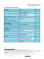
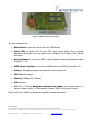
1.2 General Performance Data
Parameter
Connectivity
Supported traffic detectors
Supported outputs / interfaces
Number of detectors per TMIB
Number of virtual loops for
NEMA TS2
Number of loops replaced for
NEMA TS1 (4 detector slots used)
NEMA TS2 Detector BIUs
Environmental
Ambient Temperature
Humidity
Shock
Vibration
Mechanical
Weight TMIB_AB
Weight TMIB_C
Dimensions
Model No.
General
Power Supply
Form factor
Value
Unit
Smartmicro UMRR-0Axxxx
with RS485/CAN output
NEMA TS1 loop detector outputs
NEMA TS2 SDLC bus
100Base-TX Ethernet
Up to 4
Up to 16 per attached UMRR sensor
Up to 64 total
Up to 161
Up to 4 (Detector BIU 8 thru 11)
NEMA
NEMA
NEMA
NEMA
TS2
TS2
TS2
TS2
compliant2
compliant
compliant
compliant
360 / 12,7
130 / 4.59
See section 4
g / oz
TMIB_AB-00xxyy
TMIB_C-00xxyy
10 ... 30
<2.5 (operational) / <1.3 (idle)
3.7 for each connected sensor
NEMA TS1 / TS2 Inductive Loop
Detector Unit
V DC
W
W
1
TMIB_C Extension cards required for more than 4 loop detector outputs.
Batteries may have a reduced temperature range from -20°C to +70°C, the buzzer has a reduced temperature
range of -30°C to +70°C. These constraints do not limit normal operation of the TMIB.
2
PROPRIETARY
The information contained in this document may be subject to change without notice.
The information contained in this document shall remain the sole exclusive property of s.m.s smart microwave sensors GmbH.
TMIB Data Sheet.doc I Page 3 of 17 I September 18, 2015
www.smartmicro.de