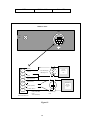
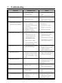
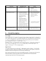
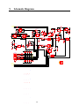
1
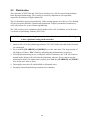
Service Manual
YSI Model 3100 Instrument
Conductivity
Salinity
Temperature
YSI INCORPORATED
1725 Brannum Lane
Yellow Springs, Ohio 45387 USA
Phone 937 767-7241 • 800 765-4974 • Fax 937 767-9353 • Inet [email protected]
Table of Contents
1. Introduction.................................................................................................................................................................................. 1
2. Principles of Operation.............................................................................................................................................................. 3
3. System Configuration and Operation...................................................................................................................................... 6
3.1 Configure the 3100 ..............................................................................................................................................................7
3.2 Cell Constant........................................................................................................................................................................7
3.3 Measurement Modes..........................................................................................................................................................8
3.4 Making Measurements.......................................................................................................................................................8
3.5 Autoranging & Range Searching .....................................................................................................................................9
4. Advanced Setup............................................................................................................................................................................ 9
4.1 Cell Calibration.....................................................................................................................................................................9
4.2 Setting the Temperature Coefficient...............................................................................................................................12
4.3 Reference Temperature.....................................................................................................................................................12
4.4 Manual Ranging................................................................................................................................................................12
5. Cell Maintenance ......................................................................................................................................................................13
5.1 Cleaning and Storage........................................................................................................................................................13
5.2 Platinization........................................................................................................................................................................14
6. Test and Verification Procedure............................................................................................................................................15
7. Troubleshooting ........................................................................................................................................................................17
8. Circuit Description...................................................................................................................................................................19
9. Schematic Diagrams ................................................................................................................................................................21
10. Board Layout............................................................................................................................................................................23
11. PC Board Parts List...............................................................................................................................................................24
12. Disassembly/Assembly Procedures ....................................................................................................................................25
12.2 PC Board Removal...........................................................................................................................................................25
13. Replacement Parts and Accessories ...................................................................................................................................26
14. Instrument Specifications .....................................................................................................................................................27
A31043A
i
031043
1.
Introduction
The YSI Model 3100 is a microprocessor based instrument designed to perform laboratory
measurement of conductivity, salinity and temperature. The instrument’s push button
operation makes it simple to use.
The Model 3100's microprocessor allows the system to be easily calibrated with the press
of a few keys. Additionally, the microprocessor performs a self-diagnostic routine each
time the instrument is turned on. The self-diagnostic routine provides you with useful
information about the cell constant, function of the instrument circuitry, and the quality of
the readings you obtain.
The system simultaneously displays temperature (in oC), along with one of the following
parameters: conductivity; temperature compensated conductivity; (in µS/cm or mS/cm), and
salinity (in parts per thousand [ppt]). You can switch back and forth from salinity,
conductivity, and temperature compensated conductivity with a single push of the [MODE]
key.
Capabilities
•
•
•
•
•
•
•
•
•
Adjustable reference temperature 15 to 25 °C
Automatic temperature compensation
Adjustable temperature compensation factor 0 to 4%/°C
Adjustable Cell constant, ranges:
0.01, 0.08-0.12, 0.8-1.2, 8-12
Auto or manual ranging
Conductivity or Salinity readings
7-pin mini DIN connector with thermistor connections
AC line power
Service Philosophy
The YSI Model 3100 is designed so that service can be performed easily by replacement of
components or entire sub-assemblies. A snap together case reduces disassembly time and
eliminates the need for elaborate tools.
Most service issues that occur in conductivity systems are caused by improper maintenance
of the cell. For this reason, troubleshooting efforts should be initially directed at
determining the condition and functionality of the cell and/or cable.
In the event that a problem is isolated to the instrument itself, YSI recommends
replacement of the entire defective sub-assembly rather than the individual components. To
lessen down time, YSI maintains an adequate stock of replacement sub-assemblies.
After servicing, the Verification Test should be performed to insure that the Model 3100 is
working properly. If components on the printed circuit board have been replaced as part of
the repair, and this test fails, the 3100 will need to be returned to YSI for factory software
calibration or the printed circuit board will have to be replaced.
1
2
2.
Principles of Operation
Conductivity Fundamentals
Electrical conductance (k) is defined as the ratio of the current (I) in a conductor to the
difference in the electrical potential (V) between its ends (k=I/V), measured in mhos or
siemens (S). Conductance, therefore, is not a specific measurement. Its value is dependent
upon the length of the conductor. Conductivity (ℵ
ℵ ), or specific conductance, is the
conductance per unit of conductor length. For our purposes, conductivity is defined as the
conductance in mhos or siemens measured across the sides of a one centimeter cube of
liquid at a specified temperature.
Looking at our electrodes as sides of a cube, it becomes apparent
that the conductance changes as the geometry of the cube
changes. If the cube lengthens with respect to the area of the
sides, then the conductance will decrease. If the area of the sides
increases with respect to the distance between them, then the
conductance will increase. The conductivity, however, will remain
the same, regardless of the geometry, provided that the
temperature and composition of the measured solution remain
constant. A factor called the cell constant (K) relates conductivity
to conductance. The cell constant is defined as the ratio of the distance between the
electrodes (d) to the area normal to the current flow (A):
Cell Constant =
ℵ
K=
= k ×K
Therefore, conductivity equals conductance
multiplied by the cell constant.
Example: For an observed conductance of 100 micro
mhos (100 microsiemens) and a cell
constant of 0.1/cm
ℵ = k × K
= 100 µ mho × 0.1 / cm
= 10 µ mho / cm
3
d
A
In SI units, the cell constant K=0.1/cm would become K=10/m, and the same conductivity
would be expressed:
ℵ = k × K
= 100 µ S × 10 / m
= 1 µ S/ m
Cell Constant
The cell constant (K) is used to determine the resistivity or conductivity of a solution. It is
defined as the ratio of the distance between electrodes (d) to the area normal to the current
flow (A). Cells with constants of 1.0/cm or greater normally have small, widely-spaced
electrodes, while cells with constants or 0.1/cm or less have larger electrodes that are
closely-spaced.
Cell Constant Calculation
Anytime the condition of the conductivity cell changes, it is possible that the cell constant
has also changed. Therefore, you should calibrate your system regularly. If you want to
manually calculate your cell constant, measure the conductance of a standard solution and
compare with the theoretical conductivity of the solution. The formula for determining the
cell constant is:
K =
where K
k
ℵ
ℵ
k
= cell constant in cgs metric units (cm-1)
= measured conductance in µ mho
= theoretical conductivity in µ mho/cm
The measured conductance (k) and conductivity (ℵ) must either be determined at the same
temperature or corrected to the same temperature for the equation to be valid. One main
reason for cell constant calibration is to increase overall system accuracy.
Conductivity Law
Solution
Conductivity
S/cm or mho/cm
mS/cm or mmho/cm
µS/cm or µmho/cm
Instrument
Conductance
S or mho
mS or mmho
µS or µmho
=
=
=
Cell Constant =
4
Solution Conductivity
Meter Conductance
×
×
×
Cell
Constant
1/cm
1/cm
1/cm
Meter Conductance =
5
Solution Conductivity
Cell Constant
Platinization
The electrodes of YSI 3200 and 3400 Series conductivity cells are coated with platinum
black during manufacturing. This coating is extremely important to cell operation,
especially in solutions of high conductivity.
The cell should be inspected periodically. If the coating appears to be thin or if it is flaking
off, the electrodes should be cleaned and replatinized. Properly maintained conductivity
cells will perform for years without replatinizing.
Salinity
Salinity is determined automatically from the Model 3100 conductivity and temperature
readings according to algorithms found in Standard Methods for the Examination of Water
and Wastewater (ed. 1995). The use of the "Practical Salinity Scale" results in values which
are unitless, since the measurements are carried out in reference to the conductivity of
standard sea water at 15°C. However, the unitless salinity values are very close to those
determined by the previously-used method where the mass of dissolved salts in a given
mass of water (parts per thousand) was reported. Hence, the designation "ppt" is reported by
the instrument to provide a more conventional output.
Temperature
The Model 3100 system utilizes a thermistor of sintered metallic oxide which changes
predictably in resistance with temperature variation. The algorithm for conversion of
resistance to temperature is built-in to the Model 3100 software, and accurate temperature
readings in degrees Celsius or Fahrenheit are provided automatically. No calibration or
maintenance of the temperature sensor is required.
3.
System Configuration and Operation
Plug the power supply (300 ma minimum @ 12 VDC) into its mating connector on the back
of the instrument. Depress the
(on/off) key to turn the instrument on. The instrument
will activate all segments of the display for a few seconds, which will be followed by a self
test procedure which will last for several more seconds. During this power on self test
sequence, the instrument’s microprocessor is verifying that the instrument is working
properly. The Model 3100 will display the current cell constant when the self test is
complete.
1.00
CEL
6
Cell constant
If the instrument were to detect a problem, the display would show a continuous error
message. For a list of these error messages, see the Troubleshooting chapter. After the
instrument completes this diagnostic routine, the following screen should be displayed
(with no cell connected).
0.00
µS
udr °C
3.1
Configure the 3100
Before operating the 3100, or whenever you change cells, you must configure the 3100 to
match the cell used. You must enter the manufacturer’s stated (or your manually calculated)
cell constant (K) as shown below (Cell Constant).
The default configuration is as follows:
•
•
3.2
Cell constant of K = 1
Temperature compensation corrected to 25°C using a coefficient of 1.91%/°C.
Cell Constant
Follow these steps to change the cell constant:
1. With the instrument on, press and release the [DOWN ARROW] and [MODE] keys at
the same time. The CAL symbol will appear at the bottom left of the display and the
large portion of the display will show 1.91% (or a value set previously using Setup).
2. Press and release the [MODE] key. The large portion of the display will show 25.0C (or
a value set previously using Setup).
3. Press and release the [MODE] key again. The large portion of the display will show
1.00 (or a value set previously using Setup).
4. Use the [UP ARROW] or [DOWN ARROW] key to change the value to the desired new
cell constant.
5. Press the [ENTER] key. The word “SAVE” will flash across the display for a second to
indicate that your change has been accepted. The 3100 will return to normal operation
mode.
7
3.3
Measurement Modes
The Model 3100 is designed to provide four distinct measurements:
Ø Conductivity -- A measurement of the conductive material in the liquid sample without
regard
to temperature
Ø Temperature Compensated Conductivity -- Automatically adjusts the reading to a
calculated
value which would have been read if the sample had been at 25o C (or
some
other reference temperature which you choose). See Advanced Setup.
NOTE: Requires YSI 3200 series cell.
Ø Salinity -- A calculation done by the instrument electronics, based upon the conductivity
and
temperature readings. NOTE: Requires YSI 3200 series cell.
Ø Temperature -- Always displayed.
To choose one of the measurement modes (temperature is always displayed), simply press
and release the [MODE] key. Carefully observe the small legends at the far right side of the
LCD.
Temperature
Compensated
Conductivity
with °C
Conductuctivity
with °C
Salinity
with °C
If the instrument is reading Temperature compensated conductivity, the large numbers on the
display will be followed by either a µS or mS and the small portion of the display will show
the oC flashing on and off.
If the instrument is reading Conductivity, the large numbers on the display will be followed
by either a µ S or mS, but the small portion of the display will show the oC NOT flashing.
If the instrument is reading Salinity, the large numbers on the display will be followed by a
ppt.
NOTE: Temperature compensated conductivity and salinity modes cannot be used unless a
YSI 3200 series cell is connected. When using a YSI 3400 series cell (or equivalent)
with the 3232 cell adapter, these modes will display an error message (“LErr”)
since 3400 series cells do not contain a temperature sensor.
3.4
Making Measurements
After setting up the 3100 instrument and cell as described earlier, the following basic steps
should be used to make measurements.
8
1. Verify that the 3100 is properly setup to use the current cell by measuring, or
calibrating with, a standard conductivity solution.
2. Immerse the cell in the solution to be measured.
3. Gently tap the cell to remove any air bubbles and dip the cell in the solution 2 or 3
times to ensure proper wetting. The cell electrodes must be submerged and the
electrode chamber must not contain any trapped air. If using a flow through or fill
cell, be certain it is completely full.
4. Allow time for the temperature to stabilize.
5. Press the [MODE] key to select the units required, then read the display.
6. Rinse the cell with distilled or deionized water.
3.5
Autoranging & Range Searching
The YSI Model 3100 is an autoranging instrument. This means that, regardless of the
conductivity or salinity of the solution (within the specifications of the instrument), all you
need to do to get the most accurate reading is to put the cell in the sample.
When you first place the cell into a sample or calibration solution, and again when you first
remove the cell, the instrument will go into a range search mode that may take as long as 5
seconds. During some range searches, the instrument display will flash rANG to indicate its
movement from one range to another.
The length of the range search depends on the number of ranges which must be searched in
order to find the correct range for the sample. During the range search, the instrument will
appear to freeze on a given reading for a few seconds then, once the range is located, will
pinpoint the exact reading on the display. The display may also switch to 00.0 for a second
or two during a range search before it selects the proper range.
During normal operation the [ENTER] key enables and disables the autoranging feature of
the instrument.
4.
Advanced Setup
For highest accuracy, the 3100 and cell may be calibrated as a system using standard
conductivity calibration solution and the temperature coefficient can be adjusted.
4.1
Cell Calibration
Prior to calibration of the YSI Model 3100, it is important to remember the following:
•
The cell constant must be set correctly before calibrating. See, Configure the 3100, Cell
Constant.
•
Always use clean, properly stored, NIST traceable calibration solutions. When filling a
calibration container prior to performing the calibration procedures, make certain that
9
the level of calibrant buffers is high enough in the container to cover the electrodes.
Gently agitate the cell to remove any bubbles in the conductivity cell.
•
Rinse the cell with distilled water (and wipe dry) between changes of calibration
solutions.
•
During calibration, allow the cell time to stabilize with regard to temperature
(approximately 60 seconds) before proceeding with the calibration process. The
readings after calibration are only as good as the calibration itself.
•
Perform calibration at a temperature as close to 25 °C as possible. This will minimize
any temperature compensation error.
Follow these steps to perform an accurate calibration of the YSI Model 3100 system (with
cell):
1. Select a calibration solution which is most similar to the sample you will be measuring.
•
For sea water choose a 50mS/cm conductivity standard (YSI 3165 or 3169)
•
For fresh water choose a 1mS/cm conductivity standard (YSI 3161 or 3167)
•
For brackish water choose a 10mS/cm conductivity standard (YSI 3163 or 3168)
2. Place at least 3 inches of solution in a clean glass beaker.
3. Insert the cell into the beaker deep enough to completely cover the electrodes. Do not
rest the cell on the bottom of the container -- suspend it above the bottom at least 1/4
inch.
4. Gently tap the cell to remove any air bubbles and dip the cell in the solution 2 or 3 times
to ensure proper wetting.
5. Allow at least 60 seconds for the temperature reading to become stable.
6. Press the [MODE] key until the instrument is in the mode that you want to calibrate in
as follows:
•
Temperature compensated conductivity (°C symbol flashing): This mode will
automatically compensate the calibration value to 25°C using a coefficient of
1.91%/°C.
•
Conductivity (°C symbol NOT flashing): This mode does NOT use temperature
compensation.
7. Press and release both the [UP ARROW] and [DOWN ARROW] keys at the same time.
The CAL symbol will appear at the bottom left of the display to indicate that the instrument
is now in Calibration mode.
8. Use the [UP ARROW] or [DOWN ARROW] key to adjust the reading on the display
until it matches the value of the calibration solution you are using. If you are calibrating
in temperature compensated conductivity mode, enter the value at 25°C. If you are
calibrating in conductivity mode (not temperature compensated), enter the value the
calibration solution should read at the current temperature.
10
9. Once the display reads the exact value of the calibration solution being used, press the
[ENTER] key. The word “SAVE” will flash across the display for a second indicating
that the calibration has been accepted.
The YSI Model 3100 is designed to retain its last calibration permanently. Therefore, there
is no need to calibrate the instrument after power down.
11
4.2
Setting the Temperature Coefficient
Follow these steps to modify the temperature coefficient of the Model 3100.
1. Press and release the [DOWN ARROW] and [MODE] keys at the same time. The CAL
symbol will appear at the bottom left of the display and the large portion of the display
%
will show 1.91 (or a value set previously using Advanced Setup).
2. Use the [UP ARROW] or [DOWN ARROW] key to change the value to the desired new
temperature coefficient.
3. Press the [ENTER] key. The word “SAVE” will flash across the display for a second to
indicate that your change has been accepted.
4. Press the [MODE] key two times to return to normal operation; the CAL symbol will
disappear from the display.
4.3
Reference Temperature
Follow these steps to modify the reference temperature of the Model 3100.
1. Press and release the [DOWN ARROW] and [MODE] keys at the same time.
The CAL symbol will appear at the bottom left of the display and the large portion of the
%
display will show 1.91 (or a value set previously using Advanced Setup).
2. Press and release the [MODE] key. The large portion of the display will show 25.0C
(or a value set previously using Advanced Setup).
3. Use the [UP ARROW] or [DOWN ARROW] key to change the value to the desired new
reference temperature (the allowable range is 15°C to 25°C).
4. Press the [ENTER] key. The word “SAVE” will flash on the display for a second to
indicate that your change has been accepted.
5. Press the [MODE] key to return to normal operation.
4.4
Manual Ranging
If your application is easier to perform using a manual range that you select, the YSI Model
3100 allows you to turn off the default autoranging feature. While you are making
conductivity or temperature compensated conductivity measurements, simply press and
release the [ENTER] key. Each additional press of the [ENTER] key will cycle the Model
3100 to a different manual range until you return again to autoranging. Five pushes of the
[ENTER] key will cycle the Model 3100 through the four available manual ranges and
return the instrument to autoranging.
NOTE: You may see an error message in some manual ranges if the range selected is not
adequate for the sample you are measuring.
If this happens, simply press and release the [ENTER] key again until a range is selected
which is suitable for your sample. If you get lost and don’t know if you’re in a manual range
12
or autoranging, simply turn the instrument off and back on. The instrument will default to
autoranging when first turned on.
The YSI Model 3100 has five possible ranges. The number of ranges available for use
depends on the current cell constant.
Cell
Constant
Range 1
Range 2
Range 3
Range 4
Range 5
0 - 49.99 µS/cm
0 - 499.9 µS/cm
0 - 4999 µS/cm
0 - 49.99 mS/cm
0 - 499.9 mS/cm
K=0.01
√
√
K=0.1
√
√
√
K=1
√
√
√
√
√
√
√
K=10
√
NOTE: Cells may be used beyond their normal range, but with instability and/or reduced
accuracy.
5.
Cell Maintenance
5.1
Cleaning and Storage
The single most important requirement for accurate and reproducible results in conductivity
measurement is a clean cell. A dirty cell will change the conductivity of a solution by
contaminating it.
Cleaning the Cell
1. Dip or fill the cell with cleaning solution and agitate for two to three minutes. Any
one of the foaming acid tile cleaners, such as Dow Chemical Bathroom Cleaner, will
clean the cell adequately. When a stronger cleaning preparation is required, use a
solution of 1:1 isopropyl alcohol and 10N HCl or Sulfuric Acid or Ethanol or
Methanol.
CAUTION: Cells should not be cleaned in aqua regia or in any solution known to
etch
platinum or gold.
2. Remove the cell from the solution and rinse in several changes of distilled or
deionized water. Inspect the platinum black to see if replatinizing is required.
Storage
Short term: Store conductivity cells in deionized or distilled water. Change the water
frequently to prevent any growth that may cause electrode fouling.
Long term: Rinse thoroughly with deionized or distilled water and store dry. Any cell that
has been stored dry should be soaked in distilled water until the electrodes
appear black before use.
13
5.2
Platinization
The electrodes of YSI 3200 and 3400 Series conductivity cells are coated with platinum
black during manufacturing. This coating is extremely important to cell operation,
especially in solutions of high conductivity.
The cell should be inspected periodically. If the coating appears to be thin or if it is flaking
off, the electrodes should be cleaned and replatinized. Properly maintained conductivity
cells will perform for years without replatinizing.
The 3100 can be used to replatinize the electrodes of the cell. In addition, you will need a
2-oz bottle of platinizing solution (YSI 3140).
WARNING: Before replatinizing the electrodes of a cell, make sure that the cell is designed
to have a platinum coating on the electrodes.
1. Immerse the cell in the platinizing solution (YSI 3140). Make sure that both electrodes
are submerged.
2. Press both the [UP ARROW] and [MODE] keys at the same time. The large portion of
the display will show “PLA” flashing, indicating that platinization is in process.
3. After the platinization process is complete (about 30 minutes), the 3100 will return to
normal mode. Remove the cell from the platinizing solution. If you want to stop the
platinization before 30 minutes have passed, press both the [UP ARROW] and [MODE]
keys at the same time to abort.
4. Thoroughly rinse the cell with distilled or deionized water.
5. Promptly return the platinizing solution to its container.
14
6.
Test and Verification Procedure
Connect the YSI Model 3100 as shown in Figure #1 (next page) and follow the charts below
to verify it’s electronic accuracy. Test the system accuracy (instrument and cell) using
conductivty standards. See Cell Calibration.
Equipment Required:
If using the YSI 3166 Precision Calibrator Set to simulate conductance a YSI 3232 adapter
is required for proper connection to the cell connector. Temperature can only be accessed
using the YSI #003229 cable assembly. See figure #1.
If a decade resistance box is used to simulate conductance and temperature a YSI #003229
cable is required for connection to the cell connector.
Important Notes:
1. Place the Model 3100 in conductivity mode with temperature compensation turned off
(°C not flashing).
2. Model 3100 cell constant set to 1.00. See Configure, Cell Constant.
3. The 3100 has no internal calibration. Opening the case should only be attempted by a
qualified service technician or permanent damage may result.
Conductance Verification
Resistance Input @ Cell
Connector
3100 Range
Displayed
Conductance
10.00 Ω ± 0.2%
499.9 mS
100.0 ± 2.6 mS
100.00 Ω ± 0.1%
49.99 mS
10.00 ± .26 mS
1000.0 Ω ± 0.1%
4999 µS
1000 ± 26 µS
10.0 KΩ ± 0.1%
499.9 µS
100.0 ± 2.6 µS
100.0 KΩ ± 0.1%
49.99 µS
10.00 ± .26 µS
1.000 MΩ ± 0.1%
49.99 µS
1.00 ± .25 µS
Temperature Verification
Temperature
Resistance Input @ Cell
Connector, Pin 1 & 2
Displayed Temperature
0 oC
32660 Ω ± .25%
0.0 ± .2 oC
25 oC
10000 Ω ± .25%
25.0 ± .2 oC
40 oC
5329 Ω ± .25%
40.0 ± .2 oC
15
1752 Ω ± .25%
70 oC
70.0 ± .2 oC
3100 Rear Panel
CELL
12.0
VDC
1
2
3
4
5
Black
1
Cell Thermistor
10K Ω@ 25 o C
Green
2
T
6
7
Decade
Resistance
Box
Red
3
Brown (Drive)
4
Blue (Sense)
YSI 3166 or
Decade
Resistance
Box
5
White (Sense)
6
Yellow (Drive)
7
3100’s 7-Pin Mini
DIN Cell Connector
Cable, Mini DIN
Conn.
YSI # (003229)
Conductivity
Cell
Figure #1
16
7.
Troubleshooting
SYMPTOM
1.
2.
3.
Instrument will not turn on
Instrument fails verification test
System readings are inaccurate
(Instrument and cell combination)
4.
5.
6.
Main Display reads “OVEr”
Main Display reads “Undr”
Main Display reads “rErr”
POSSIBLE CAUSE
•
•
Power supply failure
Instrument failure
ACTION
•
•
Check power supply and AC
outlet
Repair or replace board assy
•
Incorrect calibration procedure
•
See Cell Calibration
•
Board requires service
•
Repair or replace board assy
•
Board needs factory calibration
•
Calibration is required
•
See Cell Calibration
•
Cell is contaminated
•
See Maintenance
•
Temperature coefficient has been
set incorrectly
•
See Temperature Coefficient
•
Reference temperature incorrect
•
See Reference Temperature
•
Readings are or are not
temperature compensated.
•
See Measurement Modes
•
Conductivity Reading is over
range:
>112 uS with K=0.01 cell
>11.2 mS with K=0.1 cell
>112 mS with K=1 cell
>499.9 mS with K=10 cell
•
In all cases, check calibration
values and procedure; check
Advanced Setup settings.
•
Set cell constant to correct range.
•
If each of these is set correctly,
repair or replace board assy.
•
Set cell constant to correct range.
•
Recalibrate using known good
conductivity standard.
•
Follow cell cleaning procedure.
•
Use the ENTER key to select a
higher or lower manual range, or to
set system to Autoranging.
•
Salinity reading is > 80ppt
•
User cell constant cal is over the
limit of the current range
•
User cell constant cal is under the
limit of the current range
•
User has selected manual ranging
& sample exceeds selected range
•
Conductivity reading is over the
range of the instrument: >499.9
mS
7.
Main Display reads “PErr”
•
Incorrect sequence of key strokes
•
Refer to manual section which
provides step by step procedures
for the function you are
attempting.
8.
Secondary Display reads “Err ra”
•
System has failed its RAM test
check procedure
•
Turn instrument OFF and back
ON.
•
Repair or replace board assy
•
Turn instrument OFF and back
ON.
•
Repair or replace board assy.
9.
Secondary Display reads “Err ro”
10. Secondary Display reads “udr”
•
System has failed its ROM test
check procedure
•
Current cell does not contain a
temperature sensor (such as YSI
3400 series).
•
Use a YSI 3200 series cell if
temperature readings or
compensation are required
•
Temperature is < -5o C
•
Read solution of higher
17
SYMPTOM
POSSIBLE CAUSE
ACTION
temperature
18
•
Replace Cell/Cable assy
•
Repair or replace board assy
SYMPTOM
11. Secondary Display reads “ovr”
12. Main Display reads “LErr”
13. Secondary Display reads “rEr”
8.
POSSIBLE CAUSE
•
o
Temperature is > 95 C
•
In temperature compensated
conductivity mode, temperature
exceeds the values computed using
user defined temperature
coefficient and/or reference
temperature.
•
In cell constant cal mode,
temperature exceeds the values
computed using user defined
temperature coefficient and/or
reference temperature.
•
The user has selected Temperature
Compensated Conductivity or
Salinity and the current cell does
not contain a temperature sensor.
•
Temperature jumper is set to o F
and reading is >199.9 o F but < 203
o
F
ACTION
•
Read solution of lower
temperature
•
Replace Cell/Cable assy.
•
Repair or replace board assy
•
Adjust user defined temperature
coefficient (see Temperature
Coefficient) or reference
temperature (see Reference
Temperature)
•
Use a YSI 3200 series cell or turn
off temperature compensation.
•
Set jumper to read o C.
•
Repair or replace board assy
Circuit Description
Power Supply
Power is input at JP2 (12V nominal). U8 regulates this input voltage to approximately 5v and supplies it
to U9, which is always powered, even when the instrument is off. R26 pulls the power switch line up to
5v, U9 pin 13 is pulled back low when the power button is depressed. The micro (U15) holds the
power on through U9 (U9 pin 8 > 4v and U9 pin 11 < 1v).
Regulator U10 has a 6 volt output which is set by divider R28 & R29. U10 shuts down when pin 5 is
low. C18 & 19 are output caps. U11 is a -5 to -6v charge pump, it should output negative 5 to
negative 6 volts on pin 5. C22 is its output capacitor.
Digital Section
U15, system microprocessor, runs when pin 17 is high and the crystal is oscillating. U14 will pull the
reset line low under low input power conditions. R33, R34 and R43 are not required, so may not be
installed on all boards. Serial port JP4 is used for factory calibration only.
Data is output to the display driver chip in four bit nibbles on port B. U16 drives the LCD. The LCD
holder and conductive strips (zebra strips) must be mounted flush to the PCB board and the
connections kept clean for the LCD to properly operate.
19
Analog Section
The Model 3100 uses the “Forced Current” measurement technique. This technique uses a voltagemode feedback loop around a square-wave current source so that the output of the current source
generates a fixed AC voltage across the conductivity cell. Since the current required to produce a fixed
voltage across the cell is proportional to the conductance of the cell, the DC programming voltage to the
square-wave current source is proportional to the conductance of the cell.
U1 is a switched-capacitor device that converts the DC programming voltage to a symmetrical squarewave which provides the floating reference voltage for current source U2a. U1 gets its clock from the
system controller via level-shifter Q1. Current source U2a uses reference resistors R5 - R8 as selected
by analog switch U3, which provides four decade ranges of cell current. The cell drive current is
supplied by U2a, and returned through inverting current-sink U2b, which provides a cell drive that is
symmetrical with respect to circuit common. The potential across the cell is buffered by U2c and U2d,
and sampled by U4 acting as a synchronous demodulator to convert the cell potential into a DC voltage.
The demodulator uses a center-sampling technique to minimize both series and parallel capacitance
errors. The demodulator output is compared to a reference voltage of 120mV by integrating
comparitor U5, which provides the reference voltage for the square-wave current source, and the input
voltage for the conductivity channel of the A/D converter MUX U6c.
Conductivity cell platinization is provided by U6a and U6b, which open the main feedback loop, and
use the system reference voltage as the programming voltage for the current source. The current source
is clocked at 0.05Hz to provide platinizing current which switches polarity every 10 seconds.
Temperature is measured by a thermistor connected to the input of buffer-amp U7. Current through the
thermistor is supplied from the system reference through precision resistor R23. The output of U7c is
connected to the temperature channel of A/D MUX U6c.
Analog-to-digital conversion is done by dual-slope integrator U13. U13 (TSC500A) is the analog half
of an A/D, which provides all of the signal switching and buffering functions, but leaves the timing and
control to the system controller.
20
9.
Schematic Diagrams
1 R452
1 33k 2
RANGESEL1
RANGESEL2
HC4053
SEL
R6
9.09k
8
11
U1
10
LTC1043
C- 12
AGND
13 S3
S4 14
6 S1
5
2
U1
1
LTC1043
C- 3
18 S3
S4 15
C2
S2
C+
SH
1
2
.1uF
C1
S2
C+
SH
1 R472
22k
1
1
R7
909.0
2
.1uF
.1uF
1
C31
1
2
7 S1
2
2
4
22
51
10
3
2
AGND
V-
U3 COM 3
2
R5-R10 : 25PPM
1
1 R122
1M
AGND
C36
1
1 R162
10k
1
R14
10M
MOD_CLK
OP177
+
2
U76
AGND
4
8
V+
1
AGND
2
0.47
2
V-
V+
7
4
2
5
0 1
3
2
1
1 R182
10k
2
3
ADC+
1
OP177
+
4
U5
6
13 1
1N4148
1 2
D11
12 0
1
SEL
R22
10K
2
V-
47p
2
2
Q1
1
16
R3
33K
2
OSC
U1
1
R2
100K
V+
2n5087
3
V+
1
6 7 1 R112
5 U2
+ LMC6484 100
2
.1uF
17 V-LTC1043
NC9
2
1 R9 2
100k
C3
4
AGND
1 R132
1M
1 R172
10k
1
R15
10M
AGND
LMC6484 C11
12 +
13 COM U4
U2 14
0.47_MYLAR HC4052
13 1
2
AGND
C4
.1uF
V-
1
2
2
L8
D
2
2
1
2
D
11
2
D
11
2
D
RT1
2 L9
11
11
7Pin mDIN
D9
2
(to C17 gnd side)
AGND
L11 1
2
15uH
L13 1
2 L10 1
15uH
2
16
VDD
9
10 B
U4
6A
INH HC4052
7
VSSVEE
8
1
R48
562k
AGND
2
R21
60.4k
2
VR
AGND
1
R49
10k
V2
AGND
RT2
100uH
2
1
2
1
1
15uH
1
DRIVE2
15
COM
10
SEL
U6
1
1
0
2
HC4053
SENSE2
L12 1
SENSE1
15uH
DRIVE1
2
1
D
2
11
D
2
D
11
2
AGND
11
11
D
2
15uH
8
D10 AGND
1
11 3
15 2
14 1
12 0
4
3
7
7
4
1
8
4
4
1
7
4
4
1
6
4
4
1
5
4
N
N
2
N
N
N
1
N
N
N
N
N
V-
1
1
1
21
1
DEMODCLK1
DEMODCLK2
PLAT
C/TSEL
R19
1k
V+
C12
1
AGND
V+
9
11
15
14
12
0.1
AGND
JP1 1
2
3
4
5
6
7
3
2
1
0
2
1
AGND
AGND
2
U3 COM 13
HC4052
U6 COM 14
HC4053
1
8
AGND
C5
1
2
0.1
C13
1
R1
100K
C16
1
1N4148
1 2
2
1 R102
100k
U6
VDD
16
V+
VD12
4
VCC
U2
LMC6484
VEE
11
.1uF
AGND
LMC6484 C8
10 +U2
3 COM U4
8
0.47_MYLAR HC4052
9 1
3
AGND
2
.1uF
AGND
R8
100
2
C35
16
VDD 9
B
U3
A 10
6
7 HC4052
VEEVSSINH
8
HC4052
1
AGND
V+
2
1
C14
V+
2
C15
2
C34
1
V-
8
VSSVEE
INH HC4053
7
2
R5
90.9k
0.22
2
AGND
VR
LMC6484
3 +U2
1
222pf
6
0.1
1
1
1
U6 COM 4
C17
1
R4
10M
1 R242
1k
0.1
0
3
1
1 R232
4.22k
1
5
7
PLAT
9
1 R252
1.50k
V+
RT2
R46
33k
11
L
W
V+
N
V+
C28
1
2
R44
100k
26
2
P
CD4011B
6
1
/
OC3/PA5 29
30
OC4/PA4
OC5/PA3 31
MOD_CLK
10
1
2
3
4
5
6
7
8
9
10
11
12
13
14
15
16
17
18
19
20
21
22
23
24
RDY
DEMODCLK2
WE
PLAT
D3
D2
D1
D0
U15
12
13
CD4011B
11
U9
CD4011B
2
O
R27
220k
3
U9
9
1
DGND
B
A
POWER
S64
S63
DGND S62
S61
S60
S59
S58
S57
S56
S55
S54
S53
1
D
M
E
4
H
U
A
P
T
HD61603
2
2
2
2
2
3
3
3
3
3
3
3
T
3
3
3
4
5
5
5
4
4
4
4
4
4
4
4
4
4
3
3
3
S
S
S
S
S
S
S
S
S
S
S
S
S
S
S
S
C19
0.47
VR
1
+
2
U
8
3
2
C20
22
LCD1
LCD_PN_0701032
V-
W
F
F
AGND
F
DGND
3
1
1 G
2
1
1
2
1
1
F 2
2
2
2
2
2 G
3
6
3
C
D
C
D
9
2
22
B
A
E
B
E
A
B
D
C
E
A
B
A
A
D
C
E
E
E
B
B
A
A
6
E
D
C
N
0
1
2
3
4
5
6
7
8
9
0
1
2
3
4
5
6
7
8
9
0
1
2
3
4
5
6
M
1
C
D
Important: U15, Microcontroller, is not field replaceable because it programed for a
specific board during factory calibration.
C
C
D
G
G
G
0
E
42
O41
40
49
58
7
6
5
4
3
2
1
0
19
28
37
46
5
4
03
52
21
60
79
18
87
96
05
34
63
72
81
90
09
48
17
F
1
1
F 1
1
6
6
6 G
2
2
O
DGND
G
C22
100
F
A
1
+
2
1 NC
V+ 8
2 CAP+U11 OSC7
3
6
ICL
LV
4 GND
CAP- 7660 VOUT5
1
2 C
S
DN3
4ATS
5 C
B
6 5
7 6
8 6
9
1 6
6
1 6
1
1 6
6
1 7
1
1 7
7
1 7
1
5
1 7
76
2
7
2 78
2 P
89
2 80
2 81
2 82
2
3
2 8
84
2
5
2 86
3 F
C7
3 P8
3
9
M0
3 M
3 V
3
M
3 %
C21
10
S
S
S
S
S
S
S
S
S
S
S
S
S
S
S
S
S
S
S
S
S
S
S
S
S
S
S
S
S
S
S
S
S
S
S
S
2
1
+
2
O
R
DGND
2
C18
100
R29
9.09K,1%
B
R30
15k
2
1
1
6 7
A
16 7
7
16
6 6
15 6
1
6
L6
5
1 6
6
15
5 6
16 6
P
6
25
5 6
25 6
2
5
25
5 5
24 5
2
5
P4
5 5
S 4 5
3
4 5
34
5
34 5
3
5
34
34 4
4
34
4 4
P3 4
4
3 4
43
4
A 6 4
4
D 4
43
3 4
4
43 4
3
43
3 3
46 3
P
1
R28
5.49K,1%
2
S
RS 1
L
S
S
S
S
S
S
S
S
S
S
S
S
S
S
S
S
5
2
2
S
1 1
2 5 1
S
5 0
0
S
4
9
S
4 9
8
8
S
4 7
7
S
4 6
6
S
4 5
5
S
4
4
S
4 4
3
3
S
4
2
S
4 2
1
L 4 1
S
0
0
S
3 9
9
S
3
8
8
S
3 7
7
S
S
S
V+
1
2
1
IN
OUT
NC1 NC3 7
SHDNNC2 6
2
GND ADJ
LT1121
1
+
2
J
3
DGND
SHUTDN
U10
2
8
4
5
3
U16
S13
S14
S15
S16
S17
S18
S19
S20
S21
S22
S23
S24
S25
S26
S27
S28
S29
S30
S31
S32
S33
S34
S35
S36
2
DGND
B
1
VDD
RDY
CS
WE
RE
SB
D3
D2
D1
D0
VSS
VS
C0
S63
S62
S61
S60
S59
S58
S57
S56
S55
S54
S53
R26
1K_1%
B_REG
4
S5
3
4
2
1
0
2 9
3
8
7
6
4
4
3
2
1
0
9
8
5
7
6
5
4
P3
2
1
0
9
8
6
4
5
4
7
3
2
4
U8
81250
3
I
O
G
1
2
1
B
4 1
S4
3 2
2
V+
DEMODCLK1
8
COMPLY
4 1
S3
3 2
8
9
DGND
R37
357K
RN1
100k
3
RANGESEL2
3
DGND
4 1
S2
3 2
DGND
1
DGND
CD4011B
4 1
S1
3 2
V+
C/TSEL
RANGESEL1
1
2
2
RDY
WE
D3
D2
D1
D0
PA7/OC1 27
PA6/OC2 28
VSS
DGND
4
32
38
39
40
41
42
37
1
2
DGND
G
3
R36 V+
15k
2
1 0
1
1 2
1
1
U9
VRL
MC68HC711E9CFN2
O 0
1
2
DGND
1 JP4
2
3
4
RXD
TXD
S
C
SCI
O
2
o
COMPLY
1
PA2/IC1
PB4
PB3
PB2
PB1
PB0
PB5
1
RN1
100k
2
S
S
S
S
S
S
S
S
S
S
S
S
S
C27
2
J1
o
F
ENTER
MODE
DOWN
UP
VRH
PE1/AN1
PE2/AN2
PE3/AN3
PE4/AN4
PE5/AN5
PE6/AN6
PE7/AN7
PC6
PC7
PD2
PD3
PD4
PD5
PA1/IC2
1
1
1
RN1
RN1 RN1
100k 100k 100k
6
7
8
8
7
7
7
S 7
S
S 7
S 7
S 7
7
S 7
S
S 7
6
S 6
S
6
S 1
1 6
S 1 6
S
1
C26
.1uF
.1uF
1
2
3
4
45
47
49
44
46
48
50
15
16
22
23
24
25
33
RN1
100k
O
O
S
51
DGND
AGND
5
RXD/PD0 20
TXD/PD1 21
0.1
2
DGND
2
AN0/PE0
DGND
AGND
U9
43
10
11
12
13
14
9
5
Y
*
1
DGND
N
0.1
PC1
PC2
PC3
PC4
PC5
PC0
1
3
DGND
C
2
E
STRB
STRA
IC3/PA0
PB7
PB6
52
2
20pf
S
S
301k
V+
1
V+
2
Q2
2N5087
C
1
*
1 R342
280k*
R43
392k
V1
TSC500
R33*
2
2
POWER
2
20pF
X1
4MHz C30
E
CREFCOUT
1
1 R32 2
100k
B
2
R35
10M
7
2
3
4
5
6
0
1
6
14
1
2
0.1
1 R312
120k C24
C23
0.1
.33uF
V+
C
CREF+
DGND
5
6
4
34
35
36
1
7
2
11
10
13
12
4
3
1
16
15
2
2
C25
1
VIN+
VINB
A
BUF
CAZ
CIN
VS+
GND
VS-
C
2
REFH
REFL
ACOM
1
9
8
5
8
XTAL
C29
1
1
XIRQ 18
U13
VR
EXTAL 7
L
ADC+
VDD
P
S8054
2
1
I
O
G
3
IRQ
MODB
MODA
RESET
1
19
2
3
17
U14
1
3
DGND
0
C
9S
SC
8
7S
6S
S
5S
4S
3S
2
1S
S
0
9S
8S
S
7S P
6
5S
S
S
.1uF
1
RN1
100k
4
O
1
1
RN1
100k
9
64
63
62
61
60
59
58
57
56
55
54
53
52
51
50
49
48
47
46
45
44
43
42
41
S13
S14
S15
S16
S17
S18
S19
S20
S21
S22
S23
S24
S25
S26
S27
S28
S29
S30
S31
S32
S33
S34
S35
S36
10. Board Layout
D6
D5
D7
D8
D10
C17
R23
R24
L11
L8
L9
L12
L13
L10
U7
R12
C22
D2
D1
C35
D3
D4
D9
R25
C31
R13
C18
C19
U16
R26
U8
R15
R17
R14
R16
C36
R11
R10
R9
R8
R47
C5
U2
C3
C34
U10
LCD1
R28
C4
R29
C1
R37
C21
C8
U1
Q1
U11
R3
R2
R1
R5
R6
R7
C2
U9
R45
U3
C12
C16
R36
R46
C11
C14
S2
S5
1
JP4
C15
5V
R4
C13
Tx
RN1
GROUND
CLIP
Rx
C28
R49
R19
R18
U4
G
R27
R32
S4
GROUND
CLIP
U6
D11
S1
U14
S3
C26
C23
C27
C30
Q2
R21
R48
D12
C24
C32
U15
X1
R35
R31
U12
F
o
C
o
C20
C33
R30
U13
C25
1
R43
R34
R33
23
J1
C29
R44
R22
U5
11. PC Board Parts List
Reference Designator(s)
Description
R1, R2, R9, R10, R32, R44
R3, R45, R46
R12, R13
R5
R6, R29
R7
R8
R48
R11
R4, R14, R15, R35
R19, R24, R26
R21
R16~18, R22, R49, R50
R23
R25
R27
R28
R30, R36
R31
R37
R51
RN1
C1, C2, C17, C24, C25
C3, C4, C12, C15, C16, C26∼28, C32∼36
C5
C29∼31
C14
C8, C11, C13
C18, C22
C19
C20
C21
C23
D1∼8, D11
D9, D10
U1
U2
U3, U4
U5, U7
U6
U8
U9
U10
U11
U12
U13
U14
U16
Q1, Q2
X1
JP1
JP2
JP4, JP1
S1∼S5
L8, L10∼L13
L9
Res, 100K, 1%, 1/4W
Res, 33K, 5%, 1/4W
Res, 1.0M, 5%, 1/4W
Res, 90.9K, 1%, 1/4W
Res, 9.09K, 1%, 1/4W
Res, 909K, 1%, 1/4W
Res, 100, 1%, 1/4W
Res, 562K, 1%, 1/4W
Res, 100, 5%, 1/4W
Res, 10.0M, 5%, 1/4W
Res, 1.0K, 1%, 1/4W
Res, 60.4K, 1%, 1/4W
Res, 10K, 5%, 1/4W
Res, 4.22K, 1%, 1/4W
Res, 1.50K, 1%, 1/4W
Res, 220K, 5%, 1/4W
Res, 5.49K, 1%, 1/4W
Res, 15.0K, 5%, 1/4W
Res, 120K, 1%, 1/4W
Res, 357K, 5%, 1/4W
Res, 22.1K, 5%, 1/4W
Res Network, 100K, SIP
Capr, MPE, 0.1µF, 63V
Capr, Multi, 0.1µF, 50V
Capr, Cer, 47pF
Capr, Ce, 22pF
Capr, MPE, 0.22µF, 63V
Capr, MPE, 0.47µF
Capr, Ele, 100µF, 16V
Capr, Multi, 0.47µF, 50V
Capr, Ele, 22µF, 16V
Capr, Ele, 10µF, 16V
Capr, MPE, 0.33µF, 63V
Diode, 1N4148
Diode, Zener, 7.5V
IC, LTC1043CN
IC, LMC6468, OP Amp
IC, 74HC4052BCN, Multiplexer
IC, OP177GP, OP Amp
IC, CD4053BCN, Multiplexer
Regulator, S8125OHG
IC, CD4011BCN, NAND
IC, LT1121CN8, Regulator
IC, TC7660CPA, DC-DC Con.
Low Volt Ref, ICL8069DCZR
IC, TC500CPE, Analog Process
Detector, S8054ALR
IC, HD61603, LCD Driver
Transistor, 2N5087, PNP
Crystal, 4.0 MHZ
Conn, Mini-DIN, 7-Pin
Battery Conn, Switch
Conn., 4 pin wafer
Switch, SMT, Single Pole
Inductor, 15µH ±10%
Inductor, 100µH ±10%
Bracket, LCD
24
YSI Part #
3161001
031204
041032
031249
031205
031206
031207
031208
031248
031210
031247
031212
040838
092806
031246
031213
040813
031215
031216
031220
031221
031145
031223
031224
031225
031226
031227
031228
031229
031230
069864
031231
031232
031201
031202
060873
031234
031250
031236
031237
031238
078595
031239
031240
031241
031242
031243
031245
031203
031146
031149
031148
031144
031251
031253
031254
031154
12. Disassembly/Assembly Procedures
NOTE: The following procedure should
only be performed by a qualified service
technician.
C
Case Disassembly
•
•
•
•
•
While applying slight separation force
to the front, curved edge of the case
near one corner, use a small straightblade screwdriver to release the snap
(A) on the same side.
When that snap releases, keep
applying the separation force, and use
the screwdriver to release the front
snap (B) nearest the same corner.
Repeat the procedure on the other
corner to release both front and both
side snaps.
Swing the case open slowly, pivoting
on the three rear snaps (C) until they
release.
Lay the lower case assembly to the side.
A
B
12.2 PC Board Removal
•
•
Gently release the two snaps nearest the front, curved edge of the unit.
With the snaps released, lift the front of the board slightly and slide the board out of the
rear connector openings.
PC Board Re-installation
•
•
•
Remove the protective covering from the display. DO NOT TOUCH THE FACE OF
THE DISPLAY, FINGERPRINTS AND DUST CANNOT BE EASILY REMOVED.
Slip the connector end of the board into place against the gaskets at the rear of the case,
then rotate the board down into position, engaging each snap as you go. Be sure that the
switch extenders line up with the switches.
Inspect the assembly to insure that all board snaps are fully engaged and the board is in
the proper position in the case. Turn the assembly over and activate each switch. Be sure
you can hear and feel each switch click as it is pressed.
Case Re-assembly
•
Hook the three snaps at the rear of the case into place and rotate the lower case into
place on the upper case. Make sure all four snaps are fully engaged. Press firmly down
on the three rear snaps to make sure they are completely engaged.
25
13.
Replacement Parts and Accessories
YSI Item #
Description
Comments
003208
3208 Power Supply, 115 VAC
003209
3209 Power Supply, 240 VAC
031008
Overlay, Window
031009
Overlay, Keypad
051009
Window
113117
Board Assy, PC, Main
113138
Case Assy, Upper
111027
Case Assy, Lower
003226
Weight, SS
051043
Foot, Rubber, Self-Stick
032061
Gasket, Connector, Cell
032063
Gasket, Connector, Power
051025
Standoff, .25, Snap-In
Retain display
031155
Display, Liquid Crystal
LCD1
003228
Extension, Switch
031041
Operations Manual
031043
Service Manual
003229
Cable Assy, Cell
7-pin mini DIN to pigtail
3232
Cell adapter
For YSI 3400 Series cells
3166
Calibrator resistor set
Requires 3232 cell adapter
Includes 003226 weight
26
14. Instrument Specifications
Modes:
Conductivity
Temperature compensated conductivity
Salinity
Temperature
Conductivity:
Range
0 - 49.99 µS*
0 - 499.9 µS
0 - 4999 µS**
0 - 49.99 mS***
0 - 499.9 mS****
Accuracy
± 0.5% full scale
± 0.5% full scale
± 0.5% full scale
± 0.5% full scale
± 0.5% full scale
Resolution
0.01 µS
0.1 µS
1 µS
0.01 mS
0.1 mS
Salinity:
Range
0-80 ppt (NaCl)
Accuracy
±2% or ±0.1 ppt
Resolution
0.1 ppt
Temperature:
Range
-5 - 95°C
Accuracy
±0.1°C +1LSD
Resolution
0.1°C
Temperature Compensation:
Method:
Ref. temp., °C:
Temp. Coefficient:
Frequency
70 Hz
70 Hz
240 Hz
1562 Hz
1562 Hz
Linear
15 - 25
0 - 4%/°C
Cell constant, cm-1 :
0.01
0.08 - 0.12
0.8 - 1.2
8 - 12
Power Adaptor:
AC, 115V, 220V
Instrument Power:
12 VDC, 300mA max
Approvals:
UL, CSA, CE
Environmental requirements:
95% RH non-cond
Size:
9 x 9.5 x 4.4 inches
22.9 x 24.1 x 11.2 cm
Weight:
2.6 pounds
1.1 kg
* Requires a cell constant of K=0.01, K=0.1 or K=1.
** Requires a cell constant of K=0.1, K=1 or K=10.
*** Requires a cell constant of K=1 or K=10.
**** Requires a cell constant of K=10.
27