1
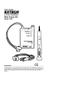
® USSD4250 MICROSTEP DRIVER USER’S MANUAL USSD4250 User's Manual Revision 1.1 © 2010 USAutomation, Inc. All rights reserved USAutomation® USSD4250 User's Manual This manual, as well as the software described in it, is furnished under license and may be used or copied only in accordance with the terms of such license. The content of this manual is furnished for informational use only, is subject to change without notice and should not be construed as a commitment by USAutomation. USAutomation assumes no responsibility or liability for any errors or inaccuracies that may appear herein. Except as permitted by such license, no part of this publication may be reproduced, stored in a retrieval system or transmitted, in any form or by any means, electronic, mechanical, recording, or otherwise, without the prior written permission of USAutomation. USAutomation, Inc. 23011 Moulton Parkway Suite J2 Laguna Hills, CA 92653 (949) 588-0513 (949) 588-8761 fax www.usautomation.com USSD4250 User's Manual Revision 1.1 2 Revision Notes 1.0 Original release 1.1 4/22/11 - Added DIP switch setting drawing and default setting indicators USSD4250 User's Manual Revision 1.1 3 Contents Revision Notes ............................................................................................................................3 Using This Manual ......................................................................................................................5 Product Returns ..........................................................................................................................5 Unpacking and Handling .............................................................................................................5 Introduction .................................................................................................................................6 Features......................................................................................................................................6 Applications ................................................................................................................................6 Electrical specifications ...............................................................................................................6 Environmental specifications .......................................................................................................7 Dimensions .................................................................................................................................7 Connector Configurations ...........................................................................................................8 Logic Sequence ........................................................................................................................11 Typical Connection Diagram .....................................................................................................11 Motor Connections ....................................................................................................................12 Power Supply Selection ............................................................................................................13 Microstep Resolution Settings ...................................................................................................13 Motor Current Settings ..............................................................................................................14 Protection Features...................................................................................................................15 Diagnosing Problems ................................................................................................................17 USSD4250 User's Manual Revision 1.1 4 Using This Manual USAutomation's microstep drivers are intended to be used with USAutomation's line of 1.8° hybrid step motors but they can also be used with a wide variety of two phase hybrid step motors rated up to the current limits of the drive. These drives require a DC voltage power supply and a pulse and direction input, neither of which are included with the driver. This manual provides the basic information necessary to unpack, set up, and configure the USSD4250. If additional information is required beyond what is presented here, please refer to the Support section of our website or contact USAutomation Application Engineering. Product Returns All returns for warranty or out-of-warranty repairs must first receive an RMA (Return Material Authorization) number. Please contact USAutomation Customer Service Department with information about the return and an RMA number will be issued if warranted. Products returned to the factory will be examined and tested for failure mode and cause. USAutomation Customer Service will contact the customer with the repair cost if the required repair is out of warranty. Unpacking and Handling Carefully remove the USSD4250 from its shipping box and inspect the unit for any evidence of shipping damage. Report any damage immediately to USAutomation. Please save the shipping box for damage inspection or its use in returning product if necessary. Please observe the following guidelines for handling and mounting of your drive: • • • • Do not drop the drive on any hard surface or subject it to any impact loads. Dropping the drive or other impact loads may result in component or mounting damage. Do not drill holes into the drive. Drilling holes into the drive can generate metal particles that may affect the operation of the drive. Do not expose the USSD4250 to mist, spray or submersion in liquids. Do not remove the cover of the USSD4250. Unauthorized adjustments may alter the specifications and void the product warranty. USSD4250 User's Manual Revision 1.1 5 Introduction The USSD4250 is a high performance microstepping driver based on pure-sinusoidal current control technology. Motors driven with this drive run with less noise, lower heating, smoother movement and have better performances at higher speeds. Features • • • • • • • • Cost effective, high performance step motor drive Supports power supply voltage up to 50 VDC Current output rating up to 4.2A per phase 15 selectable microstep resolutions up to 25,600 steps per revolution Pulse input frequency up to 300 KHz Supports both pulse/direction inputs and CW/CCW Optically isolated and TTL compatible inputs Over-voltage and over-current protection Applications Suitable for a wide range of stepping motors, from NEMA size 08 to 34, the USSD4250 can be used in various kinds of applications, including X-Y tables, engraving machines, labeling machines, medical devices, lab equipment, test equipment, pick-place devices, etc. The USSD4250 is particularly adapted to applications requiring low noise, low heating, high speed and high precision. Electrical specifications Output current Supply voltage Logic signal current Pulse input frequency Isolation resistance USSD4250 User's Manual Min 1.0 +20 7 0 500 USSD4250 Typical Max 4.2 +36 +50 10 16 300 Revision 1.1 Unit A VDC mA kHz MΩ 6 Environmental specifications Cooling Operating environment Storage temperature Weight Natural cooling or forced air cooling Environment Avoid dust, oil fog and corrosive gases Ambient temperature 0°C - 50°C Humidity 40%RH - 90%RH (non-condensing) Operating temperature 70°C max Vibration 5.9m/s2 max -20°C - 65°C Approx. 280g (10 oz) The driver's ambient temperature should be <70°C (158°F), and the motor case temperature should be <80°C (176°F). We recommend using the automatic idle-current mode to reduce driver heating and motor heating. It is preferable to mount the driver vertically to maximize heat sink area. Use forced cooling to lower system temperatures if necessary. Dimensions USSD4250 User's Manual Revision 1.1 7 Connector Configurations The USSM4250 has two connectors, P1 for control signals, and P2 for power and motor. The following tables describe the two connectors. P1 CONNECTOR Pin Function Details PUL+ PUL - Pulse signal: In single pulse mode, this input requires a pulse signal, each causing a step on the rising or falling edge (set by jumpers J1-J3). The input is high at 4-5V and low at 0-0.5V. In double pulse mode, this input is a clockwise (CW) pulse input. For a reliable response, the pulse width should be longer than 1.5μs. Series connect a resistor for current-limiting when +12V or +24V used. This is true for the DIR and ENA inputs also. DIR+ DIR - DIR signal: In single pulse mode, this signal controls the two directions of motor rotation. In double pulse mode, this signal is a counter-clockwise (CCW) pulse input (set by jumpers J1-J3). For a reliable response, the DIR signal should precede the PUL signal by at least 5μS. Please note that direction is also related to how the motor is wired to the drive. Exchanging the connection of two wires of a coil to the driver will reverse direction of rotation. ENA+ ENA - Enable signal: This signal is used for enabling/disabling the driver. A high level input enables the driver and a low level input disables the driver. Usually left unconnected (enabled). The USSD4250 can accept differential and single-ended inputs (including open-collector and PNP output). There are 3 optically isolated logic inputs on connector P1 accepting line driver control signals. These inputs are isolated to minimize or eliminate electrical noises coupled onto the drive control signals. Line driver control signals are recommended to increase noise immunity of the driver in electrically noisy environments. USSD4250 User's Manual Revision 1.1 8 OPEN COLLECTOR SIGNAL INPUTS USSD4250 PNP SIGNAL INPUTS USSD4250 To prevent disruptive noise in the PUL/DIR inputs they should not be bundled together with the motor lead wires. Use twisted part shielded cable and keep separated from motor lines by at least 10 cm. The P2 connector is used to connect the voltage supply and the motor leads to the drive. This connector should not be plugged and unplugged on the drive while the supply voltage is active as the drive might be damaged. USSD4250 User's Manual Revision 1.1 9 P2 CONNECTOR Pin Function GND +V A+ AB+ B- Details Power ground Power supply, 20~50 VDC (allow for voltage input fluctuations) Motor phase + A Motor phase - B Motor phase + B Motor phase - B There are three jumpers (J1, J2 and J3) inside the USSD4250 that are used to select active pulse edge or effective level and control signal mode, as shown below. The default setting is PUL/DIR mode and rising edge active (no jumpers installed). JUMPER SETTINGS PUL/DIR mode Rising edge active (NPN) PUL/DIR mode Falling edge active (NPN) CW/CCW mode Low level active CW/CCW mode High level active USSD4250 User's Manual Revision 1.1 10 Logic Sequence In order to assure proper operation of the drive the logic input lines should follow certain timing rules as shown here: LOGIC SIGNAL SEQUENCE CHARTS Typical Connection Diagram A completed step motor drive system would include the USSD4250 drive, a step motor, a power supply and a pulse generator. TYPICAL CONNECTION DIAGRAM USSD4250 USSD4250 User's Manual Revision 1.1 11 Motor Connections The USSD4250 is a bipolar drive which can be connected to virtually any 2 phase step motor. Step motors come in a variety of lead configurations and selecting which leads to connect can affect the motor speed and torque performance. Consult the motor manufacturers data to determine the winding color codes and switching sequence. 4 lead motors can only be connected to the drive as bipolar full winding. Set the drive current to the rated bipolar current per phase given for the motor. 4 lead series 6 lead half coil 6 lead full coil 8 lead series 8 lead parallel 6 lead motors offer some connection versatility. While a half winding connection reduces torque (only half the winding copper is utilized), it also reduces the motor inductance to allow for faster motor speeds. Set the drive current to the rated unipolar current per phase. To maximize the torque available at lower speeds in a 6 lead motor the full winding can be connected by not connecting the winding center taps. If the motor current rating is given as unipolar half winding (typical) then set the drive current to 70% of that rating. This configuration is similar to the 6 lead full coil connection to maximize the torque available at lower speeds. Here the full winding is used in a series connection. Two parts of the winding end taps are twisted together and not connected to the drive. If the motor's current rating is given as unipolar half winding (typical) then set the drive current to 70% of that rating. Connecting an 8 lead motor in a parallel configuration can improve the speed range due to lower inductance in the windings. 4 twisted pairs will be connected to the drive. If the motor's current rating is given as unipolar half winding (typical) then set the drive current to 140% of that rating. USSD4250 User's Manual Revision 1.1 12 Power Supply Selection The USSD4250 is designed to drive small and medium sized step motors available from USAutomation and other motor manufacturers. It is important to select an optimal supply voltage and set the output current properly. Generally speaking, the supply voltage level determines the speed performance of the motor, while output current determines the output torque of the driven motor (particularly at lower speed). Higher supply voltages will allow higher motor speeds but create more heat and noise. If speed requirements are low, it’s better to use a lower supply voltage to decrease noise, heating and improve reliability. Both regulated and unregulated power supplies can be used. However, unregulated power supplies are preferred due to their ability to withstand current surges. If a regulated power supply (including most switching supplies) is used, it is important to have a current output rating greater than the motor rating to avoid tripping over-current protection schemes. For example, use a 4A supply for 1.5A per phase rated motor. If an unregulated supply is used, a rating less than the motor rating might be acceptable. This is because the driver draws current from the power supply capacitor of an unregulated supply only during the ON duration of the PWM cycle, but not during the OFF duration. Therefore, the average current drawn from the power supply is typically less than motor current. For example, a motor rated at 3A (1.5A per phase) might only need a 2A power supply. The voltage supply rating of the USSD4250 is +20 to +50VDC. Theoretically, a voltage should be used which is just enough for the intended application to help avoid motor resonance and over-heating situations. Microstep Resolution Settings Certain driver functions are set by adjustment of a DIP switch with 8 positions, each set at "ON" or "OFF". The "OFF" setting is when the switch is in the up position toward the top of the drive and the "ON" setting is when the switch is in the down position toward the bottom of the drive. 1 2 3 4 5 6 7 8 ON * default setting shown USSD4250 User's Manual Revision 1.1 13 The microstep resolution, or discreet steps per revolution, is set by SW5, SW6, SW7, and SW8 of the DIP switch as shown in the following table: MICROSTEP DIP SWITCH SELECTION Microstep 2 4 5 8 10 16 20 25 32 40 50 64 100 125 128* Steps/rev 400 800 1000 1600 2000 3200 4000 5000 6400 8000 10000 12800 20000 25000 25600 SW5 OFF ON ON OFF OFF ON ON OFF OFF ON OFF ON ON OFF OFF SW6 ON OFF ON OFF ON ON OFF OFF ON ON ON OFF OFF OFF OFF SW7 ON ON ON ON ON OFF ON ON OFF OFF OFF OFF OFF OFF OFF SW8 ON ON OFF ON OFF ON OFF OFF ON OFF OFF ON OFF OFF ON * default setting Motor Current Settings For a given motor, a higher drive current setting can help to produce more torque, but at the same time it may cause more heating in the motor and drive. Therefore, output current should be set at a level that doesn't create excessive heat. A starting point for a proper current setting is the per phase current rating supplied by the motor manufacturer. Remember that the rated current may have to be adjusted if it is supplied as a half winding rating and the motor is being connected as a full winding (see Motor Connections section). It is advisable to start with a low current rating while monitoring the motor case temperature and increasing it if additional torque and/or speed is required. The safest motor case temperatures are less than 80° C. The first three bits (SW1, SW2, SW3) of the DIP switch are used to set the dynamic current. USSD4250 User's Manual Revision 1.1 14 MOTOR CURRENT DIP SWITCH SELECTION Peak Current 1.00A * 1.46A 1.91A 2.37A 2.84A 3.31A 3.76A 4.20A SW1 ON OFF ON OFF ON OFF ON OFF SW2 ON ON OFF OFF ON ON OFF OFF SW3 ON ON ON ON OFF OFF OFF OFF * default setting SW4 is used for setting the standby current. When this feature is selected (SW4 OFF), the motor current will automatically be reduced by 60% of the selected current one second after the last pulse is received by the drive. While on standby, the motor heating will be reduced by 36%. STANDBY CURRENT DIP SWITCH SELECTION Standby current Standby current remains the same Standby current reduced to 60% * SW4 ON OFF * default setting Protection Features The USSD4250 drive has several built-in protection schemes: Under-voltage If the supply voltage to the drive falls lower than +16VDC, an under-voltage protection circuit will activate, shutting the drive down and turning the power indicator LED off. When the supply voltage returns to a normal operating range the drive will automatically reset and the power indicator LED will turn on. Over-voltage If the supply voltage exceeds +52VDC, an over-voltage protection circuit will activate, shutting the drive down and turning the power indicator LED to red. When power is removed from the drive and a supply voltage in the normal operating range is reapplied, the drive will resume normal operation and the power indicator LED will be green. Over-current USSD4250 User's Manual Revision 1.1 15 If the continuous current output of the drive exceeds 16A, an over-current protective circuit will activate and shut the drive down. Power must be reapplied to reset the drive. If necessary, check the drive case temperature and if it exceeds 70° C, wait for the drive to cool down and repair the cause of the excessive current draw before restarting the drive. Short circuit If there is a shorted circuit between any of the motor coils or between a motor coil and ground, a short circuit protection will activate and the drive output will shut down and the power indicator LED will be red. Power must be reapplied after repairing the cause to reset the drive. USSD4250 User's Manual Revision 1.1 16 Diagnosing Problems In the event that the USSD4250 doesn’t operate properly, the first step is to identify whether the problem is electrical or mechanical in nature. The next step is to isolate the system component that is causing the problem. As part of this process you may have to disconnect the individual components that make up your system and verify that they operate independently. Most of the problems that affect motion control systems can be traced to electrical noise, controller software errors, or mistakes in wiring. It is important to document each step in the troubleshooting process. You may need this documentation to refer back to at a later date, and these details will greatly assist USAutomation engineering staff in determining the problem should you need assistance. Symptoms Possible Problems Motor is not rotating No power Microstep resolution setting is wrong DIP switch current setting is wrong Fault condition exists The driver is disabled Motor rotates in the wrong direction Motor phases may be connected in reverse The driver in fault Erratic motor motion Motor stalls during acceleration Excessive motor and driver heating USSD4250 User's Manual DIP switch current setting is wrong Something is wrong with the motor winding Control signal is too weak Control signal has interference Wrong motor connection Something is wrong with the motor winding Current setting is too low, losing steps Current setting is too low Motor is undersized for the application Acceleration is set too high Power supply voltage too low Inadequate heat sinking / cooling Automatic current reduction function not being utilized Current is set too high Revision 1.1 17