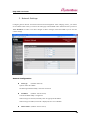
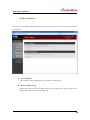
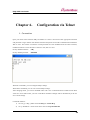
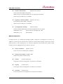
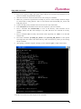
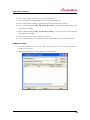
1
Eddy-CPU
User Guide
English Ver 0.9
March 23, 2007
Eddy-CPU User Guide
Revision History
Document
Revision Date
Version
March 20, 2007
1.0
Pages
Description
All
Initial release by jhkim
Copyright 2007 SystemBase Co., Ltd. All rights reserved.
Website
http://www.sysbas.com/
Tel
82-2-855-0501
Fax
82-2-855-0580
th
16 Fl. Daerung Post Tower-1, 212-8, Guro-dong, Guro-gu, Seoul, Korea
For any inquiries or comments, contact to [email protected]
2
Eddy-CPU User Guide
Contents
Chapter 1. Introduction
5
1. About This Document
5
2. Who Should Read This Document?
5
3. Document Structure
6
4. Eddy Documents
7
5. Technical Supports
8
Chapter 2. Getting Started
9
1. Overview
9
2. Features
12
3. Package Checklist
13
4. Applications
14
Chapter 3. Hardware Description
15
1. Overview
15
2. Eddy-CPU Development Kit
19
Chapter 4. Integration
25
1. Connection Guide
25
2. First-time Bootup
25
3. Connecting to Eddy with IP address
25
Chapter 5. Configuration via Web
28
1. Connection
28
2. Setup Menu
29
3. Network Settings
30
3
Eddy-CPU User Guide
4. Serial Settings
32
5. GPIO Settings
37
6. Admin Settings
38
7. Change Password
39
8. Update Firmware
40
9. Factory Default
41
10. Save & Reboot
42
Chapter 6. Configuration via Telnet
43
1. Connection
43
2. View Commands
44
3. Network Commands
44
4. Serial Commands
46
5. GPIO Commands
48
6. Username/Password Commands
48
7. System Commands
48
Chapter 7. Appendix
49
1. Firmware Update
49
1. Technical Specifications
53
2. Ordering Information
55
3. FCC Statement
55
4
Eddy-CPU User Guide
Chapter 1.
Introduction
This chapter is an introduction to SystemBase embedded CPU module Eddy-CPU.
1. About This Document
This guide is designed for users of Eddy-CPU, who are in charge of connecting to and communicating
with Eddy, setting Eddy’s configurations, status monitoring, firmware update, and other administration
work.
2. Who Should Read This Document?
This guide is designed for Eddy-CPU users and administrators. It is strongly recommended that anyone
trying to apply, use, and maintain Eddy read this document. This guide deals with the hardware-level
integration issues and software-level configuration tips. It will be a great starting point for any
administrators who want to easily monitor and control Eddy and its connected devices.
5
Eddy-CPU User Guide
3. Document Structure
Introduction (Chapter 1) is a preface with general information and introductory notices.
Getting Started (Chapter 2) presents a brief introduction about Eddy-CPU, including features and
applications.
Hardware Descriptions (Chapter 3) explains about the layout and pin specifications with block diagram
and drawings.
Integration (Chapter 4) helps you to connect Eddy to serial and network environment. It ends up with
first time boot-up and status check.
Configuration via Web (Chapter 5) provides menu-by-menu guide for setting up the operation
environment for Eddy via web browser.
Configuration via Telnet (Chapter 6) provides a list of commands for setting up the operation
environment for Eddy via Telnet.
Appendix (Chapter 7) provides firmware update guides and technical specifications for detailed
information.
6
Eddy-CPU User Guide
4. Eddy Documents
The following table summarizes documents included in the Eddy document set.
Document Name
Description
User Guide
Integration, configuration, and
management of Eddy-CPU
for the administrator
Programmer’s application development
guide, including in-depth approach to
compiling, linking, and creating firmware
Programmer’s Guide
API reference is also included with a
list of available functions
for customized application programming
Portview User Manual
Guide for SystemBase device server
management application Portview
COM Port Redirector
User Manual
Guide for SystemBase COM Port Redirector
If you need more information on Eddy-CPU or embedded device servers in general, please visit our
corporate website at http://www.sysbas.com/. You can view and/or download documents related to Eddy
as well as latest software and firmware updates. Available resources are as follows:
Document Name
Description
Eddy-CPU Spec Sheet
Specifications for Eddy-CPU
An introductory reading for anyone new
to embedded device server.
Eddy-CPU White Paper
Deals with background, history, market
environment, and technology
Eddy-CPU Application
Notes
Various applications of Eddy presented
in diagrams and images
All documents are updated promptly, so check for the recent document update. The contents in these
documents are subject to change without any notice in advance.
7
Eddy-CPU User Guide
5. Technical Supports
There are three ways you can get a technical support from SystemBase.
First, visit our website http://www.sysbas.com/ and go to ‘Technical Support’ menu. There you can read
FAQ and ask your own question as well.
Second, you can e-mail our technical support team. The mail address is [email protected]. Any kind of
inquiries, requests, and comments are welcome.
Finally, you can call us at the customer center for immediate support. Our technical support team will
kindly help you get over with the problem. The number to call is 82-2-855-0501.
8
Eddy-CPU User Guide
Chapter 2.
Getting Started
Welcome to Eddy! This chapter includes Eddy-CPU overview, main and distinctive features, package
contents for each product, and application fields.
1. Overview
Eddy-CPU is an Embedded Device Server module that comes with a Conexant CX82100-41Z processor,
SDRAM, Flash memory, one 10/100Mbps Ethernet port, 8 bit address/8 bit data bus interface to support
flexible connections to outer devices such as UART, and a maximum of 17 user programmable IOs. Users
can easily implement UART & 232/422/485, I2C interface and much more using example codes and
Evaluation Kit circuits.
Eddy-CPU comes in small form factor (38 x 22mm) but yet has an on board memory and integrated
10/100Mbps network interface which would enable minimized input of time and money for future
application developments.
[ Eddy-CPU module block diagram ]
9
Eddy-CPU User Guide
Eddy-CPU Development Kit
Eddy-CPU Development Kit provides an easy environment for the programmer to test their applications
on Eddy-CPU. Eddy-CPU Development Kit includes test board, various connectors, programming
environment and documents.
Refer to ‘Programming Guide’ included in the Eddy-CPU Development Kit for more detailed information.
Conexant CX82100
The Conexant™ CX82100 Home Network Processor (HNP) is a single-chip, 185 MIPS high performance,
ARM940T-based processor integrated with multiple network interface hardware functions and packaged
into a 196-pin FPBGA.
[ Processor Block Diagram ]
10
Eddy-CPU User Guide
Product at a Glance
Software Architecture
11
Eddy-CPU User Guide
2. Features
Various features of Eddy-CPU make it easy to apply Eddy-CPU to various application developments.
Main features are presented below. Other minor features will be explicitly presented throughout this guide.
-
Premium-level hardware with ARM940T 168MHz CPU, 4MB Flash, and 8MB SDRAM
-
Program and execute your own application
-
SystemBase SDK and API support for application programming (included in Development Kit)
-
Small sized to be integrated in any hardware (38.0 x 20.8 mm)
-
10/100Mbps Ethernet port (Exterior Transformer & RJ45 needs to be implemented)
-
SystemBase COM Port Redirector for better adaptability
-
Extensive configuration and monitoring with Portview
-
Firmware upload through Web, FTP, and TFTP
-
Configuration through Web, Telnet, SNMP, and Portview
-
Various customizing options
-
Standard Linux environment for openness in executable applications
-
Maximum 16 Programmable IO pins for customized applications
-
3.3V power input
12
Eddy-CPU User Guide
3. Package Checklist
Eddy-CPU package is composed of following components. Make sure every component is included with
your package.
Module
All module packages include a module and a CD with utilities and documents.
-
One Eddy-CPU Module
-
CD-ROM (utilities and documents)
Development Kit: Eddy-CPU DK
Eddy-CPU Evaluation Board
Eddy-CPU Module
Serial Cable 1pc (null modem cable)
LAN Cross Cable 1pc
USB Cable 1pc (for firmware download), jumper
Power Adaptor 1pc
Power Cable 1pc (Euro or US – selectable in order)
CD (SystemBase SDK, compile environment, documentations, etc.)
13
Eddy-CPU User Guide
4. Applications
Eddy-CPU can be applied to many practical applications in various fields. Here we present some of them.
Factory / Industrial Automation
PLC, Robot arms, Human-Machine Interface, Warehouse rails
Medical instruments, Inspection equipment controllers
Alarming units
Home Appliances / Electronic Devices
Power controller, Gaming machines
Scales, Gas detection units, Water & pollution metering devices
Data collection and distribution units
Financial / Building Automation
Card readers, Barcode scanners, Kiosks, Point-Of-Sale related devices
Serial printers, Cash registers, Credit card authorization terminals
Biometric detection units, Security devices
OEM Device Server Distributors
OEM device server with distributor’s own case & brand
Ready-to-go device or customized application / setup mode can be inserted
14
Eddy-CPU User Guide
Chapter 3.
Hardware Description
This chapter provides Eddy-CPU’s hardware information including block diagram, layout, pin
specifications, dimensions and other hardware-related issues.
1. Overview
Ethernet LAN port is provided as a pin-header. Transformers and RJ-45 connector must be implemented
exteriorly by the user. (or RJ connectors with internal transformer -- LAN-Mate or MACJack -- may be
use for implementations.)
8 bit address/8 bit data bus provides flexible connections to outer devices such as UART
8 bit address/8 bit data bus interface to support flexible connections to peripheral devices such as UART.
Maximum of 16 user programmable IOs are available.
This chapter provides Eddy’s hardware information, including block diagram, layout, pin specifications,
dimensions and other hardware-related issues.
Chip Selects
Chip select signal
Typical Slave Device
Address Range
Size
0x00400000CS0#
Flash ROM
4MB
0x007FFFFF
0x002C0000-
IO_CS#
Application dependent
64KB
0x002CFFFF
Eddy-CPU Operating Conditions
Parameter
Symbol
Min
Typ
Max
Units
Supply Voltage
Vcc
3.0
3.3
3.6
VDC
Supply Current
Icc
Operating ambient temperature
TA
400
0
mA
70
℃
15
Eddy-CPU User Guide
Eddy-CPU Board Layout
①
①
②
②
①①
Pin Descriptions
J1 Pin Description
Pin for Flash Programming. Insert pin jumper on J2 and connect J1 to USB cable. (Please refer to the
Programmer Guide for more information on flash programming).
Pin No
Name
1
USBN
Description
USBP and USBN are differential data positive and negative signals
for USB port. Connect USBP and USBN to USB +Date and USB –
2
USBP
Data.
3
GND
Connect to USBs GND
J2 Pin Description
Enables compiling, linking, creating and uploading of firmware to Eddy-CPU. Connect J1 to USB cable
while J2 is connected to a jumper.
J2 Jumper
ON
Internal Boot (USB Programming)
OFF
Flash Boot (Normal operation)
16
Eddy-CPU User Guide
J3, J4 Pin Description
J3
J4
Pin
Description
Pin
Description
Pin Description
Pin
Description
1
HA7
2
HA6
1
GPIO8
2
GPIO9
3
HA5
4
HA4
3
GPIO10
4
GPIO3
5
HA3
5
HA2
5
GPIO4
5
GPIO1
7
HA1
8
HA0
7
GPIO6
8
GPIO7
9
IO_CS#
10
IO_WR#
9
GPIO5
10
GPIO11
11
GND
12
IO_RD#
11
GPIO12
12
GPIO2
13
HRST#
14
HRST
13
IO_INT
14
GPIO13
15
HD7
16
HD6
15
GPIO14
16
GPIO15
17
HD5
18
HD4
17
GPIO16
18
GND
19
HD3
20
HD2
19
GND
20
NC
21
HD1
22
HD0
21
LAN_TX+
22
LAN_TX-
23
GND
24
3.3V
23
GND
24
GND
25
GND
26
3.3V
25
LAN_RX+
26
LAN_RX-
27
NC
28
NC
29
LED_100M
30
LED_10M
J3
Pin No
Name
Description
1~8
HA[7:0]
Address Line 0~7
9
IO_CS#
Exterior Device Chip Select Signal, active low signal
10
IO_WR#
Exterior Device Write Enable Signal, active low signal
11
GND
12
IO_RD#
Exterior Device Read Enable Signal, active low signal
13
HRST#
Reset Output Signal, active low
14
HRST
Reset Output Signal, active high
15~22
HD[7:0]
Ground
Data Line 0~7
17
Eddy-CPU User Guide
J4
Pin No
Name
1~17
GPIO[15:0]
13
IO_INT
20
NC
21
LAN_TX+
Description
Programmable General purpose Input/output 16ea
Exterior Device Interrupt Signal, input polarity selectable
No Connection, Must maintain Open status
Ethernet TX+, Ethernet Implementable by connecting to External
Transformer
Ethernet TX-, Ethernet Implementable by connecting to External
22
LAN_TXTransformer
Ethernet RX+, Ethernet Implementable by connecting to External
25
LAN_RX+
Transformer
Ethernet RX-, Ethernet Implementable by connecting to External
26
LAN_RXTransformer
When linked to 100Base-T, LED ON lightens up and blinks during data
29
LAN_100M
transmission. (When linked to 10Base-T, this LED does not light up.)
When linked to 10Base-T, LED ON lightens up and blinks during data
30
LAN_10M
transmission. (When linked to 100Base-T, this LED does not light up.)
18
Eddy-CPU User Guide
2. Eddy-CPU Development Kit
Block Diagram
19
Eddy-CPU User Guide
Development Kit Board Setup
The table below explains configuration of straps and jumper setting required for utilizing Eddy-CPU
Development Kit. For Eddy-S1/TTLs, be sure to check the input voltage label sticker on the board. J1
must be set to proper voltage shown on the label before power is supplied.
Æ For more information . please refer to DK manual.
Eddy-CPU & Eddy-S1/TTL DK Layout-Top View
-
Switch part (SW1)- Can configure the condition of interface
-
(RS-232/422/485) and device type( Eddy-CPU and
-
Eddy-S1/TTL) using deep switch. (Please refer to the table
-
on the upper part of the board for configuration methods)
Power Select jumper(J1) – Select 5V or 3.3V power
Reset Switch – only Eddy-S1/TTL
Power LED
20
Eddy-CPU User Guide
Configuration Straps and Jumper Settings
Designation
Setting
Feature
Eddy-S1/TTL input voltage is set to 3.3V
Eddy-S1/TTL can take in either 3.3V or 5V. Be sure to check the input
Power select
1-2
voltage label sticker on the board and set the jumper accordingly.
Jumper(J1)
(Eddy-CPU input voltage is set to 3.3v regardless of J1 settings.)
3-4
1
Eddy-S1/TTL input voltage is set to 5V
Serial Interface Configuration INF[1:0] = ‘00’ , RS232
INF1
INF[1:0] = ‘01’ , RS422
INF[1:0] = ‘10’ , RS485
2
INF0
Serial Interface Configuration applies only to Eddy-S1/TTL products.
Default setting(OFF) is configured to Eddy-CPU DK.
Determines output power of serial port.
3
TTL/CPU
When testing Eddy-S1/TTL , turn the switch ON.
Switch
Part
When testing Eddy-CPU DK , turn the switch OFF.
4
NC
No Connection
(SW1)
Termination Resistor can be installed when configuring RS422 mode.
If operating under RS422 mode, 485_TR must be switched to “OFF”.
5
422_TR
422_TR may be switched to “ON” depending on the existence of
termination resistors.
Termination Resistor can be installed when configuring RS85_mode.
If operating under RS485 mode, 422_TR must be switched to “OFF”.
6
485_TR
485_TR may be switched to “ON” depending on the existence of
termination resistors.
[ Eddy-CPU Configuration(RS232 Only) ]
[ Eddy-S1/TTL Configuration ]
21
Eddy-CPU User Guide
22
Eddy-CPU User Guide
23
Eddy-CPU User Guide
24
Eddy-CPU User Guide
Chapter 4.
Integration
This chapter explains how you can make Eddy-CPU to communicate. It deals with LAN and pin header
connection guides for Eddy-CPU to operate together with the target serial device.
1. Connection Guide
Follow these steps to connect Eddy to the device and network.
In order to connect Eddy to network, you need to use RJ45 Ethernet port. It supports both 10Mbps and
100Mbps Ethernet connection (auto-sensing). If you would like to connect Eddy-CPU development board
to PC directly, use a cross LAN cable. Otherwise, plug one end of a direct LAN cable to Eddy-CPU and
the other end to a hub, switch, or any other network device that can provide you with network access.
2. First-time Bootup
An IP address is required to access Eddy’s web interface or telnet command-line configuration tool. By
factory default, Eddy is assigned a static IP address. After the initial connection, you can either manually
assign a different IP address or set Eddy to automatically get an IP address from a DHCP server. While
this depends on your network environment and policy, it is strongly recommended that you assign
Eddy with a unique static IP.
3. Connecting to Eddy with IP address
The factory default IP address:
192.168.0.223
Eddy’s default IP address is set to 192.168.0.223. In order to connect with this address, you need to
change network configurations so that your PC can connect to the IP 192.168.0.223. Please refer to an
example below, and note that values don’t necessarily have to be identical to the example below.
25
Eddy-CPU User Guide
In case you configure Eddy to use DHCP to obtain an IP address automatically, you might find it hard to
know the IP address to connect to. To provide users with an easier way to know the current IP address,
Eddy has a fixed alias IP that is always accessible. Use the address below whenever you cannot find out
Eddy’s IP address.
Factory default alias IP address: 10.10.1.1
In order to connect with this address, you need to change network configurations so that your PC can
connect to the IP 10.10.1.1. Please refer to an example below, and note that values don’t necessarily have
to be identical to the example below.
Now you are ready to connect to Eddy! There are three options to configure Eddy.
Web: You can easily configure Eddy with web interface, accessible from any web browser. For more
information, please refer to Chapter 5. Configuration via Web.
Telnet: You can configure Eddy with commands after accessing Eddy through Telnet. For more
26
Eddy-CPU User Guide
information, please refer to Chapter 6. Configuration via Telnet.
Portview: You can use a Windows-based utility Portview from SystemBase to monitor Eddy. For more
information on using the utility for your administration purpose, please refer to Portview User Guide.
27
Eddy-CPU User Guide
Chapter 5.
Configuration via Web
1. Connection
Open your favorite web browser and enter the IP address of Eddy to access Eddy’s web manager. Once
you are successfully connected, the following front page will show up. You need to enter appropriate
username and password to login.
Please note that this username and password is used as authentication method for Telnet as well. This
means if username or/and password has been modified from the web interface, modified values have to be
entered to connect to Telnet, and vice versa.
Factory default username:
eddy
Factory default password:
99999999
28
Eddy-CPU User Guide
2. Setup Menu
If login process is successful, you will see a web manager’s main page, showing summary of your device.
On the left, you will see a setup menu, and you can navigate through these options.
Summary
: View a summary of Eddy.
Network Settings :
Configure network connection settings.
Serial Settings
Configure detailed operation environment for serial communication.
:
(You need an external UART circuit for this)
GPIO Settings
:
Admin Settings
: View and change device information and support information.
Change Password :
Configure programmable I/O pins.
Change ID and password for both Web and Telnet interface.
Update Firmware : Update Eddy’s firmware.
Factory Default
:
Restore all the factory default settings.
Save & Reboot
:
Save the configurations and reboot Eddy.
29
Eddy-CPU User Guide
3. Network Settings
Configure general network environment and network management. After changing values, you need to
click ‘Submit’ button. Then you will see the same page with modified values. Please note that you have to
‘Save & Reboot’ in order to see these changes in effect. Changes will be discarded if you do not save
current settings.
General Configuration
z
Line Type
(Default: Static IP)
Options: Static IP / DHCP
IP obtaining method for Eddy’s network connection
z
IP Address
(Default: 192.168.0.223)
Current IP address Eddy is assigned to.
When line type is Static IP, manually enter an appropriate IP address.
When line type is DHCP, current IP is displayed, but it is not editable.
z
Subnet Mask (Default: 255.255.255.0)
30
Eddy-CPU User Guide
Current subnet mask Eddy is assigned to.
When line type is Static IP, manually enter an appropriate subnet mask.
When line type is DHCP, current subnet mask is displayed, but it is not editable.
z
Gateway
(Default: 192.168.0.1)
Current default gateway Eddy is assigned to.
When line type is Static IP, manually enter an appropriate default gateway.
When line type is DHCP, current default gateway is displayed, but it is not editable.
z
SNMP
(Default: Disable)
Options: Enable / Disable
Enable or disable SNMP(Simple Network Management Protocol) support.
MIB-II (RFC 1213):
System, Interface, IP, ICMP, TCP, UDP
MIB-I (RFC 1317):
Serial Interface
NMS Configuration
If multiple devices are installed and managed together, integration in management is necessary. In
addition, it is often the case when the device reports an erroneous status, figuring out the reason for the
failure becomes a time-consuming job. To solve this inefficiency and provide better solution, Eddy
includes a Network Management System software, Portview.
z
NMS Server IP / Port (Default: 0.0.0.0 / 4000)
Set the IP address and the port number of the PC where Portview in installed. For more
information on Portview, please refer to the Portview User Manual.
If IP is set to 0.0.0.0, NMS feature is disabled.
z
Device Name (Default: Eddy-1/Pin)
Set the device name for management. 32 Characters at maximum.
z
Group
(Default: None)
Set the group name for management. 32 Characters at maximum.
z
Location
(Default: None)
Set the location name for management. 32 Characters at maximum.
31
Eddy-CPU User Guide
4. Serial Settings
This part will be used by user who wants to use serial port with external UART. If you don’t want to use
serial port , you don’t need to see this part.
You can set the communication and operation environment for the serial port. After changing values, you
need to click ‘Submit’ button. Then you will see the same page with modified values. Please note that you
have to ‘Save & Reboot’ in order to see these changes in effect. Changes will be discarded if you do not
save current settings.
z
Status
(Default: Enabled)
Options: Enabled / Disabled
Choose to use or not use this port.
32
Eddy-CPU User Guide
z
Interface
(Default: RS232)
Options: RS232 / RS422 / RS485
Current serial interface type is displayed. Refer to Chapter 3. Hardware for detailed
information on changing serial interface type.
z
Operation Mode (Default: COM(Win200x/XP))
Select the operation protocol, which the serial port would use.
J
COM(Win200x/XP)
Use the serial port of Eddy as the COM ports of Windows 2000/XP/2003 operated PC.
(Both the data and the signal line information of the serial port can be controlled.)
J
COM(Win98/ME)
Use the serial ports of Eddy as the COM ports of Windows 98/ME operated PC. (Both the
data and the signal line information of the serial port can be controlled.)
J
TCP Server
Eddy works as a socket server, waiting for the client connection on the network.
Socket number for awaiting connections can be set in ‘Local socket port’ field.
All data between the socket and the serial port is transferred untouched after the socket
connection is established.
J
TCP Client
Eddy acts as a socket client in this mode. It tries to connect to the server IP address and
the socket number assigned when a certain server waits for connection on the network.
All data between the socket and the serial port is transferred untouched after the socket
connection is established.
J
TCP Multi-Server
Eddy works as a server, accepting up to 5 simultaneous connections from socket clients.
Data transmitted from Eddy is broadcast to each socket client.
J
UDP Server
Eddy works as a UDP server, waiting for UDP connection from the client on the network.
Socket number for awaiting connections can be set in ‘Local socket port’ field.
Once a UDP packet is received to the socket that waits for the connection, the data is
transmitted to the serial port. The data input from the serial port is put into UDP packets,
which eventually are sent to the client.
J
UDP Client
When the data is input to the serial port, UDP packets are sent using the preset IP address
and the socket number of the server.
33
Eddy-CPU User Guide
z
Local Socket Port
(Default: 4001)
Set the socket number for the port. TCP server and UDP server operation mode makes use of
this port for awaiting network socket connections.
z
Port Alias
(Default: Port1)
Port alias name for convenience. 16 Characters at maximum.
z
Baud Rate
(Default: 9600bps)
Options: 150, 300, 600, 1200, 2400, 4800, 9600, 19200, 38400, 57600, 115200, 230400,
460800, 921600bps
Set communication speed.
z
Data Bits
(Default: 8)
Options: 5, 6, 7, 8
Set the number of bits in each character size.
z
Stop Bits
(Default: 1)
Options: 1, 2
Set the number of stop bits.
z
Parity
(Default: None)
Options: None, Odd, Even
Set parity bit check scheme.
z
Flow Control (Default: None)
Options: None, Xon/Xoff, RTS/CTS
Set the flow control scheme.
z
Device Type (Default: DataOnly)
Options: Data Only, Modem Signals
Set the signal line checking method for the device to be connected to the given serial port.
If the mode is set to Data Only, only Txd, Rxd, and Gnd signal lines are used in inter-device
communication. If the mode is set to Modem Signals, all modem signals except RI(Ring
Indicator) are asserted, tested, and used in communication.
34
Eddy-CPU User Guide
z
Remote IP Address / Port
(Default: 0.0.0.0 / 4000)
When the Operation Mode is either TCP Client or UDP Client, set the IP address and the
socket number to connect to.
z
Alive Check Time
(Default: 0 sec)
After a certain amount of time passes without any communication after the socket connection
between the given serial port and the server is established, automatically disconnect the socket
connection. Valid from 0 to 32767.
For example, if the operation mode is set to TCP Server and Alive Check Time is configured
to 10, TCP Server will listen for the client’s connection and eventually establish a connection.
Since the check time is 10 seconds, the server will wait for 10 seconds until the client
connected to it sends any packet. If there is no data for 10 seconds, server will quit the
connection and return to the listening state. This option is helpful in preventing
communication obstacles that occur when either Eddy or the client quits unexpectedly (i.e.
Sudden black out, reboot, LAN cable cut, etc.). In these cases, the other part of communication
might not recognize the failure of its partner. Such misunderstanding can cause
communication errors.
If the value is set to 0, this function is disabled. Once connected socket will be retained until
explicitly disconnected.
(Only applies to TCP Client, TCP Server, TCP Multi-Server operation modes.)
z
MTU
(Default: 1 byte)
MTU stands for Maximum Transmission Unit, and this option needs to be set when
consecutive data from the given serial port needs to be transmitted to socket at once. If 100
bytes of character string are to be transmitted from the serial device and MTU is set to ‘100’,
Eddy waits until the entire 100 bytes are received. After receiving 100 bytes, it transmits this
data to the server as a single packet, using the socket. If 200 bytes of character string are to be
transmitted from the serial device, Eddy breaks this data into 2 packets of 100 bytes. If data
less than 100 bytes is received, Eddy will wait for a certain amount of time. While the duration
is determined by the communication speed, it normally is around 20 msec. If there is no
further data incoming during this time, Eddy will send what is stored until then, though not a
35
Eddy-CPU User Guide
full 100-byte data it may be, as one packet.
If MTU is set to ‘1’, however, each byte is transmitted right away in a packet, therefore
multiple packets sent to the server. Valid from 1 to 1100.
z
Port Login (Default: Disable)
Options: Enable, Disable
When the Operation Mode is set to TCP Server, ask for the username and password when the
client tries to connect.
z
Passive Username (Default: conuser)
When the Operation Mode is set to TCP Server, set the username to ask for. 32 Characters at
maximum.
z
Passive Password (Default: 99999999)
When the Operation Mode is set as TCP Server, set the password to ask for. 32 Characters at
maximum.
36
Eddy-CPU User Guide
5. GPIO Settings
Configure operation mode and value for each Programmable I/O pins.
Eddy includes 9 GPIO pins that output 3.3V or detect 3.3V signals. You can detect either any 3.3V signals
from external device, or output 3.3V signal to the external device. You can also program a customized
GPIO application, and you can implement it with the SDK included in the Eddy development kit.
After changing values, you need to click ‘Submit’ button. Then you will see the same page with modified
values. Please note that you have to ‘Save & Reboot’ in order to see these changes in effect. Changes will
be discarded if you do not save current settings.
z
Mode (Default: Output)
Options: Output, Input
Set current pin’s I/O mode. When in output mode, 3.3V output can be controlled. When in
input mode, any 3.3V from outside can be detected.
37
Eddy-CPU User Guide
z
Value (Default: High)
Options: High / Low
Set current pin’s output value. (This option only applies to output mode pins)
If the value is High, 3.3V is output through the port.
6. Admin Settings
Device information and support information settings. After changing values, you need to click ‘Submit’
button. Then you will see the same page with modified values. Please note that you have to ‘Save &
Reboot’ in order to see these changes in effect. Changes will be discarded if you do not save current
settings.
Device Information
z
Device Name (Default: Eddy-1/Pin)
Name of the current device.
z
Firmware Version
Current firmware version.
38
Eddy-CPU User Guide
z
Hardware Version
Current hardware version.
z
Kernel Version
Current kernel version.
Support Information
z
Website
Website for help and support.
z
Contact
Contact information for technical support.
7. Change Password
Change Web/Telnet access username and password. After changing values, you need to click ‘Submit’
button. Then you will see the same page with modified values. Please note that you have to ‘Save &
Reboot’ in order to see these changes in effect. Changes will be discarded if you do not save current
settings.
As stated before, default username and password are eddy and 99999999, respectively.
39
Eddy-CPU User Guide
8. Update Firmware
Firmware is an application embedded in Flash memory of Eddy. Set the location of the firmware file to
update, using the ‘Browse…‘ button. The selected firmware will be transferred to Eddy when you click
‘Start Update’. After the transmission is complete, Eddy will be automatically restarted to operate with
the new firmware. Recent firmware can be downloaded at the SystemBase web site,
http://www.sysbas.com/
40
Eddy-CPU User Guide
9. Factory Default
Restore all the configuration parameters to the factory default values. Clicking on ‘Restore Factory
Defaults’ button will delete all current settings and restore settings to the initial status. Eddy will
automatically reboot. You cannot turn back the decision once you select this option.
41
Eddy-CPU User Guide
10. Save & Reboot
This option saves changes to the Flash memory and restarts the system to let the changes to take place in
the operation.
z
Save and Reboot
‘Save & Reboot’ reboots Eddy after saving changes to Flash memory.
z
Reboot without Saving
‘Reboot Only’ option just reboots Eddy without saving changes. This option can be used to
rollback the changes you have mistakenly made.
42
Eddy-CPU User Guide
Chapter 6.
Configuration via Telnet
1. Connection
Open your telnet client and enter Eddy’s IP address to connect. You need to enter appropriate username
and password to login. Please note that this username and password is used as authentication method for
Web as well. This means if username or/and password has been modified from the telnet interface,
modified values have to be entered to connect to web, and vice versa.
Factory default username:
eddy
Factory default password:
99999999
With ‘set’ commands, you can configure Eddy’s settings.
With ‘view’ commands, you can view current Eddy’s settings.
After changing values, you can see modified values with ‘view’ commands. But be careful because these
values are not in effect unless you issue a ‘set save’ command. Changes will be discarded if you do not
save current settings.
Command notations:
1) set line [ ip / dhcp ]: Either enter set line ip or set line dhcp.
2) set ip <IP address>: Enter actual values such as set ip 192.168.0.223
43
Eddy-CPU User Guide
2. View Commands
z
view
Show summarized information about Eddy.
z
view all
Show all available information about Eddy.
z
view server
Show network and device server’s settings.
z
view port
Show serial port settings.
z
view gpio
Show GPIO pin settings.
z
view version
Show version and support information.
z
view command
Show ‘set’ command list.
z
view help
Show ‘view’ command list.
3. Network Commands
Configure general network environment and network management.
General Configuration
z
set line [ ip / dhcp ]
(Default: Static IP)
IP obtaining method for Eddy’s network connection
z
set ip <IP Address>
(Default: 192.168.0.223)
Set the current IP address Eddy is assigned to.
When line type is Static IP, manually enter an appropriate IP address.
When line type is DHCP, it is not editable.
44
Eddy-CPU User Guide
z
set mask <Subnet mask>
(Default: 255.255.255.0)
Set the subnet mask Eddy is assigned to.
When line type is Static IP, manually enter an appropriate subnet mask.
When line type is DHCP, it is not editable.
z
set gateway <Gateway address> (Default: 192.168.0.1)
Set the default gateway Eddy is assigned to.
When line type is DHCP, it is not editable.
z
set snmp [Enable / Disable]
(Default: Disable)
Enable or disable SNMP(Simple Network Management Protocol) support.
MIB-II (RFC 1213):
System, Interface, IP, ICMP, TCP, UDP
MIB-I (RFC 1317):
Serial Interface
NMS Configuration
If multiple devices are installed and managed together, integration in management is necessary. In
addition, it is often the case when the device reports an erroneous status, figuring out the reason for the
failure becomes a time-consuming job. To solve this inefficiency and provide better solution, Eddy
includes a Network Management System software, Portview.
z
set nms <IP address>
(Default: 0.0.0.0)
If IP is set to 0.0.0.0, NMS feature is disabled.
z
set nport <Port number> (Default: 4000)
NMS socket number (if NMS is used)
z
set name
(Default: Eddy-1/Pin)
Set the device name for management. 32 Characters at maximum.
z
set group
(Default: None)
Set the group name for management. 32 Characters at maximum.
z
set location
(Default: None)
Set the location name for management. 32 Characters at maximum.
45
Eddy-CPU User Guide
4. Serial Commands
You can set the communication and operation environment for the serial port. Chapter 5 describes each
option in detail. Only a summary of each option is presented here.
z
set port 1 status [Enable / Disable]
(Default: Enable)
Choose to use or not use this port.
z
set port 1 protocol [com2kxp / com98 / tcp_server / tcp_client / tcp_mserver /
udp_server / udp_client]
(Default: com2kxp)
Select the operation protocol, which the serial port would use.
z
set port 1 <port number>
(Default: 4001)
Set the socket number for the port. TCP server and UDP server operation mode makes use of
this port for awaiting network socket connections.
z
set port 1 name <name>
(Default: Port1)
Port alias name for convenience. 16 Characters at maximum.
z
set port 1 speed [150 / 300 / 600 / 1200 / 2400 / 4800 / 9600 / 19200 / 38400 / 57600 /
115200 / 230400 / 460800 / 921600]
(Default: 9600bps)
Set communication speed.
z
set port 1 data [5 / 6 / 7 / 8]
(Default: 8)
Set the number of bits in each character size.
z
set port 1 stop [1 / 2]
(Default: 1)
Set the number of stop bits.
z
set port 1 parity [none / odd / even]
(Default: none)
Set parity bit check scheme.
z
set port 1 flow [none / xon / rts]
(Default: none)
Set the flow control scheme.
46
Eddy-CPU User Guide
z
set port 1 signal [data / modem]
(Default: data)
Set the signal line checking method for the device to be connected to the given serial port.
z
set port 1 remote <IP address>
(Default: 0.0.0.0)
When the Operation Mode is set to TCP Client, set the IP address to connect to.
z
set port 1 rport <socket number> (Default: 4000)
When the Operation Mode is set to TCP Client, set the socket number to connect to.
z
set port 1 keepalive <0 ~ 32767> (Default: 0 sec)
After a certain amount of time passes without any communication after the socket connection
between the given serial port and the server is established, automatically disconnect the socket
connection. If the value is set to 0, this function is disabled.
z
set port 1 mtu <1 ~ 1100>
(Default: 0)
MTU stands for Maximum Transmission Unit, and this option needs to be set when
consecutive data from the given serial port needs to be transmitted to socket at once.
z
set port 1 uselogin [0 / 1]
(Default: 0-Disable)
When the Operation Mode is set to TCP Server, ask for the username and password when the
client tries to connect. Set to 1 to enable.
z
set port 1 conusername <username>
(Default: conuser)
When the Operation Mode is set to TCP Server, set the username to ask for.
z
set port 1 conpassword <password>
(Default: 99999999)
When the Operation Mode is set as TCP Server, set the password to ask for.
47
Eddy-CPU User Guide
5. GPIO Commands
Configure operation mode and value for each Programmable I/O pins.
z
set gpio <0~15> mode [in / out] (Default: Output)
Set current pin’s I/O mode.
z
set gpio <0~15> value [low / high] (Default: High)
Set current pin’s output value. (This option only applies to output mode pins)
6. Username/Password Commands
Configure username and password for Web/Telnet.
z
set user <username> (Default: eddy)
Set username. 16 Characters at maximum.
z
set pass <password> (Default: 99999999)
Set password. 16 Characters at maximum.
7. System Commands
z
set default
Restore all settings to factory default. Requires reboot for changes to take effect.
z
set save
Save current configuration settings. Requires reboot for changes to take effect.
z
reboot
Reboot Eddy.
48
Eddy-CPU User Guide
Chapter 7.
Appendix
1. Firmware Update
Eddy supports firmware update with Web, FTP, and TFTP. This section describes update method via FTP
and TFTP. Web update is described in Chapter 5. Configuration via Web.
You can get the firmware in System base Home page dataroom (www.sysbas.com).
Update via FTP
<You may not see the exact same output for all commands>
49
Eddy-CPU User Guide
1.
First of all, connect to Eddy with Telnet. Enter eddy for the username and 99999999 for the
password. (When using the default settings)
2. After the connection, activate the FTP service with ‘set ftp on’ command.
3. Make sure you have the right firmware of Eddy on your PC. In this example, firmware images
are stored under C:\eddy_firmware. Here we use firmware files named Eddy_FS_10c.bin and
Eddy_KR_10c.bin.
4. Connect to Eddy via ftp command. You can also use GUI-style FTP clients.
5. Enter anonymous for username. Password is not required, so just leave it blank.
6. Issue a command ‘cd /var/home/eddy’ to move to the directory where firmware can be
uploaded. Please note that write attempts to any other directories are restricted for security
reasons.
7. Issue a command ‘bin’ for binary file transfer mode. Optionally use ‘hash’ to see the data
transfer mark.
8. Issue both commands ‘put Eddy_FS_10c.bin’ and ‘put Eddy_KR_10c.bin’ to start upload.
The image files must reside in the same directory with current directory where you are running
the ftp command.
9. After getting a ‘Transfer complete’ message, issue a command ‘quit’ or ‘bye’ to disconnect.
<You may not see the exact same output for all commands>
50
Eddy-CPU User Guide
10. Now connect to Eddy with Telnet, if you are not connected.
11. Issue a command ‘cd /var/home/eddy’ to move to the upload directory.
12. Issue a command ‘ls’ to make sure firmware files are both successfully uploaded.
13. Issue a command ‘fcp -v Eddy_KR_10c.bin /dev/mtd2’ to write the new kernel image to the
Flash memory of Eddy.
14. Issue a command ‘fcp -v Eddy_FS_10c.bin /dev/mtd3’ to write the new file system image to
the Flash memory of Eddy.
15. Check if Erase / Write / Verify process is successful.
16. Issue a command ‘exit to close the telnet window, and reset Eddy to start with new firmware.
Update via TFTP
1.
You need a TFTP server on your PC. There are various freeware, so install any TFTP server
software of your choice.
2.
Make sure the firmware file is included in the current directory.
51
Eddy-CPU User Guide
3.
Now connect to Eddy with Telnet.
4.
Enter your username and password.
5.
After receiving a prompt, issue a command
‘tftp –g –l firmware –r Eddy_GN_10a.bin 192.168.0.45’ where –l firmware refers to the local
firmware location (Eddy) and –r Eddy_GN_10a.bin refers to the firmware filename that is in
TFTP Root directory at TFTP server (PC). The last argument is the TFTP server’s IP address
(PC).
6.
You get no output if TFTP transmission is successful.
7.
Move to the directory where the firmware is downloaded, and issue a command ‘ls’ to make
sure uploaded firmware file resides in this directory.
8.
Issue a command ‘upfirm firmware’ to start writing a new firmware to the memory.
9.
Check if Erase / Write / Verify process is successful.
10. Issue a command ‘reboot’ to reset Eddy with a new firmware.
52
Eddy-CPU User Guide
1. Technical Specifications
Specifications
Network
Protocols
TCP, UDP, Telnet, SSH, SSL/TLS, DDNS, ICMP, DHCP,
TFTP, HTTP, SNMP 1 & 2
LAN Port
10/100Mbps PHY * 1 (External transformer and RJ45 port required)
Connection Type
Static IP, DHCP
Hardware
Processor
32-bit ARM9 Processor with 168MHz
Flash Memory
4 MB
SDRAM
8 MB
GPIO (Programmable IO)
Max 16
LED
None
Power Input
3.3V
Power Consumption
1.3W
Dimensions
38.0 x 20.8mm
Weight
10g
Serial
only when you plan to implement a customized UART circuit for serial connectivity
Environmental
Operating Temp.
0 ~ 50˚C
Storage Temp.
-20 ~ 80˚C
Humidity
5 ~ 95% Non-Condensing
Software
O/S
Embedded Linux (Kernel 2.4.x)
Mgmt. Tools
SNMP, Portview, Web
Configuration
Telnet, Web, Portview
Security
Telnet, Web ID/Password, SSH, SSL/TLS
53
Eddy-CPU User Guide
Application Upload
TFTP, FTP, Web
Web Service
Embedded Web Server
COM Port Redirection
SystemBase COM Port Redirector for Windows 98/ME/2K/XP/2003
Approvals
CE Class A, FCC Class A, RoHS compliant
54
Eddy-CPU User Guide
2. Ordering Information
Eddy-CPU
Embedded CPU module w/programmability & 3.3V power
(Pin Header interface)
3. FCC Statement
THIS DEVICE COMPLIES WITH PART 15 OF THE FCC FULES. OPERATION IS SUBJECT TO
THE FOLLOWING TWO CONDITIONS: (1) THIS DEVICE MAY NOT CAUSE HARMFUL
INTERFERENCE, AND (2) THIS DEVICE MUST ACCEPT ANY INTERFERENCE RECEIVED,
INCLUDING INTERFERENCE THAT MAY CAUSE UNDESIRED OPERATION.
FCC RF
INTERFERENCE STATEMENT
NOTE:
This equipment has been tested and found to comply with the limits for a Class A digital device, pursuant
to part 15 of the FCC Rules. These limits are designed to provide reasonable protection against harmful
interference when the equipment is operated in a commercial environment. This equipment generates,
uses, and can radiate radio frequency energy and, if not installed and used in accordance with the
instruction manual, may cause harmful interference to radio communications. Operation of this
equipment in a residential area is likely to cause harmful interference in which case the user will be
required to correct the interference at his own expense.
55