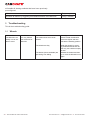
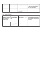
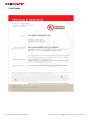
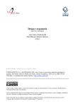
1
Looks Small, Performs Big
Technical Manual of Micro Data Center
www.canovate.com l [email protected] l P. +90 216 484 2222
Technical Manual of Micro Data Center l 1
Canovate Legal Disclaimer
The information presented in this manual is not
warranted by the Canovate to be authoritative, error
free, or complete. This publication is not meant to be
a substitute for a detailed operational and site specific
development plan. Therefore, Canovate assumes no
liability for damages, violations of codes, improper
installation, system failures, or any other problems
that could arise based on the use of this Publication.
The information contained in this Publication is
provided as is and has been prepared solely for
the purpose of evaluating data center design and
construction. This Publication has been compiled in
good faith by Canovate. However, no representation
is made or warranty given, either express or implied,
as to the completeness or accuracy of the information
this Publication contains.
IN NO EVENT SHALL CANOVATE, OR ANY PARENT,
AFFILIATE
OR
SUBSIDIARY
COMPANY
OF CANOVATE CORPORATION OR THEIR
RESPECTIVE OFFICERS, DIRECTORS, OR
EMPLOYEES BE LIABLE FOR ANY DIRECT,
INDIRECT,
CONSEQUENTIAL,
PUNITIVE,
SPECIAL, OR INCIDENTAL DAMAGES (INCLUDING,
WITHOUT LIMITATION, DAMAGES FOR LOSS
OF BUSINESS, CONTRACT, REVENUE, DATA,
INFORMATION, OR BUSINESS INTERRUPTION)
RESULTING FROM, ARISING OUT, OR IN
CONNECTION WITH THE USE OF, OR INABILITY
TO USE THIS PUBLICATION OR THE CONTENT,
EVEN IF CANOVATE CORPORATION HAS BEEN
EXPRESSLY ADVISED OF THE POSSIBILITY
OF SUCH DAMAGES. CANOVATE RESERVES
THE RIGHT TO MAKE CHANGES OR UPDATES
WITH RESPECT TO OR IN THE CONTENT OF THE
PUBLICATION OR THE FORMAT THEREOF AT
ANY TIME WITHOUT NOTICE.
Copyright, intellectual, and all other proprietary rights
in the content (including but not limited to software,
audio, video, text, and photographs) rests with
Canovate or its licensors. All rights in the content not
expressly granted herein are reserved. No rights of
any kind are licensed or assigned or shall otherwise
pass to persons accessing this information.
This Publication shall not be for resale in whole or in
part
www.canovate.com l [email protected] l P. +90 216 484 2222
Technical Manual of Micro Data Center l 3
Important Note
This manual contains essential system &
safety information, before beginning any work
involving the installation of a MicroDC system,
please read this manual.
When installation is complete please keep this
manual in a safe and available place.
We recommend that the installation and
maintenance of MicroDC systems should only
be carried out by suitably qualified personnel
who have been trained accordingly.
This product is classed as
“NOT USER SERVICEABLE”
The use of non-recommended spares or parts
or attempts at installing or servicing other than
described herein will invalidate conformity and
any valid warranty.
Copyright Notice
This document and the information that it
contains is the property of Canovate Group. Any
duplications or copies of this document should
be done so only with the written permission of
Canovate Group.
Please Recycle
4 l Technical Manual of Micro Data Center
www.canovate.com l [email protected] l P. +90 216 484 2222
Shipping materials are recyclable. Please
save them for later use or dispose of them
appropriately.
© Copyright 2008 Canovate
Canovate® is a registered trademark of Canovate
www.canovate.com l [email protected] l P. +90 216 484 2222
Technical Manual of Micro Data Center l 5
Technical Manual of
MicroDC
Table of Contents
Important Safety Instructions
7
1
Scope
8
2
Pre-installation precautions
9
2.1
Cabinet
9
2.2
Cooling unit
10
2.3
Ethernet
11
2.4
Mains Power Supply Line
12
3.
Installation
12
3.1
Required Setup Equipment
12
3.2
Cabinet Installation
13
3.2.1
Unpacking the MicroDC
13
3.2.2
General Information about Cabinet First
Installation or Relocation
16
3.2.3
Internal Mounting Rails
16
3.2.4
Mounting Hardware
17
3.2.5
Bonding Several MicroDCs together
19
3.3
Cooling Unit
19
3.4
Secondary Equipment
21
3.4.1
PDU
21
3.4.2
Fire Suppression
22
3.4.3
Access Control
23
3.4.4
UPS
23
3.4.5
EMS
26
3.4.6
LAN
27
4
Maintenance
28
4.1
Cooling device
28
4.2
Fire Suppression
28
4.3
UPS device
29
4.4
EMS device
29
5
Troubleshooting
30
5.1
Wheels
30
5.2
Cooling
31
5.3
Fire Suppression
32
5.4
Access Control
34
5.5
UPS
35
6
Service Log
37
7
Certificates
38
8
Notes
41
9
Contact Information
41
6 l Technical Manual of Micro Data Center
www.canovate.com l [email protected] l P. +90 216 484 2222
Important Safety Instructions
This manual contains important instructions that should
be closely followed during installation and maintenance of
this unit. Read all safety and operating instructions before
attempting to operate the MicroDC. Adhere to all warnings
on the unit and in this manual. Follow all operating and user
instructions.
This product is designed for commercial / industrial use only.
This product is not intended for use with life support.
Maximum heat load or weight load must not exceed those
shown on the rating label.
Operate this product in an indoor environment at an ambient
temperature of 00°C to 60°C with a relative humidity of 20%
to 85% (no condensing). Install in a clean environment, free
from dust, moisture, flammable liquids, gases, and corrosive
substances.
Where applicable, this product must be permanently connected
and powered from a suitable single-phase AC supply rated in
accordance with the equipment data plate. It must be suitably
grounded and protected by a circuit breaker or fuse. A residual
current device (commonly known as differential relay) must
be present in order to protect any engineer while installing,
maintaining or operating the MicroDC.
Ensure the MicroDC has proper ventilation. Never block or
insert objects into the ventilation holes or other openings.
Maintain a minimum clearance of 500mm in front, rear and
top of the MicroDC for proper air flow and cooling.
www.canovate.com l [email protected] l P. +90 216 484 2222
Technical Manual of Micro Data Center l 7
1 Scope
The scope of this technical manual includes four phases; first
it relies on helping the end user arrange / prepare the site
where the MicroDC is going to be installed. Second it explains
how the MicroDC should be properly handled, installed,
connected and operated. Third there is a maintenance guide
showing the maintenance procedure needed to be followed
in order to extend the MicroDC operating life. Forth there is
a troubleshooting guide on how to handle possible misuses
or other issues including a detailed FAQ (Frequently Asked
Questions) table.
8 l Technical Manual of Micro Data Center
www.canovate.com l [email protected] l P. +90 216 484 2222
2 Pre-installation precautions
2.1 Cabinet
MicroDC cabinet is coming in multiple versions in terms of
fixing. This information is usually pre-defined at the ordering
procedure. It usually comes as floor standing with or without
wheels. This means that you don’t have to worry about fixing
the cabinet on the floor. The wheels, whenever they are
present, they usually help the cabinet to move easily so the
system gains a portable character. In such cases that the
ordered MicroDC has no wheels, the standing place is very
important and should be initially decided, as later on it will
be very difficult but also dangerous and not recommended to
move.
When the MicroDC is ordered as wall mounted type then there
are no wheels attached; instead of wheels there is a specially
designed hanging supporter mechanism. This supporter
mechanism is used to hang the total cabinet on the wall.
Note: If you have ordered the wall mounted type please refer
to the respective installation guide for more information on
how to be prepared for the installation on the wall.
www.canovate.com l [email protected] l P. +90 216 484 2222
Technical Manual of Micro Data Center l 9
2.2 Cooling unit
Attached to the MicroDC there is an Air-Condition unit.
Usually this unit comes on the top of the cabinet and less
frequently on the door. This information is usually pre-defined
at the ordering procedure. The cooling unit has been already
attached onto the cabinet and already cabled.
There are two ways to connect the power feed to the cooling
unit. One way is to feed the cooling unit from any existing
PDU or IP-PDU inside the MicroDC. This option is used
whenever the administrator needs to control or check the
power consumption of the cooling unit. But this might stress
the PDU or any other equipment since the cooling unit comes
in two versions; version one is 2KW cooling capacity, version
two is 4KW cooling capacity. The second way is to feed the
cooling unit from a dedicated power line from any available
electrical distribution panel. It is strongly recommended to use
the second option and feed the system by a separated power
line.
In chapter 4.3 there is brief explanation on what kind of circuit
breaker shall be used but also all technical information in
regards to the power consumption / absorbed by the Mains
power network.
The condensate which, depending on the ambient temperature
and humidity conditions, forms on the exchanger that cools the
enclosure air is not a malfunction but a normal phenomenon
of the cooling unit. The condensate is taken outside the
MicroDC through two special metal tubes, a service tube and
an emergency one, located on the side of the cooling unit.
10 l Technical Manual of Micro Data Center
www.canovate.com l [email protected] l P. +90 216 484 2222
The MicroDC comes with 1,5m + 2,5m length special PVC
hoses (12mm inner Ø and 17mm outer Ø dimensions). These
pipes should be connected to both two tubes and should be
driven to the first available drain (gutter or spout). If the first
drain is more than 2 meters away from the MicroDC, then the
installer might need to extend these PVC hoses.
Please take great care to choose the most proper position
to place your MicroDC. You should choose a well-ventilated
place. For example a good choice is inside a room with an
open window or inside an air condition room. The MicroDC
should not be exposed to any possible drops of water coming
from the open window. When the cooling device is operating,
the generated noise (mainly coming from the embedded
compressor) might be annoying. Please avoid placing the
MicroDC close to any infants. Please visit the room where
the MicroDC stands quite often (especially after the first
installation) to secure that the environmental conditions meet
the operating limits.
2.3 Ethernet
According to the MicroDC configuration it might be equipped
with active equipment including Ethernet connectivity. In order
the administrator user to access remotely that equipment and
work out with it either controlling or simply monitor it then
a basic LAN port providing at least Ethernet cable cat-5e
should be available next to the place that the MicroDC will be
installed.
www.canovate.com l [email protected] l P. +90 216 484 2222
Technical Manual of Micro Data Center l 11
2.4 Mains Power Supply Line
A clean, unloaded and direct single phase power supply
line shall be present to supply all the power needed for the
equipment to be connected to the MicroDC. This line shall be
protected from spikes or surges through protection devices.
A residual current device must be present in order to detect
ground faults - leakage of current to somewhere other than
the neutral and line wires (like the ground wire or a person).
This device shall protect any engineer while installing or
while maintenance procedures. The line shall be protected
by the use of Circuit breakers and fuses to detect short
circuits between the line and neutral wires, or the drawing
of more current than the wires are rated to handle to prevent
overheating and fire. In order to calculate all these devices
the installer must be well informed in advance about the total
Load of the equipment to be installed to MicroDC. Information
regarding the electrical power absorbed by the cooling unit
can be found in the Cooling section.
3 Installation
All the installation must be held by professional engineers and
previously been trained to properly handle the MicroDC.
Note: The MicroDC is not intended to be used in an occupied
office environment, due to potentially high noise levels during
the cooling operation. Install the MicroDC in a computer room
or in any other room where people are normally present only
for maintenance.
3.1 Required Setup Equipment
The following tools are required to set up your MicroDC:
• Pallet jack
• Utility knife
• Allen key number 4 ratchet or wrench
• Torx screwdriver T25 ratchet or wrench
12 l Technical Manual of Micro Data Center
www.canovate.com l [email protected] l P. +90 216 484 2222
• Measuring tape and pen marker able to write on metal
surfaces
• Spirit Level
• hammer
• Flathead and Phillips screwdrivers
3.2 Cabinet Installation
CAUTION:
Be sure to read and understand the documentation that
comes with the cabinet for safety and cabling information. Also
make sure that you read and understand all the related safety
information for all the equipment and review the guidelines in
this publication before you install any device into the MicroDC
cabinet. Reading and understanding all information reduces
the risk of personal injury and or damage to your newly
received product.
3.2.1 Unpacking the MicroDC
Upon receiving your MicroDC, please examine the packaging
for any signs of mishandling or damage. If any damage is
noted, shoot some pictures or a short video and then please
notify Canovate Group and your carrier as well. Do not
attempt to continue the unpacking unless otherwise advised.
Remember that the Limited Warranty is not valid whenever a
transportation mishandling has damaged the MicroDC.
The MicroDC is standing on a wooden pallet. All the way
round there are lots of thick cartons used for protection of the
cabinet against possible damage to the surface color. Overall
these carton vertical lines there is nylon or bubble nylon used
for protection against dust, insects or any other small similar
intrusions.
www.canovate.com l [email protected] l P. +90 216 484 2222
Technical Manual of Micro Data Center l 13
Step 1:
Remove all wooden pcs or wooden box (whenever
it is present in the packaging contents). You might
need to use a Phillips screwdriver and a hammer.
Step 2:
Remove the nylon slowly and gently using the
utility knife or any other suitable cutting tool;
take care not to scratch the color of the MicroDC
cabinet.
14 l Technical Manual of Micro Data Center
www.canovate.com l [email protected] l P. +90 216 484 2222
Step 3:
Remove all carton pcs surrounding the MicroDC.
Those cartons are loose so there is no need to
use any tool at the moment. Please recycle all the
carton parts used for the packaging.
Step 4:
At all corners of the MicroDC there is a support
mechanism in order to avoid the MicroDC from
slipping while the transportation. You might need
to use a Phillips screwdriver. Locate the wooden
ramp standing next to the MicroDC cabinet. You
will need this ramp in the next step, to unload the
MicroDC from the pallet.
Step 5:
Attach the ramp towards the front door of the
MicroDC as closest as possible. Release the
brakes on the wheels (if available). Then grab the
MicroDC gently and carefully slide it down so it
can slowly move to the floor. After the MicroDC
has left the wooden pallet is ready to be placed at
its final position.
Note: Known the weight and size of the MicroDC, it is possible
that the MicroDC may tip over while moving. The MicroDC
must be removed from the shipping crate using a minimum
of 2 people. The MicroDC may not be tipped more than 10
degrees, either from a level surface or rolling down an incline
(ramp).
www.canovate.com l [email protected] l P. +90 216 484 2222
Technical Manual of Micro Data Center l 15
3.2.2 General Information about Cabinet First
Installation or Relocation
MicroDC Relocation: Observe the following precautions when
you need to relocate your rack:
• Before you add or remove drawers, always take precaution
preventing the MicroDC from moving.
• Always install drawers / equipment at the bottom of the
MicroDC first.
• Always remove drawers / equipment from the top of the
MicroDC first.
• Always install the heaviest drawers on the bottom of the
MicroDC.
• Never push on the sides of the rack as this may shake the
MicroDC and make it dangerous.
Note: If you have ordered the wall mounted type please refer
to the respective installation manual for more information on
how to install it on the wall.
3.2.3 Internal Mounting Rails
The MicroDC can accommodate rack-mounted or freestanding computer and network equipment. Depending on
the model, the unit features either 19-inch to 21-inch (483
or 533mm) rack rails. These internal mounting rails will be
either center-mount rails or front- and rear-mount rails that
are designed in accordance with the EIA 310D or EIA 310E
rack standard. Both types are adjustable for equipment of
different sizes.
Mounting hardware compatible with front and rear-mount
rails includes a fixed shelf, fixed rails, a pullout shelf, 21-inch
to 19-inch (533 to 483mm) rack rail adapters and keyboard
trays. Each of these optional kits is supplied with installation
hardware (such as all appropriate screws, nuts, bolts or
spacers).
16 l Technical Manual of Micro Data Center
www.canovate.com l [email protected] l P. +90 216 484 2222
There are two pairs of mounting rails inside the MicroDC, the
front pair and the rear pair. The distance in between the 2
vertical rails in a single pair is fixed and previously agreed
while ordering the MicroDC (either 19 inches or 21 inches).
But the distance in between the 2 pairs is not fixed and can
be manually adjusted. In order to adjust it you will need to
move, i) the front pair, ii) the rear pair or iii) both front and rear
pairs. Each pair consists of two vertical rails. Each vertical
rail is fixed on the rack cabinet of MicroDC by the use of 2 or
3 screwing points, depending on the height of the MicroDC.
Use the Allen key size 4 to unscrew the (M6x12) screws
positioned either on the top or to the bottom of the MicroDC.
In case your MicroDC is a 42U edition, it includes a center
fixing point (side support rail inside the MicroDC cabinet)
then by the use of the Torx key size T25 you can unscrew
the (M5x12) positioned on the side support rail. Each vertical
rail must be individually repositioned. Prior moving the rails,
determine the proper location of the rails; take the marker
and the measuring tape and draw a short line on the desired
fixing position at both ends of each rail. You may also use
the spirit level to double check your rails vertical alignment.
Double check all fixing points should be tight enough as they
will support all equipment in your MicroDC.
Note: Take care to shut down all active equipment before
moving the mounting rails. This will prevent the installer from
any injures, such as electrical shock.
3.2.4 Mounting Hardware
Optional mounting clip nuts and screws are available for
mounting equipment to the mounting rails. Clip nuts are a clip
with a captive nut that fits over vertical rack rail holes, allowing
individual placement of the mounting hardware. Each clip nut
and screw package includes 10 clip nuts (Type 10/32 or M6
threaded holes) and screws.
www.canovate.com l [email protected] l P. +90 216 484 2222
Technical Manual of Micro Data Center l 17
When loading the MicroDC the user is able to select which
HU (“HU” refers to Height Unit or just “U” refers to Unit; it is the
unit of measurement for defining the vertical space used by
your server and 1U is equivalent to 4.445 cm or 1.75 inches)
will choose for the equipment that is going to be installed.
The MicroDC has a unique feature to assist on this task. The
mounting rails have specially printed numbers on the surface
of the vertical rail. The numbering is either counting from top
to bottom or the other way round. Hence the user can easily
select which numbering position to place the equipment
without the need of any extra tool such as a ruler or a spirit
level.
18 l Technical Manual of Micro Data Center
www.canovate.com l [email protected] l P. +90 216 484 2222
3.2.5 Bonding Several MicroDCs together
3.3 Cooling Unit
2KW edition: According to the technical datasheet of the AirCondition Unit, the maximum absorbed power is 1300W which
makes a current around 6 Ampere. As per the manufacturer
a fuse of 10A-16A rated shall be used. Please pay attention
this circuit breaker must be rated tripping B with equal or more
than 4.5KA short-circuit capacity. The input plug for the AirCondition Unit is user selectable while ordering the MicroDC;
we usually use the (German) Schuko plug unless the end
user demands a specific one.
4KW edition: According to the technical datasheet of the AirCondition Unit, the maximum absorbed power is 1950W which
makes a current around 9 Ampere. As per the manufacturer
a fuse of 20A-25A rated shall be used. Please pay attention
this circuit breaker must be rated tripping B with equal or more
than 4.5KA short-circuit capacity. The input for plug for the AirCondition Unit is user selectable while ordering the MicroDC;
we usually use the (German) Schuko plug unless the end
user demands a specific one.
After connecting the cooling unit to the Mains Power then it is
ready and operational. There is no embedded switch so after
turning the external circuit breaker to ON position then the
cooling device will start immediately. The factory temperature
setting is usually at 35 degrees Celsius.
Note: Please refer to the respective user manual of the
cooling unit for detailed information on how to operate and
interfere to the default settings.
www.canovate.com l [email protected] l P. +90 216 484 2222
Technical Manual of Micro Data Center l 19
Inside the MicroDC there are two plastic hoses. They
fit to the Air-Condition Cooling Unit, at rear and outside
of the MicroDC. These are used for any condensation
water may be produced. These pipes should be driven
to the first available drain (gutter or spout). Please
avoid using a bowl as it may be flooded and overflown!
The Air-Condition itself has a built in heat exchanger
for the proper work of its cooling cycle. Whenever
the compressor is running on, it exchanges heat
in between the air of the room and itself. Thus the
installer should choose the proper placement for this
MicroDC i.e. close to an open window or in a wellventilated position.
A special door contact is used onto the front door of the MicroDC
to control the compressor of the cooling unit. Whenever the
front door opens, a signal is generated, the cooling system is
able to sense this signal and the compressor of the cooling
unit shuts down. This mechanism is preventing the system
to aimlessly waste energy trying to cool the system while the
front door is open; whenever the door opens then cold air
comes out of the MicroDC and the other way round, hot air
may come into the MicroDC (considering that the environment
temperature is higher than the cooling set point). After the
door is closed again there is a timer waiting for 5 minutes (in
order the heat inside the MicroDC to be equally stabilized)
and then the system lets the compressor run again until the
MicroDC temperature reaches the administrator set point.
20 l Technical Manual of Micro Data Center
www.canovate.com l [email protected] l P. +90 216 484 2222
Whenever the door is open there is display information
blinking on the cooler LCD display showing “CA” message,
referring to Critical Alarm.
Note: Please refer to the respective user manual of the cooling
unit for any more detailed information on how to operate and
setup the cooling unit.
3.4 Secondary Equipment
3.4.1 PDU
Canovate offers a big variety of PDUs (Power Distribution
Units); they are available in single-phase but also threephase power input options. The units may be used in 120V,
208-240V or 230V applications, with almost every type of
connectors including NEMA or IEC type; they are available
in basic type, metered and with or without remote monitoring
and individual receptacle control.
www.canovate.com l [email protected] l P. +90 216 484 2222
Technical Manual of Micro Data Center l 21
The PDU (whenever available) comes preinstalled into the
MicroDC. Usually it is fed by the UPS system and allows all
equipment to be directly connected to it.
Note: You might need to use some specific adaptor if the
equipment power cable does not meet the PDU outlet types.
The PDU comes either in 19 inches version (horizontal
placement) or 0U version (vertical placement). This information
is usually pre-defined at the ordering procedure.
Note: Please refer to the respective user manual of the PDU
for any more detailed information on how to use or setup the
PDU.
3.4.2 Fire Suppression
The Fire Suppression System (whenever this is available) is
already mounted inside the MicroDC. It usually occupies the
first mounting positions on the top of the MicroDC. It occupies
2U. All connections are already done by the factory. But there
are some critical steps that the user must follow in order to
activate the system.
A. Ensure that the special key is inserted and switched to
ISOLATE position.
B. Plug the mains lead into the AC supply and in to the
rear of the unit. When initially plugged in the unit will
carry out a self-check which will initiate all lamps and
give off a tone sound.
C. At this stage the batteries are NOT in circuit and
require the battery link to be inserted into rear panel
terminal block.
D. Take the green terminal block from the contents packet
and plug it into the terminal block at the rear of the
Fire Suppression Unit; the rated end of line (E.O.L.)
resistors is already fitted.
E. Let the Fire Suppression Unit soak for a few seconds
and ensure that fire indications are NOT lit and that
EXTINGUISHANT RELEASE button is NOT lit.
F. The key switch should be turned to the ENABLE
CONTROLS position and reset button pressed.
G. The POWER light should be the only indication lit and
the buzzer should be silent.
H. The key switch may now be returned to the NORMAL
position.
Your MicroDC is now self-protected against fire.
Note: Please refer to the respective user manual of the Fire
Suppression system for more detailed information on how to
operate and annually maintain the Fire Suppression system.
22 l Technical Manual of Micro Data Center
www.canovate.com l [email protected] l P. +90 216 484 2222
3.4.3 Access Control
Concerning the configuration of the MicroDC there might be
one or two keypads in the front and rear door respectively.
These keypads are used in order to unlock the front or rear
door. It gives the user the ability to unlock the cabinet door
using the key or with a keyless entry feature. With an optional
device the system may be connected to any available LAN
and being able to real time monitor all actions but also log. By
the use of specific software the user is able to assign users
and codes.
Note: Please refer to the respective user manual of the Access
Control system for detailed information on how to operate and
setup the Access Control system.
3.4.4 UPS
The Uninterruptible Power Supply (UPS) can provide your
electronic equipment with:
• Surge protection and suppression
• Regulated voltage and frequency (in regards to the local
standards and limits)
• Battery backup
A UPS protects your sensitive electronic equipment when
utility power fails. It gives you time to perform a controlled
shutdown of your operating system, preventing damage to
the hardware, as well as allowing you to save valuable data.
Before plugging in your electronic equipment, make sure that
all power switches are in the OFF position.
NOTE: The UPS’s batteries may require recharging before it
can fully supply your equipment’s power needs for the rated
time if utility power fails. To charge the UPS batteries before
using the unit, you can apply power to the UPS module while
you are installing your equipment or while making adjustments.
This will allow the batteries to be charged and ready for the
first use of your MicroDC.
It is strongly recommended not to feed the cooling unit from
the UPS; this might stress the UPS considering the total
available output power but also during a mains utility failure
shall stress the batteries with the additional load. The UPS
power capability and the batteries backup time is predefined
at the ordering procedure of the MicroDC.
3.4.4.1 UPS Switching ON
Following there are several steps on how to switch the unit
ON or OFF.
www.canovate.com l [email protected] l P. +90 216 484 2222
Technical Manual of Micro Data Center l 23
Step 1:
Switch on the Input CB first and then the Battery
CB (when available). Press and hold the ON/OFF
button until a warning beep sound, meanwhile
observe the normal LED is on (Figure 3.1).
Step 2:
If the mains voltage and the frequency are within
the limits, the mains and the by-pass LEDs will
be on (Figure 3.2). If they are out of the limits, the
Fault LED will be on and a warning beep will be
heard (Figure 3.3).
Step 3: If the mains and the by-pass LEDs are
on, press the ON/OFF button shortly and observe
the ‘Mains Start’ warning (Figure 3.4). If the Fault
LED is on, press the ON/OFF button shortly to
turn off the audible warning, press shortly again to
see ‘Battery Start’ warning (Figure 3.5) and wait
until normal LED is on.
Step 4:
If the UPS started on mains voltage, LEDs will be
on as shown in (a), otherwise they will be on as
shown in (b) (Figure 3.6). In this case, you can
switch on Output CB and supply your loads from
the UPS (when available).
24 l Technical Manual of Micro Data Center
www.canovate.com l [email protected] l P. +90 216 484 2222
3.4.4.2 Switching OFF
Alternative 1: Considering
the UPS
is in Normal Mode: Switch off all of your
loads safely first. Then press the ON/OFF
button briefly. Press the ON/OFF button
briefly again to confirm bypass operation
and observe the by-pass and the mains
LEDs turn on (Figure 3.7, Figure 3.8).
Note: The UPS must be operated in bypass mode prior to
fully switching off after normal mode.
Alternative 2:
Considering the UPS is in Bypass
Mode: Press and hold the ON/OFF button
until the warning beep silences (Figure
3.9). Observe that the display screen is
fully switched off.
www.canovate.com l [email protected] l P. +90 216 484 2222
Technical Manual of Micro Data Center l 25
Alternative 3:
Considering the UPS is in Battery
Mode: Press and hold the ON/OFF button
until warning beep silences (Figure 3.10).
Observe that the display is fully switched
off.
While trying to switch off the unit, always remember to switch
off the output, the battery, and the input CBs in respective
order.
Note: Please refer to the respective technical manual of the
UPS system for any further detailed information on how to
operate and setup the UPS.
3.4.5 EMS
The EMS (Environmental Monitoring System) usually comes
preinstalled whenever it has been ordered. The EMS consists
of two parts. The first part is the hardware part, with part
number DC100 and the second part is the software part,
named as DCIMexpress. Multiple sensors are available and
preinstalled and preconfigured to the DC100. The DC100
occupies 1HU and it comes in 19 inches version fitting the 19
26 l Technical Manual of Micro Data Center
www.canovate.com l [email protected] l P. +90 216 484 2222
inches rack. Below there is some brief information for suitable
sensors usually used depending on the configuration of the
MicroDC.
Door Sensors: This option consists of one or two normally
open switches that are mounted on the cabinet’s front and/
or rear frame supports. The switches will indicate the position
of the doors as opened or closed. This is determined by the
status of the dry-contact inputs connected to the DC100. The
user may read the door open or close status through the
DCIMexpress software.
Temperature Sensors: This option allows monitoring of
temperature status by the DC100. There is one, two or up to 4
temperature measuring sensors located inside the MicroDC.
The user may read the temperature through the DCIMexpress
software.
Combo Temperature and Humidity Sensors (with LCD
screen): This option allows monitoring of temperature and
humidity status by the DC100. There is a combo temperature
and humidity sensor located inside the MicroDC. The user
may read the temperature and humidity directly from the big
LCD screen or through the DCIMexpress software.
Water Detector: This option allows sensing the presence or
not of any liquid inside the MicroDC, such as water or any
other unwanted liquid type. The water detector is a dry contact
sensor. The sensor doesn’t need power to operate eliminating
the possibility of malfunction or break down. The user may
read the liquid presence or not through the DCIMexpress
software.
Smoke Detector: This option allows a smoke sensor to be
attached on the inside top of the MicroDC and monitors the
presence or not of smoke through the DC100. The user may
read the smoke presence or not through the DCIMexpress
software.
Note: in case there is Fire Suppression unit inside the MicroDC
then the smoke sensor is usually not used since there is
already this sensor embedded inside the Fire Suppression
Unit.
Note: Please refer to the respective user manual of the EMS
system for any detailed information on how to operate and
setup the DC100 and the DCIMexpress software.
3.4.6 LAN
If the ordered devices include Ethernet port then an Ethernet
switch should be used and various Ethernet patch cords in
order to connect each device to the switch. The default IPaddress of each device included in the configuration of the
MicroDC can be easily accessed from a sticker already been
used right next to the Ethernet port. The Installer can easily
trace, find and collect all IP-addresses. You might need to
connect a computer in order to access these devices such as
www.canovate.com l [email protected] l P. +90 216 484 2222
Technical Manual of Micro Data Center l 27
the Fire Suppression, Access Control, UPS, EMS or any other
connected device.
4 Maintenance
One of the biggest advantages of the MicroDC is the very
low maintenance cost needed in order the system to operate
and function as brand new. The MicroDC consists of various
devices so each device must be separately handled and
interpret.
4.1 Cooling device
Caution! Before embarking on any maintenance work,
switch current off of the cooling unit.
The cooling unit is a low maintenance type; so no filter change
is required. The main job that regularly needed to be done is
to blow the internal components with compressed dry air at
a maximum pressure of 4 bars; the following also shall be
checked regularly:
Job
Check the external air to air heat exchanger
and clean if necessary
Check effectiveness of the condensate discharge hose to check whether it has been
blocked or not
Check the fans for any overheating signs or
paranormal vibration
Frequency
Every 3 months
Every 3 months
Every 6 months
Any repairs that may need doing must only be done by
specialized and authorized personnel and only by the use of
original spare parts.
4.2 Fire Suppression
The fire suppression should be quite often checked either
following the local country’s laws / directions or following the
28 l Technical Manual of Micro Data Center
www.canovate.com l [email protected] l P. +90 216 484 2222
specific Fire Suppression Technical Manual directions. There
are two types of inspection that needed to be followed. The
User check is a basic mostly like a visual inspection; the
Engineer check is more professional and must never be
omitted.
Job
Perform a self-check of the control circuitry by
pressing the reset button with key switch being in
ENABLE CONTROLS position.
Frequency
Every 1 month
Check effectiveness of the condensate discharge
Every 3 months
hose to check whether it has been blocked or not
Check the fans for any overheating signs or paraEvery 6 months
normal vibration
4.3 UPS device
Caution! The UPS should only be opened by authorized
personnel.
The UPS must be completely off during maintenance.
Mains and battery connections must be disconnected
and batteries must be moved away from the UPS.
Follow the ‘Important Safety Information’ and ‘Installation’
instructions during the maintenance found on the
respective manual.
Job
Clean the electronic boards and the fans.
Clean the ventilation holes on the lid.
Clean the UPS body with a soft and moist cloth.
Check the sturdiness of cable connections, screws and sockets.
Measure and check the board supply voltages.
Check the components on the boards and the other hardware.
Measure all the voltage of the batteries separately.
Check the accuracy of the calibration and the adjustments.
Check the dust, the heat and the temperature inside the room that the
MicroDC stands.
Frequency
Every 6 months
Every 6 months
Every 3 months
Every 6 months
Every 12
months
Every 12
months
Every 6 months
Every 12
months
Every 1 month
4.4 EMS device
The EMS system is a monitoring system. Thus the only
maintenance needed is the following; all sensors must be
triggered in order to generate an alarm. This error simulation
www.canovate.com l [email protected] l P. +90 216 484 2222
Technical Manual of Micro Data Center l 29
will enable all alerting methods that have been previously
preconfigured.
Job
Simulate all alarms by triggering all available sensors in the MicroDC.
Frequency
Every 6 months
5 Troubleshooting
This is the troubleshooting guide.
5.1 Wheels
Malfunction
Conditions
Causes
Remedy
The MicroDC can
hardly or even not
able to move
It is very difficult
the movement of
MicroDC
The version does not include
wheels
Please unload the MicroDC
to become lighter and then
relocate the standing position
The wheels are dirty
Clean the wheels by removing all attached dust and dirt.
You may use a lubricant spray
as well
The brakes (where available) are
preventing from sliding
Release the brakes and then
try to move the MicroDC once
again
30 l Technical Manual of Micro Data Center
www.canovate.com l [email protected] l P. +90 216 484 2222
5.2 Cooling
Malfunction
Conditions
Causes
Remedy
the unit fails to
cool
No component
works
No electricity getting to the
unit.
This is not a malfunction of the cooling unit.
• Make sure the power cable has been connected well to the terminals.
• Check that the cubicle doors and switches
are closed
The internal
fan works, the
external fan and
compressor
do not work.
The temperature inside the
enclosure is lower than what
is set on the adjustment thermostat.
This is not a malfunction of the cooling unit.
To verify functioning when testing, lower the
thermostat setting until
the compressor and external fan start working and then reset the
thermostat.
The adjustment thermostat
has failed
Change the adjustment thermostat
The antifreeze thermostat
has failed
Change the antifreeze thermostat
Compressor,
Cooling unit empty of fluid
external and
internal fan work
Compressor mechanical
failure
Call a refrigeration expert or the Canovate’s
Technical Assistance Service
Compressor
and external fan
work, internal
fan
does not work
Internal fan capacitor failed
Change the internal fan’s capacitor
Internal fan failed
Change the internal fan
External and internal fan work,
compressor
does not work
Compressor’s amperometric
protector failed (external to
the compressor, where
present)
Change the amperometric protector
Relay or PTC for compressor starting failed
Change the relay or PTC for compressor
starting
Capacitor for compressor
starting failed (where present)
Change the capacitor for compressor starting
Compressor motor electrical
failure
Call a refrigeration expert or the Canovate’s
Technical Assistance Service
High pressure safety switch
failed
Call a refrigeration expert or the Canovate’s
Technical Assistance Service
Compressor contactor failed
(where present)
Change the contactor
www.canovate.com l [email protected] l P. +90 216 484 2222
Call a refrigeration expert or the Canovate’s
Technical Assistance Service
Technical Manual of Micro Data Center l 31
It is not cooling
enough
External and
internal fans
work, compressor works
all the time
Cooling unit under sized for
the heat dissipated inside
the enclosure
Change the cooling unit with another of
greater capacity
Inside fan
works, external
fan and compressor work
irregularly
Antifreeze thermostat triggered (where present)
• Clean the evaporator coil
• See if there are any obstacles inside the
enclosure to hinder the flow of recycling air
Thermostat set point incorrect
Check thermostat set point
High pressure safety switch
triggered:
• Ambient temperature over
the maximum working limit
• Heat exchanger coil
(condenser) either dirty or
clogged
• Ventilate the premises where the enclosure
is installed to keep ambient temperature
lower.
• Clean the exchanger with compressed air
and detergent
Thermal protector inside the
compressor triggered:
• Ambient temperature over
the maximum working limit
• Heat exchanger coil
(condenser) either dirty or
clogged
• Ventilate the premises where the enclosure
is installed to keep ambient temperature
lower.
• Clean the coil with compressed air and
detergent
Enclosure door
open
Too much ambient air inside
the enclosure
This is not a malfunction of the cooling unit.
Close the enclosure door or disable the
cooling unit
Enclosure door
closed
Enclosure protection level is
below IP54
This is not a malfunction of the cooling unit.
Seal enclosure openings, i.e. for passage
and upward path of wires
The enclosure/cooling unit
connecting seal has been
fitted incorrectly
Check seal and remedy
External and
internal fans
work, compressor works
irregularly
Too much
condensate
forming
Insufficient gas in the cooling Call a refrigeration expert or the Canovate’s
unit
Technical Assistance Service
5.3 Fire Suppression
Malfunction
Conditions
Causes
Remedy
Battery Fault
Fault signal is detected
from the power supply
(battery failure)
The battery is disconnected
Check batteries are in circuit
The rear connector is disconnected
Check on rear external connector
block
The battery has failed due to
lifetime or improper environmental conditions
Check batteries for signs of malfunction – corrosion, overheating,
and shape distortion.
Replace the batteries
32 l Technical Manual of Micro Data Center
www.canovate.com l [email protected] l P. +90 216 484 2222
Power Supply
Fault
Fault signal is detected
from the power supply
(mains failure)
There system has run out of
Mains Power
Check all external fuses and that
the main supply is present, also
check fuse on PSU PCB
24v Output Fuse
24v Output Fuse issue
has been detected
Open circuit across fuse FH1
Check fuse and replace after determination / remedy of fault
Zone 1 Fault
Zone 1 Fault has been
detected
Open or short circuit fault is
Check detector 1 is situated on
detected from detection circuit base correctly, if no other detecno. 1
tors are being used check that
6.8k end of line resistor is connected on terminal block (Z1)
If other external detectors are
being used check that they are all
in place and that all are situated
on the bases correctly, also check
that the end of line resistor is in
place on the last detector
Zone 2 Fault
Zone 2 Fault has been
detected
Open or short circuit fault is
check detector 2 is situated on
detected from detection circuit base correctly, if no other detecno. 2
tors are being used check that
6.8k end of line resistor is connected on terminal block (Z2)
If other external detectors are
being used check that they are all
in place and that all are situated
on the bases correctly, also check
that the end of line resistor is in
place on the last detector
Hold Circuit Fault
Hold Circuit Fault has
been detected
Open or short circuit has been Check end of line resistor is in cirdetected on hold circuit
cuit 6.8k on terminal block (hold),
rear connection block is securely
in place, any external wiring has
end of line resistor fitted
Abort Circuit Fault
Abort Circuit Fault has
been detected
Open or short circuit has been check end of line resistor is in cirdetected on abort circuit
cuit 6.8k on terminal block (abort),
rear connection block is securely
in place, any external wiring has
end of line resistor fitted
Extinguishant
Circuit / Actuator
Circuit Fault
Extinguishant Circuit /
Actuator Circuit Fault
has been detected
open circuit has been detect- Ensure that internal extinguished on the extinguishant circuit ing actuators are in circuit, if fault
persists they should be changed,
external ensure that the extinguishing actuators are in circuit
Extinguishant
Released Circuit
Fault
Extinguishant Released Open or short circuit has been Check end of line resistor is in
Circuit Fault has been
detected on released circuit
circuit 6.8k on terminal block
detected
(RLS’D), rear connection block
is securely in place, any external
wiring has end of line resistor fitted
www.canovate.com l [email protected] l P. +90 216 484 2222
Technical Manual of Micro Data Center l 33
Pressure Monitor
/ Auxiliary Circuit
Fault
Pressure Monitor / Aux- Open or short circuit has been Check end of line resistor is in
iliary Circuit Fault has
detected on pressure monitor circuit 6.8k on terminal block (LP),
been detected
circuit
rear connection block is securely
in place, any external wiring has
end of line resistor fitted
Isolate
Isolate Mode is a
warning
Key switch is in isolate mode,
this is to warn that the unit is
now disarmed, this is shown
as a fault code
Turn Key Switch to either Enable
Controls Or Normal position
5.4 Access Control
Malfunction
The MicroDC door
cannot be unlocked
from the Access
Control system
Conditions
pressing the button
there is no audible
tone
Causes
Remedy
the access control system use the old fashion basic key
is out of power
to open the MicroDC door and
plug the access control system
into power
the user code used is
there is audible
tone but the system wrong
is not accepting the
user code
enter the correct user code
5.5 UPS
Malfunction
Conditions
Causes
Remedy
ON/OFF button is pressed
very briefly.
Press and hold ON/OFF button for at least
3 seconds
Input CBs are switched off
Switch on the CBs in appropriate order
None of the above
Call a UPS expert or the
Canovate’s Technical Assistance Service
Problem with cable
connections
Check input cable connections
CB failure
Check the input CB
Mains voltage or frequency is
out of limits
Check the mains voltage and
the frequency on the front
panel.
None of the above
Call a UPS expert or the
Canovate’s Technical Assistance Service
The UPS may be
giving ‘Over Heat
Rec’ warning
The ambient temperature inside the MicroDC is high
Check the UPS load ratio and
the environment temperature.
Shut down the UPS and wait
for a while
The UPS may be
giving ‘Over Heat
Inv’ warning
The UPS temperature is high
Check the UPS load ratio and
the
environment temperature.
Shut down the
UPS and wait for a while
The UPS may be
giving ‘Battery
High’ warning
Wrong amount of connected
batteries
Call a UPS expert or the
Canovate’s Technical Assistance Service
The UPS may be
giving ‘Over Current’ warning
The connected load requested
a peak more than the UPS is
being capable of
Turn the UPS off and on
UPS won’t switch on All LCD and LEDs
are off
UPS operates in
Battery Mode only
UPS is ON but also
failure light is ON
and the UPS gives
consequent audible
warning
Overload light is
ON and UPS gives
consequent audible
warning
‘Battery Mode’
warning received
The UPS may be
There is a possible short
giving ‘Output S/C’ circuit or some connected load
warning
drained too much current in a
very short time
Shut down the UPS. Make
sure there is
no short circuit on loads before switching
the UPS back on
Other warning
type
None of the above
Call a UPS expert or the
Canovate’s Technical Assistance Service
‘Over Load’ warning
The Load is exceeding the UPS Check the load ratio. Reduce
capability
the loads connected to the
UPS output
www.canovate.com l [email protected] l P. +90 216 484 2222
Technical Manual of Micro Data Center l 35
Time for running on
battery is too low
The UPS when
running on Batteries after a short
time is turns off
36 l Technical Manual of Micro Data Center
Batteries were not fully reCheck back again once the
charged before going to Battery batteries were recharged for
Mode
at least 8 hours
Possible battery charger failure
Call a UPS expert or the
Canovate’s Technical Assistance Service
Possible battery failure
Call a UPS expert or the
Canovate’s Technical Assistance Service
www.canovate.com l [email protected] l P. +90 216 484 2222
6 Service Log
Any changes, modifications, and repairs to the system or its
components are to be noted on these pages. All recordings
must contain date and signature of the qualified engineer.
Date of Installation: ……….………………………………………
……………………………….…...….……………………
Installation Completed by: …………….…………………………
…………………………....…….….…………………..
On Behalf of: (Company): ………………………….……………
……………………………….………….………………..
MicroDC
Date
Problem
Detected
Action
Signature
serial number
www.canovate.com l [email protected] l P. +90 216 484 2222
Technical Manual of Micro Data Center l 37
7 Certificates
38 l Technical Manual of Micro Data Center
www.canovate.com l [email protected] l P. +90 216 484 2222
www.canovate.com l [email protected] l P. +90 216 484 2222
Technical Manual of Micro Data Center l 39
1 YEAR
LIMITED
WARRANTY
CANOVATE
GROUP MICRO
DATA CENTER
PRODUCTS
Canovate ® warrants its ALL SERIES of products by providing
to the original consumer purchaser, a LIMITED WARRANTY for
a period of ONE-YEAR from the original date of purchase. Should
ALL parts of MICRO DATA CENTER products fail due to defects
in material or workmanship under normal use within this ONEYEAR period, Canovate Group will, at its own discretion, repair
or replace the defective part.
This warranty does not cover products which are misused,
abused, mishandled, improperly installed, improperly stored,
changed, modified, or are subjected to extreme temperatures or
extreme moisture levels. This warranty is not valid for products
used for any purpose other than the purpose for which they were
originally intended.
This warranty does not cover the cost of installation, removal,
subsequent damage, or transportation of the defective product,
regardless of whether work was performed by a contractor, Service
Company or yourself.
In addition, all accessories such as sensors, panels, doors,
shelves, separators, cable organizers etc. in the manufacture
of Canovate products are also warrantied by Canovate Group.
Foreign parts that are used-made by a different manufacturer such
as cooling fans (heat exchanger) are subject to be covered it’s own
manufacturer. This warranty is passed to the original consumer
purchaser by Canovate Group from the manufacturer and is
subject to the conditions as outlined in paragraph two and three
above.
40 l Technical Manual of Micro Data Center
www.canovate.com l [email protected] l P. +90 216 484 2222
THIS WARRANTY IS THE EXCLUSIVE WARRANTY OF CANOVATE
GROUP AND IS IN LIEU OF ALL OTHER WARRANTIES, EXPRESSED OR
IMPLIED. IN NO EVENT SHALL CANOVATE GROUP BE LIABLE
FOR CONSEQUENTIAL, INDIRECT OR INCIDENTAL DAMAGES RESULTING
FROM THE INSTALLATION, USE, OR FAILURE OF ITS PRODUCT.
To submit a claim under this warranty, contact the headquarter
of Canovate Group, or send a letter explaining the defect, with
a dated sales receipt as proof of purchase to (do not send
merchandise unless requested by the Quality Department):
Quality Department
Canovate Elektronik Endüstri Ticaret A.S.
Eksioglu Mah. Atabey Cad. No:12
Cekmekoy / Istanbul, TR 34794
GSM: +90 541 592 51 29
Tel: +90 (216) 484 22 22
Fax: +90 (216) 429 02 02
[email protected] www.canovate.com
www.canovate.com l [email protected] l P. +90 216 484 2222
Technical Manual of Micro Data Center l 41
42 l Technical Manual of Micro Data Center
www.canovate.com l [email protected] l P. +90 216 484 2222
www.canovate.com l [email protected] l P. +90 216 484 2222
Technical Manual of Micro Data Center l 43
canovatesales
www.linkedin.com/company/canovate-group
www.facebook.com/canovategroup
Get connected :www.canovate.com/getconnected
© Copyright 2014 Canovate Group, The information contained herein is subject to
change without notice. The only warranties for Canovate products and services are set
forth in the express warranty statements accompanying such products and services.
Nothing herein should be construed as constituting an additional warranty. Canovate
shall not be liable for technical or editorial errors or omissions contained herein.
www.canovate.com l [email protected] l P. +90 216 484 2222
Document Name: Technical Manual of Micro Data Center
Publication Date : 12/05/14