1
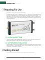
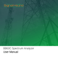
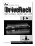
USB-TG124A Tracking Generator User Manual Signal Hound USB-TG124A User Manual 2015, Signal Hound, Inc. 35707 NE 86th Ave La Center, WA 98629 USA Phone 360.263.5006 • Fax 360.263.5007 ii Contents 1 Preparing For Use............................................................................................................................................................................ 1 1.1 Initial Inspection .................................................................................................................................................................................1 1.2 Software Installation .........................................................................................................................................................................1 2 Getting Started ................................................................................................................................................................................ 1 2.1 The USB-TG124A Front & Rear Panels ..........................................................................................................................................2 3 Taking Measurements .................................................................................................................................................................... 2 3.1 Measuring Insertion Loss or Gain ...................................................................................................................................................3 3.1.1 Improving Accuracy ....................................................................................................................................................................4 3.1.2 Testing High Gain Amplifiers ....................................................................................................................................................4 3.1.3 Measuring Insertion loss > 80 dB.............................................................................................................................................4 3.2 Measuring Return Loss.....................................................................................................................................................................4 3.2.1 Adjusting an Antenna .................................................................................................................................................................5 4 Theory of Operation ........................................................................................................................................................................ 5 5 Troubleshooting .............................................................................................................................................................................. 5 5.1.1 General Troubleshooting Procedure........................................................................................................................................5 5.1.2 General Advice to avoid problems ...........................................................................................................................................6 6 Calibration and Adjustment ........................................................................................................................................................... 6 7 Specifications .................................................................................................................................................................................. 6 7.1 Frequency ............................................................................................................................................................................................6 7.2 Amplitude ............................................................................................................................................................................................6 7.3 Spectral Purity ....................................................................................................................................................................................6 7.4 Inputs and Outputs ............................................................................................................................................................................6 7.5 Environment ........................................................................................................................................................................................7 7.6 Calibration ...........................................................................................................................................................................................7 7.7 Adjustments ........................................................................................................................................................................................7 8 Revision History............................................................................................................................................................................... 7 9 Warranty and Disclaimer ................................................................................................................................................................ 7 9.1.1 Warranty ........................................................................................................................................................................................7 9.1.2 Warranty Service .........................................................................................................................................................................8 9.1.3 Limitation of Warranty................................................................................................................................................................8 9.1.4 Exclusive Remedies ....................................................................................................................................................................8 iii 9.1.5 Certification ..................................................................................................................................................................................8 9.1.6 Credit Notice .................................................................................................................................................................................8 iv Preparing For Use | Initial Inspection 1 Preparing For Use Unpacking your Tracking Generator and Installing Software The Signal Hound USB-TG124A is a USB-based 100 kHz to 12.4 GHz economy tracking generator that works with the USB-SA44B and USB-SA124A, facilitating scalar network analyzer measurements. The Signal Hound USB-TG124A is powered from the USB cable, eliminating the need for a separate power supply. Measuring less than 8 inches long and weighing less than a pound, the Signal Hound can be used virtually anywhere! 1.1 INITIAL INSPECTION Check your package for shipping damage before opening. Your box should contain a USB cable, a CDROM, an SMA M-M adapter, a 3' BNC cable, and a Signal Hound USB-TG124A. 1.2 SOFTWARE INSTALLATION The USB-TG124A uses the same Spike software as your Signal Hound spectrum analyzer. No additional software installation is required. Additionally, there is a small standalone utility for using your USBTG124A without a USB-SA44B or USB-SA124B. 2 Getting Started Learn about the basic functions and features of your Signal Hound Tracking Generator 1 Taking Measurements | The USB-TG124A Front & Rear Panels The primary use for the USB-TG124A tracking generator is to form a scalar network analyzer when paired with the USB-SA124B spectrum analyzer and the Spike software. The insertion loss of filters, amplifiers, cables, and attenuators can be measured quickly and accurately from 100 kHz to 12.4 GHz. By adding a directional coupler, return loss can be measured as well. The Spike software is set up to sweep active devices, such as amplifiers, and passive devices, such as filters and attenuators. By default, high dynamic range is selected, which typically offers 90 dB of dynamic range (0 to -90 dB for passive devices, +20 to -70 dB for active devices, or +40 to -50 dB for active devices with a 20 dB fixed attenuator). High dynamic range sweeps take about ½ second for a 100 point sweep (span > 100 kHz). For crystals or other very high Q circuits, a second operating mode is available. This narrow-band mode is selected automatically when your span is 100 kHz or less. In this mode, a 100 point sweep takes about 7 seconds, but the sweep updates at each point. 2.1 THE USB-TG124A FRONT & REAR PANELS The front panel includes a 50Ω SMA RF input. There is a DC blocking capacitor that will block up to 16 VDC. Applying higher DC voltages or signals in excess of +20 dBm will cause damage. A READY / BUSY LED flashes orange each time a command from the computer is processed. The rear panel has three connectors: 1. 10 MHz Reference input / output. Used in the legacy software in some modes. 2. A USB type B connector. Connect to your PC using the included USB cable. 3. TG Sync. Connect to the USB-SA124B Sync Out port for spans of greater than 100 kHz. 3 Taking Measurements Learn how to take path loss, amplifier gain, and mixer gain/loss measurements 2 Taking Measurements | Measuring Insertion Loss or Gain The Signal Hound USB-TG124A Tracking Generator (TG), combined with the USB-SA124B Spectrum Analyzer (SA) and Spike software, is capable of making a wide range of scalar network analysis measurements. Whether you are tuning an RF filter, sweeping an amplifier to plot gain, or verifying a step attenuator, measurements are quick and easy with the USB-TG124A tracking generator. 3.1 MEASURING INSERTION LOSS OR GAIN The Signal Hound USB-TG124A Tracking Generator may be used to measure insertion loss or gain. To measure insertion loss of a cable or attenuator, the following approach is recommended: 1. Plug the spectrum analyzer and tracking generator devices into the PC using the supplied USB cables. 2. Connect the spectrum analyzer and tracking generator nose-to-nose using the SMA barrel connector provided. 3. Connect the TG Sync to the spectrum analyzer Sync Out. 4. Launch the Spike software. 5. Set start / stop / center / span frequencies to desired sweep range 6. Set your reference level to +10 dBm. This will place the “zero” insertion loss line one division from the top of the graticule. 7. Select Analysis Mode > Scalar Network Analyzer 8. Select your ideal sweep size. This will help the software determine step size (the frequency step between measurements). 9. If your device is passive (e.g. attenuator, filter, or cable), select Passive Device. For amplifiers with gain of up to 20 dB, select Active Device and change your reference level to +20 dBm. 10. If you wish to double the sweep speed and cut the dynamic range in half, Range. un-check High 11. With the spectrum analyzer and tracking generator still connected nose-to-nose, wait for a complete sweep to finish. Then click Store Thru. This will correct for the amplitude offsets between the TG and SA, and give you a stable line at 0 dB insertion loss. Note: If you change any settings after Store Thru, repeat this step. 12. (Optional) For maximum accuracy below -45 dB, insert a fixed attenuation of 20 to 30 dB, and then click Store 20 dB Pad. The actual attenuation used can be anywhere from 20 to 30 dB, and will be factored out automatically. This corrects for small offsets between the higher range 3 Taking Measurements | Measuring Return Loss and lower range readings. This is only used for settings of High Range, Passive Device. If you omit this step, accuracy below -40 dB should be treated as +/- 1 dB typical. 13. Insert the device to test and take measurements. 3.1.1 Improving Accuracy One shortcoming of the Signal Hound Spectrum Analyzer and Tracking Generator is poor VSWR / return loss performance. However, this can be easily overcome by adding good 3 dB or 6 dB pads (fixed SMA attenuators) to the output of the tracking generator and / or the input of the spectrum analyzer. A good 6 dB pad will improve return loss by nominally 12 dB to >20 dB, and should enable accurate measurements relative to a 50 ohm system. These may be included when sweeping the "thru," effectively nulling them out. This will decrease your overall dynamic range. 3.1.2 Testing High Gain Amplifiers When measuring an amplifier that will have gain of 20 to 40 dB, the use of a 20 dB pad is required. Simply insert the 20 dB pad before you Store Thru, and leave the pad on either the SA or TG when connecting to the amplifier. For amplifiers with Psat>+20 dBm, the pad should go on the output of the amplifier. If an amplifier cannot safely handle -5 dBm, place the pad on the amplifier’s input. 3.1.3 Measuring Insertion loss > 80 dB To measure more than 80-90 dB insertion loss, you will need to use Utilities > Tracking Generator Control. Set your frequency to the desired test frequency, and set the amplitude to -10 dBm. Find the CW signal using the USB-SA124B at about a 100 kHz span. Decrease your span down to about 10 kHz, keeping the signal centered, then reduce your RBW to 10 Hz or 100 Hz, depending on the dynamic range required. With a 10 Hz RBW, your noise floor will generally show about 140 dB of insertion loss. This method is especially good for tuning notch filters where your ultimate rejection at a specified frequency may need to be 100 dB or greater 3.2 MEASURING RETURN LOSS A directional coupler of appropriate frequency range (sold separately) may be used to make approximate return loss measurements. Connect your tracking generator to the "OUT" port, and connect your spectrum analyzer to the "COUPLED" port. Use the "IN" port as your S-parameter test port. Sweep this setup as the "thru" with the test port open (reflecting 100% of power). Then connect your device to test (e.g. antenna) to the "IN" port. Return loss or |S11| will be displayed. Once again, measurement accuracy will benefit from 3 to 6 dB pads on the Signal Hound devices. This method is not as accurate as using a precision vector network analyzer with a full two port calibration, but with a good directional coupler, measurements from 0 to -20 dB should be accurate. 4 Theory of Operation | Measuring Return Loss 3.2.1 Adjusting an Antenna To adjust an antenna for a certain frequency, it is often sufficient to simply maximize return loss at that frequency. This may be done in a swept or CW tracking generator mode. Mount your antenna and ground as you normally would, then connect to the "IN" port as above. Lengthen, shorten, and tweak impedance matching elements until the desired return loss is achieved. Be aware that you will be radiating some RF during this process. It is your responsibility to understand and obey laws regarding transmitting on those frequencies. 4 Theory of Operation Learn about the internal blocks that make up the Signal Hound Tracking Generator The Signal Hound Tracking Generator is built around a 32-bit programmable modulus DDS. This allows the firmware to set precise 10 Hz steps. The DDS generates frequencies from 10 Hz to 28 MHz directly. To produce higher frequencies, the DDS output frequency is multiplied by an integer from 5 to 500. Below 28 MHz, the output has low harmonic content. However, above 28 MHz, harmonics are generated and not filtered. From 4 GHz to 7.2 GHz, an Fout / 2 subharmonic will also be present, and above 7.2 GHz there will be Fout/3 and 2*Fout/3 subharmonics. Harmonics and / or subharmonics, sometimes as high as -10 dBc, will be observed. For use as a tracking generator, the presence of harmonics has very little impact on the measurement, since the harmonics will generally be well outside the spectrum analyzer's input bandwidth. However, when verifying the output power level with an RF power meter, the harmonic content can add typically up to 0.7 dB to the measured output. Please note that the phase noise of the USB-TG124A is higher than the USB-SA124A. However, this will have minimal impact on readings as out-of-band energy is rejected by the spectrum analyzer. 5 Troubleshooting 5.1.1 General Troubleshooting Procedure 1. Before troubleshooting the TG124A, make sure your USB-SA124B is working properly. 2. The most common cause of the TG124A not working is a missing or damaged BNC cable between the TG sync and the SA sync. If the LED on the TG124A is red during scalar network analyzer sweeps, this is likely the problem. 3. Unplug the USB cable from your Tracking Generator, count to 10, and plug it back in. If the LED is green, proceed. Otherwise, try a different USB port or cable. 5 Calibration and Adjustment | Frequency Otherwise, contact technical support at http://www.signalhound.com 5.1.2 General Advice to avoid problems Unplug your USB-TG124A from the USB port when not in use, or before shutting down your computer. 6 Calibration and Adjustment Contact Test Equipment Plus for more information regarding calibration software and required equipment. 7 Specifications 7.1 FREQUENCY Frequency range 100 kHz to 12.4 GHz Frequency Accuracy ±1ppm/year Frequency steps Below 4 GHz output, 19 selectable step sizes from 10 Hz to 10 MHz Above 4 GHz, 16 step sizes from 100 Hz to 10 MHz 7.2 AMPLITUDE Amplitude range -30 to -12 dBm. (-30 to -10 dBm typical) Absolute Amplitude accuracy ±2.0 dB Amplitude steps resolution 1 dB 7.3 SPECTRAL PURITY Harmonics Typically < -10dBc 7.4 INPUTS AND OUTPUTS BNC Timebase Input/Output (10 MHz output) BNC TG Sync SMA RF Output 6 Revision History | Environment 7.5 ENVIRONMENT 20° C to 25° C to achieve published specifications 0° C to 70° C safe operating range with derated amplitude specifications 7.6 CALIBRATION Test with factory calibration software to verify that USB-TG124A is operating within tolerance. Recommended calibration interval is 1 year at 20°C to 25°C. 7.7 ADJUSTMENTS Factory adjustment software shall be used to generate new calibration constants when USB-TG124A will not pass calibration. 8 Revision History Version 3.00 – Initial release under the Spike software 9 Warranty and Disclaimer ©2015 Test Equipment Plus. All rights reserved Reproduction, adaptation, or translation without prior written permission is prohibited, except as allowed under the copyright laws. 9.1.1 Warranty The information contained in this manual is subject to change without notice. Test Equipment Plus makes no warranty of any kind with regard to this material, including, but not limited to, the implied warranties or merchantability and fitness for a particular purpose. Test Equipment Plus shall not be liable for errors contained herein or for incidental or consequential damages in connection with the furnishing, performance, or use of this material. This Test Equipment Plus product has a warranty against defects in material and workmanship for a period of one year from date of shipment. During the warranty period, Test Equipment Plus will, at its option, either repair or replace products that prove to be defective. 7 Warranty and Disclaimer | Adjustments 9.1.2 Warranty Service For warranty service or repair, this product must be returned to Test Equipment Plus. The Buyer shall pay shipping charges to Test Equipment Plus and Test Equipment Plus shall pay UPS Ground, or equivalent, shipping charges to return the product to the Buyer. However, the Buyer shall pay all shipping charges, duties, and taxes, to and from Test Equipment Plus, for products returned from another country. 9.1.3 Limitation of Warranty The foregoing warranty shall not apply to defects resulting from improper use by the Buyer, Buyersupplied software or interfacing, unauthorized modification or misuse, operation outside of the environmental specifications for the product. No other warranty is expressed or implied. Test Equipment Plus specifically disclaims the implied warranties or merchantability and fitness for a particular purpose. 9.1.4 Exclusive Remedies The remedies provided herein are the Buyer’s sole and exclusive remedies. Test Equipment Plus shall not be liable for any direct, indirect, special, incidental, or consequential damages, whether based on contract, tort, or any other legal theory. 9.1.5 Certification Test Equipment Plus certifies that, at the time of shipment, this product conformed to its published specifications. 9.1.6 Credit Notice Windows is a registered trademark of Microsoft Corporation in the United States and other countries. 8