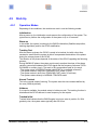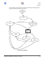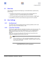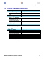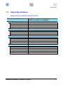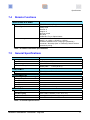
1
OSA 5210
Telecom GNSS
CLOCK
USER MANUAL
Model 945.521.000.03
Model 945.521.000.04
Model 945.521.000.10
OSA 5210 - User Manual - Revision B - July 2012
This page has been intentionally left blank
OSA 5210 - User Manual - Revision B - July 2012
ii
What's new in this revision
v Add drawing for Sub-D/BNC output connector model
v Add pin-out for NTP connector
v Update drawings
OSA 5210 - User Manual - Revision B - July 2012
iii
This page has been intentionally left blank
OSA 5210 - User Manual - Revision B - July 2012
iv
Contents
Table of Contents
1
2
3
4
5
6
INTRODUCTION .................................................................................................................1-1
1.1
About this Manual ..................................................................................................1-3
1.2
Reading Guide ........................................................................................................1-4
1.3
Safety Instructions .................................................................................................1-5
1.4
Warranty..................................................................................................................1-8
1.5
Certification ............................................................................................................1-9
GENERAL DESCRIPTION ................................................................................................ 2-11
2.1
Overview ...............................................................................................................2-13
2.2
Functions .............................................................................................................. 2-13
EQUIPMENT DESCRIPTION ..............................................................................................3-1
3.1
Block Diagram ........................................................................................................3-3
3.2
Input Selection........................................................................................................3-3
3.3
Front Panel Layout .................................................................................................3-4
INSTALLATION ..................................................................................................................4-1
4.1
Unpacking and Inspection .....................................................................................4-3
4.2
Working Conditions ...............................................................................................4-3
4.3
Power Supplies.......................................................................................................4-4
4.4
Antenna and Auxiliary Input Connections ............................................................ 4-6
4.5
Output Connections ...............................................................................................4-8
4.6
Alarm Output Connection .................................................................................... 4-11
4.7
RS-232 Connector ................................................................................................ 4-12
4.8
TCP-IP Connector ................................................................................................. 4-12
4.9
Start-Up .................................................................................................................4-13
4.10
Setting-up IP Settings after Power-up (TL1) ....................................................... 4-16
4.11
Download .............................................................................................................. 4-18
CONFIGURING THE UNIT ..................................................................................................5-1
5.1
Overview .................................................................................................................5-3
5.2
User Settings ..........................................................................................................5-3
5.3
Default Factory Settings ........................................................................................5-6
REMOTE & LOCAL MANAGEMENT ..................................................................................6-1
6.1
TL1 Command List ................................................................................................. 6-3
OSA 5210 - User Manual - Revision B - July 2012
v
Contents
7
8
6.2
SNMP Overview .................................................................................................... 6-20
6.3
Software Information MIB .................................................................................... 6-21
6.4
SNMP Management Console ............................................................................... 6-22
SPECIFICATIONS ...............................................................................................................7-1
7.1
Input Specifications ...............................................................................................7-3
7.2
Tracking Subsystem Characteristics .................................................................... 7-4
7.3
Output Specifications ............................................................................................7-5
7.4
Remote Functions ..................................................................................................7-7
7.5
General Specifications ...........................................................................................7-7
MAINTENANCE ..................................................................................................................8-1
8.1
Overview .................................................................................................................8-3
8.2
Oscilloquartz Contact Information ........................................................................ 8-3
ORDERING INFORMATION............................................................................................................. I
GLOSSARY.................................................................................................................................... III
DOCUMENT HISTORY .................................................................................................................. V
OSA 5210 - User Manual - Revision B - July 2012
vi
List of Figures
List of Figures
Figure 3-1 Block Diagram ............................................................................................................ 3-3
Figure 3-2 Front Panel Layout...................................................................................................... 3-4
Figure 4-1 Power Supply Connection ........................................................................................... 4-5
Figure 4-2 Input Connections ....................................................................................................... 4-6
Figure 4-3 TEX-P Connection to OSA 5210 GPS + GLONASS Receiver..................................... 4-7
Figure 4-4 Output Connection ...................................................................................................... 4-8
Figure 4-5 TOD Pin-out ................................................................................................................ 4-9
Figure 4-5 Alarm Output Connection .......................................................................................... 4-11
Figure 4-7 State Diagram ........................................................................................................... 4-14
Figure 4-8 : Firmware Download Overview ................................................................................ 4-18
Figure 6-1 : SyncTerminal (example) ........................................................................................... 6-4
Figure 6-2 : SyncTerminal Short Cut Menu .................................................................................. 6-7
Figure 6-3 : SyncTerminal Main or Command Menu .................................................................... 6-8
Figure 6-4 SNMP MIB example.................................................................................................. 6-21
OSA 5210 - User Manual - Revision B - July 2012
vii
List of Tables
List of Tables
Table 3-1 Connector Description.................................................................................................. 3-4
Table 4-2 Sub-D9 Pin-out ............................................................................................................ 4-8
Table 4-1 TOD Pin-out ................................................................................................................. 4-9
Table 4-2 RS 232 Pin-out........................................................................................................... 4-12
Table 4-3 TCP-IP Pin-out ........................................................................................................... 4-12
Table 4-4 Not retrievable with TL1 commands for evident security reason. ................................ 4-20
Table 4-5 Led information .......................................................................................................... 4-22
Table 5-1 Default Factory Settings ............................................................................................... 5-6
Table 6-1 Keyboard Shortcuts for Typing TL1 Commands ......................................................... 6-17
Table 7-1 Input Specifications ...................................................................................................... 7-3
Table 7-2 Tracking Sub-System Characteristics........................................................................... 7-4
Table 7-3 Output Specifications ................................................................................................... 7-6
Table 7-4 Remote Functions Specifications ................................................................................. 7-7
Table 7-5 General Specifications ................................................................................................. 7-7
Table 8-1 Ordering Units .................................................................................................................. I
Table 8-2 Ordering Miscellaneous Accessories ............................................................................... I
OSA 5210 - User Manual - Revision B - July 2012
viii
List of Procedures
List of Procedures
Procedure 4-1 Power-Up ............................................................................................................. 4-4
Procedure 6-1 SyncTerminal Communication Configuration and Set-up .................................... 6-13
Procedure 6-2 Typing TL1 Commands ...................................................................................... 6-16
Procedure 6-3 SNMP Management Config. ............................................................................... 6-25
Procedure 6-4 SNMP Trap Verification. ..................................................................................... 6-27
OSA 5210 - User Manual - Revision B - July 2012
ix
List of Procedures
This page has been intentionally left blank
OSA 5210 - User Manual - Revision B - July 2012
x
Introduction
Chapter
1 Introduction
Including :
v About this Manual
v Reading Guide
v Safety
v Warranty
v Certification
OSA 5210 - User Manual - Revision B - July 2012
1-1
Introduction
This page has been intentionally left blank
OSA 5210 - User Manual - Revision B - July 2012
1-2
Introduction
1.1
About this Manual
This manual has been designed to provide basic and detailed information for the correct
use and operation of the OSA 5210 Telecom GNSS Clock. It summarizes the overall
equipment concept and theory of operation, describes the hardware itself and provides
information related to installation, operation and maintenance.
It is intended for the use of the following types of users:
1.1.1
Systems Engineers:
An overview of the equipment concept and theory of
operation.
Installation Engineers:
Detailed technical information and procedures for
correct installation, operation, configuration and
commissioning as well as equipment specifications
and maintenance guidelines.
Maintenance Engineers:
Information on troubleshooting, maintenance and
equipment technical data.
Copyright Notice
Copyright © 2012 Oscilloquartz SA
All Rights Reserved
The Oscilloquartz product described in this book is furnished under a license
agreement and may be used only in accordance with the terms of the agreement.
The contents and information in this document are provided in connection with
Oscilloquartz products. No license, expressed or implied by estoppels or otherwise, to
any intellectual property rights is granted by this document. Except as provided in
Oscilloquartz SA’s Terms and Conditions of Sale for such products.
This document is exclusive property of Oscilloquartz SA and may not, in whole or in
part, be copied, photocopied, reproduced, modified, translated, reduced to any
electronic medium or machine-readable, stored in a retrieval system, or transmitted in
any form without prior consent in writing from Oscilloquartz SA, Brévards 16, 2002
Neuchâtel 2, Switzerland.
Every effort has been made to ensure the accuracy of this guide. However,
Oscilloquartz SA makes no warranties with respect to this documentation and
disclaims any implied warranties of merchantability and fitness for a particular
purpose. Oscilloquartz SA shall not be liable for any errors or for incidental or
consequential damages in connection with the furnishing, performance, or use of this
manual or the examples herein.
Oscilloquartz SA may make changes to specifications and product descriptions at any
time, without notice.
OSA 5210 - User Manual - Revision B - July 2012
1-3
Introduction
1.2
Reading Guide
Special icons, attracting your attention, precede important and/or critical information in this
document. Hereafter are explanations of each icon.
CAUTION
This symbol is extremely important and must not be neglected. It precedes
information or procedures regarding installation, operation or maintenance.
Follow all steps or procedures, as instructed, to avoid any damage to
equipment or serious personal injury.
ELECTRICAL SHOCK HARZARD
This warning symbol is extremely important and must not be neglected. It
indicates that there are dangerous high voltages present inside the
enclosure of this product and precedes important warnings to avoid any risk
of fire or electrical shock that could lead to serious personal injury or loss of
life.
ESD CAUTION
Electrostatic Discharge (ESD) must be avoided so as not to damage or
destroy static sensitive components.
Note:
A note symbol informs the reader that additional information on the related
subject is provided in order to simplify a described task, suggest other
references or even just simplify an explanation.
Recommendation:
Recommendations advise the user on manufacturer tested methods and
procedures proven valuable for correct use and optimum equipment results.
OSA 5210 - User Manual - Revision B - July 2012
1-4
Introduction
1.3
Safety Instructions
IMPORTANT SAFETY INSTRUCTIONS.
DO NOT DISCARD, READ BEFORE OPERATING
GENERAL
Exercise extreme care when handling any electronics equipment as it
contains precision parts that can be damaged by improper handling.
Avoid touching connector pin surfaces. Foreign matter deposited on contact
surfaces can cause corrosion, and eventually lead to degradation of
performance. In addition, do not use abrasives to clean contact/pin surfaces.
ESD CONSIDERATION
Each module contains semiconductor devices that can be damaged by
electrostatic discharges. It is advisable to take anti-static precautions when
handling electronic boards or static sensitive components. Use an approved
anti-static bracelet in accordance with company practice.
WATER AND MOISTURE
Do not place containers with liquids such as coffee, water, sodas, etc. on
this unit. Do not operate this equipment in a wet environment.
HEATING
Do not install this product near heat sources such as radiators, air ducts,
areas subject to direct, intense sunlight, or other products that produce heat.
OSA 5210 - User Manual - Revision B - July 2012
1-5
Introduction
VENTILATION
Slots and openings in the unit are provided for ventilation and to ensure
reliable operation of the product. To protect the unit from overheating, those
openings must not be blocked or covered.
GROUNDING
EARTH CONNECTION IS ESSENTIAL BEFORE CONNECTING TO THE
SUPPLY.
The OSA 5210 Telecom GNSS CLOCK must be connected to Earth Ground
(common bounding network (DC-C)). The wire used for the connection must
be a minimum of AWG16.
Ensure that all other devices connected to the 5210, are connected to
protective (earth ground). (Grounding one conductor of a two-conductor
outlet is not sufficient.)
Any interruption of the protective (grounding) conductor (inside the
equipment) or disconnecting the protective earth terminal is likely to make
this equipment dangerous. Intentional interruption is prohibited.
POWER
Make sure the power sources are compatible with the power inputs of the
equipment. The equipment's protective earth terminals must be connected to
the protective conductor of the (mains) power cord or the station earth. The
mains plug shall only be inserted in a socket outlet provided with a protective
earth contact. The protective action must not be negated by the use of an
extension cord (power cable) without a protective conductor (grounding).
OSA 5210 - User Manual - Revision B - July 2012
1-6
Introduction
POWER CORD PROTECTION
The power supply cord for this product should be routed or installed in such
a manner to protect it from being walked on or pinched. The unit should be
powered down completely before connecting or disconnecting the power
cable. The power cord should be removed before moving the unit. The
power cord must be placed near an easily accessible unobstructed socket
outlet.
CLEANING
Connected and running equipment can only be dusted using a soft dry cloth.
ONLY WITH, AUTHORIZED PERMISSION, OUT OF SERVICE &
UNPLUGGED equipment can be cleaned with a soft cloth slightly moistened
with a mild detergent solution. Do not use liquid cleaners, aerosols, abrasive
pads, scouring powders or solvents, such as benzine or alcohol. Ensure the
surface cleaned is fully dry before reconnecting power.
SERVICING AND MODIFICATIONS
To avoid dangerous electric shock, do not perform any servicing or
modifications other than what is recommended in this User Manual. Do not
attempt to gain access to areas of the unit where dangerous voltages are
present. Refer servicing to qualified service personnel.
DAMAGE REQUIRING SERVICE
·
Refer servicing to qualified service personnel under the following
conditions:
· When the power supply cord is damaged.
· If liquid has been spilled into the enclosure of the unit.
· If the product does not function normally by following the instructions
in the User’s Manual. Adjust only those controls that are covered by
the operating instructions. Improper adjustment of other controls may
result in damage and will often require rework by a qualified
technician to restore the product to its normal operation.
· If the product has been damaged in any way.
When the unit displays a negative, distinct change in performance.
OSA 5210 - User Manual - Revision B - July 2012
1-7
Introduction
1.4
Warranty
This Oscilloquartz product carries a warranty which commences from date of dispatch
from factory. Unless agreed otherwise or stipulated differently on the original
acknowledgement of order, the duration of the warranty is twenty four months.
It applies to demonstrably faulty material or poor workmanship, but excludes batteries.
Oscilloquartz shall bear only the cost of repair or replacement in its own premises. Should
this not be possible for reasons beyond our control, all additional costs are at customer
expense.
Repairs under warranty carry either the balance of the original warranty or a six months
warranty, whichever is longer.
Damages resulting from natural wear, improper maintenance, failure to observe the
operating instructions, excessive strain, unsuited consumption material as well as
improper environmental and mounting conditions are excluded from this warranty.
The warranty expires if the customer or a third party modifies or repairs the product
without Oscilloquartz's prior written consent or if the customer does not take immediate
steps to prevent the damage from becoming more serious; likewise, if insufficient time is
provided for repair or replacement.
The customer will not be entitled to other warranty claims. Oscilloquartz is not liable for
consequential damage.
OSA 5210 - User Manual - Revision B - July 2012
1-8
Introduction
1.5
Certification
EQUIPMENT CERTIFICATION:
Oscilloquartz equipment is tested according to well-defined procedures. Appropriate
testing and inspection takes place at the component, board, equipment and system levels.
The company maintains in-house cesium standards that are continuously compared to
UTC. Before any equipment is released, it must satisfy the relevant tests and inspection
schedules. The equipment is then issued with a "Certificate of Conformity" that
guarantees its conformance with the relevant performance criteria.
The OSA 5210 is designed to be compliant to:
In progress
A variety of Oscilloquartz products are certified world-wide. For details, please refer to our
web site at www.oscilloquartz.com
COMPANY CERTIFICATION:
Certified since 1987 by the Swiss Accreditation Service as an accredited laboratory for
time and frequency.
Certified ISO 9001 since 1994 and ISO 14001 since 2000 by The Swiss Association for
Quality and Management Systems (SQS).
OSA 5210 - User Manual - Revision B - July 2012
1-9
Introduction
This page has been intentionally left blank
OSA 5210 - User Manual - Revision B - July 2012
1-10
General Description
Chapter
2 General Description
Including :
v Overview
v Functions
OSA 5210 - User Manual - Revision B - July 2012
2-11
General Description
This page has been intentionally left blank
OSA 5210 - User Manual - Revision B - July 2012
2-12
General Description
2.1
Overview
The OSA 5210 Telecom GNSS CLOCK provides an accurate
frequency derived from the Global Navigation Satellite System
(GLONASS) and/or Global Positioning System (GPS) satellites. In
addition, the OSA 5210 Telecom GNSS CLOCK module is equipped
with an auxiliary input, which accepts either frequency (2.048MHz/5MHz/10MHz) or E1
code. Depending of the configuration of the module, the GNSS or the auxiliary input can
be used as the reference for the tracking function.
When locked, the ‘5210' regenerates the selected reference and attenuates jitter and
wander on this reference. When no valid input reference is available, the 'GPS 5210
enters hold-over mode and holds its output frequency to the one that was available just
before the loss of the input.
2.2
Functions
The OSA 5210 Telecom GNSS CLOCK is an Oscilloquartz CLOCK with holdover
capability together with G.703 auxiliary input. When locked to GNSS, the OSA 5210 fulfils
the ITU-T rec. G.811. The OSA 5210 GNSS performs the following:
·
Supplies ITU-T G.811 references with valid GNSS signal
·
Redundant power supply
·
TL1 commands with SyncTerminal and easy graphical pull down menus
·
Can include an SNMP agent that allows the unit to be managed by any SNMPcompliant management software.
·
Provides 2 asymmetrical outputs groups on BNC with 4 outputs configurable,
PPS/E1/FREQ or 10MHz/E1/FREQ. (optional symmetrical Sub-D group only for
model 945.521.000.10)
·
Provide Time Of Day output or NTP output (option)
·
Monitors the status of the reference input signals (GNSS and auxiliary
synchronization signal)
·
Selects the highest priority (operator specified) synchronization input
·
Selects the next available synchronization input in the priority table, if the current
synchronization input has failed
·
Automatic switching without phase jump
OSA 5210 - User Manual - Revision B - July 2012
2-13
General Description
·
Attenuates jitter and wander on the selected synchronization input
·
Operates as a standby reference clock in hold-over mode if all synchronization
inputs have decreased in quality or failed
In addition, the OSA 5210 GPS + GLONASS Receiver also features:
·
Totally maintenance-free design.
OSA 5210 - User Manual - Revision B - July 2012
2-14
Equipment Description
Chapter
3 Equipment Description
Including :
v Block Diagram
v Input Selection
v Front Panel Layout
OSA 5210 - User Manual - Revision B - July 2012
3-1
Equipment Description
This page has been intentionally left blank
OSA 5210 - User Manual - Revision B - July 2012
3-2
Equipment Description
3.1
Block Diagram
OSA 5210 GPS + GLONASS
Block Diagram
Antenna
GNSS ENGINE
Tracking System
Remote
Management
Interface
RS232C
TOD or
NTP output (option)
Internal communication
PPS / FREQ / E1
Auxiliary input
OCXO 8663
Micro Controller
LED indicator
Alarm contacts
Frequency &
Time Code
Output
Outputs factory configurables
PPS/10MHz/E1/FREQ
Figure 3-1 Block Diagram
3.2
Input Selection
The user has the possibility to configure the input selection process of the OSA 5210
Telecom GNSS CLOCK by choosing from a table listing the priority of each input. For
example : Selecting the GLONASS/GPS signal to have higher priority than the auxiliary
synchronization input.
Input selection is reversible. 1
1
Reversible: If a valid input with higher priority than the current reference returns, the equipment
will select the higher priority input as its primary reference input.
3-3
OSA 5210 - User Manual - Revision B - July 2012
Equipment Description
3.3
Front Panel Layout
3.3.1
Connectors
TOD
Aux inputs
LED (Unit Status)
Alarm Relay
Antenna
10 MHz/E1 /FREQ
outputs
1PPS /E1 /FREQ
outputs
RS 232
TCP-IP
SUPPLY 1 & 2
Figure 3-2 Front Panel Layout
Connector Name
Type
Description
ANTENNA INPUT
BNC jack
GPS Antenna Input
AUX IN
BNC jack
AUX In, 2.048MHz, 5MHz, 10MHz Sine
Wave, 1PPS, E1
OUT 1 to 4
BNC jack
E1 or 2.048MHz or 10MHz Sine Wave
OUT 5 to 8
BNC jack
E1 or 2.048MHz Sine Wave or 1 PPS
RS232
Sub-D9 male
RS 232 communication
TOD/NTP
RJ45
Time of Day or Network Time Protocol
REMOTE MGMT
RJ45
TCP/IP Ethernet network (SNMP and TL1)
ALARM
Weidmüller 5.08 / 3 poles
Electrical Alarm Output
20-60V
Weidmüller 5.08 / 3 poles
Redundant supply voltage Input (floating)
FUSE
Fuse T 3.15A L 250V
Signal Ground
Table 3-1 Connector Description
OSA 5210 - User Manual - Revision B - July 2012
3-4
Equipment Description
Optional connections for model 945.521.000.10 only
E1/FREQ
symmetrical outputs
Connector Name
10MHz
output
1PPS
output
Type
TCC-NTP
Description
OUT 1 to 8
Subd-9 female
2.048MHz, E1
10MHz
BNC female
10MHz Sine Wave
PPS
BNC female
1 PPS
TOD/NTP
RJ45
Time of Day or Network Time Protocol
OSA 5210 - User Manual - Revision B - July 2012
3-5
Equipment Description
This page has been intentionally left blank
OSA 5210 - User Manual - Revision B - July 2012
3-6
Installation
Chapter
4 Installation
Including :
v Unpacking and Inspection
v Working Conditions
v Power Supplies
v Antenna and Auxiliary Input Connections
v Output Connection
v Alarm Output Connection
v RS-232 Connector
v TCP-IP
v Start-Up
v Setting-up IP Settings after Power-up (TL1)
v Download
OSA 5210 - User Manual - Revision B - July 2012
4-1
Installation
This page has been intentionally left blank
OSA 5210 - User Manual - Revision B - July 2012
4-2
Installation
This section provides unpacking and Inspection instructions, working conditions, tools
required and power up for the OSA 5210 Telecom GNSS CLOCK. To prevent injury
and/or equipped damage, do not ignore the warnings, notes and recommendations and
read the section Safety Considerations
Note:
If you encounter problems during any of the following procedures, please
contact Customer Services.
4.1
Unpacking and Inspection
ESD CAUTION
Electrostatic Discharge (ESD) must be avoided so as not to damage or
destroy static sensitive components in the OSA 5210 Telecom GNSS
CLOCK. Please observe proper ESD handling procedures.
Check first that the packing does not have any signs of rough handling such as dents or
scratches, which might have occurred during transportation. Also inspect the equipment
carefully for possible damages (knobs broken, handles bent, etc.).
Should the equipment have suffered any damage, immediately notify the carrier and retain
the packing material for inspection.
CAUTION
This instrument must be operated only as specified by the manufacturer.
Use other than as specified may compromise the safety precautions of the
system.
4.2
Working Conditions
In order to work within specification, the OSA 5210 Telecom GNSS CLOCK should be
installed at a location which does not exceed the following working conditions:
Operating temperature range :
Humidity
:
-5°C to +55°C
Up to 95% non condensing
OSA 5210 - User Manual - Revision B - July 2012
4-3
Installation
4.3
Power Supplies
CAUTION
Check that the type of supply voltage corresponds to your power feed.
4.3.1
Power-Up
In order to ensure correct powering-up of the system, it is necessary to follow these
instructions:
STEP
ACTION
1
Connect the ground cable to the Signal Ground Stud if you wish to link
the signal ground of the OSA 5210 Telecom GNSS CLOCK to earth. The
ground stud is an M3 screw. Connection must be made with a suitable
connector.
2
Measure voltage and polarity of the external power source before
connecting it to the power input of the OSA 5210 Telecom GNSS
CLOCK. The voltage must be within the specified range.
3
Allow for the GPS to warm up, so that the internal oscillator can reach its
operating temperature. The minimum warm-up time is 10 minutes (24
hours before full specification are obtained).
4
Power Consumption : >15 W @ +25°C (steady state).
Procedure 4-1 Power-Up
OSA 5210 - User Manual - Revision B - July 2012
4-4
Installation
Figure 4-1 Power Supply Connection
OSA 5210 - User Manual - Revision B - July 2012
4-5
Installation
4.4
Antenna and Auxiliary Input Connections
Antenna Input
Aux Input
Figure 4-2 Input Connections
4.4.1
Auxiliary Input Connection
Recommendation:
Check that the incoming reference signals match the Auxiliary Input
type (shape, level, frequency, impedance).
Connect the input line to the Auxiliary Input connector according to the wiring plan. In
the case where an input reference signal must be derived from a
G.703-9 traffic carrying signal, insert an OSA TEX-P Passive Timing Extractor (part
no. 942.089.035) and connect it to the OSA 5210 Telecom GNSS CLOCK as
described below.
Note:
For balanced input type (G703-13 & G703-9), an adapter (120->75W)
should be use. Please refer to miscellaneous accessories chapter.
OSA 5210 - User Manual - Revision B - July 2012
4-6
Installation
4.4.1.1
Timing Extractor – Passive (TEX-P)
Signal from unterminated E1 link can be connected to the OSA 5210 GPS +
GLONASS using an external TEX-P. The TEX-P is a passive in-line device normally
mounted externally to the equipment. It is used to couple the E1 link to the
equipment. The device works as a sort of a "sniffer" which taps off a portion of the
digital signal without interfering with traffic or degrading the link in any way. The TEXP handles up to two separate E1 feeds.
OSA TEX-P
2.048Mbit/s feed
with traffic
Switch
Auxiliary
Input
OSA 5210
GPS +
GLONASS
Figure 4-3 TEX-P Connection to OSA 5210 GPS + GLONASS Receiver
OSA 5210 - User Manual - Revision B - July 2012
4-7
Installation
4.5
Output Connections
These need to be connected in accordance with the user’s network plan and/or wiring
schedules. Outputs are selected at factory.
4.5.1
BNC Models
10MHz/2.048MHz/E1
2.048MHz/1PPS/E1
Figure 4-4 Output Connection
Recommendation:
Check that the required output signals are compatible with the outputs
available on the OSA 5210 (shape, level, frequency, impedance).
Connect the outputs to the equipment that needs synchronization in accordance with
the user’s network plan and/or wiring schedules
4.5.2
Sub-D/BNC Models
5
9
1
6
Female
Pin No.
1
2
8
9
4,5,6
3, 7
Description
OUT 1b, OUT 3b, OUT 5b, OUT 7b
OUT 1a, OUT 3a, OUT 5a, OUT 7a
OUT 2b, OUT 4b, OUT 6b, OUT 8b
OUT 2a, OUT 4a, OUT 6a, OUT 8a
Ground
no connection
Table 4-1 Sub-D9 Pin-out
OSA 5210 - User Manual - Revision B - July 2012
4-8
Installation
4.5.3
Time of Day Connector (TOD)
This connector provides a TOD/NTP signal, depending on the option ordered.
Baud-rate:
Data bits:
Stop bits:
Parity:
Handshake:
4800
8
1
None
None
The format for sending commands is ASCII, terminating by ;<CR><LF>.
The format of the receiving commands is ASCII, terminating by ;<CR><LF> at the
end of each line.
The space characters are ignored in a command. A command with capital or tiny
letter is the same effect.
The NMEA spontaneous TOD information begin with a “$”, followed by the
command’s name.
Each parameter is separated with a “,”.
The command is terminated by a “*” followed by the checksum.
Finally, the string is terminated by “CR and LF”
Example TOD:
$GPZDA,104534,11,07,2001,+00,00*CS<cr><lf>
1 2 3 4 5 6 7 8
Pin No.
5
6
4
1,2,3,7,8
Description
Rx
Tx
Ground
NC
Table 4-2 TOD Pin-out
Figure 4-5 TOD Pin-out
OSA 5210 - User Manual - Revision B - July 2012
4-9
Installation
Note:
During warm-up and almanacs satellites acquisition phase, the system
isn’t able to send TOD information: TOD_NOT_VALID;<cr><lf>
1 2 3 4 5 6 7 8
Pin No.
1
2
3
6
4, 5,7,8
Description
Tx+ (Transmit data+)
Tx- (Transmit data-)
Rx+ (Receiver data+)
Rx- (Receiver data-)
NC
Table 4-3 NTP Pin-out
Figure 4-6 NTP Pin-out
OSA 5210 - User Manual - Revision B - July 2012
4-10
Installation
4.6
Alarm Output Connection
This electrical alarm is issued from relay isolated contacts and is available on the ‘ALARM’
connector.
Absolute maximum ratings
U = 150VDC or 125VAC
I = 1A
The alarm output works in “Normally Closed” or “Normally Opened” mode (depending of
the wiring). In “Normally Closed” mode, the relay contacts are open when there is an
alarm condition or when the OSA 5210 GNSS is switched-off while it is closed in
“Normally opened” mode.
“Normally Closed” wiring
“Normally Opened” wiring
Figure 4-7 Alarm Output Connection
OSA 5210 - User Manual - Revision B - July 2012
4-11
Installation
4.7
RS-232 Connector
Local management via Terminal software.
1
6
Pin No.
2
3
5
1, 4 6, 7, 8 ,9
5
9
male
Description
Rx mgmt
Tx mgmt
Ground
no connection
Table 4-4 RS 232 Pin-out
Note:
To manage or visualize MGMT PORT (RS232) use a null modem cable.
4.8
TCP-IP Connector
Remote management via Element Manager software or SyncView Plus Server Network.
1 2 3 4 5 6 7 8
Pin No.
1
2
3
6
4, 5,7,8
Description
Tx+ (Transmit data+)
Tx- (Transmit data-)
Rx+ (Receiver data+)
Rx- (Receiver data-)
NC
Table 4-5 TCP-IP Pin-out
Figure 4-8 TCP-IP Pin-out
OSA 5210 - User Manual - Revision B - July 2012
4-12
Installation
4.9
4.9.1
Start-Up
Operation Modes
Depending of the conditions, the module can work in one the following modes:
Initialization
After a power-up, the initialization mode assures the configuration of the system. The
typical time to perform the configuration of the system is up to 10 seconds.
Warm-up
In this mode, the system is waiting for the GNSS initialization (Satellites acquisition,
tracking algorithms) and for the OCXO stabilization.
Tracking Fast
After the warm-up phase, the OCXO is ready to be tracked, but with a short time
constant to assure that the system is able to compensate the deviation of the phase
during the retrace phase of the OCXO.
The duration of this phase depends of the status of the OCXO regarding the following
process:
During WARM-UP phase, the system continuously monitors the slope of the phase
variation versus time between the OCXO signal and the frequency reference (GPS +
GLONASS or auxiliary input). The result of this computation leads to four ways:
- The system stays in WARM-UP mode (cold OCXO or unavailable reference)
- The system enters in long time TRACKING FAST mode (1 hour)
- The system enters in short time TRACKING FAST mode (10 minutes)
- The systems enters directly in NORMAL TRACKED mode.
Normal Tracked
This is the normal mode of working. The system uses the time constant defined by
the user (2000s by default)
Holdover
If no input is available, the module enters in holdover mode. The tracking function is
blocked and the OCXO delivers its own frequency for the outputs
Tracked Initial
Tracked initial indicate that the GNSS engine is trying to enter in position fix. With
good sky view, the system enters typically after 24 hours.
OSA 5210 - User Manual - Revision B - July 2012
4-13
Installation
The state diagram hereunder shows the different transitions that could be appear in
the OSA 5210 Telecom GNSS CLOCK module.
Power-Off
Power-On
Initialisation
t < 10s
Warm-up Time > 12 min
while none input avaible
Warm-Up
Holdover
(Heating of OCXO, Satellites
acquisition)
Input avaible
Check
Delta_f/f
None input avaible
Normal
Tracked
< 1.25e-9
600s elapsed
< 3.5e-9
< 8.6e-9
Short
Tracked Fast
3600s elapsed
Long
Tracked Fast
Figure 4-9 State Diagram
OSA 5210 - User Manual - Revision B - July 2012
4-14
Installation
4.9.2
Power-Up
A few seconds after power-up, the status of the system must be:
Green LED is blinking,
indicates that one or more unmasked alarm conditions are active on the module
(INIT/WARM-UP, GNSS, AUX, OCXO alarm conditions).
Þ If the red LED is blinking,
it indicates a connection problem between the module and the antenna
(antenna over-current or undercurrent ). Antenna alarm condition has to be
unmasked. This indication could appear only a few minutes after power-up
even if the antenna is incorrectly connected.
After approximately 12 minutes:
If both GPS/GLONASS and AUX references are unavailable (or disabled) :
Red LED is on,
means that the module is in HOLDOVER mode
If GNSS or AUX references are available :
Green LED is blinking,
means that the module is operating in TRACKING FAST mode. Depending of the
status of the OCXO, the TRACKING FAST mode duration can be either 10 minutes or
1 hour.
Green LED is on.
Means that the module is working in NORMAL TRACKED mode.
OSA 5210 - User Manual - Revision B - July 2012
4-15
Installation
4.10 Setting-up IP Settings after Power-up (TL1)
The OSA-5210 embeds a TL1 agent which allows, among other, the configuration of the
IP settings by the means of TL1 commands.
To configure the IP parameters of your equipment, follow the instructions below.
STEP
ACTION
1
Connect to the equipment via a null modem, standard serial cable on the RS232 front port.
2
Via an ASCII terminal or using Oscilloquartz SyncTerminal (recommended),
open the corresponding serial port on your machine using 19200 bauds, 8
bits, 1 stop bit, no flow control.
3
Log into your equipment using the TL1 command ACT-USER and factory
default user and password which are respectively “OSCILLOQUARTZ” and
“OSA” see below:
ACT-USER::OSCILLOQUARTZ:CTAG::OSA;
4
5
Use the ED-COM-SYS command to set the IP parameters as shown below.
ED-COMSYS:::CTAG::IPADDRESS=###.###.###.###,NETMASK=###.###.###.###,
GWADDRESS=###.###.###.###;
Once that the IP parameters have been changed, you must restart the
equipment using the command INIT-SYS as shown below:
INIT-SYS:::CTAG::COLD;
OSA 5210 - User Manual - Revision B - July 2012
4-16
Installation
4.10.1
SNMP Trap Destination Configuration
To access the 5210 from your SNMP manager, load the accompanying MIB on your
SNMP manager and add a device with an IP address corresponding to the one that
you just configured on the equipment.
Note that all read, write and trap communities have to be set to “public” on the
manager.
If you need to change the IP settings via SNMP, after doing so, you have to restart
the equipment by writing 0 or 1 into “sysRestartQuery”. Your changes will take effect
on the next reboot.
In order to receive traps from the equipment you must inform the equipment where it
has to send the traps. In other words, the IP addresses of the managers where the
traps must be sent.
To do so, you can insert up to four IP addresses using your SNMP manager by
specifying them in a variable called “trapDestAddress” Browse the MIB to locate this
variable which is under “system\comm\trapDestAddressTable“
From now you should receive a trap each time an alarm occurs or is cleared on the
equipment.
4.10.2
SNMP Accessible Variables
Currently, the only accessible variables are the following:
“sysRestartQuery” under the node “system”
“commIpAddress”, “commNetworkMask”, “commGateway“ under the node
“system\comm” and “trapDestAddress” under the node
“system\comm\trapDestAddressTable”
OSA 5210 - User Manual - Revision B - July 2012
4-17
Installation
4.11 Download
4.11.1
Overview
The shelf’s firmware may be update using the TL1 command. If the equipment
includes the remote management interface, the update may be performed remotely.
During the download, the equipment passes into holdover mode.
Figure 4-10 : Firmware Download Overview
The remote or the local user should configure the FTP server parameters in the 5210.
Then, the user downloads the firmware files to the OSA 5210.
Once the download completed, the firmware files are stored in the shelf.
OSA 5210 - User Manual - Revision B - July 2012
4-18
Installation
4.11.2
Pre-requisites
4.11.2.1
FTP Server
An FTP server on the OSA 5210 network is required to download files to the shelf. IP
address, username and password access of that server are required.
4.11.2.2
Firmware Files
Before gaining FTP server access from the 5210, the firmware files are placed in a
folder in the FTP root of the server.
4.11.3
Firmware Download and Installation
4.11.3.1
FTP Parameters Configuration
The first step in the download procedure is to configure the FTP client parameters in
the OSA 5210.
The following parameters can be configured in the OSA 5210.
IP Address (FTP)
This is the external FTP server’s IP address
Source Path (PATH)
This is the path to the directory where the firmware files are located from the root of
the external FTP server
User (FTPUSER)
This is the user identification to access the external FTP server
Password (PWD)
This is the password identification to access the external FTP server
IMPORTANT:
The password must contain only uppercase characters (A-Z), spaces
and numbers (1-9). 16 characters max.
OSA 5210 - User Manual - Revision B - July 2012
4-19
Installation
4.11.4
SET-DNLD
Configures FTP download site
Using TL1
To set the FTP server parameter in the OSA 5210, the following command is
required.
Input Syntax
SET-DNLD:[TID]:[AID]:CTAG :[GB]:SRVR_ADDRESS,SRC_PATH,UID,PWD;
Example:
SET-DNLD:::MYCTAG::=149.133.41.52,=G5210,=OSCILLOQUARTZ,=MyPWD;
To retrieve or to check the configuration, use the following command.
Input Syntax
RTRV-DNLD:::ctag;
The response is formatted as below.
Output Syntax
“<FTPADDRESS>,<PATH>,<FTPUSER>”
;
Parameter
name
FTPADDRESS
Possible configurations
0.0.0.0…255.255.255.25
5 or the FTP domain
name
PATH
FTPUSER
PWD*
Default
parameters
Description
IP address of the FTP
server where the
firmware files can be
downloaded
This is the path where
the folder is located from
the root of the FTP
server.
User name to access the
FTP server
Password to access the
FTP server
Table 4-6 Not retrievable with TL1 commands for evident security reason.
OSA 5210 - User Manual - Revision B - July 2012
4-20
Installation
4.11.4.1
Downloading Files from the FTP Server
After setting-up the FTP configuration in the OSA 5210, the download of the firmware
files from the FTP server to the unit can be executed.
Recommendation:
Check that the Ethernet connection between the FTP server and the
OSA 5210 is correctly established prior to starting the file download.
Operate download from the FTP server.
The following TL1 command is required to start the download.
Input Syntax
OPR- DNLD: : : ct ag;
During the download progress, you should receive the following message.
Output Syntax
-
4.11.4.2
Downloading Files to the 5210 unit
Activates (Programs) the last download file.
The following TL1 command is required to start the download.
Input Syntax
ACT- DNLD: TI D: AI D: c t ag;
AID: Specify GNSS or MGMT to program respectively GNSS engine or management
firmware. Start with MGMT firmware in first.
ACT-DNLD::MGMT:OSA;
ACT-DNLD::GNSS:OSA;
During the download progress, you should receive the following message.
Output syntax
-
OSA 5210 - User Manual - Revision B - July 2012
4-21
Installation
4.11.5
LED Information
OSA 5210 have two leds, one is STATUS and other is POWER. Here is the table:
OP_STATE
LED status
Relay
OK
Initialization
Tracked fast
Holdover
OCXO failure
Outputs squelched
LOS, AIS, LFA, ER, OOL
WTR
DOWNLOAD
Green
Green blinking
Green blinking
Red
Red
Red
Red
Green blinking
Orange
OK
Alarm
Alarm
Alarm
Alarm
Alarm
Alarm
Alarm
Alarm
Table 4-7 Led information
OSA 5210 - User Manual - Revision B - July 2012
4-22
Configuring the Unit
Chapter
5 Configuring the Unit
Including :
v Overview
v User Settings
v Default Factory Settings
OSA 5210 - User Manual - Revision B - July 2012
5-1
Configuring the Unit
This page has been intentionally left blank
OSA 5210 - User Manual - Revision B - July 2012
5-2
Configuring the Unit
5.1
Overview
The configuration (except for the Outputs type, as described before) is performed by
software using:
· serial RS-232 communication port through the SyncTerminal software TL1
command by using TL1 commands described in the CDROM
· TCP-IP communication port through the SyncTerminal software or SNMP agent.
· Serial RS232 and TCP-IP communication through SyncView Plus software
5.2
5.2.1
User Settings
Auxiliary Input
The auxiliary input can be configured either for frequency (default) or an E1 code
signal. The code can be HDB3 (default) or AMI.
5.2.2
Loop Time Constant
The loop time constant defines the bandwidth of the filter in the tracking function. The
default value (2000s) is the best one respecting the ITU G.811 recommendation
(Filtering and Generation) and offers a G.811 quality when the GNSS input is
selected.
Higher value increases the quality of the filtering but also the sensitivity to the
temperature changes since the OCXO is more ‘free’.
Note:
In the TRACKING FAST mode, the loop time constant is fixed at 2000s.
As soon as the system goes in NORMAL TRACKED mode, the user loop
time constant will be used.
Use ED-EQPT-OSC to set Tau parameters
OSA 5210 - User Manual - Revision B - July 2012
5-3
Configuring the Unit
5.2.3
Time Zone
By default, the OSA 5210 GNSS gives the GMT (or UTC) time. The module is able to
provide a local time, by adding or subtracting an offset in hours and minutes.
5.2.4
Cable Delay
The 5210 Telecom GNSS CLOCK is able to compensate the propagation delay in the
cable between the antenna and the 5210 Telecom GNSS CLOCK or/and between the
5210 and the unit synchronized.
The value has to be entered in nanosecond. The total delay depends of the
specification of the used cable. The default value is 0ns or corresponding to the
customer cable use.
When using an inline Amplifier, a delay of 10ns has to be added.
Use ED-EQPT-GNSS to set cable delay
5.2.5
Administrative State
The administrative state allows the user to disable a specific reference input. This
functionality is very useful if an input is not used, to avoid the generation of an alarm.
Either the GNSS or the AUX inputs can be set in the enabled (default) or in the
disabled state.
5.2.6
Priorities
If GNSS and Aux inputs are available, the 5210 Telecom GNSS CLOCK needs to
know which reference has to be used. This is performed by the Priority Table
command. The objective is to enter a priority level for each input (default value:
GNSS has the highest priority). The input selection process is reversible, according to
the following definition:
·
If the input with the highest priority
·
failed, the system selects the input with the second level of priority.
·
If the input with the highest priority becomes valid again, the system will return
on this input as reference. In other words, the selection process of a new input
is always checking if a higher priority is available.
·
Use ED-PRIO to set input priority (GNSS or AUX)
OSA 5210 - User Manual - Revision B - July 2012
5-4
Configuring the Unit
5.2.7
Wait-To-Restore Time
The wait-to-restore time ensures that a previously failed synchronization source is
only again considered as available by the selection process if it is fault free for a
certain time.
This functionality avoids frequent commutations in case of non stable references. The
default value is 60s. In the low level commands, this parameter is called WTR (WaitTo-Restore).
è
5.2.8
Use ED-EQPT-HDVR to set HBSQ and WTR value
Conditional Squelch
The conditional squelch allows the system to disable all the outputs (frequency, code
and 1PPS) after a certain time in HOLDOVER mode. It means that the outputs are
considered as poor quality (ageing of the OCXO). If the delay is set to 0, the
functionality is disabled (default) and the outputs stay always active. In the low level
commands, this parameter is called HBSQ (Holdover Before Squelch).
Use ED-EQPT-HDVR to set HBSQ and WTR value
5.2.9
Working Mode
The OSA 5210 Telecom GNSS CLOCK could be set in AUTOMATIC working mode
(default) or in HOLDOVER mode.
·
In AUTOMATIC working mode, the OCXO is tracked while GPS or GLONASS
or AUX references are available.
·
In HOLDOVER working mode, the OCXO works in free run mode even if
GPS/GLONNAS and/or AUX references are available.
OSA 5210 - User Manual - Revision B - July 2012
5-5
Configuring the Unit
5.2.10
Alarm Mask
Some alarm conditions could be masked, it means that the corresponding alarm
condition will not be shown by the system. As default value, all alarm conditions are
unmasked.
-> Use ED-ALM-MASK to set alarm mask
5.3
Default Factory Settings
Parameter
AUX input
Loop Time Constant
Value
Frequency (code setting:
HDB3)
2000
Offset for Local Time
0
PPS Correction
Adm state
Priority table
Wait-to-restore Time
HBSQ
Working mode
Alarm mask
GNSS mode
0
GNSS and AUX enable
GNSS: high AUX: low
60
0 (disable)
AUTOMATIC
none
GPS+GLONASS
Unit
s
h
min
ns
s
min
-
Table 5-1 Default Factory Settings
OSA 5210 - User Manual - Revision B - July 2012
5-6
Remote & Local Management
Chapter
6 Remote & Local Management
Including :
v TL1 Management
v SNMP Overview
v Software Information MIB
v SNMP Management Console
OSA 5210 - User Manual - Revision B - July 2012
6-1
Remote & Local Management
This page has been intentionally left blank
OSA 5210 - User Manual - Revision B - July 2012
6-2
Remote & Local Management
6.1
6.1.1
TL1 Management
Protocol Overview
The OSA 5210 uses the TL1 (Transaction Language 1) protocol to communicate. TL1
was defined in the 80’s by Bellcore (now Telcordia) and is the dominant management
protocol for controlling telecommunications networks in North America, China and
other parts of the world.
The TL1 protocol consists of a set of ASCII messages or instructions that a terminal
emulator, the SyncTerminal uses to handle the OSA 5210 functions.
Among the TL1 commands implemented in the OSA 5210, several are compliant
with:
·
Telcordia GR-199-CORE (OTGR: Operations Application Messages – Memory
Administration Messages)
·
·
Telcordia GR-833-CORE (Network Maintenance: Network Element and
Transport Surveillance Messages)
·
·
TR-NWT-835 (Operations Application Messages – Network Element and
Network System Security Adminitration Messsages
The GR-831 standard specifies syntax, semantics, information structure, and other
rules for uniform construction of TL1 messages.
Note:
All of the 5210’s TL1 commands are listed in the “TL1 Command List”
document.
OSA 5210 - User Manual - Revision B - July 2012
6-3
Remote & Local Management
6.1.2
SyncTerminal
The SyncTerminal is a terminal Interface enhanced with a TL1 tutor, which assists the
user with the syntax of any TL1 command for the OSA 5210. The SyncTerminal can
remotely access the shelf via TCP/IP on LAN COMM. Port.
Key features:
·
Sending TL1 commands via remote Ethernet connection.
·
SyncTerminal assists with the TL1 commands, and auto-completes the
commands as the user types them
·
All 5210 TL1 commands are provided in a tree-like menu or sorted by
alphabetical order.
·
Quickly repeats past commands very efficiently without retyping them.
·
Sends user-preprogrammed TL1 commands scripts.
·
Test an Ethernet connection with an embedded “PING” function.
·
Ergonomical and customizable window interface.
·
Command and response logging
·
Interfaces to many Oscilloquartz products with MML or TL1
Figure 6-1 : SyncTerminal (example)
OSA 5210 - User Manual - Revision B - July 2012
6-4
Remote & Local Management
6.1.2.1
TL1 Command Structure
In TL1, the messages are sent by the user to perform functions to manage the OSA
5210, or to observe faults and events emitted by the equipment. In other words, the
TL1 messages are used to operate, administer, maintain, and provision the OSA
5210. There are two main types of standards-defined TL1 messages:
Command/responses.
These are initiated by the user and provide two parts: a request to the 5210 to get or
set information, and a response from the 5210 containing completion or status codes
and requested or chained information.
Autonomous events.
These are events, alarms or otherwise, that the 5210 emits indicating some change in
its state.
The user executes TL1 requests via the SyncView PLUS or a command line interface
(CLI) like the SyncTerminal software and receives notifications from the OSA 5210
(autonomous events).
The TL1 message is easy to understand; each component of the message is easily
identifiable. Below is an example of an ED-EQPT-OSC message, which sets
oscillator mode parameters, such as the squelch state and tits tag:
ED-EQPT-OL : [AID]
A
Command
code block
B
: [TID]
C
: CTAG
D
::
E
Staging block
SQUELCH=OFF,TAG=”my tag”
F
G
Payload block
A: The TL1 main command defines the function to be executed in the OSA 5210
SSU. It is composed by different abbreviations like ED for Editing, RTRV for
Retrieving, DLT for deleting in the form VERB-MOD1[MOD2]. More details about
abbreviation are described in next sections.
B: Access Identifier (AID) isn’t required in all input commands, but its value can be
null. In the 5210, the AID is represented between two brackets “[“ and “]” as it is an
optional value. Parameters used in ACT-DNLD
OSA 5210 - User Manual - Revision B - July 2012
;
6-5
Remote & Local Management
C: Target Identifier (TID) is required in all input commands, but its value can be null.
In the 5210, the TID is represented between two brackets “[“ and “]” as it is an
optional value.
D: Correlation Tag (CTAG) is a sequential command identifier to be used with every
command input. The CTAG correlates acknowledgments, errors, and responses with
an originating request.
E: General Block Format is usually empty, and is the fourth and final parameter in
the TL1 message’s staging block.
F: The Payload block of any TL1 command message contains any additional
information needed to carry out the specified command. Typically any parameters
associated with the operation are conveyed within this block.
G: The TL1 input message terminator is a semicolon “;” which must always end
any input or command messages.
OSA 5210 - User Manual - Revision B - July 2012
6-6
Remote & Local Management
6.1.2.2
Send Command Window or Command Tree Menu
A command tree list for each type of equipment appears automatically after user
configuration.
To sort, use the corresponding button under the list.
Figure 6-2 : SyncTerminal Short Cut Menu
OSA 5210 - User Manual - Revision B - July 2012
6-7
Remote & Local Management
6.1.2.3
Main or Command Window
Once the SyncTerminal is connected to the shelf, a new window appears on the right
part of the SyncTerminal, as in the figure below.
On the top side, the SyncTerminal will respond to the commands, or automatically
send information from the shelf.
On the bottom side, the operator types the commands.
Figure 6-3 : SyncTerminal Main or Command Menu
OSA 5210 - User Manual - Revision B - July 2012
6-8
Remote & Local Management
6.1.2.4
SyncTerminal Connection Parameters
The SyncTerminal must be configured before attempting to access any equipment. It
is necessary to configure the communication protocol (i.e. TL1, MML, etc.), the
equipment commands type file (i.e. TL15210.dat) and the connection type (Remote or
Local)
Note:
When running SyncTerminal from the SyncView PLUS software, do not
follow this procedure. The software automatically sets the SyncTerminal
to connect the 5210.
STEP
ACTION
1
Launch the SyncTerminal software
2
Go in the “Tools” menu and select “Option”
3
Click on the tab labeled “Protocol”
OSA 5210 - User Manual - Revision B - July 2012
6-9
Remote & Local Management
STEP
4
ACTION
Select the 5201-10 in the “Select Shelf” list.
OSA 5210 - User Manual - Revision B - July 2012
6-10
Remote & Local Management
STEP
ACTION
5
Select TL1 and press the button with “…” to browse the computer in order
to find the corresponding data file “*.dat”
6
Select the corresponding file, which should be as shown below
(TL15210.dat) and press the button “Open”
OSA 5210 - User Manual - Revision B - July 2012
6-11
Remote & Local Management
STEP
7
ACTION
Then press “OK”
8
For prerequisites for local serial RS-232 connection, refer to section 4.7
and for remote Ethernet connection,
refer to section 4.8 Press the “Connect”
button
9
For Local RS232 connection:
Click on the tab named “RS-232” and
select your computer’s serial port it is
needed to use (COM1 or COM2)
to access the OSA 5210. Other
parameters are automatically
configured.
For Remote Ethernet connection:
Before attempting to access the
5210 shelf the first time remotely, it is
required configure its network
parameters via local RS-232
management.
Go into the first tab labeled “TCP/IP”
and enter the IP address configured
in the shelf and the corresponding
port.
OSA 5210 - User Manual - Revision B - July 2012
6-12
Remote & Local Management
STEP
ACTION
10
Then click “OK”. When the connection has been correctly established, a
new window should appear on the right part of the SyncTerminal window
interface.
When no connection can be established via TCP/IP, a message
“Connection failed !” is prompted.
When no connection can be established via RS-232, although there is no
connection, it is written “Connected” as the SyncTerminal detects the
computer serial port, but it is not able to send command.
Procedure 6-1 SyncTerminal Communication Configuration and Set-up
OSA 5210 - User Manual - Revision B - July 2012
6-13
Remote & Local Management
6.1.2.5
Typing TL1 commands
There are two ways to send commands from the SyncTerminal. To assist the
operators who may be unfamiliar with the TL1 command set for the 5210, use these
steps described in the following procedure.
For those familiar with TL1 command set, the interface allows operators to type the
command line directly into the bottom right area of the terminal screen.
STEP
ACTION
1
The operator can launch the SyncTerminal and proceed to the 5210
connection
2
The operator can select the command to send in the left part of the window,
as in the following example.
The command will appear in the right-bottom part with its description just
above in the balloon help window.
OSA 5210 - User Manual - Revision B - July 2012
6-14
Remote & Local Management
STEP
3
ACTION
Copy the parameter as highlighted in boldface in the callout above the
command area, using the full colon character as a delimiter, as shown in
the example below.
4
While the operator types the TL1 command, sync terminal will move its
callout window to assist the command completion:
5
Type the “;” semicolon to terminate the line and then press the “ENTER”
key to send the command.
OSA 5210 - User Manual - Revision B - July 2012
6-15
Remote & Local Management
STEP
6
ACTION
The 5210 should respond in the right of the window, as follows:
Procedure 6-2 Typing TL1 Commands
6.1.2.6
Keyboard Shortcuts for Typing TL1 Commands
The SyncTerminal interface uses tips and shortcuts to assist the user with TL1
command.
Shortcut Function & Description
Keyboard
vision
Repeat a previous command
To repeat a previously typed TL1 command, the
operator can press the top cursor one time if it is
required to repeat the previous command. Or as many
times as he wants want to retrieve past typed TL1
commands
Select a parameter in the callout
To select a parameter in a long list of available
parameters, as in the picture below, press the keys
CTRL+Cursor right
OSA 5210 - User Manual - Revision B - July 2012
6-16
Remote & Local Management
Select an optional configuration parameter in the
callout
When setting one of the optional parameters in a TL1
command, as in the example below, the operator can
press CTRL+Cursor right to choose it and
CTRL+Cursor down to select it.
Once selected, the operator can press CTRL+Cursor
right, to choose a setting in the list of suggestions.
Finding a string in the previous responses
To find information among the previous responses, the
operator can press the keys CTRL+F or select the item
in the top menu called “Edit”
Table 6-1 Keyboard Shortcuts for Typing TL1 Commands
OSA 5210 - User Manual - Revision B - July 2012
6-17
Remote & Local Management
6.1.2.7
Making TL1 Command Scripts
It is possible to create a sequence of TL1 commands to avoid retyping the same
sequence of commands.
Press the button below.
The following window appears allowing to enter sequence of commands.
This is the command editor
to write the commands script
Check this box to repeat the
script continuously once
launched
To load a script press this
button and browse the
computer
Press this button to save a
script in any place on your
computer
Once the script is ready, run
it pressing the button ok
To avoid overwhelming the MAC card with too many commands too quickly,
Oscilloquartz recommends adding delay between commands. To set a delay between
commands, press the button shown below.
OSA 5210 - User Manual - Revision B - July 2012
6-18
Remote & Local Management
This check box should be checked
to delay the script before sending
another command
When checked, the AutoRepeat
feature automatically repeats the
script when executed until halted by
the user
This is the delay before stoping the
script when no response is received
This is the delay between two
commands within the script
To stop the script, you can simply press the below button.
OSA 5210 - User Manual - Revision B - July 2012
6-19
Remote & Local Management
6.2
SNMP Overview
6.2.1
General Description
The very standardized SNMP protocol provides a means to get information and
alarms from the OSA 5210.
Alarms are sent to a SNMP browser localized on a computer identified by its IP
address. Up to 8 IP Trap address can be specified that allows the alarm monitoring
from 8 different computers.
The SNMP screen settings allow configuring the main elements of such alerts:
·
IP address(es) for sending alerts (traps)
·
Product Name (for information)
·
System location (for information)
·
System contact (for information)
The generated alerts (traps) and the MIB are in v2c format.
Much of the current MIB activity occurs in the portion of the ISO branch defined by
object identifier 1.3.6.1 and dedicated to the Internet community. Under this
community, there is the private branch, which contains the Enterprises branch in
which, private companies can define their own MIB’s.
Oscilloquartz is officially identified under this branch with the number 5551.
The following tree shows where Oscilloquartz is identified within the Management
Information Tree.
1 = OSI
1.3 = ISO Identified, organisation
1.3.6 = US DOD
1.3.6.1 = Internet
1.3.6.1.4 = Private
1.3.6.1.4.1 = Enterprises
1.3.6.1.4.1.5551 = Oscilloquartz
OSA 5210 - User Manual - Revision B - July 2012
6-20
Remote & Local Management
6.3
Software Information MIB
The necessary MIB files are located in the SNMP folder at the root of this CD-ROM.
Please read the "MIB_information.txt" file which provides, if necessary, important
information for choosing the correct MIB file in association to the OSA 5210's
configuration.
The following print screen is an example of one of the recent MIB versions.
Figure 6-4 SNMP MIB example
OSA 5210 - User Manual - Revision B - July 2012
6-21
Remote & Local Management
6.4
SNMP Management Console
This section provides examples of management console equipment integration using the
"Castle Rock" program and an OSA 5201 unit.
6.4.1
Configuration
STEP
ACTION
1
Launch the SNMP SERVER software
2
Insert the computer IP address
3
Copy the MIB file provided on this CD-ROM to the PC.
In this example: C:\Program Files\SNMPc Network Manager\mibfiles
4
Add the OSA 5210 using: Insert -> Map Object -> Device
5
Introduce the equipment IP address, the label and other parameters if
necessary.
OSA 5210 - User Manual - Revision B - July 2012
6-22
Remote & Local Management
STEP
6
ACTION
Change the access properties.
Insert -> Map Object -> Device
7
Value public: Read/Write community
Install MIB file Select: Config -> MIB
database
OSA 5210 - User Manual - Revision B - July 2012
6-23
Remote & Local Management
STEP
8
ACTION
Configure the SNMP server for trap SNMP reception and/or other. Four
addresses can be defined for this program. Select Tools -> Mib Browser
OSA 5210 - User Manual - Revision B - July 2012
6-24
Remote & Local Management
STEP
ACTION
9
Select trapDestTable enter IP address and click on Set
10
The server or other computer will receive the SNMP trap. The next
section describes how check the completed configuration.
Procedure 6-3 SNMP Management Config.
OSA 5210 - User Manual - Revision B - July 2012
6-25
Remote & Local Management
6.4.2
SNMP Trap Verification
To validate communication between the server SNMP and the equipment, two
possibilities are describe below
6.4.2.1
First method
STEP
1
ACTION
Select Tools Poll Obect…
OSA 5210 - User Manual - Revision B - July 2012
6-26
Remote & Local Management
6.4.2.2
Second method
STEP
1
ACTION
Generate an event on the equipment, for example remove the GNSS
cable
Procedure 6-4 SNMP Trap Verification.
OSA 5210 - User Manual - Revision B - July 2012
6-27
Remote & Local Management
This page has been intentionally left blank
OSA 5210 - User Manual - Revision B - July 2012
6-28
Specifications
Chapter
7 Specifications
Including :
v Input Specifications
v Tracking Subsystem Characteristics
v Output Specifications
v Remote Functions
v General Specifications
OSA 5210 - User Manual - Revision B - July 2012
7-1
Specifications
This page has been intentionally left blank
OSA 5210 - User Manual - Revision B - July 2012
7-2
Specifications
7.1
Input Specifications
AUXILIARY INPUT
Frequency Mode
Specifications
·
·
·
Input: 2.048MHz, 5MHz or 10 MHz.
Automatic detection of input frequency
Sine wave input level: 0.5 VRMS
75W (120W via external impedance adapter - not included)
Input Qualification
Detection of the following criteria causes input changeover:
- Loss of Signal (LOS) <0,3VRMS
- Frequency Out Of Limit (OOL)
2.048 Mbps Mode
Specifications
·
·
Input: 2.048 Mbps (G.703-9 G 704), HDB3 or AMI coded.
75W
(120W via TEX-P or impedance adapter - not included)
Input Qualification
Detection of the following criteria causes input changeover:
- Loss of Signal (LOS) <0,3VRMS
- Alarm Indication Signal (AIS)
- Frame Alignment error (LFA)
E-3
- Excessive error rate (³1 ) on frame alignment (ER)
PPS (pulse per second)
Specifications
·
·
·
Input: 1Hz (Pulse)
Automatic presence detection
Pulse width: 20μs to 200ms
75W (120W via external impedance adapter - not included)
Input Qualification
Detection of the following criteria causes input changeover:
- Pulse width < 20μs or > 200ms
- Period out of 1s ±1us
- Pulse input level: < 1,4V
Table 7-1 Input Specifications
Note:
Unterminated input requires externally mounted TEX-P
(passive device, OSA Part no. 942.089.035)
OSA 5210 - User Manual - Revision B - July 2012
7-3
Specifications
7.2
Tracking Subsystem Characteristics
PPS Stability
Tracked mode, during position
averaging
Tracked mode, fixed position
mode
150ns max, peak to peak
100ns max, peak to peak.
10 MHz Stability
Tracked mode, fixed position mode
-12
ADEV <= 1x10 @ 20.000s
-10
Stability in holdover mode, at
1 x 10 / Day after 30 days of continuous operation
constant temperature (after 30
days of continuous operation)
Stability in holdover mode, over
-10
temperature range (after 48 hours <= 6 x 10 peak to peak
of continuous operation)
Fixed Position Mode
Condition for transition to Fixed position mode
(24 hours) after entering in tracked mode.
Condition for transition to
Power-up.
Averaging position mode
OSCILLATOR
(inside GPS module)
Holdover Stability (at 25°C)
Stability Versus Temperature
Initial Frequency Offset
(at entry into hold-over mode)
Short Term Stability (Bw=1kHz)
Pulling Range (peak to peak)
In-service adjustments
Life time
G812 (OCXO type 1)
< ± 1 x 10⁻¹⁰/day, after 30 days of continuous operation
6 x 10⁻¹⁰ peak-peak (- 5 to 55 °C)
< 1.5 x 10⁻¹¹
< 1.5 x 10⁻¹¹ (0.2 - 10 S)
> 6 x 10⁻⁷
Not required
> 15 years
Table 7-2 Tracking Sub-System Characteristics
OSA 5210 - User Manual - Revision B - July 2012
7-4
Specifications
7.3
Output Specifications
Models 945.521.000.03 & 945.521.000.04
FREQUENCY OUTPUTS
OUTPUT 1 to 4 (10MHz / E1 / 2048 MHz)
OUTPUT 5 to 8 (PPS / E1 / 2048 MHz)
2.048 MHz Frequency Outputs
Connectors
Impedance
Signal wave form
Level
BNC female
75 Ohms
Square wave
G.703-13
10MHz Frequency Outputs
Connectors
Impedance
Signal wave form
Level
BNC female
50 Ohms
Sinus wave
1.0 VRMS ± 20%, Sine wave
2.048Mbps E1 Outputs
Connectors
Impedance
Level
Type
IDLES CODE
BNC female
75 Ohms
G 703-9
PCM30,PCM-30C, PCM31, PCM31C
1 to 255 (H’00 to H’FF)
PPS Outputs
Connectors
Impedance
Level
Width
Timing reference
Rising time
BNC female
50 Ohms
2.4 VPP ± 20% (AC-MOS/50Ω), Square wave
20us to 200ms
Rising edge
≤ 20ns
OSA 5210 - User Manual - Revision B - July 2012
7-5
Specifications
Model 945.521.000.10
FREQUENCY OUTPUTS
Model 945.521.000.10
2.048 MHz Frequency Outputs
Connectors
Impedance
Signal wave form
Level
OUTPUT 1 to 8 (E1 / 2048 MHz)
Sub-D9 female
120 Ohms
Square wave
G.703-13
2.048Mbps E1 Outputs
Connectors
Impedance
Level
Type
IDLES CODE
Sub-D9 female
120 Ohms
G 703-9
PCM30,PCM-30C, PCM31, PCM31C
1 to 255 (H’00 to H’FF)
10MHz Frequency Outputs
Connectors
Impedance
Signal wave form
Level
BNC female
50 Ohms
Sinus wave
1.0 VRMS ± 20%, Sine wave
PPS Outputs
Connectors
Impedance
Level
Width
Timing reference
Rising time
BNC female
50 Ohms
2.4 VPP ± 20% (AC-MOS/50Ω), Square wave
20us to 200ms
Rising edge
≤ 20ns
Table 7-3 Output Specifications
OSA 5210 - User Manual - Revision B - July 2012
7-6
Specifications
7.4
Remote Functions
MONITORING & ALARMS
User interface
RS configuration
Electrical outputs
RS-232C on 9 way D-type connector or RJ45 connector
Baud rate: 9600
Parity: none
Data bit: 8
Stop bit: 2
No flow control
No parity
Characters Tiny or Capital letters
1 relay contact
IMAX = 1A, VMAX = 150VDC or 125VAC
Contacts available from a 3 ways type (weidmüller)
connector. "Normally Open" or "Normally Closed" function
selected by wiring.
Table 7-4 Remote Functions Specifications
7.5
General Specifications
POWER SUPPLY
Configuration
Connector
Input Voltage
Power Consumption
Single power supply converter
Weidmüller 5.08 / 2 poles
20 to 60VDC
Warm-up :
< 20 W
Steady state : < 15 W (at 25°C)
CONFORMITY
CE
Safety
EN 61000-6-2 EN 61000-6-4
EN 60950-1
ENVIRONMENTAL
Operating Temperature Range
Storage Temperature
Transportation
Storage
In-use
Humidity
-5° to +55°C EN 300-019-2-3 class 3.2
-40° to +85°C EN 300-019-2-1 class 1.1
EN 300-019-2-2 class 2.2
EN 300-019-2-1 class 1.1
EN 300-019-2-3 class 3.2
5 to 95% non condensing.
MECHANICAL
Mounting
Size
H x W x D [mm]
Weight
Connector Access
19" rack mount.
19" 1U:
44.5 x 482,6 x 220mm (1.75’’x 19’’x 8.7’’)
1.96 kg (4.32 lbs) excluding packing.
Rear access.
Table 7-5 General Specifications
OSA 5210 - User Manual - Revision B - July 2012
7-7
Specifications
This page has been intentionally left blank
OSA 5210 - User Manual - Revision B - July 2012
7-8
Maintenance
Chapter
8 Maintenance
Including :
v Overview
v Oscilloquartz Contact Information
OSA 5210 - User Manual - Revision B - July 2012
8-1
Maintenance
This page has been intentionally left blank
OSA 5210 - User Manual - Revision B - July 2012
8-2
Maintenance
8.1
Overview
No periodic maintenance is required for this unit.
8.2
8.2.1
Oscilloquartz Contact Information
Technical Assistance
For technical assistance, contact the following:
8.2.1.1
International
Oscilloquartz SA
Customer Support & Services
16, Rue de Brévards
2002 Neuchâtel 2
SWITZERLAND
Tel: +41-32-722-5555
Fax: +41-32-722-5578
e-mail: [email protected]
8.2.2
Sales
For sales assistance, contact the following:
8.2.2.1
International
Oscilloquartz SA
Sales & Marketing
16, Rue de Brévards
2002 Neuchâtel 2
SWITZERLAND
Tel: +41-32-722-5555
Fax: +41-32-722-5556
e-mail: [email protected]
OSA 5210 - User Manual - Revision B - July 2012
8-3
Maintenance
This page has been intentionally left blank
OSA 5210 - User Manual - Revision B - July 2012
8-4
Ordering Information
Ordering Information
The following tables contain the articles and drawing numbers for supplementary accessories and
kits.
Please include Article and Drawing numbers in purchase orders.
Units
Article
number
Drawing
number
Items
Description
5210 TELECOM GNSS
CLOCK GPS
8663 OCXO RMT MGMT
A016624
945.521.000.03
5210 TELECOM GNSS
CLOCK GPS/GLONASS
8663 OCXO RMT MGMT
A016625
945.521.000.04
5210 TELECOM GNSS
CLOCK GPS/GLONASS
(optional with Sub-D+NTP)
8663 OCXO RMT MGMT
A016982
945.521.000.10
Article
number
Drawing number
Table 8-1 Ordering Units
Miscellaneous Accessories
Items
Description
DOC
User Manual - Printed Version
Software
Element Manager Software
A014633
S10.EM0.A81
TEX-P
Passive Timing Extraction Module
(BNC)
A006144
942.089.035
RS-232 cable
Null Modem Cable
A012740
957.520.901
Balun
120/75 ohms
A005318
938.752.011
Adapter
75/50 ohms
A005317
938.705.011
Power Supply
AC/DC (90-264VAC --> 24VDC)
A013433
930.200.004.20
--
Please contact
Oscilloquartz
Table 8-2 Ordering Miscellaneous Accessories
OSA 5210 - User Manual - Revision B - July 2012
I
Ordering Information
This page has been intentionally left blank
OSA 5210 - User Manual - Revision B - July 2012
II
Glossary
Glossary
DPLL
Digital Phase Lock Loop
fo
Oscillator Output Frequency
fc
Cut-off Frequency
Jitter
Short-term non-cumulative variations of the significant instants of a digital signal form
their ideal positions in time, expressed in seconds or in UI (unit interval).
t or Tau Loop Time Constant
Wander
Long-term non-cumulative variations of the significant instants of a digital signal form
their ideal positions in time, expressed in seconds or in UI (unit interval).
x(t)
Offset of phase-time between two signals in function of time, expressed in seconds
XO
Crystal Oscillator
xin
Phase-time difference at the input of the digital PLL filter (PI controller)
y(t)
Fractional frequency offset, normalized instantaneous offset from a reference, in
function of time.
OSA 5210 - User Manual - Revision B - July 2012
III
Glossary
This page has been intentionally left blank
OSA 5210 - User Manual - Revision B - July 2012
IV
Document History
Document History
Project N°
Document Type
Version
Author
Revision
Last Up-date
Creation
REVISION
A
B
:
:
:
:
:
:
:
945.521.xxx
User Manual
English
OSA
B
31.07.2012
06.06.2012
DATE
06.06.2012
31.07.2012
CORRECTIONS
- Creation based on 5201 SNMP version
- Add Sub-D output connector drawing
- Add pin-out for NTP connector
- Update drawings
OSA 5210 - User Manual - Revision B - July 2012
V