1
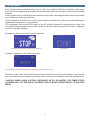
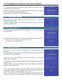
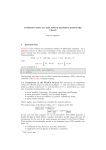
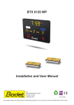
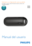
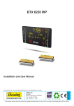
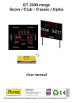
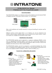
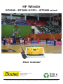
HF Whistle
BT6000 - BT5000 HF/FIL - BT5000 wired
User manual
BP1
49340 TRÉMENTINES FRANCE
Tel. 02 41 71 72 00
Fax 02 41 71 72 02
www.bodet.com
Ref. 607010C
1
Upon reception, check the product was not damaged during
shipping, and report any such damage to the carrier.
Table of contents
1. Presentation of the HF whistle
3
1.1 Referee terminal and HF whistle scoring .............................................................................................................. 3
1.2 Battery charger ...................................................................................................................................................... 3
2. Connecting the whistle keyboard
4
2.1 Connection on BT6000 keyboard .......................................................................................................................... 4
2.2 Connection on BT5000 HF/FIL keyboard .............................................................................................................. 4
2.3 Connection on BT5000 wired keyboard ................................................................................................................ 4
3. Using the HF whistle during a game
5
3.1 Installing the referee terminal unit ......................................................................................................................... 5
3.2 Start-up for the game ........................................................................................................................................... 5
3.3 Preparation and testing before game .................................................................................................................... 5
3.4 Operation .............................................................................................................................................................. 6
4. Changing the channel, role and network
7
4.1 Changing the channel ........................................................................................................................................... 7
4.2 Changing the role .................................................................................................................................................. 7
4.3 Creating a network ................................................................................................................................................ 7
4.4 Communication disturbance .................................................................................................................................. 8
4.5 Technical information ............................................................................................................................................. 8
BT6000 main keyboard
BT5000 HF/FIL main keyboard
BT5000 wired main keyboard
This document describes the operation and procedures of use of the audio transmission system
used to detect referee whistles.
This function is effective only when using official whistles: Fox 40, Mini 40 or Molten Dolfin Pro.
2
1. Presentation of the HF whistle
1.1 Referee terminal and HF whistle scoring
Official whistle
Each referee has :
• One radio terminal with a 1000 mA h rechargeable
battery.
• A microphone and a timer start button.
• A fastening belt or holster.
Referee terminal
Microphone
To keyboard
Timer start button
Power supply 230V
Earpiece
ON/OFF key
The HF whistle keyboard with its backlit LCD display
indicates :
OK key
Parameter
validation
Start timer key
(parameter choice)
Stop timer key
(parameter choice)
Menu access key
•
•
•
•
The state of the START / STOP timer.
The number of referees in communication (1 to 6).
Each whistle stop and which referee stops the time.
The communication channel (C01 to C03).
1.2 Battery charger
• The recharge set for 1 to 5 batteries lasts 2 to 3 hours.
• The average time of use of a battery is 2 basket ball games with a stop between both games. However, batteries
should be recharged between each game.
• Connect the power supply unit to the power grid. When plugged in, the 5 leds at the front of the charger will first turn
orange, then they will turn off one after the other, and finally simultaneously flash green.
• To remove or change the battery, push it towards the top of the terminal then lift it.
• Place the batteries on the charger (gold contact side down). When the battery has
been dectected, the corresponding led turn red. If the light is not on, check that the
battery has been correctly positionned.
Meaning of led indications
Steady red
Charging
Steady green
Battery charged
Flashing red
Battery defect. Replace the battery
Flashing green
Battery absence
Flashing green and red Battery temperature is outside of the autorised range. Charging
turn
is suspended until the correct temperature has been reached
Flashing orange
Unrecognised battery. Check the battery’s reference
3
2. Connecting the whistle keyboard
2.1 Connection on BT6000 main keyboard
Connect the HF whistle keyboard onto the DIN plug of the BT6000 main keyboard.
DIN plug main keyboard
Main keyboard BT6000
HF whistle keyboard
2.2 Connection on BT5000 HF/FIL keyboard
Open the main keyboard by unscrewing the 4 screws.
Remove the connector from the old Start/Stop controller. Connect the connector of the new Start/Stop
controller instead.
Connect the DIN connector of the new Start/Stop controller onto the HF whistle keyboard.
Start/Stop controller
Start/Stop controller connector
BT5000 HF/WIRE main keyboard
HF whistle keyboard
2.3 Connection on BT5000 wired keyboard
Connect the DIN connector of the interface unit onto the HF whistle keyboard.
Connect the jack connector of the interface unit onto the BT5000 wire main keyboard.
Interface unit
JACK connector main keyboard
BT5000 wire main keyboard
4
HF whistle keyboard
3. Using the HF whistle during a game
3.1 Installing the referee terminal unit
Pass the microphone under the referee’s shirt and attach it to the collar. Attach the start button and
the radio terminal to the referee’s waist.
Connect the connector while ensuring the terminal is inserted in the holster. Start the terminal by a
long press on the ON button.
The sensitive keyboard on the referee terminal is not used during the game. It is locked automatically
when started to avoid untimely pressing.
3.2 Start-up for the game
Connect the HF whistle keyboard to mains and to the main keyboard.
Switch on the main keyboard (press the start button and set the game start for the sport required) as
well as the HF whistle keyboard and the referee terminals (long press on the ON key).
Check timer start/stop control on the HF whistle from the main keyboard. Start the referee terminals
after their installation with each referee.
On the display of the HF whistle keyboard, check the number of terminals communicating (1 to 6
according to the number powered on).
The referee terminal number 1 is required for proper operation with minimum 2 referee terminals in
the network (information in the top left corner of each view). Turn off unused terminals. If the terminal
1 is down, take a spare terminal and change its role into WHISTLE 1 (see § 4.2).
3.3 Preparation and testing before game
Before starting the game, test the whistle and timer start for each referee from several points of the
game field.
The table operator must check proper synchronization of the 2 keyboards (HF whistle keyboard and
main keyboard) (timer start or stop mode), after synchronization, only the HF whistle keyboard must
be used to activate the timer.
Check the battery charge status of the terminals and make sure they use the same channel.
The timekeeper confirms proper operation to each referee. The game can start.
24 sec keyboard
HF whistle keyboard
Main keyboard
5
Secondary keyboard
3.4 Operation
Each referee with his official whistle (Fox 40, Mini fox or Molten Dolfin pro) whistles, which stops
the timer on the display board instantly. Several whistle blows have no effect, as the timer is already
stopped.
From his start button, each referee can restart the timer. Also, pressing the start button several times
only confirm the timer was launched.
These operations are effective in radio communication between the referees and the timekeeper,
regardless of the position of the referees.
The timekeeper sees on the LCD screen of the HF whistle keyboard the automatic timer stop, and
the referee having whistled. He can take control of the timer at any time using the 2 start – stop keys
on the HF whistle keyboard.
Examples of display on the HF whistle keyboard
3 terminals active, channel 01, whistle stop by referee N°1
Timer started
Example of display on the referee terminal
Channel number, whistle number, battery charge and number of terminals in the network
Reminder on the rules: at the end of the game (time below 2 minutes), the timekeeper must stop the
timer manually whenever points are scored, as the referees do not whistle timer stop at each score.
CAUTION: WHEN USING A BT5000 KEYBOARD (HF/FIL OR WIRED), THE TIMER STOPS
AUTOMATICALLY AT THE END OF A PERIOD. THE HF WHISTLE MUST BE SET TO THE STOP
MODE.
6
4. Changing the channel, role and network
The keyboard must be unlocked to have access to the menu of the
referee terminal (User menu).
Unlocking: long press on OK (on each referee terminal). The ‘key’ symbol
in the lower left of the display disappears.
Menu access: long press (> 2s) on the MENU key.
4.1 Changing the channel
In the user menu, select ‘Channel’ by moving using the + or – keys, and
validate by pressing OK.
In ‘Chan. setting’, select the channel required C01, C02 or C03 and
validate by pressing OK.
4.2 Changing the role
In the user menu, select ‘Role’ by moving with the + or – keys and validate
by pressing OK.
In ‘Role setting’, select the role required, and validate by pressing OK.
• Whistle 1 to 6 corresponds to the referee terminal 1 to 6.
• Table KBD is the HF whistle keyboard.
4.3 Creating a network
This menu is used to create an encrypted HF network between the
terminals.
This procedure must be applied simultaneously with all referee terminals
and the HF whistle keyboard.
In the user menu, select ‘Network’ by moving with the + or – keys and
validate by pressing OK.
In ‘Network encryption’, select start and press OK. Set the referee terminal
number 1 last.
When all terminals and the keyboard display ‘Succeeded’, validate the
procedure by pressing OK.
Note : the referee terminal n°1 displays ‘please wait until procedure has
succeeded’ during the entire procedure and never displays ‘Succeeded’.
Press OK if all other terminals display ‘Succeeded’.
Note : after each menu access, lock the keyboard of each terminal with a
long press on OK, a key is displayed in the lower left corner of the display.
7
4.4 Communication disturbance
In case of radio disturbance, the communication frequency can be changed on all devices. Number
of channels : 3.
In case of malfunction of one of the referee terminals, even with a frequency change, a spare referee
terminal can be allocated to a referee while ensuring there is always a terminal number 1 (set one
of the active terminals to WHISTLE 1 using ‘Role setting’).
4.5 Technical information
The system between the referee terminals and the HF whistle keyboard operates in the 863-865
MHz band (2 10 mW channels available) and in the 869.4 – 869.65MHz sub-band (1 200 mW
channel available).
C1 : 869,525 MHz / 200 mW
C2 : 864.5 MHz / 10 mW
C3 : 863.5 MHz / 10 mW
Each terminal has a role number from 1 to 6 (referee number 1 to number 6).
Each system requires minimum 2 referee terminals running, including number 1. All referee terminals
and the HF whistle table keyboard must be set to the same channel.
Each referee terminal can be set on site to change the channel, role, and be associated with the
existing network without being returned to the factory.
To secure operation during a game, communication between all devices (referee terminals and
HF whistle keyboard) is encrypted. The encryption procedure creates a network linking all referee
terminals with the HF whistle keyboard. Once the network created and running, no other device can
be inserted.
No other whistle model will be received remotely from a referee.
8