1
N ATHAN D . D UNN, P.E.
H. L OWRY TIU BBLE, ] R., P.E.
WI LLIAM
W
F.
H ODGES , P.E.
M ICHAEL STUBBS, P.E.
R . B RANT LANE, P.E .
CLI NT
L.
-
- HODGES, HARBIN, - NEWBERRY & TRIBBLE, INC.
C ouRSON, CHMM
K. MATTH EW CH EEK, P.E.
Consulting Engineers
R YAN
5.
WILLOUG HBY, P.E.
WILLIAM A. G RAN ICH, P.E.
R OBERT D. H ELLER, CHMM
ERI C P. j ACKSON, P .E.
D AVID E . BATTSON,
P.E.
D AN IEL E. CH EEK, P.E.
R YAN s . P ETERS, P .E .
K EVIN G . B ERRY, P.E.
W ILLIAM M . R EESE,
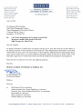
June 11,2015
Mr. Benjamin (Ben) Gauthier
Solid Waste Management Program
Waste Management & Prevention Division
1 National Life Dr - Davis 1
Montpelier, VT 05620-3704
Re:
Cell 3 Odor Maintenance & Preventative Action Plan
Moretown Landfill, Solid ·w aste ID #WA470
HHNT Project No. 1210-372-01
Dear Mr. Gauthier:
On behalf of Moretown Landfill and in accordance with the June 4, 2015 letter from the Vermont Office of
the Attorney General, we have attached a revised draft Cell 3 Odor Maintenance & Preventative Action Plan
("Odor Plan") for your review. For convenience, we have attached a draft plan that has track changes shown
and to assist in ANR review. If you have additional comments, please let me know or if this version of the
Odor plan is approved, we will provide a final copy with all changes shown adopted for formal approval.
Please feel free to contact me if you have any additional questions.
Sincerely,
HODGES, HARBIN, NEWBERRY & TRIBBLE, INC.
Professional Engineer
WMS/cw
Enclosure
cc.:
Bill Kernan, MLI (w/ enclosure)
Adam Sowatzka, Esq., King & Spalding (w/ enclosure)
Chris Roy, Esq., Downs Rachlin Martin PLLC (wl enclosure)
Dave Rettell (w/ enclosure)
Dave Lavender (w/ enclosure)
Michael Slattery (w/ enclosure)
3920 Arkwright Road, Suite 101 • Macon, Georgia 31210 • (478) 743-7175 • Fax (478) 743-1703 • www.hhnt.com
P.E.
Cell 3 Odor Maintenance & Preventative Action Plan
Moretown Landfill, Inc.
Moretown, Vermont
Submitted to:
State of Vermont
Air Pollution Control Division
Davis Building – 2nd Floor
One National Life Drive
Montpelier, VT 05602
For:
Moretown Landfill, Inc.
19 Kaiser Drive
Waterbury, VT 05676
Prepared by:
Tech Environmental, Inc.
303 Wyman Street, Suite 295
Waltham, MA 02451
Revisions for June 11, 2015 Prepared by Hodges, Harbin, Newberry, & Tribble, Inc.
REV. June 11, 2015
REV. March 20, 2015
REV. April 25, 2014
November 15, 2013
TABLE OF CONTENTS
Section Contents
Page
INTRODUCTION
1
1.1 Background ...................................................................................................................... 2
1.2 Regulatory Requirements................................................................................................. 4
1.3 Facility Contacts .............................................................................................................. 5
2.0 ODOR BASELINE AND ODOR AWARENESS
6
2.1 Odor Primer ..................................................................................................................... 6
2.2 Hydrogen Sulfide ............................................................................................................. 7
2.3 Odor Nuisance Threshold ................................................................................................ 8
2.4 Odor Training................................................................................................................... 9
2.5 Waste Acceptance & Odor Potential ............................................................................... 9
2.6 Odor Patrols ................................................................................................................... 10
2.7 Surface Emission Monitoring .................................................................................... 1110
2.8 Odor Complaint Program............................................................................................... 12
3.0 LANDFILL GAS COLLECTION SYSTEM
1514
3.1 Gas Collection System Evaluations ........................................................................... 1514
3.2 Condensate Checks & Gas Balancing........................................................................ 1615
3.3 Gas Well Monitoring and Balancing ......................................................................... 1715
3.4 Gas Well Maintenance ........................................................................................... 181716
3.5 Flare Maintenance ...................................................................................................... 1917
3.6 Preventative Maintenance .......................................................................................... 2018
3.7 Pump Maintenance..................................................................................................... 2019
4.0 MONITORING & RECORD KEEPING
2019
4.1 Landfill Liner Monitoring .......................................................................................... 2019
4.2 H2S Monitoring .......................................................................................................... 2019
4.3 Stormwater Management Evaluations ....................................................................... 2019
4.4 Leachate Management Plans...................................................................................... 2120
4.5 Record Keeping ......................................................................................................... 2120
4.6 Emergency Reporting ................................................................................................ 2221
5.0 SPECIFIC ODOR CONTROL PROCEDURES
2322
5.1 Odor Control for Breeching the Cap.......................................................................... 2322
5.2 Odor Control for Excavating into Waste ................................................................... 2322
5.3 Odor Control for Clean Out or Wellhead Replacements Procedures ........................ 2322
5.4 Odor Control for Replacing Wells ............................................................................. 2423
6.0 LONG-TERM FINANCIAL COMMITMENT TO ODOR CONTROL
2524
1.0
APPENDICES
Appendix A
Appendix B
Appendix C
Appendix D
Appendix E
Appendix F
Appendix G
Appendix G
Air Permit
Odor Patrol Log
Odor Complaint Response Form
Surface Emissions Monitoring Plan
O&M Manual for LFG and Condensate Management Systems
Environmental Monitoring Location Plan
Hazardous Air Sampling Results
Activity Frequency Table
i
Moretown Landfill, Inc.
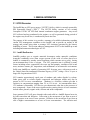
1.0
Cell 3 Odor Maintenance & Preventative Action Plan
INTRODUCTION
Pursuant to Paragraph 23 of the Consent Order and Judgment Order, Docket No. 37-3-13 Vtec
VTEC(“CO”), which was entered into between the Vermont Department of Environmental
Conservation (“VTDEC”) and Moretown Landfill Inc. (“MLI”), the following is the Odor
Maintenance & Preventative Action Plan (“Odor Plan”) for Cell 3 and will be applicable until
post closure certification.
This Odor Plan takes into consideration that portions of Cells 1, 2, and 3 are not yet fully capped.
In the future, the frequency of many tasks to monitor odor will decrease as outlined in this Odor
Plan because the potential for rapid changes in the odor baseline will be drastically reduced after
temporary and permanent capping is completed. Further, Tthere will be a second decline in odor
monitoring frequency, once the hydrogen sulfide level (“H2S”) and the landfill gas (“LFG”)
begin to naturally decrease from Cells 1 to 3. The reduction of frequency of various tasks
generally involves performance based criteria as discussed below. However, MLI’s commitment
to odor control will continue as demonstrated by the Company’s long-term financial commitment
to odor control, but the frequency of certain tasks will be reduced.
1
Moretown Landfill, Inc.
Cell 3 Odor Maintenance & Preventative Action Plan
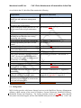
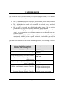
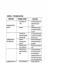
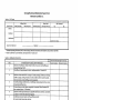
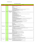
As set forth in the CO, this Odor Plan contains the following:
Requirement
Location in Odor Plan
Operations and maintenance manual for the
landfill gas and condensate management
systems
Gas well monitoring and balancing
procedures and responsibilities
Update to the post-closure plan for Cell 3 to
include annual odor and gas maintenance
costs
Preventative maintenance provisions
Ongoing monthly gas system monitoring,
including but not limited to the existing
monitoring and reporting
Record keeping and reporting requirements
Standard operational procedures for odor
control
An annual budget allotment for odor control
Gas well pump and well
replacement/addition plan
Gas well liquid level monitoring schedule
Odor control Standard Operating Procedure
(“SOP”) for any activities that breach the
cap, excavate into waste, or require removal
of cleanouts or wellheads
Leachate odors control procedures
Odor patrol/inspections plan
Procedures in case of complaints or
confirmed off-site odors
Gas system extraction and combustion plant
maintenance
Ongoing monitoring plan for methane and
hydrogen sulfide at compliance points
H2S and methane action levels and
minimum response actions at various action
levels and averaging times
Hazardous air sampling
See Section 3.2, Appendix E
1.1
See Section 3.3 and Section 3.4, Appendix E
See Section 6.05.5
See Section 3.6
See Section 4.1 and Section 4.2
See Section 4.5 and Section 4.6
See Section 5
See Section 6.05.5
See Section 3.1, Appendix E
See Section 3.1, Appendix E
See Section 5.1, Section 5.2 and Section 5.3
See Section 4.3 and Section 4.4
See Section 2.62.5, Appendix B, Appendix F
See Section 2.8, Appendix C
See Section 3.4 and Section 3.5, Appendix E
See Section 2.7, Section 3.3 and Section 3.5,
Appendix B, Appendix D, Appendix E
See Section 2.7
Section 7.0, Appendix G
Background
MLI’s facility provides solid waste disposal services to the Mad River Resource Management
Alliance, which consists of the towns of Duxbury, Fayston, Moretown, Northfield, Roxbury,
Waitsfield, Warren and Waterbury. The facility currently consists of fourfive waste disposal
areas (three closed and capped, and one lined landfill in the process of being closed). Cells 1 and
2
Moretown Landfill, Inc.
Cell 3 Odor Maintenance & Preventative Action Plan
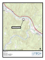
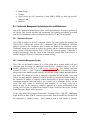
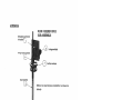
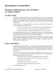
2 are closed while Cell 3 was actively receiving waste until July 15, 2013. The location of the
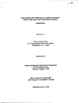
landfill is shown in Figure 1-1.
Historically, the property was operated as a sand and gravel extraction business. The property
owner then began to accept waste and ultimately developed the property into the “town dump,”
which was essentially an unlined landfill. We understand that a landfill of some type has been
operated on the property for at least the last 30 years. The unlined landfill was operated until
approximately 1993/1994. The first lined landfill cell (Cell 1) was constructed at the facility
when the unlined landfill was closed. Cell 1 was operated from this time until approximately
1999. Afterwards, Cell 2 was constructed and began operating. The landfill expanded again in
2005/2006 by constructing the first sub-cell of Cell 3.
The landfill is also home to a landfill gas to energy (“LFGTE”), which is owned and operated by
PPL Renewable Energy, LLC (“PPL”). The LFGTE facility consists of two existing Caterpillar
G3520C LE landfill gas fired internal combustion engine generators. Any excess LFG collected
and not combusted in the engines, as well as generated during periods of the engines may be offline, is combusted by an on-site flare.
MLI initially intendeds to pursue the expansion of the landfill, through an application for a 4th
Cell (“Cell 4”). The Cell 4 expansion project will consist would have consisted of constructing a
new 27 acre lined landfill cell (including the “lay back” area) to the south of the existing landfill,
which will would have provided approximately 3.4 million cubic yards of airspace. This Odor
Plan will be replaced by the Odor Plan for Cell 4, when the certification is approved by the State
of Vermont Agency of Natural Resources Department of Environmental Conservation
(“VTDEC”). The Cell 4 application has been withdrawn by MLI. This Odor Plan is intended to
serve as the Odor plan until the facility receives final closure and outlines operations for odor
control during post closure until this plan is updated as part of the final post closure plan required
as part of the ANR March 6, 2015 letter.
Given that Cell 3 is no longer receiving waste, odor is now managed primarily by MLI through
the use of an active gas collection and control system (“GCCS”). Previously, the application of
daily cover and intermediate cover and the prohibition of the disposal of odoriferous wastes were
also used to control odor. Although no longer accepting waste, MLI continues to retain
LFG/odor technicians as part of the operational staff. These LFG/odor technicians maintain,
operate, and monitor the LFG collection and control system and also address odor issues related
to the landfill.
This Odor Plan will be implemented and will remain valid for the landfill lifecycle unless it is
superseded by a new Odor Plan (i.e., an approved Odor Plan for Cell 4) (i.e. updated Odor Plan
at Post Closure Plan approval). It assumes that Cells 1, 2 and 3 will be capped in the very near
future. Once that occurs, odor patrols and other odor related activities will still be necessary, but
the frequency will be much less because the potential for a rapid change in baseline odor is much
less. Similarly, as the landfill gas created in Cells 1 through 3 decreases with time after
temporary and permanent capping, the frequency requirements will continue to decrease. The
timeline ranges are discussed throughout this Odor Plan.
3
Moretown Landfill, Inc.
1.2
Cell 3 Odor Maintenance & Preventative Action Plan
Regulatory Requirements
Emissions of odor from the landfill are regulated by the facility’s Air Pollution Control Permit
(“Air Permit”) issued by VTDEC, and included in Appendix A. The permit states the following
as an emission limitation:
(12) Nuisance and Odor: The Operator shall not discharge, cause, suffer, allow,
or permit from any source whatsoever such quantities of air contaminants or
other material which will cause injury, detriment, nuisance or annoyance to any
considerable number of people or to the public or which endangers the comfort,
repose, health or safety of any such persons or the public or which causes or has
the tendency to cause injury or damage to business or property. The Operator
shall not discharge, cause, suffer, allow or permit any emissions of objectionable
odors beyond the property line of the facility.
The Odor Plan, in addition to meeting the requirements of the CO, is designed to meet the
requirements of the current Air Permit.
Additionally, emissions of odor from the landfill are regulated by the following VTDEC Solid
Waste Management Rules:
§6-606(b)(2)(J) Discrete Disposal Facilities: Facilities shall assure the control and
treatment, if determined necessary by the Secretary, of gases resulting from the
decomposition of wastes to prevent hazards to public health and safety, the environment,
or the creation of a nuisance.
§6-701(6) General Standards Applicable to All Facilities: The owner and operator shall
take all steps necessary to prevent and/or control spills, nuisance dust, vectors, wind
blown debris, and odors.
§6-702(d)(5) Discrete Disposal Facilities: With the exception of construction and
demolition waste landfills, cover material shall be in place at the end of each operating
day, or at more frequent intervals if necessary, to control disease vectors, fires and odors,
to prevent blowing litter, and to discourage scavenging by animals, without presenting a
threat to human health and the environment. Grading shall be accomplished to prevent
ponding. At least a six inch thickness is required when earthen material is used as cover
material. In all areas other than the working face which have not received waste material
in any given operating day, the owner or operator shall take all steps necessary to ensure
that the cover material remains functional and stable until such time as the final cover
system is installed. Construction and demolition waste landfills shall maintain cover
pursuant to the cover requirements contained within facility’s approved facility
management plan.
4
Moretown Landfill, Inc.
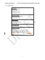
1.3
Cell 3 Odor Maintenance & Preventative Action Plan
Facility Contacts
Main Office:
Moretown Landfill, Inc.
19 Kaiser Drive
Waterbury, VT 05676
(802) 244-1100 – voice
(802) 244-5133 – fax
Operations Manager:
William Kernan, Ops. Manager
(802) 244-1100, ext. 227
(802) 279-1315 – cell
Corporate Office:
90 Ford Wade Road
Ponte Verda, Florida 32081
(904) 737-7900
Community Hotline:
(800) 981-4251
Emergency Numbers:
Fire: 911 or (802) 496-3731
Police: 911
Hazardous Substance Spills: (800) 641-5005
Emergency Management Office: (800) 347-0488
Solid Waste Management Program: (802) 241-3888281138.
5
SITE LOCATION
N
Based on USGS topographic map for Middlesex, Vermont Quadrangle
Figure 1-1.
Site Locus
Moretown Landfill, Inc.
Moretown, Vermont
Not to Scale
Moretown Landfill, Inc.
2.0
Cell 3 Odor Maintenance & Preventative Action Plan
ODOR BASELINE AND ODOR AWARENESS
As landfill waste degrades and stabilizes, it creates smaller compounds from larger compounds
and those smaller compounds are more volatile. Many of these compounds, especially those
containing sulfur, are readily detectable by the human olfactory system – our noses. Landfill
operations must be managed in a way that these compounds are emitted at levels that alone, or in
conjunction with dispersion, do not create nuisance conditions at the nearest neighbors.
Gases generated in a landfill consist mainly of methane and carbon dioxide. However, there are
other trace gases generated. These trace gases only become an issue when they have a low odor
detection threshold or are extremely persistent.
Before someone can understand potential changes in odor, the odor baseline must be fully
understood. This section is included to help employees understand the basics of odor, how to
continuously assess odor as part of their daily activities, and to understand the odor baseline and
how odor varies.
The odor baseline will be observed by a designated MLI employee each work day during daily
odor patrols and supported with quantitative, low-range H2S sampling at the discretion of the
employee based on odor presence. More information regarding baseline observations are detailed
in the Odor Patrols section below.
2.1
Odor Primer
Sensitivity to odors varies among the population. An odor that is noticed by or is offensive to
one person may not be noticed by or offensive to another. It has been estimated that the
olfactory sensitivity for 1 in 20 people is outside of what is considered the “normal” range and
oftentimes individuals who have a poor sense of smell are never aware of their desensitized
olfactory system. Conversely, some individuals have an extremely keen sense of smell. Factors
that affect one’s sensitivity to odors include genetics, age, gender, experience, and environmental
influences.
Since odor detection and sensitivity can vary greatly among individuals, sensitivity screening can
be conducted to determine whether someone is in the “normal” (average) range. Odor threshold
screening should be conducted to determine whether those individuals who are formally charged
with assessing the odor baseline and tracking its changes surveys possess an adequate olfactory
threshold and are capable of conducting an accurate assessment of current odors. It can also be
used to assess those individuals that are ideally suited to respond to odor complaints.
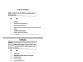
Four attributes of the sense of smell have been defined to classify odors:
Concentration/Intensity - strength of the odor;
Pervasiveness - change in intensity upon dilution;
Character - description of the odor; and
Hedonic Tone - relative pleasantness of the odor.
6
Moretown Landfill, Inc.
Cell 3 Odor Maintenance & Preventative Action Plan
The concentration, or intensity, of an odor describes its strength; the intensity of an odor is
unrelated to its character or pleasantness. In general, more reactive compounds have higher odor
intensities. Odor concentration is typically highest at the source and disperses as it travels away
from the source. However, odors from like sources can be additive. The pervasiveness of an
odor is its rate of change in intensity upon dilution. The intensity of some odors will quickly
diminish when released, while other odors will show very little decrease in concentration with
dilution. The character of an odor best describes the source of that odor and typifies the human
reaction to it.
The hedonic tone of an odor describes its relative pleasantness to the human nose. Two odors
may both be very strong with similar odor intensities, but one may be pleasing to the human nose
(i.e., flowers, chocolate, coffee) having a highly positive hedonic tone, while the other may be
very offensive to the human nose (i.e., skunk, sewage, garbage) and have a highly negative
hedonic tone. The character and hedonic tone of LFG are both considered negative and their
degree of unpleasantness can contribute to community nuisance issues.
The remainder of this section of the Odor Plan is designed to establish methods to reduce the
intensity, persistence, frequency, and duration of odor events.
2.2
Hydrogen Sulfide
The simplest reduced sulfur compound is “H2S”. H2S is often used as a surrogate for total odor.
It is an important indicator of decomposing wastes typically found in landfills and an excellent
compound to track or trace odor control effectiveness. H2S creates an unpleasant odor, often
described as a “rotten egg” smell. It also has one of the lowest odor thresholds for any
compound emitted from landfills.
Landfilled municipal solid waste has a mixture of compounds. Typically, the odorous
compounds include reduced sulfur compounds with the simplest two being H2S and methyl
mercaptan, reduced nitrogen compounds including ammonia and triethylamine, and to a lesser
extent reduced phosphorous compounds, VOCs, and fatty acids. Because H2S is not the only
potential odorant of concern from a landfill, this Odor Plan also includes periodic considerations
of other reduced sulfur compounds to estimate odor nuisance potential.
Typically there are two distinctive odors at a landfill related to aerobic decay (fresh garbage
odor) and anaerobic decay (reduced sulfur odor). The fresh garbage odor is not as persistent as
the reduced sulfur odor, meaning if you have equal concentrations of each at the landfill, as they
get diluted the less persistent one will fade away sooner to non-detectable levels.
H2S and other reduced sulfur compounds’ persistence, combined with unpleasant character and
low odor detection thresholds, make up most of the odor potential from a landfill. If a
monitoring program focuses on these compounds, most on-site odor concerns can be identified
before they become off-site nuisances.
The two primary reduced sulfur compounds formed, as byproducts of landfill degradation, are
the two simplest reduced sulfur compounds, H2S and methyl mercaptan. These are often used as
surrogates for examining the extent of landfill odor. In a laboratory, environment samples are
analyzed for these two compounds and up to 20 reduced sulfur compounds in the part per billion
7
Moretown Landfill, Inc.
Cell 3 Odor Maintenance & Preventative Action Plan
(“ppb”) level. Unfortunately, however, in the field we are limited to the sensitivity of the
monitoring equipment available.
Most H2S field detectors use electrochemical sensors that are sensitive to single digits in the
parts per million by volume (“ppmv”) range. Unfortunately, humans can detect H2S down to
single digit parts per billion by volume (“ppbv”) range and mercaptans to the parts per trillion
(“ppt”) level. Although the threshold for odor nuisance is subject to great debate, the nuisance
threshold for a single short-term event is below the single ppmv range of standard
electrochemical sensors. Thus, a combination of the nose and other instruments are necessary.
2.3
Odor Nuisance Threshold
It is not reasonable to expect “zero odors” from a landfill, nor is it possible to collect all
emissions from all sources. Maximizing odor collection at a landfill is most difficult during
waste disposal. When waste is first placed, it cannot be effectively captured or safely connected
to the LFG system, even if wells are installed as waste is placed. Pulling air from an active area
before LFG production is adequate can cause air entrainment. If fresh air is mixed with typical
LFG inside the landfill hazardous conditions can occur. These hazards include a possible
explosion or an underground landfill fire. To minimize hazardous conditions, landfill operators
must slowly add new areas to the system only when there is minimal air entrainment. Given that
Cell 3 is no longer accepting waste, this is no longer a concern.
It is also important for operators to realize that they may become desensitized to certain odors
during the day and over time. An operator working on open wells likely will experience at least
some amount of temporary olfactory fatigue. Thus, assessing off-site odor potential may not be
as effective until after some time is spent away from the well field. It is not uncommon for
someone from a facility that has been exposed to on-site odor to travel off-site to investigate an
odor complaint and come to the conclusion that the odor is “not that bad.”
Nuisance conditions are not defined by detectable odor, but are defined by odor that causes
someone to change their daily behavior because of the odor. For example, if a person drives by a
facility and smells a faint odor, it would not be considered a nuisance since it lasted for only a
moment while the driver passed the facility. The odor did not change the driver’s actions.
However, if the odor was so intense that it caused a driver to turn around or to change future
driving patterns to avoid it, the odor could be considered a nuisance.
In summary, an operator should always be aware of the odor baseline on-site as he completes his
normally daily tasks. If this baseline changes, it should be noted. If it increases dramatically, the
nuisance potential off-site should be explored by someone that is not immediately desensitized.
will be explored by an employee that is not desensitized to the odor or the use of the third party
odor responder. The employee / responder will evaluate the odor to the north of the landfill along
Route 2, the MLI office, and other historic odor locations that are determined at the discretion of
the operator. Odors will be documented in a Daily Odor Patrol Form and will be kept on site for
record keeping. Once the odor source is confirmed, corrective actions (as detailed in this plan)
will be conducted to resolve the odor issue.
8
Moretown Landfill, Inc.
2.4
Cell 3 Odor Maintenance & Preventative Action Plan
Odor Training
It is possible to train someone to better understand their olfactory senses. To properly analyze an
odor event, individuals need to understand the basics of odor, including how and what we
actually smell when exposed to odorous compounds in the air. The goal of odor training is to
provide individuals with the information that they need to better understand odor and how to
recognize and characterize it. This, in turn, will help the trained individuals to better manage and
respond to odor events and/or complaints. This type of training usually includes:
Instruction on the role of personal perception;
The differences between typical odors and each of their potentials; and
The methods to recognize various odors.
Individuals responding to odor complaints or conducting odor patrols can more accurately
determine the source of any one particular odor if they are well-informed about the scents of
common odors and the way in which odors are released and transported to off-site locations. In
some cases, odors initially believed to derive from a very proximate location are actually from
other sources that are much further away or are a culmination of smaller sources that together
produce a considerable odor. Many times, multiple sources may be adding to the total odor
dynamic in a neighborhood, while the local community assumes that any and all odor is from a
single source. A trained odor investigator is typically able to determine where an odor is coming
from, and if not, at least correlate the odor to its rightful source.
Training will be conducted for landfill staff so that they can better understand odor, human
perception, the differences between landfill odors and odor potential. This will help the landfill
staff recognize and characterize odor increases more quickly, which will lead to a faster
response. The training will include information on what causes odors, the role of personal
perception, and recognizing odors. Staff will be trained in monitoring H2S levels using a handheld instrument, such as a Jerome analyzer, and how to pinpoint the source of odors by using the
meter.
Since odor detection and sensitivity vary a great deal among individuals, staff will be screened
for their odor sensitivity to confirm that the staff is in the “normal” range. It has been estimated
that the olfactory sensitivity for 1 in 20 people is outside of what is considered a “normal” range.
Staff members who are in the “normal” range will be considered qualified to receive the training.
2.5
Waste Acceptance & Odor Potential
Cell 3 is no longer accepting waste as of July 15, 2013. Thus, this section is no longer
applicable.
9
Moretown Landfill, Inc.
2.6
Cell 3 Odor Maintenance & Preventative Action Plan
Odor Patrols
As part of this Odor Plan, MLI will conduct an odor survey each business day until Cells 1
through 3 are temporarily or permanently capped.1 Odor surveys shall be completed at a
minimum frequency of two times per week after the permanent capping system is in place , and
personnel are no longer on-site daily. If after 60 consecutive days and no odor complaints have
been confirmed, the odor patrols will be reduced to when personnel are on-site for post closure
activities or after confirmed odor complaints. The daily odor surveys, over time, will establish an
“odor baseline” for the facility. This odor baseline will allow staff to more quickly recognize
and respond to an incident of increased odor on-site in the future and likely before it becomes an
off-site concern. Staff conducting the surveys will be trained in odor monitoring and odor
identification, as described in more detail below.
The survey should be conducted in the morning, before the surveyor has become desensitized to
odor. Monitoring in the morning is also beneficial from a meteorological perspective, since
odors can experience less dispersion after a still and clear night. The on-site weather station is
not operable and will be replaced. The weather station to be used is a Davis Instruments Model
6250 Vantage Vue Wireless Weather Station capable of gathering the data mentioned in this
plan. This weather station will be installed at the site no later than August 1, 2015.
The survey should be conducted along the perimeter of the landfill so that different wind
directions and different areas can be examined. As the surveyor traverses the perimeter, he
should record any notable odors on the Odor Patrol Log. A copy of the Odor Patrol Log
template is included in Appendix B. This information will help establish the areas of the landfill
that have a higher odor potential, based on both landfill activity and meteorological conditions.
The landfill should record the following information on days when odor patrols are completed:
Wind speed and direction (from the landfill weather station);
Weather observations (cloud cover, precipitation, haze, etc.); and
Landfill activity.
When odors are detected during the odor patrol, the following information should be recorded:
Description of odor character and intensity;
Measured value of H2S (using a low range analyzer, such as a Jerome);
Weather observations (cloud cover, precipitation, haze, etc.);
Wind speed and direction (from the landfill weather station); and
Any landfill activity occurring.
An off-site patrol will be completed upon confirmation of detected odors on-site by the operator.
An employee will evaluate off-site conditions at locations at least to the north of the landfill
along Route 2, the MLI office, and other historic odor locations determined at the discretion of
1
Please note that it is not important that this daily task be done each and every day, but that it be a daily activity
when time or conditions permit. The important thing is that the staff does this consistently, so that they can
understand the changes in odor with many different weather conditions.
10
Moretown Landfill, Inc.
Cell 3 Odor Maintenance & Preventative Action Plan
the operator. Odors will be documented in the Odor Patrol Log and will be kept on site for record
keeping.
The information from these daily surveys should be compiled to generate an odor baseline and to
target areas of the landfill with greater odor potential. To that end, data from the Odor Patrol
Log will be maintained in a database.
If odor and H2S levels are found to dramatically exceed typical baseline conditions during the
perimeter surveys, a systematic investigation for areas of excessive LFG emissions (“hotspots”)
of the landfill should be conducted. These surveys could be conducted over several days under
different meteorological conditions to locate potential sources of odor. The survey should be
conducted by systematically traversing the landfill. Once a hotspot is identified, an H2S reading
should be taken, preferably using an isolation chamber to avoid sample dilution from wind. If no
hotspots can be identified, H2S readings should be taken from regularly spaced intervals over the
landfill.
Once a hotspot has been identified and characterized, a remediation strategy should be
determined, depending on the hotspot and its proximity to the GCCS. Depending on the
magnitude of the hotspot, sealing or inclusion in the GCCS should be considered.
It should be noted that the potential for hot spots will drop dramatically as areas are closed and
temporarily or permanently capped. That is why MLI prefers a “cap as you go” approach to cell
operations. In the near future, Cells 1 through 3 will be covered with at least temporary
permanent capping. Once this occurs, the staff may determine that the odor baseline does not
change much on a daily basis and the odor survey only need to be completed a few once times a
week. Eventually, the odor patrols will be done on a weekly or monthly basis as LFG production
subsides with time. The key will be to maintain enough odor patrols, so that any change in odor
will be readily observed.
2.7
Surface Emission Monitoring
Although H2S has a low odor threshold and methane is odorless, methane is typically present in
LFG at a significantly higher concentration than H2S. As such, the landfill is monitored for
methane as a surrogate for LFG emissions. The landfill is currently monitored on a monthly
basis. This monthly monitoring will continue until the Cell 3 temporary or final permanent
capping is in place. After the completion of final closurethat, the monthly monitoring will
continue for a period of three months, and monthly thereafter until there are two continuous
months without exceeding the 500250 ppm threshold at the surface or a new odor plan goes into
effect.
MLI will perform surface emissions monitoring (“SEM”) to quantify fugitive emissions on the
landfill surface (which generally cause LFG odors) in accordance with MLI’s Surface Emissions
Monitoring Plan (“SEM Plan”) dated June 2015November 2013, which is included in Appendix
D on a quarterly basis. SEM is performed by measuring the fugitive emission (methane) along a
serpentine path and at cap/cover system penetrations as prescribed by the New Source
Performance Standards (“NSPS”). The operational standard for “fugitive” methane based on the
NSPS is 500 parts per million (“ppm”) above the “background” concentration. Thus, MLI will
11
Moretown Landfill, Inc.
Cell 3 Odor Maintenance & Preventative Action Plan
document and perform corrective measures when SEM readings indicate an exceedance of the
500250 ppm methane threshold.
SEM monitoring will be performed using a flame ionization detector (“FID”). Prior to beginning
SEM, the FID will be calibrated in accordance with the manufacturer's instructions. The
background methane concentrations will then be determined by moving the sampling device's
probe inlet to upwind and downwind locations at a minimum distance of at least 50 feet outside
the landfill’s limit of waste containment. The SEM monitoring will be performed by holding the
FID probe inlet 5 to 10 centimeters (2 to 4 inches) from the ground surface. During the SEM
monitoring event, the technician will observe the surface on either side of the monitoring routes,
looking for areas of distressed vegetation, as well as cracks or seeps in the cover material.
Methane concentrations will be measured at any area indicating distressed vegetation.
Additionally, the SEM monitoring will include observing the integrity of any exposed capping
system component.
The SEM data will be used to identify areas of the landfill where the GCCS needs to be adjusted,
where additional cover material is needed, or where engineered improvements (such as a new
LFG extraction well) are required. Any exceedance of the 500250 ppm threshold will be
documented and the SEM data will be included in the current Monthly, and future quarterly,
SEM reports. Follow-up monitoring and corrective actions will be implemented in the timeline
specified in the SEM Plan. The SEM data will be kept either on site in a notebook or uploaded to
a data management system for recordkeeping.
2.8
Perform SEM in accordance with NSPS protocols documented in 40 C.F.R. §§
60.755(c)(1) to 60.755(c)(4).
Mark FID measurements that are above 500250 ppm background levels (an exceedance)
on the monitoring plan, and place a high-visibility field flag at exceedance location so
location can be identified for future repairs by site personnel.
Record brief description of exceedance area on the Daily SEM Log Sheet.
Perform SEM during ''typical meteorological conditions" per 40 C.F.R. § 60.755(c)(3).
Odor Complaint Program
MLI has established a toll free hotline which operates 24-hours a day, 7 days a week, which all
odor complaints are to be channeled. The toll free hotline number is 802-749-6266. Information
regarding this toll free hotline will be mailed to residents within a one mile radius of MLI. The
hotline calls will be forwarded to a pager that will be manned by members of an odor complaint
response team on behalf of MLI. MLI will continue to utilize a third party for conducting odor
complaint investigations until the Cell 3 temporary permanent capping is completed and the odor
hotline is discontinued as described in this plan. Thereafter, MLI may utilize MLI staff or a third
party responder to complete the any future investigations.
For each odor complaint call or email received, an Odor Complaint Response Form (see
Appendix C) will be completed and the following procedure will be employed so that the
complaint can be documented and addressed in a timely manner:
12
Moretown Landfill, Inc.
Cell 3 Odor Maintenance & Preventative Action Plan
1. Information to be obtained from the caller, when available, will include name, address,
telephone number, date, time and location of complaint. In addition, the nature of
complaint should be recorded.
2. The odor response team member that receives the complaint will complete the Odor
Complaint Response Form, which includes the above-mentioned information. The
complaint will also be logged in an Odor Complaint Response Database created in Excel
maintained by the odor responders. The database will include the following information:
date, time, name of complainant, brief description of the nature of complaint, and weather
conditions.
3. Upon receiving the complaint, the designated odor response team member will notify Bill
Kernan with MLI, and or the Landfill Gas Technician, by telephone within 60 minutes.
3.4.
Upon receiving the complaint If a complaint is received between 6 am and 8 pm
seven days a week, an odor response team member will respond within 60 minutes. , the
designated odor response team member will also perform a site visit to the landfill within
60120 minutes of the complaint call to the toll free hotline received during regular
business hours. Regular business hours is defined as 8:00 a.m. to 5:00 p.m. on a business
day. A business day is defined as Monday-Friday and excluding federal Holidays. For
calls received outside of regular business hours6 am to 8 pm, MLI will respond by 10:00
am on the next business day. If there are more than ten (10) confirmed odor complaints
(with the exception of short-term maintenance activities resulting in odor complaints) in
any given month, MLI will expand the odor complaint response program to seven days a
week for the next 30-day period.
4.5.
The odor responder should identify the odor character, intensity, duration, and
frequency. Odor intensity should be reported using the ASTM E544 Static-Scale Method
to provide objective quantitative comparative odor intensity expressed in ppm of butanol
in water. Word descriptors assigned to these concentrations are: no odor, very faint, faint,
moderate, strong, and very strong. All members of the odor response team will be trained
in this method to ensure accurate and consistent observations of odor.
5.6.
The odor responder should document any off-site odors, including their location,
strength, and character. The odor responder will attempt to identify the likely source of
the odor based on current weather conditions and odor character.
6.7.
At the conclusion of the investigation, the designated odor response team member
will complete the response section of the Odor Complaint Response Form.
Members of MLI’s odor response team will be trained in the above procedure.
The hotline should be eliminated within six months of temporary and final capping of Cell 3,
assuming no confirmed complaints have been received. Removal of the hotline will occur only
after the effectiveness of the capping system on the odor issues has been proven as outlined in
this plan.
13
Moretown Landfill, Inc.
Cell 3 Odor Maintenance & Preventative Action Plan
If an odor is determined to be attributed to the landfill, MLI should undertake corrective actions
as necessary to address the cause of the odor.
14
Moretown Landfill, Inc.
3.0
Cell 3 Odor Maintenance & Preventative Action Plan
LANDFILL GAS COLLECTION SYSTEM
This section presents the activities conducted by MLI to minimize odors related to the GCCS.
3.1
Gas Collection System Evaluations
LFG generated at MLI is extracted and destructed using a GCCS, which is maintained and
operated to minimize fugitive emissions from the landfill that may cause odors. Changes in the
gas system will change the odor baseline so proper balancing and general scanning for issue is
paramount to minimizing odor.
MLI will continue to maintain the GCCS in the existing landfill areas. Additionally, MLI will
complete SEM of the landfill cover system and LFG extraction well field, including monitoring
of gas temperature, oxygen content, and well pressure regime. A copy of the SEM Plan is
included in Appendix D.
Additionally, MLI also utilizes LFG/odor technicians to maintain, operate, and monitor the
GCCS and identify potential odor sources. The LFG/odor technicians perform the following
activities on a routine basis:
Visual inspections of the LFGTE facility and primary flare will occur multiple times a
week by MLI until temporary or final capping is placed. Nearly every workday PPL has
someone on-site to examine the LFGTE facility.
Maintenance of vertical LFG extraction wells, to include monitoring of liquid levels in
the wells and maintaining pumps used to pump accumulated liquid from the well, where
installed. During the past year this task was completed daily on a rotating basis to
identify areas of concern. These areas of concern have been identified and wells have
been either replace, or improved to restore proper capture without significant liquid
present. The monitoring now consists of a more typical weekly to monthly schedule.
This procedure will continue until the cells are temporarily or permanently capped and
then the levels can be monitored on a less frequent basis.
Monitoring of LFG composition and flow is currently performed monthly at each
extraction point and adjustment of flow rates as needed to minimize air intrusion into the
extraction system. This will continue until temporary or permanent capping and then the
closed cells will shift to a quarterly schedule as recommended by EPA for closed
landfills.
SEM of the landfill cover system in accordance with the revised SEP Plan.
LFG extraction well field tuning, including monitoring of gas temperature, oxygen
content, and well pressure regime in done daily to weekly right now and will continue
after temporary or permanent capping. Eventually., as LFG generation subsides, it will
only need to be done quarterly.
Cover integrity checks, consisting of observations for excessive erosion and/or lack of
vegetation. With intermediate cover this is done daily. After the final cover is installed
and vegetation has taken hold, this will be done less frequently as the timetable for other
LFG related activities subsides.
15
Moretown Landfill, Inc.
Cell 3 Odor Maintenance & Preventative Action Plan
Gas well liquid level can only be monitored by removing the wellhead on approximately 2/3rds
of the wells. The other 1/3rd of the wells have solar powered level indicators that can be checked
monthly without removing the wellhead. Until the remaining 2/3rds of the wells are converted to
these solar powered systems, they are monitored monthly by removing the wellhead and
manually measuring the liquid level as per the procedures listed in Appendix E. After each
reading, a determination is made regarding whether the wellhead must be pumped down or
replaced. MLI intends to increase the number and depths of drilled wells to increase the
effective draw capacity of the overall system. This, in combination with final capping to take
place in the summer of 2016, will significantly dewater the overall waste mass without
introducing additional components subject to high maintenance and failure modes. After
completing the drilling program in the summer of 2015, MLI will assess the “draw” capacity of
the system by measuring total available well screen over the entire site and maintain this level to
insure sufficient perforation capacity exists to control odors. If more than 30%-40% of the
perforated section of the well is submerged, tAdditionally, if a well is exhibiting insufficient
draw capacity, tThe well must be will be a candidate to be pumped down or replacedwith a
pneumatic pump if the following conditions occur:
1. More than 50% of the perforated section of the well is submerged or silt has filled the
bottom of the well or both (confirmed by sounding, bubble tube, snake camera, and a
comparison to drill logs);
2. The difference in the available system pressure and static pressure is less than 3
inches of water column;
3. Either:
a. methane exceeds 55%;
b. or low methane percentage and oxygen exceeds 5%.
If a well has good draw capacity, good flow, can be adjusted to increase pressure to greater than
3” of water column, has methane in the 45% to 55% range, it should not be pumped even if it has
less than 50% well screen capacity.
Wells will be a candidate for replacement under the following conditions:
1. If after evaluation and pumping, the well does not return to the range specified above;
2. If the snake camera indicates that the well has a pinched or broken casing or is
leaning too much to install a pump;
3. If well records or snake camera indicate that the well has been raised multiple times
and includes more than 50’ of continuous solid pipe.
3.2
Condensate Checks & Gas Balancing
Visual inspections of the condensate knockout tanks, including the pumping systems and the
flare skid, should be performed by MLI on a monthly basis. LFG/odor technicians should also
perform systematic reviews of the GCCS on a routine basis, including but not limited to the
following:
Observations of the LFGTE facility and flare (visual inspections of the flare for the
presence of a flame and either proper sparking from the igniter or the presence of the
16
Moretown Landfill, Inc.
Cell 3 Odor Maintenance & Preventative Action Plan
pilot light); Please note that PPL currently pushes excess gas to the flare on a daily basis
and makes note if it is not operating in a “normal” mode.
Observations of the active face;
Review of LFG extraction points;
Visual inspection for vegetation kills or other signs of LFG releases on and around the
site
These activities are included in the operations and maintenance manual for the LFG and
condensate management systems found in Appendix E.
3.3
Gas Well Monitoring and Balancing
The well field is balanced and monitored monthly by MLI to measure LFG concentrations
(methane, oxygen, carbon dioxide, and balance gas), temperature, and pressure in the wellheads.
LFG extraction points with exceedances of the NSPS oxygen concentration limit (i.e., five
percent by volume), pressure limit (i.e., negative gauge pressure), or temperature limit (i.e., 55°C
[131°F]) should be adjusted to be below the NSPS concentration limits for each of these
parameters. In addition to the above parameters, the LFG flow rate should also be monitored at
each extraction device.
Balancing of the GCCS may be used as a corrective action to reduce fugitive emissions that
cause odors at the landfill. Additionally, PPL should also monitor for the above-mentioned LFG
parameters at the flare, and provided the data to MLI. The well field data should be kept either
on site in a notebook or uploaded to a data management system.
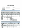
In addition to the requirements mentioned above, the following information should be recorded
by MLI during the monthly well field monitoring events and kept at the landfill:
Name of technician;
ID of each wellhead;
Date/time of each reading;
Velocity head (differential pressure);
Wellhead system integrity and maintenance or repair requirements, including:
o Valves operational
o All monitoring devices/ports operational
o All couplings tight
o All hoses/pipes in good condition
Vault/insulation in good condition;
Evidence of animal burrows; and
Other observations.
The LFG/odor technicians perform the following activities on a routine basis, i.e., on a daily to
weekly basis:2
2
After the temporary permanent capping of Cell 3 is completed, Cells 1 through 3 are temporarily or permanently
capped, the tasks that require daily frequency can be reduced to weekly and the weekly tasks to monthly. Once MLI
demonstrates that the hydrogen sulfide average concentration drops consistently below 500300 ppm for three two
17
Moretown Landfill, Inc.
3.4
Cell 3 Odor Maintenance & Preventative Action Plan
Routine visual inspections of the LFGTE facility and/or flare(s);
Maintenance of vertical LFG extraction wells, to include monitoring of liquid levels in
the wells and pumping accumulated liquid from the well when necessary to improve LFG
extraction; at least monthly the liquid levels will be recorded and if the well has liquid
that is blocking 33% or more of the screen, the evaluation of the well will be performed
as outlined in Section 3.1;
Monitoring of LFG composition and flow (daily if needed) from each extraction point
and adjustment of flow rates as needed to minimize air intrusion into the extraction
system;
SEM of the landfill cover system as required by the facility’s proposed Title V Air
Permit;
LFG extraction well field tuning, including monitoring of gas temperature, oxygen
content, and applied vacuum;
Monthly start-up of the utility flare and/or future enclosed flare, and checks on the blower
equipment;
Cover integrity checks, consisting of observations for excessive erosion and/or lack of
vegetation as required by the facility’s future proposed Title V Air Permit; and
Monitoring for conditions that may indicate the presence of a landfill fire.
Gas Well Maintenance
The GCCS includes vertical LFG extraction wells and horizontal LFG collectors strategically
located to extract LFG generated from the waste mass. Each active gas extraction well is
equipped with a pre-fabricated wellhead consisting of a flow measuring device, flow control
valve, temperature probe, and sampling ports. Occasionally, based on the vertical extraction
well location and waste mass surrounding the well, leachate will accumulate in the well to levels
that effect LFG extraction. Indicators of significant leachate impacts include a lack of vacuum at
the well head, reduced LFG flows, or changes in LFG composition. See Appendix E for more
specific setpoints.
If these indicators are observed by MLI, then the vertical extraction well will be evaluated based
on location, age, well construction, and effectiveness and a conclusion will be reached to either
install a pump to lower leachate levels in the well, or to abandon it and install a new well. This
will occur throughout the life of the landfill to maintain the proper level of odor control.
If a pump is installed, then the leachate will either be pumped into a leachate collection system
cleanout, the condensate forcemain, or into a GCCS header pipe, pending the proximity of
infrastructure to the vertical extraction well. If after the pump has been installed leachate
infiltration into the vertical extraction well exceeds the maximum pumping rate and continues to
be problematic, then the well will be re-evaluated based on operating cost, LFG flow rates, the
consecutive months, these tasks are no longer needed for odor control. However, they may be necessary for landfill
gas closure compliance and will be conducted at whatever frequency required for that program.LFG starts to drop,
these tasks will be extended to monthly, quarterly, or annually. Please note that if the odor baseline increase, the
frequency of these activities could be increased until it was determined that changes in the baseline odor have
stabilized.
18
Moretown Landfill, Inc.
Cell 3 Odor Maintenance & Preventative Action Plan
location of the well within the landfill, and odor control as to whether the well is abandoned or
replaced.
Horizontal collectors that show signs of collapse, watering out, pinching, or low gas flow will be
replaced after an investigation confirms that they are not functioning adequately.
3.5
Flare Maintenance
With respect to flare maintenance, the LFG/Odor technicians perform the following activities,
described in more detail in Appendix E, on a routine basis:
Monthly start-up of back-up flare and checks on the blower equipment. This task will
remain as a monthly start-up requirement, even after the landfill is temporarily or
permanently capped.
Checking the operational status of the blower/flare system including blower/flare control
panel status, and observations related to blower/flare maintenance needs.
Testing the blower/flare controls to confirm the automatic feature functions, such as
automatic restart, auto shut-down valve, auto ignition, etc. and provide routine O&M
visits associated with regular blower/flare maintenance as recommended by the
blower/flare manufacturer.
Checking and making observations on LFG extraction system performance including
conducting regular measurements of LFG composition (methane, carbon dioxide,
oxygen, and balance gas) and system vacuum at the main header inlet to the blower/flare
system.
Conducting regular monitoring and adjustment of gas extraction wells including
measurement of LFG composition (methane, carbon dioxide, oxygen, and balance gas),
well vacuum, LFG flow (if applicable), and LFG temperature at each wellhead.
Providing other routine maintenance of gas collection wells including activities such as
replacement of sample ports, replacement of damaged well hoses, raising of PVC well
risers, and other scheduled routine maintenance tasks which can be accomplished during
routine site visits.
Non-routine scheduled maintenance consists of corrective repair or maintenance work, typically
identified during prior routine site visits, and additional site visits. This work could include
items such as resetting of pipe supports, repair of broken header valves, installation and repair of
lateral lines, equipment overhauls, flame arrestor/demister cleaning, condensate draining, blower
bearing greasing, system diagnostics, etc.
Non-routine unscheduled emergency services include events that require immediate response;
these could include, but not be limited to:
Emergency call-out by operating personnel;
Repair of main header line breaks (resulting in no gas flow to the blower/flare station);
Odor complaints;
Loss of flare ignition;
Significantly reduced flow rate; and
Surging vacuum.
19
Moretown Landfill, Inc.
3.6
Cell 3 Odor Maintenance & Preventative Action Plan
Preventative Maintenance
On a routine basis, the LFG/odor technicians should perform cover integrity checks on the
landfill cover system. Per NSPS regulations (60.755(c)(5)), facilities are to visually monitor
cover integrity on a monthly basis. Although the MLI landfill is not an NSPS facility, these
procedures should be followed at least until the temporary or permanent cap is in place. The
cover integrity check consists of a systematic observation to assess conditions such as erosion,
landfill surface cracks or holes, distressed vegetation, bare spots in the landfill cover system,
visual indications of LFG emissions, and leachate breakouts or seeps. When issues are identified,
MLI staff should take the following corrective actions as necessary:
Placement of additional soil;
Placement of agricultural Lime;
Repair of gas piping;
Repair of the cap geomembrane/cover system;
Replacement of worn kanaflex hoses and clamps;
Replacement of worn fittings;
Use of temporary liner (i.e. geomembrane) and ballast;
Temporary connection of the GCCS to passive vents or cleanouts;
Installing pumps in wells to remove condensate and increase extraction of LFG; or
Installation of horizontal collectors or vertical wells.
The LFG/odor technicians should also monitor the performance of the intermediate cover
through examination of leachate production records and by observations made during the
monthly (minimum frequency) cover integrity checks.
3.7
Pump Maintenance
MLI should review the pumping equipment on a regular basis to determine that it is properly
working and to maintain records of the amount of leachate collected. See Appendix E for more
information on the pump maintenance.
20
Moretown Landfill, Inc.
4.0
Cell 3 Odor Maintenance & Preventative Action Plan
MONITORING & RECORD KEEPING
This section presents the environmental monitoring activities conducted at the landfill to
minimize odors.
4.1
Landfill Liner Monitoring
Monitoring will continue to be performed during the post-closure period to monitor performance
of the landfill liner system. Monitoring will include collection of surface and groundwater
samples from specified locations, and collection and analysis of groundwater samples from
specified water supply sources surrounding the facility. In addition, leachate generated at the
landfill will also be monitored for characterization prior to disposal. The groundwater and
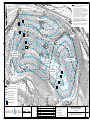
surface water sampling locations included in the facility environmental network are depicted in
the Environmental Monitoring Location Plan found in Appendix F. Lastly, LFG concentrations
are monitored routinely at various site locations.
4.2
H2S Monitoring
The landfill monitors the concentration of H2S on at least a weekly basis at the inlet to the
LFGTE plant initially. The carbon is expected to last a month or moreso, so once a pattern is
established it may be monitored less frequently initially. Air samples are collected in Tedlar
bags and hydrogen sulfide readings are taken with Drager tubes directly from the bag.
H2S levels are currently being reduced to meet air permitting requirements. An activated carbon
rental unit was installed in October 2013. The unit is located after the header systems and before
the blower and before the combustion units. The system is designed to reduce sulfur dioxide
emissions by adsorbing H2S on to activated carbon prior to combustion.
Some form of H2S removal system will be used until the H2S level drops to consistently below
500300 ppm or possibly slightly higher if the LFG flow drops substantially. The current carbon
system was installed as a temporary system. It is a heavy duty system that could remain for as
long as necessary, however a long-term cost evaluation will be completed in 2015the 2014 to
determine the optimal “permanent” system. H2S data will be measured upstream and
downstream of the H2S unit at least weekly as long as the H2S system is operable. This date will
be kept in the facility operating record and submitted to ANR upon request.
As H2S concentrations come down naturally from the older cells and any newer cells apply waste
mixing to minimize odor, it may be possible in a few years to eliminate the H 2S pretreatment
system.
4.3
Stormwater Management Evaluations
Stormwater at the landfill is managed so that it is diverted away from disposal areas. This
minimizes the creation of leachate and allows the water to be managed as stormwater. Finished
slopes are graded, seeded and mulched to promote vegetative growth as soon as possible. The
vegetation holds the soils and minimizes erosion of the landfill areas. The landfill staff inspects
all vegetated areas routinely and maintenance is performed so that the vegetation continues to
prevent erosion.
21
Moretown Landfill, Inc.
Cell 3 Odor Maintenance & Preventative Action Plan
The landfill is required to regularly collect grab samples of stormwater during a rain event and
assess key visual indicators of stormwater pollution which includes odor. If the discharge has a
noticeable odor, for instance if it smells like gasoline fumes, rotten eggs, raw sewage, or solvents
odor, or has a sour smell, this could be indicative of pollutants in the discharge. The findings of
these assessments are used to trigger further facility inspections and corrective action to modify
problems found at the site.
4.4
Leachate Management Plans
The landfill is inspected on an almost daily basis for the seepage of leachate from within the
waste to the slope face as other landfill activities occur. If there is evidence of leachate leaving
the lined area of the landfill, a suitably sized trench should be excavated in the area of the
seepage and backfilled with clean stone to cut off the seepage and direct it to the liner system.
Measures used to minimize leachate production include snow removal and sloping properly
covered refuse in inactive portions of the landfill so that some or all of the runoff is diverted as
uncontaminated stormwater to the perimeter stormwater management system.
MLI is constantly monitoring for seeps. MLI should conduct a systematic seep monitoring
activity on a weekly-to-monthly basis after the temporary permanent capping of Cell 3 is
complete. In the event of a side slope seep, MLI should investigate the cause of the breakout. If
no such cause can be determined, a suitably sized stone filled cut-off trench will be constructed
of necessary length to contain and eliminate the seep.
4.5
Record Keeping
MLI will provide monthly LFG monitoring reports to the DEC until the landfill is temporarily or
permanently capped and afterwards on a quarterly basis.The frequency of reporting will be
outlined in the Post-Closure Certification issued to MLI by ANR.
The contents of these reports and submittal methods are summarized below.
1. The LFG Monitoring Report documents the following monitoring information:
The location of any penetration or grid point that exceeded the 500250 ppm threshold.
Any corrective action taken as a result of the exceedance.
Mapped LFG collection and control system monitoring results for the reporting
month including:
o Maximum LFG temperature at each extraction location;
o Maximum oxygen concentration at each extraction location; and
o Maximum static pressure at each extraction location;
SEM results for the reporting month including:
o The location of any penetration or grid point that exceeded the 500250 ppm
threshold;
o Any corrective action taken as a result of the exceedance; and
o A map of the SEM results that exceed 500250 ppm.
22
Moretown Landfill, Inc.
4.6
Cell 3 Odor Maintenance & Preventative Action Plan
A summary table containing the methane concentrations monitored in each of the onsite structures and the perimeter landfill property gas probes;
Summary of Odor Complaints and responses (See Section 2.8); and
Site plans including the locations of the gas extraction monitoring points and SEM
serpentine path/grid monitoring points.
Emergency Reporting
Any discharge or emission from the facility which poses a threat to public health and safety, a
threat to the environment, or the creation of a nuisance, must be reported within 24 hours to the
Secretary, the local Health Officer, and Select Board of the affected municipality. A written
report should also be submitted to the same parties within 7 days, identifying the discharge or
emission that occurred, the type, quantity and quality of waste, and the actions taken to correct
the problem.
23
Moretown Landfill, Inc.
5.0
Cell 3 Odor Maintenance & Preventative Action Plan
SPECIFIC ODOR CONTROL PROCEDURES
This section presents a number of specific odor control procedures conducted by MLI to
minimize odors at the landfill.
5.1
Odor Control for Breeching the Cap
There is a significant odor potential from any waste or leachate that breaches the cap. The
primary goal is to eliminate the breech as soon as possible. If the breech cannot be addressed
within one business week and the odor potential is drastically increased, MLI will operate a
fogging machine with a counteractant or masking agent to alter the hedonic tone (relative
pleasantness) of the odor, weather permitting. Over a short period of time, pine scent could be
used to mix with the odor to mask the odor character.
5.2
Odor Control for Excavating into Waste
Excavating waste activities should be very limited for the closed cells and especially after the
temporary or permanent caps are is in-place, however, if a need arises to excavated waste to
repair seepage, replace wells, etc, the effect on the odor baseline should be monitored closely.
Daily odor patrols should occur while waste is being excavated.
If unexpected odors are encountered, the most appropriate course of action will be determined
based on the location of the odor. During the initial excavation, particular attention will be given
to determining if there are excessive odors during the excavation operation themselves. If odors
do occur during excavation, contingencies would include:
Grading the cut slope to 3:1 H:V and covering with earthen material;
Use of alternative clean daily cover such as Posi-Shell; and
Limiting excavations to periods of favorable (dry windy) atmospheric conditions.
If odors are encountered during placement of the material, contingencies would include limiting
the amount of stockpiled material to the amount that can be used immediately.
If these odor control contingency plans are not sufficient, additional contingencies, such as use of
chemical odor control agents could also be used, subject to further evaluation of effectiveness.
5.3
Odor Control for Clean Out or Wellhead Replacements Procedures
Clean out or replacement procedures should be scheduled when meteorological conditions are
not still and not drifting towards the west (where residential properties are located). If possible,
neighboring property owners should be contacted so they understand that there may be a
temporary increase in odor. In addition, the landfill should consider operating a fogging machine
with a counteractant or masking agent to alter the hedonic tone (relative pleasantness) of the
odor, weather permitting. Over a short period of time, pine scent could be used to mix with the
odor to mask the objectionable odors.
24
Moretown Landfill, Inc.
5.4
Cell 3 Odor Maintenance & Preventative Action Plan
Odor Control for Replacing Wells
No holes or trenches should be left uncovered or open overnight. In addition, any waste and soil
materials excavated from either a vertical well or trench should be disposed of in the operating
section of the site and covered on a daily basis, or appropriately stockpiled and covered for
disposal offsite. Removal of excavated waste from the drilling area should be a continuous
process, such that when the well installation is complete all the excavated waste has been
removed and appropriately disposed of or stockpiled.
25
Moretown Landfill, Inc.
6.0
Cell 3 Odor Maintenance & Preventative Action Plan
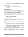
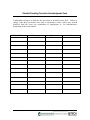
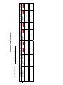
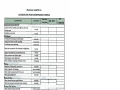
LONG-TERM FINANCIAL COMMITMENT TO ODOR CONTROL
MLI is committed to controlling odors at the landfill. Part of that commitment is providing the
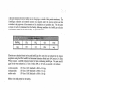
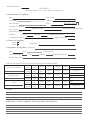
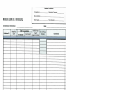
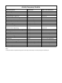
necessary financial resources, as set forth in the following chart:
Post Closure Financial Commitment to Odor Control
Moretown Landfill, Inc.
DESCRIPTION
Groundwater Well Monitoring
QUANTITY
88
UNITS
EA
UNIT COST ($)
$816.00
TOTAL COST ($)
$71,808.00
Groundwater Well Maintenance
1
EA
$1,080.00
$1,080.00
Surface Water Monitoring Point(s)
20
EA
$510.00
$10,200.00
Underdrain Discharge Monitoring Point(s)
4
EA
$816.00
$3,264.00
Leachate Monitoring and Analysis
1
LS
$9,600.00
$9,600.00
Leachate Disposal
1
LS
$29,000.00
$29,000.00
Leachate System Maintenance
1
LS
$2,150.00
$2,150.00
Engineering Inspections
1
EA
$1,800.00
$1,800.00
Mowing
36
AC
$120.00
$4,320.00
Grassing/Landscaping
36
AC
$25.00
$900.00
Access Road Maintenance
100
LF
$42.00
$4,200.00
Slope Failure/Final Cap Repair
1
LS
$30,000.00
$30,000.00
Sediment Basin Cleanout
3
EA
$2,550.00
$7,650.00
Stormwater Ditch Maintenance/Repair
200
LF
$10.20
$2,040.00
2
EA
$2,550.00
$5,100.00
Fencing
200
LF
$28.50
$5,700.00
Gate(s)
1
EA
$1,200.00
$1,200.00
Sign(s)
5
EA
$50.00
$250.00
Independent Construction Manager
1
LS
$2,600.00
$2,600.00
Administration
LFG System Maintenance/Odor
Control
Flare Maintenance
1
LS
$8,000.00
$8,000.00
1
LS
$10,000.00
$10,000.00
Header and Lateral Maintenance
1
LS
$30,000.00
$30,000.00
NSPS Compliance
1
LS
$10,000.00
$10,000.00
Odor Complaint Response Hotline Budget
1
LS
$5,000.00
$5,000.00
Pump Maintenance
1
LS
$5,000.00
$5,000.00
Pump Replacement
1
LS
$5,000.00
$5,000.00
Gas Well Maintenance
1
LS
$5,000.00
$5,000.00
Gas Well Replacement
1
LS
$10,000.00
$10,000.00
Condensate Sampling & Analysis
1
LS
$250.00
$250.00
Third Party Inspections
1
LS
$2,500.00
$2,500.00
Utilities
1
LS
$3,000.00
$3,000.00
Stormwater Structure Maintenance/Repair
ANNUAL POST-CLOSURE COST ESTIMATE
TOTAL POST-CLOSURE COST (30yr)
26
$286,612.00
$8,598,630.00
$8,598,360.00
Moretown Landfill, Inc.
7.0
Cell 3 Odor Maintenance & Preventative Action Plan
HAZARDOUS AIR SAMPLING
Increased landfill odor is typically from sulfur containing compounds that have very low odor
thresholds. Some mercaptan compounds have odor thresholds in the low parts per trillion level.
A part per trillion is very small. For example, in the context of time, a part per trillion would
equate to just one second in 32,000 years. Importantly, if odor is present at detectable levels at
very low concentrations, it does not mean that there is a nuisance or a health concern.
Hazardous air sampling is not a requirement of state law or the Air Permit. However, following
a period of increased odors at the landfill last winter, DEC requested that MLI conduct hazardous
air sampling at the landfill. MLI performed the voluntary sampling in winter and again this past
summer. Even when including very conservative assumptions, no exceedances of state HAAS
thresholds were identified. A memorandum summarizing the study is included in Appendix G.
Based on these results, MLI is not planning on conducting any additional voluntary hazardous air
sampling.
27
APPENDIX A
AIR PERMIT
Appendices
Appendices
APPENDIX B
ODOR PATROL LOG
Appendices
Appendices
The following form is FOR INTERNAL USE ONLY.
Only trained investigators should fill out this form.
MORETOWN LANDFILL ODOR PATROL LOG
Date:
Investigator’s Name:
Starting Time:
Your best estimate of current weather conditions:
Wind Direction (wind coming from the): N
NE E
NW
Condition:
Average Wind Speed:
Low (5-10 mph) High (10+ mph)
Temp (oF):
None/Still
Calm
SE
Weather conditions from www.Weather.com:
S SW W
Weather: Clear Skies Partly Cloudy Cloudy Light Rain Heavy Rain
Snow
Pressure (in.):
Wind from the:
_ Wind speed (mph):
Jerome 631X Hydrogen Sulfide Sampling Results:
Jerome 631X Preparation:
(check each set-up step)
□ 1) Use Zero Air Filter
□ 2) Sample until readings stabilize
#9 =
#1 =
□ 3) Perform sensor regeneration
□ 4) Zero Adjust 30 minutes after regeneration
PPM
#7 =
PPM
#8 =
#3 =
#2 =
PPM
PPM
PPM
#6 =
PPM
PPM
#5 =
#4 =
PPM
PPM
Circle your answers to the questions below:
Did you notice any odor?
Yes
How strong was the odor?
Trace Noticeable
What did it smell like?
No
Highest measured H2S level:
Moderate
Gas (propane/methane) Garbage
Where do you think the odor came from?
Was the Jerome 631X calibrated before use:
Unsure
Yes No
Strong
Very strong
Diesel truck Rotten eggs
Garbage Truck
PPM
Compost
Other
Landfill
Was the User’s Manual Followed: Yes No
REMEMBER TO DOCUMENT ALL READINGS FROM THE ODOR PATROL IN THE ELECTRONIC DATABASE
APPENDIX C
ODOR COMPLAINT RESPONSE FORM
Appendices
Appendices
Odor Response No.:.
APPENDIX C
Moretown Landfill, Inc. -Odor Complaint Response Log
1) Identification of Complaint:
Date:
Caller Name:
Time of call:
Address:
Phone Number:.
Email:
Send Copy Log-,
Location of Complaint:
Impacted: Inside/Outside/Both
Duration of Odor:
Time of Odor:
Description of Odor: _
Humidity:
Weather:_ _ _ _ _Temp.:
Wind Speed/Direction:
.-
Response Required:
Complaint received by:
2) Nature of Complaint:
Odors :
Other :
Description:
3) Complaint Investigation: Responder:
Date:
Contact Person:
Time:
Observed Weather:
Temp.:
Humidity:
Wind Speed/Direction:
Weather Station Data:
Odor Type/Strength based on field investigation compared to butanol standard .
Location of Complaint:
Landfill Property:
Other:
Odor
Type
Odor
Strength
Odor
Type
Odor
Strength
Odor
Type
Landfill
Gas
no
odor
Landfill
Gas
no
odor
Landfill
Gas
Odor
Strength
no
odor
Leachate
Trash
Sludge
Compost
very
faint
faint
moderate
strong
Leachate
Trash
Sludge
Compost
very
faint
faint
moderate
strong
Leachate
Trash
Sludge
Compost
very
faint
faint
moderate
strong
Findings:
4) Response to Odor Complaint (Follow-up I Recommendations)
Other:
very strong
Other:
very strong
Other:
very strong
APPENDIX D
SUFACE EMISSIONS MONITORING PLAN
Appendices
Appendices
SURFACE EMISSIONS MONITORING PLAN
MORETOWN LANDFILL
Moretown, Vermont
PreparedforMoretown Landfill, Inc.
June 2015Feburary 2013
TABLEOFCONTENTS
1.0
INTRODUCTION..............................................................................................................................1
2.0
MONITORINGPLANRATIONALE...........................................................................................1
3.0
SURFACEEMISSIONMONITORINGPROCEDURES.........................................................2
4.0
ACTIONSREQUIREDBYANEXCEEDANCE........................................................................3
5.0
REPORTING......................................................................................................................................3
6.0
PREVENTATIVEMAINTENANCE............................................................................................4
7.0
SEMANDREPORTINGSCHEDULESUMMARY.................................................................54
FIGURES
Figure1–SEMSamplingGridPlan
1.0
INTRODUCTION
The Vermont Department of Environmental Conservation (VTDEC), has requested that the
Moretown Llandfill (ML) operated by Moretown Landfill, Inc. (MLI), located in Moretown,
Vermont, develop a Surface Emissions Monitoring Plan (SEM Plan) detailing procedures for
monitoring surface emissions (i.e. landfill gas [LFG]) from the landfill, and the landfill gas
collection and control system (GCCS). The landfill currently uses a third party consultant
(Consultant) to administer the SEM Plan, including performing the surface scans and completing
the necessary reporting.
MLI is currently not required to monitor the GCCS and cover integrity of the landfill in
accordance with 40 Code of Federal Regulations (C.F.R.) Part 60 Subpart WWW (the New
Source Performance Standards [NSPS] for Municipal Solid Waste [MSW] landfills), and 40
C.F.R. Part 63, Subpart AAAA (the National Emission Standard for Hazardous Air Pollutants
[NESHAPs] for MSW landfills), but this SEM Plan has been prepared based on the requirements
of these regulations. Currently, surface emissions monitoring (SEM) at the Moretown Landfill
(ML) landfill is performed by measuring the fugitive emissions (methane) along a serpentine
path and at cap/cover system penetrations as prescribed by the NSPS. Although, the operational
standard for “fugitive” methane based on the NSPS is 500 parts per million (ppm) above the
“background” concentration, the ML is currently (2013) reporting fugitive emissions greater than
or equal to 50 ppm to the VTDEC. The 50 ppm threshold was implemented by MLI as a
response level to proactively reduce potential odor issues that may result from fugitive emissions
through the landfill’s cover system. Going forward, MLI will document and perform corrective
measures when SEM readings indicate an exceedance of a 250 500 250 ppm methane threshold.
This SEM Plan presents the required SEM procedures to check for fugitive emissions that can be
used as verification that the GCCS is functioning properly. A narrative describing the
monitoring schedule and procedures along with the reporting requirements is included below.
This SEM Plan also provides information on monitoring point locations, steps that will be
followed in the event of an exceedance, and reporting methods and techniques for confirming the
landfill's final cover integrity.
2.0
MONITORING PLAN RATIONALE
The SEM Plan will be implemented to document that the GCCS is operating properly, and that
methane concentrations at ground level within the landfill’s limit of waste containment (LOW)
are below the threshold of 250 500 250 ppm. Therefore, the action level in this SEM Plan is
based on a fugitive emission concentration of 250 500 250 ppm within the landfill’s LOW.
In addition to performing SEM, the Consultant will perform cover integrity checks which include
an inspection of the cover soil for slumps, seeps, distressed vegetation, etc. Observed cover
issues will be repaired as soon as possible by ML landfill personnel or an authorized contractor.
The Consultant will also monitor all above-grade (exposed) piping, wellheads, leachate cleanout
risers, and structures within the permitted LOW.
February AprilJune 201320142015
20130205-Surface Emission Monitoring Plan.docx
Page 2
The ML landfill is composed of one (1) distinct disposal area consisting of four (4) disposal
cells: the Capped Unlined Landfill (closed); Cell 1 (closed); Cell 2 (90% Closed); and Cell 3.
The permitted final topography for the disposal area is generally at a slope of 3 horizontal to 1
vertical. Active landfilling activities are being conducted in Cell 3.MLI is currently seeking
regulatory approvals to place permanent and temporary capping on Cell 3.
The SEM routes are based on a serpentine path with monitoring locations spaced approximately
15-meters (50 ft) apart. Cap and cover system penetrations such as wells and piping, or visuallyobserved slumps, seeps, cracks, or distressed vegetation on slopes will be monitored for fugitive
emissions during the initial monthly SEM event and during each follow-up monitoring event.
The SEM data will be included in the Monthly LFG Monitoring Reports (See Section 5.0).
Refer to attached Figure 1, the SEM Sampling Grid Plan for monitoring route locations at the
MLlandfill.
3.0
SURFACE EMISSION MONITORING PROCEDURES
SEM monitoring will be performed using a flame ionization detector (FID). Prior to beginning
SEM, the Consultant will calibrate the FID in accordance with the manufacturer's instructions.
After the FID has been calibrated, the Consultant will determine the background methane
concentrations by moving the sampling device's probe inlet to upwind and downwind locations
at a minimum distance of at least 50 feet outside the LOW.
At a minimum, MLI will instruct the Consultant to perform monthly SEM of the landfill using an
FID at the following locations:
Along a predetermined serpentine path/grid (see Figure 1);
At each of the cap/cover system penetrations; and
At each of the locations where fugitive emissions were encountered during prior monitoring
events as described in Section 4.0 below.
The Consultant will conduct SEM by holding the FID probe inlet 5 to 10 centimeters (2 to 4
inches) from the ground surface. During the SEM event, the Technician will observe the surface
on either side of the monitoring routes, looking for areas of distressed vegetation, as well as
cracks or seeps in the cover material. Methane concentrations will be measured at any area
indicating distressed vegetation, and the results shall be recorded. Additionally, the Consultant
will observe the integrity of any exposed capping system component.
Any exceedance of the 250 500 250 ppm threshold will be documented, and the SEM data
will be included in the Monthly SEM reports. The SEM reporting requirements are described in
Section
5.0.
In the event that inclement weather (rain or snow) prevents the Consultant from performing
monitoring activities, the monitoring event will be performed as soon as weather conditions
permit.
3040.0
February AprilJune 201320142015
20130205-Surface Emission Monitoring Plan.docx
Page 3
4.0
ACTIONS REQUIRED BY AN EXCEEDANCE
In the event a methane concentration measurement exceeds a concentration of 250 500 250
ppm above the established background, the location shall be tracked and reported. To correct an
exceedance, the following procedures shall be completed:
1.
Cover material shall be evaluated in and around the vicinity of the exceedance, and
repaired if required.
2.
If a point source odor is identified on the landfill’s surface, then Agricultural Lime will
be applied to the source by the landfill personnel or an authorized contractor.
3.
The GCCS vacuum shall be adjusted (increased) in the extraction well heads adjacent to
the exceedance location, if gas quality at these well heads allows.
4.
The location of the exceedance shall be re-monitored within seven (7) calendar days of
detecting the initial exceedance.
a.
If no exceedance is detected the second time, then the location shall be
remonitored again in two (2) weeks from the date of the initial
exceedance. If no further exceedance is detected the third time, then no
further monitoring is required until the next scheduled monitoring event.
b.
If an exceedance is detected the second time, then additional corrective
action (as outlined in Steps 1 through 3 above) shall be performed, and the
location re-monitored within seven (7) calendar days of the second
exceedance.
1)
If no exceedance is detected the third time, then actions described
in Step 4a above shall be taken (i.e., re-monitor in two (2) weeks,
etc.).
2)
If an exceedance is detected the third time, then a new well or
other collection device shall be installed within 120 days of the
first exceedance. An alternate method to remedy the exceedance
may be submitted to the regulatory agency for approval.
5.0
REPORTING
MLI ’s Consultant will provide Monthly LFG monitoring reports on a monthly basis to the
VTDEC. The contents of these reports and submittal methods are summarized below.
1.
Monthly LFG Monitoring Report: The Monthly LFG Monitoring Report documents the
following SEM information:
The level and location of any penetration or grid point that exceeded the 250 500 250
ppm threshold; and
3040.0
February AprilJune 201320142015
20130205-Surface Emission Monitoring Plan.docx
Page 4
Any A summary of corrective actions taken as a result of the exceedance.
Additionally, a map of the SEM results will be prepared by the Consultant on a monthly basis.
The monthly report will include the SEM methane concentration results that exceed 250
500250 ppm at each of the locations indicated above.
6.0
PREVENTATIVE MAINTENANCE
Primary Preventative Maintenance activities will consist of MLI’s staff inspecting the disposal
areas final and intermediate cover for failures (slumps, seeps, distressed vegetation, etc.).
Necessary repairs shall be completed as soon as practical, and recorded in the monitoring logs.
The locations of the failures shall be re-inspected within 10 to 30 calendar days of detecting
the failure and making the necessary repairs.
In addition to monitoring based on the reporting thresholds indicated above, the ML has
also implemented a Preventative Maintenance Monitoring Program, which is based on a
threshold of
50 ppm. During monthly and follow-up SEM events, a methane concentration measurement
greater than 50 ppm above the established background concentration will require MLI’s
LFG/Odor technicians to investigate the area immediately to determine the source of the
emission.
When the direct source of the emission(s) is found, MLI’s LFG/Odor technicians will
provide this information to the Landfill Operations Manager and preventative maintenance
options will be discussed and the appropriate action(s) will be taken.
Preventative
maintenance actions may include, but are not necessarily limited to:
Placement of additional soil;
Placement of Agricultural Lime;
Repair of gas piping;
Repair of the cap geomembrane/cover system;
Replacement of worn kanaflex hoses and clamps;
Replacement of worn fittings;
Use of temporary liner (i.e. geomembrane) and ballast;
Temporary connection of the GCCS to passive vents or cleanouts;
Installing pumps in wells to remove condensate and increase extraction of LFG; or
Installation of horizontal collectors or vertical wells.
3040.0
February AprilJune 201320142015
20130205-Surface Emission Monitoring Plan.docx
Page 5
In addition to the previous preventative maintenance options, gas wells will be monitored to
ensure they are operating as designed. Preventative maintenance of a well with inadequate
“draw” capacity is outlined below.
If a well is exhibiting insufficient draw capacity, the well will be a candidate to be pumped
down with a pneumatic pump if the following conditions occur:
1. More than 50% of the perforated section of the well is submerged or silt has filled the
bottom of the well or both (confirmed by sounding, bubble tube, snake camera, and a
comparison to drill logs);
2. The difference in the available system pressure and static pressure is less than 3 inches
of water column;
3. Either:
a. methane exceeds 55%;
b. or low methane percentage and oxygen exceeds 5%.
If a well has good draw capacity, good flow, can be adjusted to increase pressure to greater
than 3” of water column, has methane in the 45% to 55% range, it should not be pumped even
if it has less than 50% well screen capacity.
Wells will be a candidate for replacement under the following condition:
1. If after evaluation and pumping the well does not return to the range specified above;
2. If the snake camera indicated that the well has a pinched or broken casing or is leaning
too much to install a pump;
3. If well records or snake camera indicate that the well has been raised multiple times
and includes more than 50’ of continuous solid pipe.
7.0
SEM AND REPORTING SCHEDULE SUMMARY
The following is a schedule of the SEM and reporting requirements for the ML:
1.
SEM of Penetrations and Serpentine Path: At least monthly with follow-up monitoring.
2.
Preventative Maintenance: Perform as needed.
3.
SEM Reports: Monthly reports shall be submitted to the VTDEC.
3040.0
FIGURE 1
NSPS SEM SAMPLING GRID PLAN
c 2013 SANBORN, HEAD & ASSOCIATES, INC.
NOTES:
1.
430
U .S. R
OUTE
2
460
CONDENSATE
KNOCKOUT
FLARE
W
3
LFGTE FACILITY
2
4
2
F
53
E
500
1
1
5
6
7
8
9
10
3
4
5
6
7
8
50
52 51
49 48
1
CELL 1 PUMP
W
HOUSE
W
0
W
5
W
2
4
47
46
500
6
7
1
5 4
43
9
6
7
540
10 CELL 1
10
PERMANENT
11
CAPPED
11 AREA
9
55
54
42
53
44
J
52
40
39
1
2
3
38
4
5
10 11
12
13
15 16
14
14
15
16
17
18
18 19
16 17
15
19
21
20
20
22 23
21
17
24
22
25
530
18
23
19
24
25
27
28
26
33
550
37 36
45
44
570
43
32
31
10
20
22
21
26
23
27
28
29
30
31
29
32
31
32
33 34 35
13
24
36
39
40
1D
3
1
4
3
4
0
56
580
LANDFILL CELL LIMITS
5
6
7
SERPENTINE PATH ID
49
0
51
0
16
11
15
14
10
9
7
8
13
8
12
9
10
11
600
620
DRAWN BY: C. RIVET/M. HILDENBRAND
PLOT DATE: 2-5-13
17
12
8
48
0
0
58
SEM SAMPLING GRID
SANBOR N
18
13
9
630
19
14
10
6
5
21
20
15
11
2
3
22
16
12
6
23
0
59
A
24
18
14
CELL 2 PERMANENT
CAPPED
AREA
17
13
9
5
4
25
19
7
2
26
20
16
34
2
56
0
22
21
15
1
B
28
27
23
5
C
29
54
0
7
2
52
0
30
6
1
0
52
31
0
0
55
43
48
0
57
0
540
15
30
53
EXISTING GRAVEL ROAD
EXISTING TREELINE
THE VERTICAL DATUM IS BASED ON THE NAVD OF 1988 AND THE HORIZONTAL DATUM
IS BASED ON THE VERMONT STATE PLANE COORDINATE SYSTEM (NAD 83).
CELL 250PUMP
0
HOUSE
8
29
41
11
60
0
10
12
14
17
27
28
17
16
26
42
0
50
63
0
25
CELL
372
48
TEMPORARY
AREA
49CAPPED38
51
52
23
35
46
19
20
21
18
22
34
45
50
36
31
33
24
28
29
32
25
26
27
30
42
47
34 33 32
36
37
38
40
41
55
EXISTING 2-FOOT CONTOURS
CTB FILE: SHA Standard.ctb
TOPOGRAPHY TAKEN FROM A PLAN ENTITLED "MORE0001-2013
VOLUMES-010213.DWG" PREPARED BY BUTTON PROFESSIONAL LAND SURVEYORS,
PC OF BURLINGTON, VERMONT DATED JANUARY 2, 2013 AND PROVIDED TO
SANBORN HEAD IN DIGITAL FORMAT. CONTOURS REPRESENT SITE CONDITIONS
AT END OF DAY ON JANUARY 2, 2013.
46
0
35
44
34
33
30
31
0
51
53
EXISTING 10-FOOT CONTOURS
LAYOUT: FIGURE 1
C.
2.
54
EXISTING PAVED ROAD
FILE: S:\RANDATA\3000s\3040.03\Graphics Files\CAD\SEM Plan\20130205 - SERPENTINE PATH.dwg
TOPOGRAPHY TAKEN FROM A PLAN ENTITLED "TOP TOPO OF CELL 3" PREPARED
BY GRENIER ENGINEERING, PC OF WATERBURY, VERMONT DATED DECEMBER 7,
2012 AND PROVIDED TO SANBORN HEAD IN DIGITAL FORMAT. CONTOURS
REPRESENT SITE CONDITIONS AT END OF DAY ON DECEMBER 7, 2012.
30
43
35
25
CELL 3C
29
38
36
500
LEGEND
J
B.
26
27
28
39
37
26
24
22
39
29
25
21
41
610
28
24
20
23
42
23
40
540
17
EXISTING TOPOGRAPHY PREPARED USING AERIAL PHOTOGRAMMETRIC
TECHNIQUES FOR MORETOWN LANDFILL, INC. (MLI) BY LAND & MAPPING SERVICES
(L&M) OF CLEARFIELD, PENNSYLVANIA. TOPOGRAPHY WAS DEVELOPED BASED
ON AERIAL PHOTOGRAPHS DATED 11/11/12 AND PROVIDED TO SANBORN HEAD IN
DIGITAL FORMAT AT AN ORIGINAL SCALE OF 1" = 100'.
0
53
520
510
19
30
11
22
32
34 33
35
CELL 3B
9
510
530
18
24
25
27
W
XREFS: S:\CAD Library\AS-BUILTS\MLI\20130102 - MLI Comp Base (ns).dwg
46
26
W
W
17
21
590
34
8
7
13
14
35
47
38
6
CELL 3A
54
36
27
40
48
49
8
9
28
530
39
37
20
29
42
51
12
13
43
50
41
19
510
45
I
3
8
12
56
2
54
0
520
490
8
9
IMAGES:
57
3
7
14
15 16 17 18
UNLINED LANDFILL
490
CAPPED AREA
10 PERMANENT
11 12 13 14 15
16
13
41
H
2
6
W
11 12
540
1 58
G
3
470
520
CELL 3 PUMP
HOUSE
0
48
A.
480
W
W
46
THE BASE MAP WAS DEVELOPED FROM THE FOLLOWING SURVEY DATA MERGED BY
SANBORN, HEAD & ASSOCIATES, INC. (SANBORN HEAD):
HEAD
DESIGNED BY: C. RIVET
GRAPHICAL SCALE
80'
40'
0
80'
REVIEWED BY: J. HANEY
MORETOWN LANDFILL, INC.
MORETOWN LANDFILL
MORETOWN, VERMONT
PROJECT MGR: J. HANEY
160'
PIC: D. ADAMS
NO.
DATE
DESCRIPTION
BY
DATE: FEBRUARY 2013
PROJECT NUMBER:
3040.03
FIGURE NUMBER:
SEM SAMPLING GRID PLAN
1
APPENDIX E
O&M MANUAL FOR LFG AND CONDENSATE MANAGEMENT SYSTEMS
Appendices
Appendices
MORETOWN LANDFILL, INC.
LANDFILL GAS COLLECTION, CONTROL AND
CONDENSATE MANAGEMENT SYSTEMS
STANDARD OPERATING PROCEDURES
Prepared for
Moretown Landfill, Inc.
19 Kaiser Drive
Waterbury, VT 05676
November 2013REV. April 28, 2014
REV. June 11, 2015
TABLE OF CONTENTS
1
REVISION HISTORY ........................................................................................................... 1-1
2
INTRODUCTION ................................................................................................................. 2-1
3
GENERAL INFORMATION ................................................................................................. 3-1
3.1
GCCS DISCUSSION ........................................................................................................ 3-1
3.1.1
Landfill Gas Overview ........................................................................................... 3-1
3.1.2
Landfill Gas Collection and Control System ......................................................... 3-2
3.2
HEALTH AND SAFETY....................................................................................................... 3-3
3.3
GCCS CONTACTS .......................................................................................................... 3-3
4
GCCS OPERATING LIMITS ............................................................................................... 4-1
4.1
GCCS OPERATING LIMITS .............................................................................................. 4-1
4.2
ENERGY FACILITY AND FLARES ........................................................................................ 4-1
4.2.1
Utility Flare ............................................................................................................ 4-1
4.3
APPLIED VACUUM AT CONTROL DEVICES ......................................................................... 4-2
5
GCCS MONITORING EQUIPMENT.................................................................................... 5-1
5.1
W ELLFIELD MONITORING ................................................................................................. 5-1
5.1.1
Calibrating the Analyzer........................................................................................ 5-2
5.2
LIQUID LEVEL MEASUREMENT EQUIPMENT SPECIFICATIONS .............................................. 5-3
5.3
SURFACE EMISSIONS MONITORING EQUIPMENT ............................................................... 5-4
6
GCCS MONITORING AND OPERATION ........................................................................... 6-1
6.1
COMBUSTION PLANT OPERATION ..................................................................................... 6-1
6.1.1
Vacuum Set-Point ................................................................................................. 6-1
6.1.2
System Shutdown ................................................................................................. 6-1
6.2
GCCS MONITORING EVENTS .......................................................................................... 6-1
6.2.1
Flow Rates ............................................................................................................ 6-1
6.2.2
Wellfield Monitoring Schedule and Tuning Frequency ......................................... 6-2
6.2.3
Initial Wellhead Measurements ............................................................................ 6-3
6.2.4
Adjusted Wellhead Measurements ....................................................................... 6-4
6.3
LIQUID LEVEL MEASUREMENT .......................................................................................... 6-4
6.3.1
Measurement Frequency ...................................................................................... 6-4
6.3.2
Liquid Measurement Procedure ........................................................................... 6-4
6.4
SURFACE EMISSIONS MONITORING PROCEDURES ............................................................ 6-4
6.4.1
Surface Emissions Monitoring .............................................................................. 6-5
6.4.2
SEM Weather Conditions ..................................................................................... 6-5
7
DATA MANAGEMENT AND REPORTING ........................................................................ 7-1
7.1
W ELLFIELD DATA MANAGEMENT ...................................................................................... 7-1
7.1.1
Electronic Data (If applicable) .............................................................................. 7-1
7.1.2
Reporting Procedures ........................................................................................... 7-1
7.1.3
Monthly Wellfield Reports ..................................................................................... 7-2
7.2
LIQUID LEVEL DATA MANAGEMENT .................................................................................. 7-2
7.3
SEM REPORT ................................................................................................................. 7-3
i
8
GCCS INSPECTION AND MAINTENANCE ....................................................................... 8-1
8.1
COMPONENT INTEGRITY CHECKS ..................................................................................... 8-1
8.2
W ELLHEAD INSPECTION AND MAINTENANCE ..................................................................... 8-1
8.2.1
Inspect and Maintain............................................................................................. 8-1
8.2.2
Document and Repair ........................................................................................... 8-1
8.2.3
Inspection Frequency ........................................................................................... 8-1
8.2.4
Joints..................................................................................................................... 8-2
8.2.5
Valves ................................................................................................................... 8-2
8.2.6
Sample Ports ........................................................................................................ 8-2
8.2.7
Flex Hose .............................................................................................................. 8-2
8.3
PUMP INSPECTION AND MAINTENANCE ............................................................................. 8-3
8.4
W ELL AND SURROUNDING AREA INSPECTION AND MAINTENANCE ...................................... 8-3
8.4.1
Well Casing........................................................................................................... 8-3
8.4.2
Surrounding Area.................................................................................................. 8-4
8.4.3
Report Findings .................................................................................................... 8-4
8.5
FLARE INSPECTION AND MAINTENANCE ............................................................................ 8-4
8.5.1
System Operation ................................................................................................. 8-4
8.5.2
Blower Bearing Temperature................................................................................ 8-4
8.5.3
Blower / Motor ....................................................................................................... 8-5
8.5.4
Belts (Belt Drive units, Where Applicable) ............................................................ 8-5
8.5.5
Flexible Couplers (Direct Drive Units, Where Applicable) .................................... 8-5
8.5.6
Blower / Motor Safety Devices ............................................................................. 8-5
8.6
CONTROL DEVICE INSPECTION AND MAINTENANCE ........................................................... 8-6
8.6.1
System Operation ................................................................................................. 8-6
8.6.2
Control Panel ........................................................................................................ 8-6
8.6.3
Flame Arrestor ...................................................................................................... 8-7
8.6.4
Thermocouples ..................................................................................................... 8-7
8.6.5
Valves ................................................................................................................... 8-7
8.6.6
Pilot System .......................................................................................................... 8-7
8.6.7
Flow Meter ............................................................................................................ 8-7
8.7
SPARE PARTS ................................................................................................................. 8-8
8.7.1
Control System ..................................................................................................... 8-8
8.7.2
Collection System ................................................................................................. 8-8
8.8
CONDENSATE MANAGEMENT SYSTEM INSPECTION AND MAINTENANCE .............................. 8-9
8.8.1
Condensate Overview .......................................................................................... 8-9
8.8.2
Condensate Management System ....................................................................... 8-9
8.8.3
Monitoring Requirements.................................................................................... 8-10
8.8.3.1
Condensate Pump Stations ........................................................................ 8-10
8.8.3.2
Knock – Out Pot (KOP)............................................................................... 8-10
8.8.3.3
KOP Demister PAD .................................................................................... 8-10
8.8.3.4
Exercise All Valves ..................................................................................... 8-11
8.8.4
Maintenance Requirements ................................................................................ 8-11
8.8.5
Condensate Sampling & Analysis ...................................................................... 8-12
8.8.6
Record Keeping & Reporting .............................................................................. 8-12
8.9
CONTINUOUS MONITORING EQUIPMENT INSPECTION AND MAINTENANCE ......................... 8-13
8.9.1
Combustible Gas Monitoring System ................................................................. 8-13
8.10 MAIN COLLECTION PIPING INSPECTION AND MAINTENANCE ............................................. 8-14
8.10.1 Sample Points..................................................................................................... 8-14
8.10.2 Valves ................................................................................................................. 8-14
8.10.3 Access Points ..................................................................................................... 8-14
9
SUBSURFACE OXIDATION (SSO-POTENTIAL LANDFILL FIRES)................................ 9-1
ii
9.1.1
9.1.2
9.1.3
9.1.4
9.1.5
9.1.6
9.1.7
9.1.8
10
Symptoms ............................................................................................................. 9-1
Notifications .......................................................................................................... 9-1
Initial Investigation ................................................................................................ 9-1
Data Analysis ........................................................................................................ 9-3
Removing the Oxygen from the Fire..................................................................... 9-3
Things to Avoid ..................................................................................................... 9-4
Continued Monitoring............................................................................................ 9-4
Timeline ................................................................................................................ 9-5
HYDROGEN SULFIDE ...................................................................................................... 10-1
10.1 H2S SAMPLING STANDARD OPERATING PROCEDURE ...................................................... 10-2
10.1.1 Equipment List .................................................................................................... 10-2
10.1.2 Monitoring Strategy............................................................................................. 10-2
11
GREENHOUSE GAS REPORTING RULE ............................................................................ 1
LIMITATIONS
STANDARD OPERATING PROCEDURE ACKNOWLEDGMENT FORM
APPENDICES
APPENDIX A EQUIPMENT SPECIFICATION FORMS
APPENDIX B ANALYZER CALIBRATION FORMS
APPENDIX C SURFACE EMISSIONS MONITORING FORMS
APPENDIX D STARTUP, SHUTDOWN, MALFUNCTION FORM
APPENDIX E WELL ASSESSMENT AND CONDITION REPORT FORM
APPENDIX F FLARE FORMS
APPENDIX G LIQUID LEVEL MEASUREMENT FORM
APPENDIX H COVER INTEGRITY FORM
APPENDIX I VIRIDIAN PUMP MAINTENANCE FORM
APPENDIX J GCCS MAINTENANCE CALENDAR
APPENDIX K HYDROGEN SULFIDE FORM
APPENDIX L GREENHOUSE GAS WEEKLY FORM
iii
1 REVISION HISTORY
Add the effective date of the most-recent revision to the list below. Do not overwrite or
delete any dates. This is intended to be a complete record of all revisions made to this
Landfill Gas (“LFG”) Collection, Control and Condensate Management Systems
Standard Operating Procedures (“SOP”).
Date of Initial Issuance
November 15, 2013
April 28, 2014
Revision Dates
June 11, 2015
1-1
2 INTRODUCTION
This document presents the SOP and minimum operation and maintenance (“O&M”)
efforts required of those parties responsible for performing Gas Collection and Control
System (“GCCS”) and condensate management services for Moretown Landfill, Inc.
(“MLI”) at its landfill in Moretown, Vermont (“Facility”). The location of the landfill is
shown in Figure 2-1.
Specifically, this document describes the procedures and minimum requirements for:
Monitoring, inspection, and maintenance of LFG collection system components;
Monitoring, inspection, and maintenance of LFG control devices;
Monitoring, inspection, and maintenance of condensate systems; and
Data management.
2-1
SITE LOCATION
N
Based on USGS topographic map for Middlesex, Vermont Quadrangle
Figure 2-1.
Site Locus
Moretown Landfill, Inc.
Moretown, Vermont
Not to Scale
3 GENERAL INFORMATION
3.1 GCCS Discussion
The landfill has an LFG gas to energy (“LFGTE”) facility, which is currently operated by
PPL Renewable Energy (“PPL”). The LFGTE facility consists of two existing
Caterpillar G3520C LE LFG-fired internal combustion engine generators. Any excess
LFG collected and not combusted in the engines, as well as generated during periods of
the engines may be off-line, is combusted by an on-site flare.
The purpose of this section is to provide a summary of available information regarding
current LFG management conditions at the landfill, and to provide an outline of the
strategy and actions being taken to manage LFG emissions generated by the historic
landfilling of waste. This section addresses management of LFG at the landfill up to and
including and treatment technologies of LFG.
3.1.1 Landfill Gas Overview
Landfills produce gas as organic materials decompose under anaerobic conditions.
Anaerobic conditions occur when oxygen present in the voids of refuse placed at a
landfill is consumed by aerobes (micro-organisms which consume air to grow), leaving
an environment that is free of oxygen. The LFG generation rate is affected by many
factors including refuse composition, the waste age and quantity, condition of the waste
mass, moisture content, pH, temperature, and maintenance of an anaerobic environment.
Solid waste landfills are capable of generating LFG for many years, with sources such as
the United States Environmental Protections Agency (“EPA”) citing a 20 to 30 year or
longer life for generation of LFG.
LFG contains approximately equal parts of methane and carbon dioxide by volume.
Other gases such as volatile organic compounds and hydrogen sulfide may also be
present in LFG in trace concentrations. Methane is a colorless, odorless gas that is
explosive in concentrations ranging from 5% to 15% in air. At concentrations above
15% methane is flammable. LFG has its own characteristic odor due to the presence of
trace compounds. Some of the more significant odor causing classes of trace constitutes
include ethers, phenols, organic acids, solvents and sulfur compounds.
Once generated, LFG will move through refuse and solid in a landfill disposal area site
by both convection and diffusion. Convection is the movement of gas from an area of
higher pressure to an area of lower pressure. Diffusion is the movement of gas from an
area of higher concentrations to an area of lower concentrations. The emission and
3-1
migration of LFG may potentially have adverse effects on the environment including fire
and explosion, health risk, odor nuisance, vegetative distress, and groundwater
contamination.
3.1.2 Landfill Gas Collection and Control System
LFG generated at the landfill is extracted and destructed using a GCCS. The GCCS is
maintained and operated to minimize fugitive emissions from the landfill that may cause
LFG odors. LFG extraction wells and horizontal collection trenches are strategically
located to collect LFG generated from the waste mass. LFG is also collected from the
leachate collection system at multiple cleanouts at which vacuum is applied. The
collected LFG (from vertical and horizontal LFG collectors and from the leachate
collection system) is conveyed through a series of lateral and header pipe to control
devices; including LFGTE engines, and a utility flare, and a future proposed enclosed
flare.
Each active LFG extraction point is equipped with a pre-fabricated wellhead consisting of
a flow measuring device, flow control valve, temperature probe, and sampling ports.
LFG control valves are installed to isolate and adjust flow in sections of the gas header
pipes. Occasionally, based on the vertical extraction well location and waste mass
surrounding the well, leachate will accumulate in the well to levels that effect LFG
extraction. Indicators of significant leachate impacts include a lack of vacuum at the well
head, reduced LFG flows, or changes in LFG composition. If these indicators are
observed, MLI will evaluate the vertical extraction well based on location, age, well
construction, and effectiveness and determine whether to either install a pump to lower
leachate levels in the well, or to abandon it and install a new well.
If MLI chooses to install a new pump, then the leachate will either be pumped into a
leachate collection system cleanout or into a GCCS header pipe, pending the proximity of
infrastructure to the vertical extraction well. If, after the pump has been installed,
leachate infiltration into the vertical extraction well exceeds the maximum pumping rate
and continues to be problematic, then the well will again be evaluated based on operating
cost, LFG flow rates, the location of the well within the landfill, and odor control as to
whether the well is to be abandoned or replaced.
Gas header pipes ranging from 4- to 18-inch-diameter high-density polyethylene
(“HDPE”) pipe to convey LFG from the extraction source (vertical well or horizontal
collector) to either the LFGTE facility or flares for destruction. The existing LFG
collection headers within the landfill are installed to provide positive drainage to allow
condensate, which has formed during LFG collection, to flow to condensate traps or to a
condensate knockout pot.
Condensate traps and knockout structures are to remove condensate generated in the
GCCS and convey condensate to the leachate collection system for disposal. The
3-2
condensate is pumped from the knockout pot by a submersible pump to the leachate
collection tanks.
3.2 Health and Safety
All parties must comply with MLI’s Health and Safety requirements. Please refer MLI’s
Health and Safety Plan (“HASP”).
3.3 GCCS Contacts
The following are the contact names and numbers for MLI:
Name/Title
William Kernan, Ops. Manager
Office Phone Number
(802) 244-1100 x227
3-3
Cell Phone Number
(802) 279-1315
4 GCCS OPERATING LIMITS
4.1 GCCS Operating Limits
MLI has established the following operating limits for the GCCS, which are identical to
the new source performance standard (“NSPS”) limits:
Wellhead
Parameter
Methane (%)
Oxygen (%)
Applied Vacuum
(in. W.C.)
Gas Temperature
(deg F)
Limit
N/A
up to 5%
up to <0 in. W.C.
up to 131 deg F
4.2 Energy Facility and Flares
Currently an LFGTE facility (which consists of two Caterpillar G3520C LE LFG fired
internal combustion engines) and a utility flare are the primary methods for destroying
LFG at MLI. The LFGTE facility and engines at the landfill are owned, operated, and
maintained by PPL. PPL may seek a permit for a third engine for the LFGTE facility.
MLI retains ownership and maintenance responsibilities for the GCCS, and the existing
utility flare. As part of the Cell 4 Certification, MLI also intends to construct and operate
an enclosed flare.
The existing utility flare is generally operated simultaneously with the LFGTE facility to
combust excess LFG not used by the engines. Any excess LFG collected and not
combusted in the engines, as well as generated during periods when the engines may be
off-line, is combusted by the utility flare. The future enclosed flare will generally be
used to combust higher LFG flow rates when the LFGTE facility is off-line. The goal of
the combined LFGTE engine and flare systems is to achieve 98% destruction efficiency
of total hydrocarbons. A hydrogen sulfide removal system is installed to control the
emissions of sulfur dioxide which is created with the combustion of hydrogen sulfide
entrained in LFG.
4.2.1 Utility Flare
The utility flare assembly consists of the flame arrestor near the base of the flare, vertical
piping to the flame cup, spark sources mounted to the vertical piping, spark leads, spark
4-1
plugs, a thermocouple, and guy wires. The system is started with a manually operated
propane pilot. The flame arrestor prevents the flame from traveling back through the
system in the event of a pressure loss. The vertical piping transmits the gas to the flame
cup.
The open flare assembly is monitored on a monthly basis for the following parameters:
General conditions;
Condition of ignitor system;
Nitrogen supply for control valves;
Propane supply for ignition system; and
Back pressure at flame arrestor.
4.2.2 Enclosed Flare
The proposed enclosed flare will be equipped with temperature sensors and air dampers
to control the ratio of combustion air and LFG and to maintain stable combustion
conditions. Pilot burners assure that the main flare ignites upon electronic ignition startup. The flame arrestor prevents the flame from traveling back through the system in the
event of a pressure loss. LFG is transmitted to the enclosed flare via stainless steel piping
to the base of the flare and is introduced to the stack in a manifold which distributes LFG
evenly within the stack where combustion takes place.
The enclosed flare assembly shall be monitored on a monthly basis, at a minimum, for
the following parameters:
General conditions;
Condition of ignitor system;
Nitrogen supply for control valves;
Propane supply for ignition system; and
Back pressure at flame arrestor.
4.3 Applied Vacuum at Control Devices
The pressure of the LFG will vary throughout the system at any given time, and will also
vary with varying extraction rates. The pressures at the extraction points should be
negative (vacuum) to provide active extraction from that point. If the pressure is positive,
adjustments should be made to increase the flow rate provided the gas constituent
concentrations are within the normal ranges as discussed above.
The vacuum set-point is an important part of maintaining the overall "health" of the
wellfield. Vacuum should be maintained as low as possible while ensuring acceptable
negative pressure is available to the furthest points of the collection system.
4-2
1. Provide GCCS extraction consistency – The vacuum needs to be maintained
consistently so balancing and tuning events are consistent.
2. Prevent excessive air from entering the landfill – Over-pulling on a well can cause
damage to the anaerobic bacterial populations. It may also cause subsurface
oxidation (“SSO”).
3. Prevent under-pulling on wells – Under-pulling on wells does not allow the
GCCS to capture all the gas being generated by the landfill. Under-pulling can
result in surface emissions, odors, and off-site gas migration.
4. Minimize electricity use related to generating vacuum – Blowers use a significant
amount of electricity. Reducing vacuum to minimum acceptable level minimizes
electricity use and reduces electrical surges which may shutdown the control
devices.
4-3
5 GCCS MONITORING EQUIPMENT
It is important to have a complete and accurate set of data collected from the field. The
accuracy and dependability of the monitoring equipment used in the field is key to
providing O&M Personnel with reliable results on which to base tuning decisions.
5.1 Wellfield Monitoring
MLI will utilize a LANDTEC GEM2NAV Gas Analyzer (Analyzer) (Refer to Appendix
A for equipment specifications) or equivalent to monitor the wellfield at MLI. The
monitoring equipment should be set up as follows:
Confirm monitoring point designations. Each monitoring location should have a
site-specific ID, and that the ID is unique to that monitoring point and is
consistent with site's GCCS Drawings, and configured in the monitoring device to
accurately calculate well flows by recognizing the type and size of wellhead, and
the flow measuring device. Alternative wellhead configurations may be used with
approval of MLI.
Compile all site-specific monitoring location ID's into a single ID Set.
Use ID set for all work related to that site.
If a monitoring point is replaced (redrilled), establish a new ID for the
replacement point after the old ID to indicate redrilled/replaced. Do not re-use the
exact old ID for the replaced point.
When creating a new well in the Analyzer, it must be GPS marked.
Suggested comments for valve adjustments are as follows:
o No Change
o Opened Valve ¼ turn, ½ turn, 1 turn, etc.
o Valve Fully Opened
o Closed Valve ¼ turn, ½ turn, 1 turn, etc.
o Valve Fully closed
o Second reading
Suggested comments for operational issues are as follows:
o Surging in Header
5-1
o
o
o
o
o
o
Bad Sample Ports
Valve needs replacement/repair
Flex hose needs replacement/repair
Header vacuum loss
Well bore seal needs replacement/repair
Well needs to be raised/lowered
5.1.1 Calibrating the Analyzer
The monitoring equipment should be calibrated several times during the day of wellfield
monitoring. Use the following steps for field calibration:
1. Inspect in-line filters (water trap and/or carbon filter) for moisture, fine particles,
or breakthrough. Replace the filters if deemed necessary.
2. Inspect the integrity of the sampling apparatus:
a. Sample tubing (Tygon® or equivalent) should seal tight onto the hose
barbs.
b. Note condition of the tubing. Replace the tubing if dirt or moisture has
accumulated.
c. Note sample fitting O-ring(s) condition. Replace the O-rings if deemed
necessary.
3. Perform field calibrations per manufacturer's specifications.
Manual for instructions to calibrate the Analyzer.
Refer to Users
4. Field calibrate the meter:
a. Calibrate a minimum of daily during monitoring events, and
b. If extreme temperature changes and/or atmospheric changes occur during
the monitoring event, perform additional calibrations as necessary.
5. Perform additional field calibrations if the following circumstances occur:
a. Extreme ambient air temperature changes (plus or minus 20 degrees F).
b. Significant increase or decrease in atmospheric pressures.
c. Unable to stabilize gas quality.
d. Erroneous measurements on meter screen (i.e. <<>>).
e. Gas qualities totaling more than 100% volume.
f. Methane concentrations higher than 70% by volume.
g. Oxygen concentrations in ambient air less than 19% or greater than 21%
by volume.
h. Balance gas concentrations in ambient air greater than 81 % by volume.
i. Balance gas to oxygen ratio is less than 4:1 in any gas sample.
5-2
i.
This ratio is based on the fact that ambient air is comprised of
approximately 80% nitrogen and 20% oxygen (a 4:1 ratio). Since
balance gas usually represents mostly nitrogen, and is inert, and
cannot be consumed by landfill bacteria, it is theoretically
impossible to have a ratio less than 4:1 unless something in the
landfill is producing oxygen or consuming nitrogen.
a. Example: a gas sample from a wellhead indicates 6% balance
gas and 2% oxygen. This sample shows a 3:1 ratio indicating
that the internal sensors may need to be recalibrated.
b. Ratios greater than 4:1 are possible and may indicate a
subsurface situation that needs to be immediately addressed.
(Example: a gas sample shows balance gas is 25% and
oxygen is 0.5% - a 50:1 ratio). The example presented
indicates that something in the landfill is consuming the
oxygen that should be present (8%) and the remainder is
balance gas (nitrogen). This example could occur if a
subsurface oxidation (SSO) event is taking place within the
waste mass - the SSO is consuming the oxygen and the inert
nitrogen remains, thus showing a 50:1 ratio.
6. Complete the calibration forms located in Appendix B.
7. Ensure the date and times on the Analyzer are accurate before starting the
monitoring event.
8. Use the appropriate calibration gas for the monitoring event – 50% Methane /
35% Carbon Dioxide / 4% Oxygen, or similar, for monitoring the GCCS.
9. Zero the meter pressure sensors (transducers) during each calibration event.
a. Minimize the impact of wind by cupping hoses in the palm of the hand
(Do not block hose ends).
b. Calibrate pressure sensors and record results on the calibration form.
c. Zero sensors before each wellhead reading if sensors read anything
other than 0.00 when disconnected from the wellhead and are not
impacted by wind.
5.2 Liquid Level Measurement Equipment Specifications
Select vertical gas wells are equipped with ATZ Applied Technologies’, or equivalent,
down-well bubbler system with the hand-held Precision Level Reader to monitor liquid
levels. At the selected gas wells, a drop tube is permanently inserted either through the
well cap or through the side of the well down the well to a known depth. Using the drop
tube, the liquid levels are measured with the use of a micro-compressor and a differential
pressure sensor (e.g., the handheld Precision Level Reader).
5-3
5.3 Surface Emissions Monitoring Equipment
For Surface emission monitoring (“SEM”), MLI will use a Flame Ionization Detector
(“FID”) (Trimble SiteFID™ or equivalent) meeting the requirements of 40 C.F.R. Part 60
Appendix A, Method 21. A Photo Ionization Detector (“PID”) cannot be used for SEM.
MLI should calibrate the meter daily prior to each monitoring event according to
requirements of 40 C.F.R. Part 60 Appendix A, Method 21. Calibration consists of a
three-part procedure:
Instrument calibration to methane standard;
Equipment response time test; and
Calibration precision test.
In addition, the calibration should also include the following:
Determine ambient air background levels prior to performing SEM; and
Must be able to GPS while performing SEM (exceptions will be made only when
there is equipment failure).
Refer to Appendix C for calibration forms.
5-4
6 GCCS MONITORING AND OPERATION
6.1 Combustion Plant Operation
6.1.1 Vacuum Set-Point
The engine plant is operated by PPL and excess LFG not used in the plant is sent to the
flare. The engine plant blower will be operated and maintained to provide a consistent
vacuum on the wellfield. MLI should make the necessary adjustments to the wellfield
and the blower to maintain the set-point during and after wellfield monitoring and tuning.
MLI should also document all adjustments and periodically verify that the vacuum at the
combustion plant is being adjusted appropriately to maintain the set-point.
6.1.2 System Shutdown
If the engines are down for four hours or more, the PPL operator will notify immediately
MLI. MLI’s GCCS operator should start the flare back-up blower and adjust vacuum to
set-point. MLI should continue to monitor the wellfield once vacuum has stabilized from
the back-up blower.
6.2 GCCS Monitoring Events
Valid wellfield data is critical to maintaining compliance and is essential to making
accurate tuning decisions. Without accurate data, improper tuning adjustments can occur
leading to odor and migration issues and potentially long term damage to the gas
producing bacteria population.
The gas extraction flow rates will be different at each extraction point and will vary with
changes in atmospheric pressure as well as landfill cover condition (i.e., geomembrane
cap or intermediate cover). Likewise, the cumulative extraction rate at the blower(s) will
vary with time. The flow rates should be adjusted based on the concentrations of the
various constituents as described above. As the operating record of the system becomes
established over time, "normal" flow ranges for the individual extraction points as well as
the system will become established.
6.2.1 Flow Rates
There are three types of wells to be monitored. The first are perimeter gas probes and are
not included in the well tuning.
Perimeter Gas Probes
6-1
LFG should be monitored with a combustible gas meter. The presence of combustible
gas shall not exceed 25% of the lower explosive limit (“LEL”) in the LFGTE structures,
and shall not exceed the LEL for methane at the property boundary. In the event that the
LEL is exceeded at the property boundary, MLI should immediately take steps necessary
to protect human health.
Horizontal Collection Trenches
The horizontal collection trenches typically consist of perforated, HDPE pipe installed in
trenches excavated in the refuse. The lateral collection trenches are connected to LFG
transmission piping.
The extraction of LFG from the lateral collection trenches is
controlled at a wellhead.
Landfill Gas Extraction Wells
LFG extraction wells, constructed of 8-inch diameter schedule 80 PVC pipe, have been
installed in boreholes drilled with a 30-inch diameter (typical) bucket auger to various
depths within the refuse. Typically, the wells are slotted from depths of approximately
15 feet below intermediate cover grades to the base of the well (which are drilled to
depths within approximately 15 feet of the landfill base liner). The slotted sections of the
wells are backfilled with crushed stone.
6.2.2 Wellfield Monitoring Schedule and Tuning Frequency
The adjustment or "tuning" of the LFG extraction system involves monitoring various
parameters and making adjustments to optimize the extraction of LFG from each
extraction point in the system. The objective of the tuning is to provide for a negative
pressure at each extraction point without causing the intrusion of air into the landfill.
Tuning is an iterative process, as adjustments to any portion of the system have the
potential to affect the entire system. A discussion of the monitoring and tuning
procedures is provided below.
The ultimate goals of balancing and tuning a wellfield are to: 1) maintain the wellfield in
compliance with federal, state and local regulations; 2) maintain compliance with the
facility’s permit; 3) control odors; and 4) control lateral migration and fugitive surface
emissions of LFG. The following balancing and tuning protocols have been developed to
achieve these goals. MLI is currently not subject to the monitoring, recordkeeping, and
reporting requirements of NSPS. Even though MLI is a non-NSPS site, MLI will
implement the following:
Monitor and tune the wellfield at least once per month.
Before beginning of the monitoring and tuning event, verify that the collection
system is operating at under normal conditions (e.g., confirm that conditions such
6-2
as blower maintenance are not occurring or are not scheduled to occur during the
tuning event). If the system is not operating under normal conditions, then
reschedule the monitoring event.
6.2.3 Initial Wellhead Measurements
The following steps are for existing monitoring points. Any new monitoring point needs
to follow the new wellfield procedures.
Make no wellhead adjustments during the initial reading. Save one full line of data
and note in the comments section what action will be completed prior to adjusting
the wellhead and taking the adjusted reading.
Acquire valid wellhead measurements.
o Select appropriate well ID on meter.
o With the sample train and pressure sensor hoses disconnected, activate the
meter's internal sample pump so that the entire sample train is purged and
the results are indicative of ambient air (approximately 20% to 21%
oxygen and 79% to 80% balance gas).
o Perform transducer zero function to ambient air conditions. Be sure to
minimize wind effects during the procedure by shielding the hose ends
(Do not block hose ends.).
o Check wellhead sample fittings for cracks, bad o-rings and blockage by
liquid, ice, spider webs or other substances.
o Record temperature by inserting temperature probe into wellhead
temperature sample port.
Connect all applicable sample train hoses. Verify that all connections are snug
and air tight and verify sample train hoses are not pinched or kinked.
Acquire gas concentrations and differential pressure. Activate sample pump
(should pump for a minimum for 100 seconds while taking sample) and allow gas
measurements to stabilize prior to storing measurements.
Store measurements. Save one full line of data and note in the comments section
what action will be completed prior to the adjusted reading.
Determine if adjusted wellhead readings are necessary (See Table presented in
Section 4.1).
o Review initial wellhead measurements and verify that they are within the
compliance guidelines and the operational limits as defined in Section 4.1.
o If the initial measurements are out of compliance with MLI’s operating
limits in Section 4.2 or other permit requirements, make an adjustment
following the adjustment guidelines listed below and adhere to the
6-3
monitoring procedures listed in the following sections for 5-day corrective
action documenting events and 15-day recheck events.
6.2.4 Adjusted Wellhead Measurements
If an adjustment to the extraction well is required (refer to Section 3.1):
Wait for the Analyzer to come to a steady state.
Limit vacuum or flow change to approximately 10% increase or decrease from
current reading, unless the well is in a known area of SSO or C&D fines, or the
parameters listed in Section 3.1 are exceeded.
Once the adjustment has stabilized, store reading with one of the suggested
comments listed in Section 5.1. Supplemental comments may be included/added
as warranted.
6.3 Liquid Level Measurement
A major limitation to LFG extraction is the presence of liquids within a collection well.
Liquid renders the submerged portion of the screened interval of a LFG well useless.
Controlling liquid buildup in LFG wells is the first step in effective gas management.
6.3.1 Measurement Frequency
Monitor liquid levels in select GCCS wells at least monthly.
6.3.2 Liquid Measurement Procedure
Similar to the procedure for monitoring gas concentrations and flowrates at gas wells, the
ATZ Applied Technologies’ Precision Level Reader system, or equivalent, is used to
record liquid levels by walking up to the wellhead, connecting the system to the sampling
ports, and recording the liquid levels. With the Precision Level Reader system, it is not
necessary to remove wellheads to measure liquid levels. As a result, the potential for
fugitive air emissions that would otherwise occur when measuring liquid levels in gas
wells with conventional water level meters is reduced.
6.4 Surface Emissions Monitoring Procedures
SEM will be performed on a monthly basis, unless a different frequency is otherwise
required. These scans are intended to identify and quantify fugitive LFG emissions, but
also act as a GCCS performance test allowing MLI to analyze areas of the collection
system that may require upgrades or modifications to control surface emissions.
6-4
6.4.1 Surface Emissions Monitoring
Use the following procedures during the SEM event:
Perform SEM in accordance with NSPS protocols documented in 40 C.F.R. §§
60.755(c)(1) to 60.755(c)(4).
Mark FID measurements that are above 500250 ppm background levels
(an exceedance) on the monitoring plan, and place a high-visibility field flag at
exceedance location so location can be identified for future repairs by Facility
personnel.
Odors can occur from very low emission rates of LFG. Thus, MLI has adopted a
Preventative Maintenance Program based on a methane concentration of 50 ppm.
During weekly and monthly monitoring events, if MLI identifies a methane
concentration measurement in excess of 50 ppm above an established
background, the technician will investigate the area to determine the source of the
emission.
Record brief description of exceedance area on the Daily SEM Log Sheet.
6.4.2 SEM Weather Conditions
Perform SEM during ''typical meteorological conditions" per 40 C.F.R. §
60.755(c)(3).
Use an on-site meteorological station during monitoring events to confirm wind
speed.
If the on-site meteorological station is not available, use a weather data service
such as Weather Underground (www.wunderground.com).
6-5
7 DATA MANAGEMENT AND REPORTING
7.1 Wellfield Data Management
Proper management of field data is critically important.
Manipulation or
misrepresentation of field data is a violation of the Clean Air Act and will not be tolerated
by MLI and will be grounds for termination.
Upon downloading data from the meter, use the following procedures to manage the
electronic and written field information.
7.1.1 Electronic Data (If applicable)
DO NOT ALTER THE RAW DATA FILE.
When naming the raw data file (meter download file), use the site name, date of
the event, and technician's initials. Examples:
o MLI tuned on February 7, 2012 by Joe Shanaynay = MLI020712JS.csv,
Download the electronic data and e-mail to the Operations Manager, within 24
hours of completing the monitoring event, defined as one complete round of
monitoring at each collection point at the facility.
Retain copies of unaltered data files.
All data files are the property of MLI. Copies of the files must be provided to
MLI.
If all of the data from a monitoring event is corrupted, lost, or is unusable,
immediately re-monitor the entire wellfield.
If data from certain wells is corrupted, lost, or is unusable, immediately remonitor
those wells.
7.1.2 Reporting Procedures
Reports generated as part of this work are to be submitted to MLI personnel only, unless
otherwise directed by MLI. These records will be retained by MLI at the Facility.
7-1
7.1.3 Monthly Wellfield Reports
Prepare a monthly wellfield report.1 Include the following, at a minimum:
1. Mapped LFG collection and control system monitoring results for the month,
including:
Maximum LFG temperature at each extraction location;
Maximum oxygen concentration at each extraction location; and
Maximum static pressure at each extraction location.
2. Summary of Landfill Cover and GCCS improvements, which includes a summary
of the recommended improvements to the cover system and GCCS.
3. Summary of Landfill Monitoring Activities, which includes a summary of the
landfill monitoring performed by MLI.
4. A monthly summary table containing the methane concentrations monitored in the
on-site structures and perimeter gas probes.
5. Odor Response Summary Table, which includes a monthly summary of responses
to each odor complaint and a description of measures taken to resolve the odor as
performed by MLI.
7.2 Liquid Level Data Management
Maintain historical information in a liquid level log electronic spreadsheet (Refer to
Appendix H).2 Include the following based on data from the ATZ Applied Technologies’
Precision Level Reader, or equivalent:
Well ID,
Date of well installation,
Well's GPS or ground survey coordinates (northing and easting),
Original ground elevation when well was drilled (Mean Sea Level (msl) -from
survey data),
Well’s top of liner elevation (msl)
Well’s length of perforated and solid casing (modify as casing heights are
adjusted)
Update the following information after a liquid level is obtained:
o The current well elevation (msl) either from recent surveyor or field
handheld GPS unit,
1
These will be required to be submitted in the Post Closure Certification.
Include this spreadsheet in the monthly Wellfield Reports described above in Section 7.1.3. above do
demonstrate that the action levels are below those referenced in Section 3.3 of the Odor Plan.
2
7-2
o
o
o
o
o
o
o
o
Date of activity,
Measured depth to liquid,
Measured depth to bottom,
Calculation of current solid pipe length utilizing GPS elevations,
Calculation of feet of available perforations,
Calculation of percentage of screen available and blocked, and
Calculation of loss in well depth,
Update the liquid level log spreadsheet when new liquid levels are
obtained.
7.3 SEM Report
Upon completion of each monthly monitoring event, prepare a report and include the
following information:
1. Monthly SEM results including:
A map of cap/cover system penetration and grid locations that exceeded
the applicable threshold; and
SEM table with each cap/cover system penetration and grid location that
exceeded the applicable threshold.
2. Site Plans including the locations of the LFG extraction monitoring points and
SEM serpentine path/grid monitoring points.
7-3
8 GCCS INSPECTION AND MAINTENANCE
8.1 Component Integrity Checks
MLI will conduct period checks of the system to identify conditions that render, or could
render, the GCCS inoperable.
During the inspection process use visual, audible, and tactile inspection
techniques to evaluate components of the GCCS. This includes, but is not limited
to, those listed in subsequent sections.
GCCS inspection data will be used by MLI to identify possible system
improvements and schedule repairs.
Record problems found during inspection.
Communicate findings to the Operations Manager through the monthly report.
Notify the Operations Manager if an identified problem could cause a GCCS
emergency or noncompliance with site-specific permit requirements, or federal,
state, or local regulations.
8.2 Wellhead Inspection and Maintenance
The LFG collection wellhead is a critical maintenance item. It is the point where flow is
regulated and compliance is demonstrated. Improper maintenance can result in noncompliant readings and/or improper balancing and tuning.
8.2.1 Inspect and Maintain
Inspect and maintain wellhead components to ensure consistent and reliable operation.
8.2.2 Document and Repair
Document any wellhead damage, wear and tear, and if the well was raised (Refer to
Appendix E). Repair components to function as intended and document repairs that were
made.
8.2.3 Inspection Frequency
Inspect as part of each monitoring event.
8-1
8.2.4 Joints
Inspect mechanical joints (flexible coupler, flange, electro-fusion collar, etc.) on
the wellhead and casing for leaks during each monitoring event.
Immediately document and repair indications of vacuum leak. Potential leak
indications include (but are not limited to):
o Hissing sound coming from a joint.
o Staining or accumulation of liquid on well casing or wellhead.
Inspect all clamps and mechanical fasteners. Ensure they are tight and operating
properly.
The application of duct tape and/or silicone to malfunctioning joints is considered a short
term (15 days or less) "quick fix" and should not be considered a long-term solution.
Once a joint malfunction is identified, notify Operations Manager of the situation and
install a permanent replacement. If duct tape is used to temporarily repair a joint, the duct
tape should be dated with a permanent marker to verify the duration the tape has been
applied.
8.2.5 Valves
Inspect valve components to verify they are in good condition and functioning as
intended. Replace broken valve component(s) as needed.
Completely open and close valve to ensure it operates smoothly through full
range.
8.2.6 Sample Ports
Inspect sample port(s) and o-rings for cracks and damage. Replace if damaged.
Check for tightness and tighten as necessary.
Check to see that sample ports are free of debris and clean as necessary.
Inspect sample port caps for damage or deterioration. Replace if damaged or
deteriorated.
It is important that caps are in place on sample ports to prevent deterioration of
port and dirt accumulation.
8.2.7 Flex Hose
Inspect for:
8-2
o Cracks, brittleness and deterioration,
o Kinks and constrictions, and
o Proper length.
Appropriate length to promote condensate drainage.
Adequate length. Hose is not to be in tension and should be long
enough to accommodate slight differential movement of well pipe
and lateral riser.
Replace if hose does not pass inspection.
8.3 Pump Inspection and Maintenance
MLI will dewatering pumps installed at LFG extraction wells. The following service
shall be performed on each pump on at least a semi-annual basis (manufacturer’s
recommendation) or more frequently if needed (Refer to Appendix I):
Pull pump from well and perform the following maintenance items.
pulling the pump, make sure the ground is as clean as possible.
o Dissemble the pump;
o Soak pump in a de-scaling bath;
o Replace all soft parts (i.e. O-rings, springs, etc);
o Set trigger points on float; and
o Hone inside of FRP casing if needed.
When
If the pump requires pressure washing, make sure it is done in a designated area.
No pressure washing should occur outside the limits of waste.
Once the above maintenance items are completed, consider doing a 6 hour pump
test to test both slow and fast recharge rates.
8.4 Well and Surrounding Area Inspection and Maintenance
Per NSPS regulations (40 C.F.R. § 60.755(c)(5)), facilities must visually monitor cover
integrity on a monthly basis. MLI does not have to comply with these regulations, but
MLI intends to voluntarily perform the inspections (Refer to Appendix H).
8.4.1 Well Casing
Visually inspect above grade well casings and surrounding areas for signs of
damage, deterioration, or potential problems.
Use below grade inspection techniques when GCCS monitoring data warrants
(non-routine work -must be approved by the Operations Manager in advance).
8-3
8.4.2 Surrounding Area
Visually inspect the surrounding cover surface integrity on a monthly basis.
Pay special attention to the cover located directly around each well casing, noting
signs that the soil is desiccating or pulling away from the well casing.
Note surface water erosion, ponding, leachate breakouts or staining.
Note settlement around well casing. Immediately report settlement to the
Operations Manager. Soil should be immediately applied to the area to match
surrounding grade (non-routine work -must be approved by MLI in advance).
Complete the form included in Appendix H and note on a facility map the areas of
concern. The Operations Manager must sign off on the map acknowledging that
they are aware of the areas of concerns.
8.4.3 Report Findings
Report findings immediately following the event to the Operations Manager so
that the appropriate repairs can be performed.
Provide an accurate description and location of the repair needed.
8.5 Flare Inspection and Maintenance
LFG blowers and compressors require regular inspection and maintenance in order to
ensure long life and reliable operation.
8.5.1 System Operation
In order to avoid causing a problem to the system due to a forced system shutdown, MLI
should take the following step:.
Perform forced shutdown quarterly. Use emergency stop (e-stop) to force
shutdown.
Observe all fail-safe components, document and repair components that do not
perform as intended.
8.5.2 Blower Bearing Temperature
MLI should inspect for excessive bearing temperature (relative to design or
manufacturer's suggested operating temperature) during each monitoring event, as
8-4
follows:
Monthly, collect a temperature reading using an infrared laser thermometer at a
consistent location on the bearing cap; and
Record the temperature and plot temperature trends to identify wear or potential
failure of the bearing.
8.5.3 Blower / Motor
Inspect for proper operation.
Check to see that parts are
recommendations.
Inspect monthly for excessive vibration in blower / motor relative to normal
operating conditions.
properly lubricated, per manufacturer's
For redundant blowers, operationally rotate blowers monthly to balance equipment run
time hours.
8.5.4 Belts (Belt Drive units, Where Applicable)
Inspect and adjust drive belts.
o Inspect quarterly.
o Document and replace as necessary.
8.5.5 Flexible Couplers (Direct Drive Units, Where Applicable)
Inspect for wear or damage.
o Inspect quarterly.
o Document and replace as necessary.
8.5.6 Blower / Motor Safety Devices
Check that safety devices (belt shrouds, cages, shields, etc.) are installed and
functioning properly.
o Inspect monthly.
o If safety devices are not installed or functioning properly, notify the
Operations Manager immediately.
8-5
o Document and repair / replace as necessary.
8.6 Control Device Inspection and Maintenance
8.6.1 System Operation
GCCS control devices (blower/flare, compression skids, etc.) all have safety features
built into the system that insure proper operation of components at tolerances supplied by
the manufacturers. These safety features (presence of flame, bearing temperature, flash
back monitoring, flame temperature, louver control, fail-safe valve operation, etc.) may
individually or wholly be compromised if the flare is not operated in automatic mode.
Automatic mode ensures that the flare is operating safely, and the system will properly
run through a shut-down procedure if tolerances do not meet programmed set-points.
Operation of the flare in manual mode by-passes most, if not all of these safety features
and cannot be utilized except for short-term testing purposes, with the operator present at
all times.
System must be operating in automatic mode. Do not operate system in manual
mode.
o If system will not operate in automatic mode, stop system, and begin
troubleshooting process to determine cause.
o If a cause cannot be readily found, immediately notify the Operations
Manager of situation. Do not restart the system.
o An experienced, professional contractor should be contacted immediately
to begin repair of the system.
Ensure proper fail-safe operation during forced system shutdown.
Perform forced shutdown quarterly.
Observe all fail-safe components, document and repair components that do not perform
as intended.
8.6.2 Control Panel
Monthly, verify all indicator lights, gauges, and other components are operational.
Check for loose wires semi-annually.
Check for and remove debris, rodents, and insects that may have entered the
panel.
8-6
8.6.3 Flame Arrestor
Check differential pressure monthly.
Remove and clean flame arrestor annually, or when differential pressure is above
manufacturer's specification.
8.6.4 Thermocouples
Inspect for indications of thermocouple failure monthly.
Check for heat damage annually.
Replace as necessary.
8.6.5 Valves
Exercise all valves monthly, and during each shutdown.
Exercise valves across the complete operational range of the valve.
8.6.6 Pilot System
Verify supply of pilot gas during each monitoring event.
Verify integrity of supply lines from tank regulator to pilot controls.
Verify operation of pilot system during each shutdown.
8.6.7 Flow Meter
Flow meters provide data to document compliant flow for regulatory agencies, gas sales,
greenhouse gas reduction, and/or provide accurate data for wellfield evaluation. Without
proper maintenance, flow measurement accuracy begins to decline over time and should
be serviced and calibrated regularly.
Calibrate Instrumentation
o Per manufacturer's recommendations, or annually at a minimum.
o Calibration usually requires removal of the flow measuring device from
the header line.
o The unit is typically shipped back to the manufacturer for calibration and
maintenance.
8-7
o A spare or loaner flow device should be inserted into the header pipe
while the primary device is being serviced.
Insertion Type Meters (thermal mass)
o Pull and clean probe quarterly.
o Verify proper position and orientation prior to removal and following
replacement.
o Verify meter is properly zeroed by forcing shutdown and observing the
recorded flow. Flow should be zero during a forced shutdown.
Pressure Transmitter Type
o Verify consistent measurements or that meters zero properly when system
is down or during forced shutdowns.
8.7 Spare Parts
MLI should maintain a spare parts inventory for the GCCS. Consult the site-specific
O&M manual(s) for each system component to ensure that the recommended spare parts
are included in the inventory. MLI should re-order those parts when used from the
inventory. Recommended inventory includes:
8.7.1 Control System
Drive belts,
One thermocouple of each type/size present on control device,
Propane for pilot system,
Compressed gas (nitrogen or compressed air) for pneumatic valve
operation,
Blower bearing set (front and back) for each blower on-site,
Indicator light bulbs, and
8.7.2 Collection System
Flex hoses,
Flex hose clamps,
Sample ports (brass hose barbs or plastic quick connect fittings),
Sample port stoppers (silicone plugs) if using hose barb equipped wellheads,
Thermometer (where installed),
Wellheads,
Flexible PVC couplers,
8-8
Band clamps,
Gaskets,
Spool pieces for well extensions (6-inch SDR11 HDPE or other site-specific
material), and
Bolt kits.
8.8 Condensate Management System Inspection and Maintenance
Inspect the condensate management system and its appurtenances for proper operation of
the system. This section describes the monitoring and reporting procedures associated
with the LFG condensate collection and removal system (“CCRS”) at the landfill.
8.8.1 Condensate Overview
The CCRS is integral to the LFG collection system. The same piping that contains and
collects LFG contains and collects LFG condensate. The LFG/condensate collection
piping is graded so the condensate flows towards low points in the collection system.
Condensate sumps are located at all these low points, and the condensate drops into the
sumps so that it does not block the flow of LFG in the collection piping. Condensate is
pumped automatically from the sumps to the condensate storage tank, from which it is
routinely shipped off-site to a wastewater treatment facility.
8.8.2 Condensate Management System
The CCRS for the landfill consists of a 0.33M gallon above ground double-wall steel
collection tank for storage of condensate from the LFG collection system, as well as
leachate generated in Cells 1, 2, 3 and unlined capped area4. The leachate collection
systems for Cells 1, 2, and 3 operate on pump systems. In the event that the leachate
storage tank at the landfill reaches capacity, the leachate pumps feeding that tank shall be
shut down. This should only occur in emergency situations and not beyond a one-week
period. The tank should be pumped as soon as possible by the primary leachate hauler. If
the contractor is unable to respond, another municipality or private hauler should be
contacted to pump the tanks and deliver the leachate to a treatment facility. In the
event that MLI needs to continuously haul leachate (i.e. 24- hours a day) for a
period of time in an emergency situation, approval of a minor modification to the
existing Act 250 Land Use Permit from District 5 of the Land Use Panel of the Vermont
Natural Resource Board will be necessary.
In the event that Essex Junction Wastewater Treatment Plant (“WWTP”), Burlington
North WWTP or Barre WWTP cannot accept leachate from the landfill, the leachate will
be transported to another facility. MLI contracts with a local hauler to provide
8-9
transportation of leachate. In the event that the primary leachate hauler is unable to
provide leachate transportation, MLI will contract with another hauler.
8.8.3 Monitoring Requirements
Visual inspections of the condensate knockout tanks, including the pumping systems and
the flare skid shall be performed on a daily basis. These items should be documented in a
field notebook or on a report form and kept on SiteOn a weekly basis, MLI, or their
designated consultant who is properly trained, shall inspect the CCRS.
Currently the facility performs daily visual inspections since portions of Cells 1, 2, and 3
are not yet fully capped. In the future, the frequency of many tasks to monitor odor will
decrease from daily to weekly or monthly as needed. Furthermore tasks that occur weekly
or monthly will occur on a monthly to quarterly basis.
8.8.3.1 Condensate Pump Stations
Report date.
Person performing the inspection.
Monitoring and maintenance check list.
Inspect for proper operation monthly.
Record pump counts or hour meter measurements and verify advancement.
Should no advancement be found where it normally exists, investigate to
determine if pump is operational.
Pull and inspect pumps for damage/wear per manufacturer's recommendation or
when suspected problem is encountered.
8.8.3.2 Knock – Out Pot (KOP)
Verify KOP is operational and drained monthly.
Verify site glass is intact and unobstructed monthly.
Depth of condensate in the knockout structures.
Whether liquids are present in the interstitial space between the walls of the
condensate knockout(s), as applicable.
8.8.3.3 KOP Demister PAD
Record differential pressure across demister pad monthly.
8-10
Clean or replace annually, at a minimum, or when differential pressure across the
pad is above the manufacturer's maximum differential pressure specification.
8.8.3.4 Exercise All Valves
Exercise valves associated with the condensate management system.
Monthly.
Across full operating range.
8.8.4 Maintenance Requirements
Condensate can be corrosive. Equipment should be checked frequently for the effects of
corrosion. The maintenance requirements of the pumps fall under three main areas: seals
and bearings, motor components and lower assembly components. The Maintenance and
Troubleshooting Guide for the extraction pumps is included in Appendix A.
Seals are found in the pump head and piston assembly. The length of time between seal
replacement can vary greatly with amount of use and the nature of the liquid being
pumped. These signs should be used to know when seals need to be replaced:
For piston seals: when output drops appreciably.
For pump head seals: when significant amounts of liquid leads from the indicator
hole on the pump head.
Bearings are found in the backplate and linkage assembly. The length of time between
bearing replacement will vary greatly with amount of use and the nature of the liquid
being pumped. Most users only perform maintenance on the bearings upon indication of a
problem, and usually only the bottom linear bearing and exterior dog bone bearing will
ever require replacement. These should be used to know when bearings need to be
replaced:
For backplate linear bearings: when there is significant wear within the housing,
as evidenced by significant lateral movement of the insert within the mounting
pillow block.
For linkage assembly bearings: when they show significant wear, as evidenced by
significant lateral or sloppiness within the bearing assembly.
AC motor life expectancy under continuous operation is estimated by the manufacturer to
be 2 years, influenced by applied motor loads and operating conditions. DC motor life
expectancy under continuous operation is estimated by the manufacturer to be 1.5 years,
influenced by applied motor loads and operating conditions. The DC motors include
brushes, which may require replacement after a certain number of operating hours.
8-11
8.8.5 Condensate Sampling & Analysis
During the months of May and October of each year, MLI shall retain a qualified
professional to perform collection system monitoring. Monitoring shall be performed by
collecting a grab sample collection systems separately for Cells 1, 2, and 3.
The following laboratory analyses shall be performed on all samples:
Chemical Oxygen Demand
Biological Oxygen Demand
Total Sodium
Total Chloride
The following Total Metals
Arsenic
Cadmium
Chromium
Copper
Iron
Lead
Manganese
Mercury
Nickel
Zinc
Volatile Organic Compounds utilizing EPA Method 8260; and
Semi-Volatile Organic Compounds utilizing EPA Method 8270.
In addition to collecting laboratory samples, temperature, pH, and specific conductance
shall also be performed in the field on samples at each sample location.
8.8.6 Record Keeping & Reporting
MLI shall record leachate and condensate flow from the collection system during each
working day. In addition, MLI shall record the quantity removed from the aboveground
storage tank. For each load shipped, MLI shall record the quantity, the date shipped, and
the identity of the WWTF receiving the shipment.
Currently the facility performs daily inspections since portions of Cells 1, 2, and 3 are not
yet fully capped. In the future, the frequency of many of these tasks will decrease from
daily to weekly or monthly as needed. Furthermore tasks that occur weekly or monthly
will occur on a monthly to quarterly basis.
8-12
Collection System Monitoring Summary Table
Parameter
Discharge Limitations
Monitoring
Frequency
Sample Type
Flow from ASTs
Essex Jct WWTF (40,000 gpd)
Burlington North WWTF (10,000
gpd) Barre WWTF (30,000 gpd)
Daily
Daily Total
Individual Cell Primary
Leachate Flow
Monitor Only
Daily
Daily Total
Individual Cell Secondary
Leachate Flow
20 gallons/acre/day
(after deducting the volume of
tracer introduced into the
secondary detection systems)
Daily
Daily Total
Chemical Oxygen Demand
Monitor Only
May & October
Grab
Biological Oxygen Demand
Monitor Only
May & October
Grab
Total Sodium
Monitor Only
May & October
Grab
Total Chloride
Monitor Only
May & October
Grab
Total Metals
Monitor Only
May & October
Grab
Volatile Organic Compounds
Monitor Only
May & October
Grab
Semi-Volatile Organic
Compounds
Monitor Only
May & October
Grab
Temperature
Monitor Only
May & October
Grab
pH
5.0 - 9.5
May & October
Grab
Specific Conductance
Monitor Only
May & October
Grab
8.9 Continuous Monitoring Equipment Inspection and Maintenance
MLI will install and properly operate and maintain combustible gas monitoring systems
in on-site buildings.
8.9.1 Combustible Gas Monitoring System
Stand-alone system
o Inspect and test for proper operation.
o Inspect and test quarterly.
8-13
o Apply a span gas to activate alarm and adjust their activation set point, if
applicable.
o Calibrate according to manufacturer's recommendations.
o If units fail to calibrate or are non-functional, notify the Operations
Manager immediately.
Alarm monitoring system
o Inspect quarterly.
o Test annually for proper operation.
o Calibrate according to manufacturer's recommendations.
If units fail to calibrate or are non-functional, notify the Operations Manager
immediately.
8.10 Main Collection Piping Inspection and Maintenance
MLI will perform period inspections of the main collection piping systems as set forth
below.
8.10.1 Sample Points
During each monitoring event, MLI will check strategic vacuum monitoring points and
record for use during troubleshooting.
8.10.2 Valves
Exercise valves through their full range of motion to ensure proper operation.
o Semi-annually.
o During this task, monitor vacuum on both sides of valve to verify that
valve is operating as intended.
8.10.3 Access Points
MLI should inspect collection piping access points (large sumps, man-holes, etc.) for
integrity (gaskets, flange, piping, etc.) on a quarterly basis. MLI should also inspect
leachate clean-out risers, man-holes, tanks, etc. for gas leaks or possible points of air
intrusion on a quarterly basis. Areas of apparent gas leaks or air intrusion should be
noted and brought to the immediate attention of the Operations Manager.
8-14
9 SUBSURFACE OXIDATION (SSO-POTENTIAL LANDFILL FIRES)
Because subsurface oxidation events are serious situations that could potentially damage
large areas of the landfill and generate odors, subsurface oxidation events should be
reported immediately to the Operations Manager.
9.1.1 Symptoms
Dramatic localized landfill settlement;
Charred or cracked surface cover;
Stressed or dead vegetation in an area that is otherwise properly vegetated;
Smoke or smoky odor emanating from the landfill surface or wellhead;
Drastic or unusual increase in flowing gas temperature;
Abnormal discoloration of wellhead/riser assembly; or
Deformed riser pipes.
9.1.2 Notifications
Notify the Operations Manager immediately after identifying any potential SSO.
9.1.3 Initial Investigation
Health and Safety Considerations:
o First consult HASP for procedures related to landfill fires.
o Do not breathe landfill gas or smoke. Stand upwind of any emissions.
o Wear appropriate PPE. Burns may be caused by hot PVC / HDPE / steel.
o Do not drive heavy equipment/vehicles near well or depression until
ground stability has been verified.
The burned waste mass may give way and equipment/personnel may fall into
sinkhole.
Do not change the condition of the well during the initial investigation, unless
necessary.
9-1
Conduct physical inspection.
o Inspect the nearest extraction well to the potential SSO location.
o Inspect all wells within 500 feet of nearest extraction well to the potential
SSO location.
o Inspect the landfill surface within 500 feet of nearest extraction well to the
potential SSO location.
o Visibly inspect for large localized settlement, cracks, holes, collapse, missing
components, or areas that could be sources of air intrusion into the waste
mass:
Monitoring ports,
Well casing,
Well / component perforation boots,
Hoses,
Erosion ruts / rills,
Dry soil cracks,
Manways,
Lift stations,
Sumps, and
Leachate cleanout risers.
Measure gas quality, pressure and temperature, at all wells within 500 feet of
nearest extraction well to the potential SSO location.
o Special precautions may be necessary to address high gas temperatures.
o Measure CO concentrations with colorimetric tubes (QRAE tubes or equal) at
all wells within 500 feet of nearest extraction well to the potential fire
location.
o Gas temperature and other interference gasses can affect the accuracy of the
measurement; therefore, the results of any CO monitoring should be expressed
qualitatively only.
o Follow tube manufacturer's instruction on the use of pre-filters and/or carbon
pre-tubes to minimize interference gasses.
Infrared Thermometer Survey
o Use an IR laser thermometer to measure the temperature of the ground surface
in the area of the suspected SSO.
9-2
o Shallow fires or fires that have consumed large amounts of trash will produce
elevated surface temperatures. Extreme caution must be taken in these areas
due to the likelihood of the ground giving way.
9.1.4 Data Analysis
Determine the state of the SSO.
o Analyze temperature gradient between monitored wells.
o Analyze oxygen gradient between monitored wells.
o Analyze nitrogen to oxygen ratio gradient between monitored wells.
o If nitrogen is not measured directly, assume balance gas is nitrogen.
o Analyze pressure gradient between monitored wells.
o Analyze methane to carbon dioxide ratio gradient between monitored
wells.
9.1.5 Removing the Oxygen from the Fire
The key to stopping an SSO once it has begun is to completely restrict oxygen from
entering the smoldering waste mass (snuff out the fire). Once the initial investigation has
been performed, and a general sense of the extent of the SSO has been determined, safely
begin to restrict further oxygen intrusion using the following method:
Shutdown well(s) that is believed to have been the cause of the SSO.
Shutdown all wells in surrounding area (within approximately 300 feet of suspect
well(s)).
Cap or repair any item identified during the physical inspection that may be
contributing to oxygen intrusion.
Carefully add additional cover to areas that show cap integrity issues, if
necessary. Work slowly and pay special attention to the ground surface as
material placement commences.
o During cover placement activities, there should be a minimum of two
people available; the equipment operator, and a line-of-sight person on the
ground that is responsible for watching the ground surface as the
equipment operator places the soil.
o Use a low ground pressure (LGP) machine, if available. If LGP machine is
9-3
not available, use the lightest machine with the widest tracks available. Do
not use rubber tired machines to place cover material.
o Slowly push soil into the area and compact with the bucket or tracks of the
equipment.
Note: Closing wellhead valves to minimize vacuum in the area of concern may cause
vacuum levels to increase within the header system. This will redistribute the overall
vacuum applied to the wellfield and may cause higher vacuums to other wells in the
GCCS. Carefully watch for redistribution of vacuum, and adjust the prime mover vacuum
set-point accordingly. If more than 10 percent of the total wells in the wellfield are closed
to remediate the SSO, a complete retune of the wellfield may be warranted.
9.1.6 Things to Avoid
Flushing the well with water. Flushing the well with water can potentially clog the
well. It will also generate steam, pressure, and odor when water hits SSO area and
may push the “hot spot” out away from the well – increasing the scope of the
SSO.
Excavating soil in the SSO area. Do not excavate in the SSO area. Excavation will
allow additional oxygen to enter the already smoldering waste mass and can
potentially auto-ignite.
Venting. Do not remove the wellhead to vent the well. Wellfields are typically
under negative pressure. Residual vacuum exists in the waste mass for a period of
time when wells are closed. If the wellhead is removed to vent, it is highly
possible that the residual vacuum in the area will pull ambient air into the waste
mass adding oxygen to the SSO.
Dry ice application. While dry-ice may have a temporary cooling effect on the
physical well casing, it will have little to no effect extinguishing the SSO.
Additionally, in order to apply the dry ice to the well, the wellhead has to be
removed, allowing oxygen a pathway to the waste mass (see above).
Introduction of water into open cap fissures. Applying water to open fissures in
the cap where an SSO exists can create a plume of highly odorous steam. It is also
dangerous to bring a heavy, rubber tired water truck to the area to apply water.
The steam created can be dangerous to workers in the immediate area. If an open
cap fissure exists in an SSO area, follow the procedure for placing cover soil
described in Section 9.1.5. Removing the pathway for oxygen intrusion is the
most effective way to extinguish the SSO.
9.1.7 Continued Monitoring
Monitor the wells closest to the suspected SSO area and adjacent wells at least
9-4
once a day for two weeks.
Monitor for gas quality, temperature, and CO.
As the SSO subsides, residual CO will remain in the waste mass for weeks and
possibly months. Elevated CO levels are not a reliable indicator that an SSO is
still in progress. However, CO levels should generally decline with time if the
oxidation has been terminated.
Once SSO indicators are no longer noted (Sections 9.1.1), monitor the well and
adjacent wells once a week for at least four months before returning to normal
monitoring schedule.
9.1.8 Timeline
It is important that a structured SSO monitoring plan, and diligent adherence to the plan,
be carried out to return the wellfield to SOP operations as soon as possible; however, it is
advisable to take time and slowly ensure the SSO is fully extinguished, and that the
bacteria population in the area has recovered and is consistently producing gas.
The severity of the SSO, the age of the waste, moisture content, and a number of other
variables will all determine how long it takes the wellfield to properly function.
Experience has shown that the timeline from the point when the SSO is identified and
extinguished to the point when the wellfield resumes normal operations can vary from
two to three weeks up to (in some serious SSO situations) one year or more.
9-5
10 HYDROGEN SULFIDE
This section has been included to outline the effects of Hydrogen Sulfide (“H2S”) and the
different concentrations that may pose a threat to human health.
H2S is a flammable (explosive between 4 percent and 45 percent in air), colorless
gas with a characteristic strong odor of rotten eggs.
H2S is slightly heavier than air and accumulates in enclosed, poorly ventilated,
and low-lying areas.
H2S gas may be converted into sulfur dioxide, which is one of the six priority
pollutants that are subject to the national ambient air quality standards.
Humans can smell H2S gas at relatively low levels (0.0005 to 0.3 parts per million
{ppm}). At concentrations above 100 ppm, humans may not detect H2S gas due
to olfactory fatigue.
H2S is readily soluble (3,700 milligrams/liter) in water.
When liquids
contaminated with H2S gas are exposed to the air, dissolved H2S gas may be
emitted into the atmosphere.
The table below summarizes the various standards, guidelines, and screening levels for
H2S.
Hydrogen Sulfide Gas Standards,
Guidelines, and Screening Levels
Concentration
H2S Olfactory Lower Range: 0.0005-0.3 ppm
100 ppm (at 2-15 minute
H2S Olfactory Fatigue:
exposure)
USEPA Region 9 Preliminary Remediation
Goal; Chronic exposure (residential) scenario,
0.0007 ppm
30 years 24 hours/day, taking into account
child exposure:
USEPA Region 3 Risk Based Concentration;
Chronic exposure (Residential) Scenario, 30 0.0015 ppm
years, 24 hours/day:
0.51 ppm for 1 hour
USEPA Acute Inhalation exposure Guideline: 0.36 ppm for 4 hour exposure
0.33 ppm for 8 hour exposure
American Industrial Hygiene Association 0.1 ppm as a 60 minute time
Emergency Response Planning Guideline: weighted average concentration
10-1
Hydrogen Sulfide Gas Standards,
Guidelines, and Screening Levels
ATSDR Acute Minimum Risk Level (1-14
days exposure):
Intermediate Minimum Exposure Level (15365 days exposure):
OSHA Permissible Exposure Limit, General
Industry:
NIOSH Recommended Exposure Limit (40
hours):
NIOSH Immediately Dangerous to Life or
Health:
Concentration
0.07 ppm (acute)
0.03 ppm (intermediate)
20 ppm (50 ppm peak for 10
minutes)
10 ppm
100 ppm
10.1 H2S Sampling Standard Operating Procedure
A sulfur pretreatment system has been installed at the Moretown Landfill to reduce
emissions of sulfur dioxide (“SO2”). The system must be monitored for concentrations of
H2S to assess the life of the treatment media.
10.1.1 Equipment List
Peristaltic pump (Geotech Geopump, or similar);
Teflon tubing (approximately 20 feet);
Quick connect fittings to match sample ports;
Teflon air sampling bag (minimum of 3);
Sorbent media H2S detector tubes (Draeger H2S 100/a and Draeger H2S 2/a, or
Gastec #4HM and Gastec #4L, or similar);
Pump for sorbent detector tubes;
Airtight tape;
Notebook.
10.1.2 Monitoring Strategy
Samples of air will be collected from the inlet, midpoint, and outlet of the pretreatment
system using a peristaltic pump, Teflon tubing and a Teflon air sampling bag. The
concentration of H2S in each bag will be analyzed using a sorbent media detector tube
and recorded. Sorbent media gas detector tubes are thin glass tubes with calibration
scaled printed on them so the user can directly ready concentrations of the substance
being measured.
Each tube contains a sorbent media which has reagents that are
especially sensitive to the target substance in order to produce a distinct layer of color
change. They are a quick, stable, real-time means to monitor concentrations.
10-2
Air samples should first be collected from the inlet, then the midpoint and finally the
outlet. It is important that a different sampling bag be used for each sample since
residual compounds from one sample location could taint other samples. Similarly, new
Teflon tubing should be used for each sample location. Each tubing connection should
be reinforced and secured with tape to ensure that the connection is airtight.
10-3
11 GREENHOUSE GAS REPORTING RULE
Landfills subject to the Mandatory Reporting of Greenhouse Gas (“GHG”) Rule per 40
C.F.R. Part 98, must record the following information:
Waste disposal quantity (and type if refined modeling will be used) for each year
of landfilling.
Continuously monitor LFG flow rate and determine the cumulative volume of
LFG once per calendar week and the cumulative volume of LFG each year that is
collected and routed to a destruction device before any treatment equipment.
Determine the methane concentration in the LFG that is collected and routed to a
destruction device before any treatment equipment in a location near or
representative of the location of LFG flow meter no less than weekly.
On a weekly basis, MLI should collect a methane concentration and flow rate and
complete the form included in Appendix L.
C:\Users\kmcgoldrick\AppData\Local\Microsoft\Windows\Temporary Internet Files\Content.Outlook\UMFH4XOC\MLI Appendix E REV 04-28-2014.doc
Last Printed: 4/28/14
Standard Operating Procedure Acknowledgement Form
I understand and agree to abide by the provisions as detailed in this SOP. Failure to
comply with these provisions may lead to disciplinary action, which may include
dismissal from the work site, termination of employment or, for subcontractors,
termination of the work contract.
Printed Name
Company
Signature
C:\Users\kmcgoldrick\AppData\Local\Microsoft\Windows\Temporary Internet Files\Content.Outlook\UMFH4XOC\MLI Appendix E REV 04-28-2014.doc
Date
Last Printed: 4/28/14
Exceedance
Location No.
10 Day Remonitor Event (required)
Ex.
No Ex.
>500250
Monitoring
<500250
ppm
ppm
Date
Moretown Landfill, Inc.
Monitoring
Date
INITIAL MONITORING EVENT
LANDFILL NAME:
20 day Remonitor Event (if needed)
No Ex.
Ex.
Monitoring
<500250
>500250
Date
ppm
ppm
Exceedance and Monitoring Log
30 Day Remonitor Event (required)
No Ex.
Ex.
Monitoring
<500250
>500250
Date
ppm
ppm
APPENDIX F
ENVIRONMENAL MONITORING LOCATION PLAN
Appendices
Appendices
APPENDIX G
HAZARDOUS AIR SAMPLING RESULTS
Appendices
Appendices
APPENDIX G
ACTIVITY FREQUENCY TABLE
Appendices
Appendices
Activity Frequency Schedule
Task Description
Recurrence
Staff Training
Odor Patrol
Cover Integrity Check
Leachate Seepage - Slope Face
LFG Extraction Well Field Tuning
Odor Activities
LFGTE Facility and Flare Inspections
Vertical LFG Extration Well Maintenance
Leachate Seepage - Site
Methane Monitoring
Daily
Daily
Daily
Daily to Weekly
Daily to Weekly
Daily to Monthly
Weekly to Monthly
Weekly to Monthly
Monthly
Surface Emissions Monitoring
LFG Composition and Flow Monitoring
Cover Integrity Check
Gas Well Liquid Level Check
Condensate Knockout Tank Inspection
Well Field Balancing
Flare LFG Monitoring
GCCS Review
Stormwater Slope Monitoring
Landfill Liner Monitoring
Flare Maintenance
Pump Maintenance
LFG Monitoring Reports
Monthly
Monthly
Monthly
Monthly
Monthly
Monthly
Monthly
Routine
Routine
Routine - Post Closure Only
Routine (Monthly)
Semi-Annual
Routine - Post Closure Only
Odor Plan Reference
Section 2.4
Section 2.6
Section 3.1
Section 4.4
Section 3.1
Section 3.3
Section 3.1
Section 3.1 and Section 3.3
Section 4.4
Section 2.7
Section 2.7, Section 3.1, and
Appendix D
Section 3.1
Section 3.6
Section 3.1
Section 3.2 and Appendix E
Section 3.3
Section 3.3
Section 3.2 and Appendix E
Section 4.3
Section 4.1
Section 3.5 and Appendix E
Section 3.7 and Appendix E
Section 4.5
Notes:
1. Daily tasks will be completed during each business day of the facility, not all days during the calendar year.