1
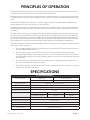
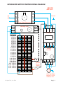
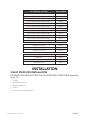
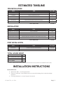
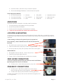
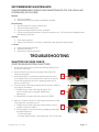
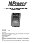
AQUA-LAB EVO™
CHEMICAL DISPENSING SYSTEM
User Manual
REV E
4000003 revE0714
© Hydra-Flex,
Inc. 2014
© Hydra-Flex,
Inc. 2014
© Hydra-Flex, Inc. 2014
TABLE OF CONTENTS
CONTENTS
Principles of Operation1
Specifications 1
AQUA-LAB EVO Components2
Integrated Motor Starter Wiring Diagram
3
Installation4
5 Easy Steps For Installation
4
Estimated Timeline5
Pre-Installation5
Installation5
Post Installation5
Total Hours Spent5
Installation Instructions5
Unpacking6
Location & Mounting6
Feed Water Connection6
Pneumatic Connections6
Startup7
Pump Priming Instructions
7
Optimizing the System7
Injectors vs. Metering tips vs. Nozzles
7
Application Optimization8
Chemical Usage Measuring
8
Recommended Maintenance
9
Troubleshooting9
Injector Vacuum Check (for troubleshooting injectors)
9
Injector Issues
10
Air Operated Valve Replacement
11
Pump Issues
11
Pressure Regulator Issues
12
Flow / Arch Issues
12
Valve Issues
12
Reference13
Chemical Dilution Ratios
13
Chem-Flex Injector Part Numbers
14
Replacement Parts List
15
Warranty16
Appendix A (Pre-Installation Checklist)
17
Appendix B (Optional OEM Instructions)
18-20
© Hydra-Flex, Inc. 2014
PRINCIPLES OF OPERATION
The Aqua-Lab EVO was designed to meet the application requirements of the standard roll-over automatic
car wash with an available pump room to store chemical and equipment.
The system is set-up so that all that is required from the car wash controller is an output signal for each valve.
The EVO electrical control box uses that signal to open both the 3.5 watt air solenoid valves and to start the
pump.
The standard 10 GPM pump produces up to 225 psi of pressure which is regulated down to 200psi by the
bypass regulator. (The pump should never run above 225 psi.)
The 200 psi water flows into the Hydra-Cannon manifold, which is fitted with up to 12 air-actuated valves that
are controlled by air solenoid valves. The water valves control the flow of water to each injector or flow-thru
rinse fitting.
The Chem-Flex injectors are color-coded based on the water flow needed for each individual application, and
combine with color-coded chemical metering tips to proportion the precise chemical mix ratio. As water flows
into the Chem-Flex injector, the velocity increases. As the velocity increases the pressure decreases creating a
vacuum which allows the precise amount of chemical to be pulled into the chamber where it mixes with water.
This precise chemical mixing, along with the proper nozzle, creates an optimal display in the wash bay.
Optional components include an inlet water selection valve, a foaming air wing, a system-protection pressure
switch and a tri-foam manifold.
•
The inlet water selection value is operated using an air solenoid valve. This valve allows the option of
using two different water sources.
•
The foaming air wing can be used for foaming air or as a blow-out frost protection. When the
temperature drops below a certain pre-set point, the car wash controller opens the air valve causing
air to be forced through the lines, clearing them of water or solution that could potentially freeze and
cause damage.
•
The pressure switch is supplied to ensure that if the pump is not getting pressure, a signal will be
sent to the controller to shut the system down.
•
The tri-foam manifold is a three position quick-connect manifold that fits into a single port to support
triple foam or equivalent operations.
SPECIFICATIONS
SYSTEM REQUIREMENTS
Power requirements
10 GPM pump
Air-actuated valves
208-230V/3HP/8A or 460V/3HP/4A
24VDC, 24VDC or 120VAC 3.5 watts per port
Space requirements
38” W x 44” H with pump assembly
Water inlet line
3/4” ID
Pneumatics operating pressure
80 - 100 PSI - Do not operate valves above 100 PSI
Operating ambient temperature
40 - 120° F
Solution outlet
Up to 3.25 GPM
3.25 GPM - 5.5 GPM
5.5 GPM - 8 GPM
3/8” ID (1/2” polyflow)
1/2” ID
5/8” ID
Operating water pressure
200 PSI factory set
Max. water source temperature
140° F (+60° C)
Air inlet line
3/8” OD polyflow
Air outlet line
3/8” OD polyflow per application
Air inlet pressure
20 CFM @ 80 - 100 PSI dry air
© Hydra-Flex, Inc. 2014
Page | 1
AQUA-LAB EVO™ COMPONENTS
Air Pilot Solenoid Valves
1-12 starting at the bottom
right hand side and working
counterclockwise
1
H20 Inlet
Pressure Gauge
Mounting Slots
(2 top, 2 bottom)
12
11
10
9
Integrated
Electrical
Control Box
Air Pilot Solenoid
Valves 9-12
8
7
6
Air Pilot
Solenoid
Valves 5-8
5
Strain Relief
10 GPM Quick
Change Pump
4
3
2
Primary Air
Regulator
1
Inlet Water
Selection Valve
(Optional)
Air Pilot
Solenoid
Valves 1-4
Foaming Air
Solenoid
Valves 13-15
Air Pilot Actuated
Hydra-Cannon
Valve –1-12
starting at the
bottom right
hand side
and working
counterclockwise
Bypass/Pressure
Regulator
Wye Strainer
Multi Conductor
Signal Cable
Three Phase
Power to Pump
Foaming Air or
Frost Protection Air
Valves + Regulators
(Optional)
Three Phase
Power In
Pressure Switch
(optional)
Air Pilot
Solenoid
Valve 16
For Inlet
Water Selector
(optional)
See Appendix B (Optional OEM Instructions) pg.19
© Hydra-Flex, Inc. 2014
Page | 2
INTEGRATED MOTOR STARTER WIRING DIAGRAM
240 OR
480 VAC
Power In
L1
Ground
L2
L3
B1
18
16
A2
Off Delay Timer
A1
15
Three Phase Disconnect
A1
L1
L2
L3
NO
Contacter
Wire / Color
#1
#2
#3
#4
#5
#6
#7
#8
#9
#10
#11
#12
#1 & 2/Black
#3 & 4/Black
#5 & 6/Black
#7 & 8/Black
#9 & 10/Black
#11 & 12/Black
#13 & 14/Black
#15 & 16/Black
#17
#17
#17
#17
#17
#17
#17
#17
#18
#19
#13
#14
#15
#16
Diode Terminal Block
#1/White
#2/White
#3/White
#4/White
#5/White
#6/White
#7/White
#8/White
#9/White
#10/White
#11/White
#12/White
#13/White
#14/White
#15/White
#16/White
A2
T1
T2
T3
NO
Thermal
Overload
24v (-)
95
Remote
Pressure
Switch
24v (+)
96
T1
97
T2
98
T3
Pump
3 HP
Over Load Must
Be Set To 115%
Of Motor FLA
© Hydra-Flex, Inc. 2014
Page | 3
HFI TERMINAL POSITION
WIRE NUMBER
AIR ACTUATED HYDRA-CANNON VALVE-1
WIRE #1
AIR ACTUATED HYDRA-CANNON VALVE-2
WIRE #2
AIR ACTUATED HYDRA-CANNON VALVE-3
WIRE #3
AIR ACTUATED HYDRA-CANNON VALVE-4
WIRE #4
AIR ACTUATED HYDRA-CANNON VALVE-5
WIRE #5
AIR ACTUATED HYDRA-CANNON VALVE-6
WIRE #6
AIR ACTUATED HYDRA-CANNON VALVE-7
WIRE #7
AIR ACTUATED HYDRA-CANNON VALVE-8
WIRE #8
AIR ACTUATED HYDRA-CANNON VALVE-9
WIRE #9
AIR ACTUATED HYDRA-CANNON VALVE-10
WIRE #10
AIR ACTUATED HYDRA-CANNON VALVE-11
WIRE #11
AIR ACTUATED HYDRA-CANNON VALVE-12
WIRE #12
FOAMING AIR VALVE-13
WIRE #13
FOAMING AIR VALVE-14
WIRE #14
FOAMING AIR VALVE-15
WIRE #15
INLET SELECTOR-16
WIRE #16
COMMON-17
WIRE #17
+ CONTROL VOLTAGE-18
WIRE #18
LOW WATER FAULT-19
WIRE #19
INSTALLATION
5 EASY STEPS FOR INSTALLATION
COMPLETE PRE-INSTALLATION CHECKLIST BEFORE THESE STEPS (Appendix
A pg. 17)
1. Unpack
2. Hang the equipment
3. Make connections
4. Start-up
5. Optimizing the system (see p.7 )
© Hydra-Flex, Inc. 2014
Page | 4
ESTIMATED TIMELINE
PRE-INSTALLATION
WHO
TASK
EST. TIME
DISTRIBUTOR & CUSTOMER
DETERMINE LOCATION TO INSTALL EQUIPMENT
1/4 HR
PLUMBER
INSTALL WATER SUPPLY LINE
1 HR
ELECTRICIAN
INSTALL ELECTRICAL SUPPLY LINE
1 HR
TECHNICIAN
LABEL ALL CONTROLLER RELAYS AT CONTROLLER
1/4 HR
TECHNICIAN
RUN SOLUTION AND AIR LINES (IF NECESSARY)
1 HR
TECHNICIAN
INSTALL AIR SUPPLY LINE
1 HR
TOTAL LABOR HOURS
4 1/2 HRS
WHO
TASK
EST. TIME
DISTRIBUTOR / TECHNICIAN
HANG EQUIPMENT
1 HR
TECHNICIAN
CONNECT WATER, AIR AND SOLUTION LINES
1/2 HR
TECHNICIAN
CONNECT CONTROL LEADS TO MAIN CONTROLLER OR JUNCTION BOX
1 HR
DISTRIBUTOR/TECHNICIAN
STARTUP (INJECTOR, METERING TIP AND NOZZLE SELECTION)
1/2 HR
DISTRIBUTOR/TECHNICIAN
DOCUMENT CONFIGURATION
1/2 HR
TOTAL LABOR HOURS
3 1/2 HRS
WHO
TASK
EST. TIME
DISTRIBUTOR
MONITOR & RECORD PERFORMANCE
1 HR / WK
DISTRIBUTOR
MAINTENANCE PER SCHEDULE OR AS NEEDED
INSTALLATION
POST INSTALLATION
TOTAL HOURS SPENT
TOTAL CUSTOMER
1/4 HR
TOTAL DISTRIBUTOR/TECHNICIAN
6 HR
TOTAL ELECTRICIAN
1 HR
TOTAL PLUMBER
1 HR
Installation takes approximately ONE day. An electrician and a plumber are needed for half a day.
INSTALLATION INSTRUCTIONS
General Skill Level
•
Mechanical: Basic - mounting equipment
•
Electrical: Advanced - three phase power and controls knowledge (local codes knowledge
required)
•
Plumbing: Moderate – principal supply line required
© Hydra-Flex, Inc. 2014
Page | 5
•
Pneumatic: Basic- pneumatic utility connection required
•
Chemical Knowledge: Moderate - chemical titrations required
Tools & Equipment Needed
•
Drill with Phillips head
•
Hammer
•
Utility knife
•
Adjustable wrench
•
Concrete drill bit 3/8”
•
Tape measure
•
Wire stripper
•
Screw driver set
•
Concrete drill bit 5/32”
•
Level
•
Socket set
•
Teflon tape
UNPACKING
The AQUA-LAB EVO is shipped in a wooden crate for protection.
1. Cut straps holding crate together, lift off top and sides
2. Un-bolt the pump from the pallet.
3. Lift the pump from the pallet. Use assistance if necessary.
4. ***Be sure not to discard the manuals and accessories box.
LOCATION & MOUNTING
**If location was not identified during the Pre-Installation Process, make sure to consider the proximity
to feed water, power supply, and the control cabinet as well as space near the system to store chemical
containers.
***See drawing in reference for general layout (in appendix A)
Pump Assembly - Need To Be Mounted On Left Side Of Aqua-Lab
Evo Panel
1. Drill 3/8” holes in wall for bottom slots.
2. Insert concrete anchors, set pump on bolts and tighten down.
3. Hold pump stand in place, drill top holes, insert anchors and tighten.
AQUA-LAB EVO
1. Drill (4) 5/32” holes on the wall. 19 1/4” wide, 33” tall.
2. Press EVO board tight against the wall.
3. Screw in 3/16” concrete screws with a washer (not included).
FEED WATER CONNECTION
**Prior To Connection, Ensure That The Feed Lines Are Free Of Debris
By Flushing Out The Lines For 15 Minutes.
•
Connect pre-run main water supply line to pump inlet
PNEUMATIC CONNECTIONS
•
Connect pre-run 3/8” OD poly feed line to push connect
fitting on the side of the primary regulator.
•
Connect 3/8” OD poly lines from EVO to foaming generator.
**If there are unused air ports, back out the individual line regulator until
air no longer flows.
© Hydra-Flex, Inc. 2014
Page | 6
START UP
PUMP PRIMING INSTRUCTIONS
1. Pull the pump outlet line at the manifold quick-connect. Open ball valve and direct toward a drain or
container to remove the majority of the air from the pump until a steady stream of water is flowing
(approx. 1 min).
2. Start the pump using a command from the controller. Ensure
that pump rotation is correct as indicated by the arrow on the
bottom of the pump and that 200 psi can be reached.
•
If pump cannot regulate to 200 psi, remove pump motor
cover and look at shaft to confirm correct rotation.
3. Start the pump and slowly open ball valve until it is wide open.
Allow to run for 60 seconds to flush lines and then close valve.
4. Reconnect the high pressure line to the Hydra-Cannon Manifold
and open valve.
5. Confirm that the pump can obtain 200 psi while firing solenoids
and that the pump housing (stainless steel tube) is cool to the touch after a minute in operation.
•
If housing is hot or noisy, pump did not prime correctly.
6. If pump does not prime, repeat steps 3-5.
7. Verify pump prime 24 hours after operation to ensure prime held. Pay close attention to the
temperature of the pump housing (stainless steel area).If it starts getting hotter than the supply water
or greater than 140°, then it is likely that the pump did not prime correctly which will cause damage
to pumps. The motor housing (painted portion) will be hot during operation.
!WARNING!
PUMP MUST BE PRIMED BEFORE OPERATION.
OPTIMIZING THE SYSTEM
CONSISTENTLY ACHIEVE THE DESIRED CLEANING AND PRESENTATION/
PERFORMANCE USING THE LEAST AMOUNT OF CHEMICAL AND WATER
INJECTORS VS. METERING TIPS VS. NOZZLES
THE KEY TO OPTIMIZING THE SYSTEM IS THROUGH TRIAL AND ERROR. DON’T BE
AFRAID TO TRY THESE STEPS TO ACHIEVE YOUR IDEAL PERFORMANCE.
What do injectors do?
•
Increases or decreases the amount of water
in the solution
What do metering tips do?
•
Increases or decreases the amount of
chemical in the solution
What do nozzles do?
•
Determines the pattern and back pressure
of the solution
© Hydra-Flex, Inc. 2014
Page | 7
APPLICATION OPTIMIZATION
(REPEAT FOR EACH APPLICATION)
•
Application too wet
•
•
•
•
Application too dry
•
•
•
•
Check vacuum of injector (see instructions on page 9)
Check foot valve
Check metering tip
Nozzle fan pattern not filled
•
•
•
Decrease metering tip
Decrease metering tip and injector size (to maintain desired ratio)
No chemical
•
•
•
•
Decrease air
Decrease nozzle(s) and/or size used on arch
Increase injector size (increases water)
Too much chemical used
•
•
•
Decrease air
Increase injector size (increases water)
Decrease metering tip (decreases chemical)
Nozzle sputters
•
•
•
•
Increase air
Reduce injector size (decreases water)
Increase metering tip (increases chemical)
Reduce nozzle size
Increase injector size (increases water)
Water not present at all nozzles on arch
•
•
•
•
•
Verify check valves are functioning
Verify nozzles are not plugged
Reduce number of nozzles
Reduce nozzle size
Increase injector size (increases water)
CHEMICAL USAGE MEASURING
VERIFY TITRATION OF CHEMICALS BEFORE PROCEEDING
1. Set up lab scale with small bucket of chemical to be measured.
2. Put the suction line into the bucket.
3. Run the application being tested to “prime” the line. (All air bubbles must be removed for accuracy.)
4. Record the Initial Weight from the scale. (Tarring the scale with weight on the scale can affect
accuracy.)
5. Run the application for 6 vehicles (or manually for the same it would be on for 6 vehicles).
6. Record the Final Weight from the scale.
7. Subtract the Initial Weight from the Final Weight to determine the weight of used product.
8. Divide this Used Weight by 6 to get a per car weight.
9. Divide the Per Car Weight in grams by the specific gravity of the chemical to determine the milliliters
of chemical used per vehicle.
10. Repeat for each chemical application.
© Hydra-Flex, Inc. 2014
Page | 8
RECOMMENDED MAINTENANCE
THE RECOMMENDED SERVICE AND MAINTENANCE ON THE AQUA-LAB
SYSTEM ARE AS FOLLOWS.
Monthly
•
•
Check air regulator
Check water filter and replace as needed (if installed)
Semi-Annually
•
•
•
•
Check and replace injector metering tips
Check and clean wye strainer
Inspect and replace chemical lines as needed
Ensure lines are tightly secured to injector hose barbs, clip 1” off old hose as needed that was
stretched by hose barb
Annually
•
•
Clean water regulator
Inspect motor starter for corrosion, if identified order replacement/spare parts
1-3 Years
•
•
•
Inspect and replace injectors
Replace water valves
Replace main pressure regulator
TROUBLESHOOTING
INJECTOR VACUUM CHECK
(FOR TROUBLESHOOTING INJECTORS)
1. At the Chem-Flex injector, remove the chemical feed line from
the injector hose barb.
2. Attach the tubing of the vacuum gauge to the Chem-Flex
hose barb (Image A).
3. With the pump(s) on, manually activate the chemical that is
to be tested at the main car wash control cabinet. An injector
that is working properly will have a reading greater than or
equal to (≥) 20 in Hg
4. If vacuum reads <20 in/Hg (image B), remove solution metering
tip (image C) and retest.
a. If retest vacuum reads >20 in/Hg (image D), The
solution metering tip is clogged. Replace the
metering tip.
b. If Retest vacuum reads <20 in/Hg, continue to STEP 5
5. Remove a nozzle on the arch or the chemical feed line from the
foam generator and retest vacuum.
a. If retest vacuum reads >20 in/Hg, back pressure is being
created. Continue to STEP 6.
A
B
C
b. If back pressure is not still not being created try these steps
and retest after each:
1. Clean nozzle tips.
2. Loosely replace media in foam generator. Do no over pack.
© Hydra-Flex, Inc. 2014
Page | 9
3. Decrease air pressure for foaming.
4. Try smaller injector (this will produce less flow and thus less back pressure).
c. If retest vacuum reads <20 in/Hg, replace injector and
retest. If vacuum continues to read <20 in/Hg, call
your service provider.
D
6. Repeat steps 2-5 for each chemical lane that a vacuum reading is needed for.
7. Once testing is complete, turn off the AQUA-LAB pump from the main car wash control cabinet.
There is a variation of performance in the injectors that comes from slight variations in the dimensions of
the parts and in assembly that are unavoidable. It is common to see the resultant vacuum range from 20
in Hg all the way up to 28. There is also variation in the through hole size on the meter tips from Dema
(within their manufacturing tolerances). Using the same tip color from site to site is a good starting
point. However with the potential for variation from part to part it is reasonable to still need to do some
adjustments from there.
INJECTOR ISSUES
PROBLEM
POTENTIAL CAUSES
SOLUTIONS
Injector is not drawing chemical PASSES vacuum pressure check
Clogged chemical feed
Check chemical hose, foot valve, metering tip and hose
barb for debris or clogs
Too much back pressure on injector
Clean or replace downstream check valves, increase
nozzle size or quantity, use larger tubing, or use
smaller flow injectors
Clogged injector check valve
Blow compressed air through the chemical hose barb
on the injector to remove debris
Clogged injector nozzle
Remove injector and blow out any debris with
compressed air
Defective injector
Replace injector
Product specific - Sonny’s Rain Bar
Remove elbow at inlet to foam generator and remove nozzle
Manifold inlet clogged (rare)
Remove end fittings and retention rod. Clean out inlet
holes to allow full flow.
Valve malfunction, valve not opening
Ensure minimum 60 psi on primary air regulator,
ensure valve receiving signal
Clogged injector
Remove injector and blow out debris with
compressed air
No water supply
Check that the system has a supply of water
Strong Acid
Call Hydra-Flex and order composite version of
injectors
Injector is not drawing chemical FAILS vacuum pressure check
No flow from injector
Injector stainless steel
disintegrating
© Hydra-Flex, Inc. 2014
Page | 10
AIR OPERATED VALVE REPLACEMENT
1. Shut off the ball valve to Hydra-Cannon manifold
2. Disconnect air line from front of valve
3. Unscrew quick connect fitting by hand (DON’T LOSE BLACK WASHER)
4. Unscrew valve assembly from the Hydra-Cannon manifold
5. Screw new valve into manifold until hand tight and threaded pilot port is
facing forward
6. Remove the cap from pilot port and thread in quick connect fitting to
front of valve – Hand Tight ONLY
7. Push air line back into fitting
8. Open the ball valve to the Hydra-Cannon manifold
Unscrew from
manifold using this
portion of valve
PUMP ISSUES
PROBLEM
POTENTIAL CAUSES
SOLUTIONS
Pump Operates, But Only
Delivering 100-150 Psi
Incorrect motor rotation
Reverse rotation by interchanging two leads
Pump not priming
See priming instructions
Missing 1 Of 3 phases
Wire according to diagram
Inadequate water supply
Check pressure on inlet side of pump to be sure
positive pressure is maintained
Undersized piping
Replace with larger piping
Leak on the inlet side
Make sure connections are tight
Worn or defective pump parts
Replace worn parts or entire pump, clean parts if
required
Constant hot not connected
Make sure constant control voltage is supplied in car
wash controller.
Blown fuse or circuit breaker
Could be due to blown pump motor. Try to turn breaker
back on or replace fuse. If breaker trips after trying to
fire motor, motor is most likely burned out. Replace
with new motor and pump.
Defective motor starter contactor
Replace motor starter contactor
Thermal overload set too low
Adjust setting on thermal overload to match voltage
Incorrect motor voltage
Voltage must be within 10% of motor rated voltage
Defective motor
Replace motor
E-Stop is depressed
Unlock E-stop
Pump components damaged
Replace worn part or entire pump
Not primed
Re-prime pump
Pump Operates, But Delivers
Little Or No Water
Pump Will Not Start Or Run At
Full Speed
© Hydra-Flex, Inc. 2014
Page | 11
PROBLEM
Excessive Noise From Pump
Pump Leaks
POTENTIAL CAUSES
SOLUTIONS
Pump not secured firmly
Secure properly
Restricted inlet
Clean or correct restriction
Water regulator fluttering /
chattering
Try to adjust regulator down and then back up or
replace regulator
Cavitation (sounds like marbles in
pump)
Increase inlet size
Worn mechanical seal
Replace pump
Loose fittings, and or not enough
thread tape
Tighten fittings, and or take part off and put new
thread tape on
PRESSURE REGULATOR ISSUES
PROBLEM
System Won’t Regulate Up To
200 Psi
POTENTIAL CAUSES
SOLUTIONS
Pump not primed
Follow priming instructions
Debris in regulator
Remove regulator and clean out debris
Motor rotation incorrect
Verify rotation
Opening too many valves at once
System is limited by size of pump and size of injectors,
increase flow by adding secondary pumps or reduce
size / number of injectors open
Defective check valve (if applicable)
Replace check valve
Defective Regulator
Replace regulator
Defective Pump
Replace Pump
FLOW / ARCH ISSUES
PROBLEM
POTENTIAL CAUSES
SOLUTIONS
Incorrect injector flow rate
selection
Replace with larger injector
System pressure too low
Ensure system pressure is set at 200psi
Foam generator plugged
Ensure cleaned and clear
Downstream plumbing restrictive
Increase size of plumbing / tubing, ensure check
valves are cleaned or new, reduce elbows in line or
other turns that would restrict
POTENTIAL CAUSES
SOLUTIONS
Air pressure too low
Ensure primary air regulator reading at least 60 psi, turn
up to 80-90psi if possible and check again
Valve Will Not Open
System pressure too low
Remove valve from manifold, Carefully remove top
of valve (caution – under high spring pressure)
push white piston up with small allen wrench from
opposite end and check o-ring condition. Replace
and lubricate if needed.
Valve Leaks Air Or Water Out
Top
Internal o-ring seal damaged /
worn
Remove valve from manifold, Carefully remove top of
valve (caution – under high spring pressure) push
white piston up with small screwdriver from opposite
end and check o-ring condition. Replace with 018
Viton O-ring and lubricate with Dow 111 valve lube.
Valve Remains Open After Signal
Is Off
Manifold pressure is above 230 psi
Reduce pressure to manifold to 200 psi operating
pressure
Flow At Arch Is Too Low
VALVE ISSUES
PROBLEM
© Hydra-Flex, Inc. 2014
Page | 12
REFERENCE
CHEMICAL DILUTION RATIOS
(Assumes feed pressure of 200 PSI)
Metering Tip
#8-32 METERING TIPS
Flow Rate
(GPM) at 200
PSI
0.25
0.50
0.75
1.00
1.50
2.00
2.25
3.25
5.50
Injector Color
White
Yellow
Tan
Red
Orange
Gray
Blue
Light
Green
Dark
Green
Nozzle
Size
0.029”
(0.7 mm)
0.040”
(1.0 mm)
0.051”
(1.3 mm)
0.057”
(1.4 mm)
0.070”
(1.8 mm)
0.083”
(2.1 mm)
0.086”
(2.2 mm)
0.098”
(2.5 mm)
0.125”
(3.2 mm)
COPPER
1: 57
1: 104
1: 155
1: 146
1: 128
1: 406
1: 468
1: 629
1: 1074
PUMPKIN
1: 43
1: 82
1: 119
1: 126
1: 238
1: 348
1: 398
1: 554
1: 946
BURGUNDY
1: 34
1: 67
1: 97
1: 111
1: 207
1: 304
1: 347
1: 495
1: 845
LIME
1: 28
1: 57
1: 81
1: 100
1: 183
1: 270
1: 307
1: 447
1: 764
TAN
1: 28
1: 57
1: 81
1: 100
1: 183
1: 270
1: 307
1: 447
1: 764
ORANGE
1: 23
1: 44
1: 64
1: 78
1: 137
1: 196
1: 215
1: 314
1: 536
TURQUOISE
1: 17
1: 31
1: 45
1: 55
1: 91
1: 126
1: 134
1: 197
1: 336
PINK
1: 14
1: 24
1: 35
1: 42
1: 68
1: 93
1: 98
1: 143
1: 224
LIGHT BLUE
1: 11
1: 17
1: 24
1: 31
1: 47
1: 64
1: 66
1: 98
1: 166
BROWN
1: 10
1: 15
1: 22
1: 28
1: 43
1: 58
1: 59
1: 88
1: 150
RED
1: 12
1: 17
1: 23
1: 34
1: 45
1: 46
1: 69
1: 116
WHITE
1: 12
1: 16
1: 22
1: 31
1: 42
1: 43
1: 64
1: 108
GREEN
1: 11
1: 14
1: 20
1: 28
1: 37
1: 38
1: 55
1: 94
BLUE
1: 10
1: 12
1: 17
1: 23
1: 30
1: 31
1: 46
1: 77
1: 9
1: 12
1: 16
1: 20
1: 22
1: 31
1: 52
BLACK
1: 10
1: 13
1: 16
1: 17
1: 24
1: 40
PURPLE
1: 6.6
1: 8.3
1: 9
1: 10
1: 13
1: 21
GRAY
1: 5.3
1: 6.7
1: 6.9
1: 7.6
1: 10
1: 16
OPEN
1: 4.9
1: 5.3
1: 5.2
1: 6.0
1: 6.1
1: 10
YELLOW
SPIRAL METERING PLUGS
Spiral Plug Length
Flow Rate
(GPM) at
200 PSI
0.25
0.50
0.75
1.00
1.50
2.00
2.25
3.25
5.50
Injector
Color
White
Yellow
Tan
Red
Orange
Gray
Blue
Light
Green
Dark
Green
Nozzle
Size
0.029”
(0.7 mm)
0.040”
(1.0 mm)
0.051”
(1.3 mm)
0.057”
(1.4 mm)
0.070”
(1.8 mm)
0.083”
(2.1 mm)
0.086”
(2.2 mm)
0.098”
(2.5 mm)
0.125”
(3.2 mm)
3.00”
1: 251
1: 503
1: 754
1: 1006
1: 1509
1: 2012
1: 2263
1: 3269
1: 5532
2.00”
1: 181
1: 363
1: 544
1: 726
1: 1089
1: 1451
1: 1633
1: 2359
1: 3991
1.00“
1: 104
1: 208
1: 311
1: 415
1: 623
1: 831
1: 934
1: 1350
1: 2284
0.75”
1: 82
1: 165
1: 247
1: 329
1: 494
1: 659
1: 741
1: 1071
1: 1812
0.50”
1: 59
1: 119
1: 178
1: 238
1: 357
1: 475
1: 535
1: 772
1: 1307
0.25”
1: 34
1: 68
1: 102
1: 136
1: 204
1: 272
1: 306
1: 442
1: 748
NOTE: Dilution ratios given above are based on drawing water through the metering tips and are
meant as a starting point for system configuration. Results are expected to vary when drawing chemicals
due to differences in viscosity and temperature.
© Hydra-Flex, Inc. 2014
Page | 13
CHEM-FLEX INJECTOR PART NUMBERS
QUICK CONNECT INJECTORS - PC2 X 3/8” NPT CONNECTIONS
(For exclusive use with Aqua-Lab™ Chemical Dispensing Systems)
COLOR
FLOW
ORIFICE
FLOW RATE @
200 PSI
SINGLE BARB
DUAL BARB
TRIPLE BARB
WHITE
0.029
.25 GPM
618029
-
-
YELLOW
0.040
.5 GPM
618040
629040
-
TAN
0.051
.75 GPM
618051
629051
639051
RED
0.057
1 GPM
618057
629057
639057
ORANGE
0.070
1.5 GPM
618070
629070
639070
GRAY
0.083
2.0 GPM
618083
629083
639083
BLUE
0.860
2.25 GPM
618086
629086
639086
LIGHT GREEN
0.098
3.25 GPM
618098
629098
639098
DARK GREEN
0.125
5.5 GPM
618125
629125
639125
Single Hose Barb:
Dual Hose Barb:
Triple Hose Barb:
For diluting one chemical with
water.
For diluting two chemicals with
water. Ideal for adding a color or
scent to your solution.
For diluting three chemicals with
water. Ideal for adding a color
and scent to your solution or for
on-site blending of chemistry.
SPECIFICATIONS:
Pressure Range: up to 1000 PSI Max. (69 Bar) Inlet, 333 PSI (23 Bar) Max. Outlet
Temperature Range: 33°F - 175°F ( .5°C - 79°C)
Maximum Wrench Torque: 30 ft-lbs (41 N-m)
METERING TIPS:
Color-coded tips are used to control the amount of chemical that is mixed with the water and the strength of
the chemical solution.
Threaded In, Standard
Threaded In, Ultra Lean
Spiral Plugs
P/N 1000643
P/N 3000470
P/N 1001290
Pack includes tan, orange,
turquoise, pink, light blue, brown,
red, white, green, blue, yellow,
black, purple, and grey tips.
Pack includes copper, pumpkin,
burgundy, and lime tips.
Meters even greater ratios than ultra
lean tips. Pack includes (10) spiral
plugs, to be inserted into flexible
vinyl chemical tubing, just prior
to the injector. Dilution ratios are
determined by plug length.
© Hydra-Flex, Inc. 2014
Page | 14
REPLACEMENT PARTS LIST - AQUA-LAB EVO™
1
E
T
12
11
10
9
A,B,C,D
F
U
8
7
6
S
5
L
G
Q
4
3
R
2
O
1
K
M
H
P
V
I,J
N
PART NAME
PART NUMBER
A
Contactor
3000864
B
Thermal Overload
3000862
C
Diode Terminal Block
3001200
D
Timer
3000664
E
CPVC Air Valve
3000931
F
24V I Solenoid Cable
3001157
G
10 GPM Pump
3001159
H
Bypass Regulator
3000915
I
Wye Strainer
3000668
J
Wye Strainer Screen
3000517
K
Inlet Ball Valve
3001165
L
Pilot Air Solenoid Valve
3001153
M
Foaming Air Valve
1001429
N
Foaming Air Regulator
3000808
O
Primary Air Regulator
3001160
P
Thermal Relief Valve
3000323
Not Shown
Air Check Valve
3000819
Not Shown
Tan Injector - .75 GPM
618051
Q
Red Injector - 1.0 GPM
618057
Not Shown
Orange Injector - 1.5 GPM
618070
R
Blue Injector - 2.25 GPM
618086
S
Green Injector - 3.25 GPM
618098
T
Flow-Thru Adapter
3000173
Not Shown
Duo-Foam Manifold (Injectors Not Included)
1001232
U
Tri-Foam Manifold (Injectors Not Included)
1001087
Not Shown
O-Ring Replacement Kit
1001155
V
Pressure Switch
3001205
See Appendix B (Optional OEM Instructions) pg.20
© Hydra-Flex, Inc. 2014
Page | 15
AQUA-LAB EVO™ WARRANTY
FACTORY LIMITED
Hydra-Flex, Inc warrants its equipment to be free from defect in material or workmanship under proper
normal use for a period of one (1) year beginning the date of purchase.
Hydra-Flex, Inc’s liability shall be limited to repair or replacement of parts found to be defective within the
warranty period and following Hydra-Flex, Inc’s inspection. Hydra-Flex, Inc shall have the option requiring
the return of defective material to establish the purchaser’s claim. In the event of repair or replacement
this limited warranty is non-cumulative. Neither labor nor transportation charges are included in this
warranty.
This warranty is based upon the proper care and maintenance of the warranted equipment. Warranty
does not apply if the merchandise is altered or modified in any way. Warranty does not apply to any
equipment which has been subject to misuse, inappropriate use of tools, including exposure to harsh
chemicals, neglect, lack of maintenance, freezing, fluid hammer, accident, third party damage, fluid
impurities such as sand or minerals, acts of God or acts of war. Nor does it apply to any equipment which
has been repaired or altered by anyone not so authorized by Hydra-Flex, Inc. All equipment must be
properly installed in accordance with specified plumbing, electrical, and mechanical requirements. The
warranty does not apply to normal wear and tear or routine maintenance components as described in the
equipment manual.
Except as expressly stated herein, Hydra-Flex, Inc shall not be liable for damages of any kind in
connection with the purchase, maintenance, or use of this equipment including loss of profits and all
claims for consequential damages. This limited warranty is in lieu of all other warranties expressed or
implied. Hydra-Flex, Inc neither assumes nor authorizes any person to assume for it any other obligation
or liability in connection herewith. This warranty is neither assignable nor transferable.
Transportation damage claims are to be submitted to the carrier of the damaged material.
680 East Travelers Trail • Burnsville, MN 55337
T: 952-808-3640 • F: 952-808-3650 • www.hydraflexinc.com • [email protected]
© Hydra-Flex, Inc. 2014
4000003 revD0614
Page | 16
APPENDIX A
AQUA-LAB EVO PRE-INSTALLATION CHECKLIST
STEP 1: Determine who will be involved in installation
WHO
NAME
PHONE
Distributor / Technician:
Chem. Supplier:
Car wash Owner:
Site Manager:
Electrician:
Plumber:
Other:
STEP 2: Determine aqua-lab location
• EVO – 38” wide x 44” high
• Pump – 8” wide x 4’ high
STEP 3: Electrician to provide breaker and line run to the location where the motor starter will be
mounted per local code.
• 15 amp Breaker per Operating Pump
STEP 4: Run water supply line to location
• Single Pump – 3/4” Supply Line
STEP 5: Locate main car wash control panel. Identify and label all relays.
STEP 6: Locate main compressed air line and drop a 3/8” feed to the location of the AQUA LAB.
STEP 7: Run new ½” poly lines for solution from the gantry to the location of the AQUA LAB EVO.
• Carefully label each line for the application and chemical.
STEP 8: Run new 3/8” poly lines for air from the gantry to the location of the AQUA LAB EVO.
STEP 9: Confirm delivery of AQUA LAB EVO with HFI
Delivery Date: ________________________
STEP 10: Coordinate Install date with all parties involved
Install Date: ________________________
GENERAL LAYOUT
3612"
2114"
5014"
34"
4518"
1914"
2014"
© Hydra-Flex, Inc. 2014
Page | 17
ISTOBAL SET-UP
HFI TERMINAL WIRE NUMBER
APPENDIX B
DESCRIPTION
RECOMMENDED
INJECTOR
COMMAND POST
TERMINAL
TERM-1
WIRE #1
BRUSH PIPE RINSE
3000173, FLOW THRU
IOAUX3-X5:7
TERM-2
WIRE #2
RINSE PIPES
3000173, FLOW THRU
IOAUX3-X5:8
TERM-3
WIRE #3
WAX
618098, 3.5 GPM - GREEN
TERM-345
TERM-4
WIRE #4
SHAMPOO
618098, 3.5 GPM - GREEN
TERM-346
TERM-5
WIRE #5
TRI-FOAM
(3X) 618057, 1.0 GPM - RED
TERM-349
TERM-6
WIRE #6
S. WAX
618098, 3.25 GPM - GREEN
TERM-348
TERM-7
WIRE #7
PRE-SPRAY
SIDE: 618098, 3.25 GPM - GREEN
TOP: 618086, 2.25 GPM - BLUE
TERM-347
TERM-8
WIRE #8
BASIC FOAM
618098, 3.5 GPM - GREEN
TERM-350
TERM-9
WIRE #9
C.T.A.
618057, 1.0 GPM - RED
IOAUX3-X5:3
TERM-10
WIRE #10
MOSQUITO SPRAY
618051, 0.75 GPM - TAN
IOAUX3-X5:4
TERM-11
WIRE #11
L.P.-U.C.
3000173, FLOW THRU
TERM-327
TERM-12
WIRE #12
SPARE
-
SPARE
TERM-13
WIRE #13
SPARE
-
SPARE
TERM-14
WIRE #14
H.P. BLOWOUT
-
TERM-331
TERM-15
WIRE #15
L.P. BLOWOUT
-
TERM-329
TERM-16
WIRE #16
WATER SELECTION
-
TERM-321
TERM-17
WIRE #17
24 VDC-
-
TERM-112
TERM-18
WIRE #18
24 VDC+
-
TERM-100
TERM-19
WIRE #19
FAULT
-
TERM-356
ISTOBAL M22 / M24 INITIAL SET UP
APPLICATION
INJECTOR
NOZZLE
PRE SPRAY TOP
618086, 2.25 GPM - BLUE
(4X) 11001
PRE SPRAY SIDES
618098, 3.25 GPM - GREEN
(10X) 632.676 (OR 0880 MOSS GREEN)
SHAMPOO
618098, 3.25 GPM - GREEN
(4X) 632.676, (8X) 632.644
SHAMPOO RINSE
FLOW THRU
SEE SHAMPOO
WHITE FOAM
618098 - 3.25 GPM - GREEN
(10X) 632.676 (OR 0680 LIME GREEN)
TRIPLE FOAM
(3X) 618051 - 1.0 GPM EACH - RED
(6X) SHOWER HEAD
WAX / SUPER WAX
618098 - 3.25 GPM - GREEN
SIDE: (2X) 632.676 (OR 0680 LIME GREEN)
HORNS: (2X) 632.886 (OR 0680 LIME GREEN)
HORNS RINSE
FLOW THRU - 3000173
SEE WAX
LOW PRESSURE UNDER SPRAY
FLOW THRU - 3000173
AS SHIPPED
CTA
618051, 0.75 GPM - TAN
(2X) HH-KY-4
BUG SPRAY
618086, 2.25 GPM - BLUE
(4X) 11001
© Hydra-Flex, Inc. 2014
Page | 18
ISTOBAL AQUA-LAB EVO™ COMPONENTS
Air Actuated Hydra-Cannon
Valve –1-12 starting at the
top left hand side and
working clockwise.
1
H20 Inlet
Pressure Gauge
Mounting Slots
(2 top, 2 bottom)
Air Solenoid Valves –
1-16 starting at the top
left hand side and
working clock-wise.
1
2
3
Air Pilot Solenoid
Valves 1-4
4
Integrated
Electrical
Control Box
5
6
7
Air Pilot
Solenoid
Valves 5-8
8
Strain Relief
10 GPM Quick
Change Pump
9
10
Air Pilot
Solenoid
Valves 9-12
11
Primary Air
Regulator
12
Foaming
Air Solenoid
Valves 13-15
Pressure Switch
(optional)
Air Pilot
Solenoid
Valve 16
For Inlet
Water Selector
(optional)
Inlet Water
Selection Valve
(Optional)
Foaming Air or
Frost Protection Air
Valves + Regulators
(Optional)
Three Phase
Power In
Bypass/Pressure
Regulator
Wye Strainer
Multi Conductor
Signal Cable
Three Phase
Power to Pump
For Sales Or Service Contact Istobal USA At:
1-800-336-8795
© Hydra-Flex, Inc. 2014
Page | 19
ISTOBAL REPLACEMENT PARTS LIST - AQUA-LAB EVO™
1
T
1
2
3
E
F
4
A,B,C,D
U
5
6
7
S
8
L
G
Q
9
10
R
11
O
12
M
V
K
H
N
I,J
P
PART NAME
ISTOBAL PART NUMBER
A
Contactor
3000864
B
Thermal Overload
3000862
C
Diode Terminal Block
3001200
D
Timer
3000664
E
CPVC Air Valve
3000931
F
24V I Solenoid Cable
3001157
G
10 GPM Pump
3001159
H
Bypass Regulator
3000915
I
Wye Strainer
3000668
J
Wye Strainer Screen
3000517
K
Inlet Ball Valve
3001165
L
Pilot Air Solenoid Valve
3001153
M
Foaming Air Valve
1001429
N
Foaming Air Regulator
3000808
O
Primary Air Regulator
3001160
P
Thermal Relief Valve
3000323
Not Shown
Air Check Valve
3000819
Not Shown
Tan Injector - .75 GPM
618051
Q
Red Injector - 1.0 GPM
618057
Not Shown
Orange Injector - 1.5 GPM
618070
R
Blue Injector - 2.25 GPM
618086
S
Green Injector - 3.25 GPM
618098
T
Flow-Thru Adapter
3000173
Not Shown
Duo-Foam Manifold (Injectors Not Included)
1001232
U
Tri-Foam Manifold (Injectors Not Included)
1001087
Not Shown
O-Ring Replacement Kit
1001155
V
Pressure Switch
3001205
© Hydra-Flex, Inc. 2014
Page | 20