1
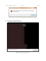
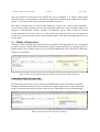
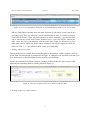
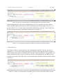
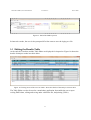
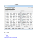
Structure FMEA, User Instruction
Version 1.1
19.11.2010
Tragwerk-FMEA
Computer-based Support for Quality Assurance in Structural Design
User Manual
Tesfaye Regassa, Peter Struss
MQM Group, Technische Universität München
19.11.2010
Version: 1.1
Content
0 Document History ............................................................................................................................ 2
1 Purpose of the Document ................................................................................................................ 2
2 Running the Structure FMEA Demo .................................................................................................. 2
2.1
Starting StructureFMEA ............................................................................................................... 2
2.2
Opening the Structural Concept .................................................................................................. 3
2.3
Selecting Critical Elements........................................................................................................... 4
2.4
Modes of Operation .................................................................................................................... 5
2.5
Editing the Results Table ............................................................................................................. 9
1
Structure FMEA, User Instruction
0
Version 1.1
19.11.2010
Document History
Version
Date
Changes
Author
1.0
18.11.2010
1st draft
Regassa
1.1
19.11.2010
Changed format of document
Regassa
1.2
23.11.2010
Added some new screenshots
Regassa
1
Purpose of the Document
This short manual is intended to give a few instructions on how to start and run the StructureFMEA analysis. It includes instructions only on the User Interfaces incorporated into the
StructureFmea modules and thus does not include instructions on the other libraries incorporated
into the software.
2
Running the Structure FMEA Demo
2.1 Starting StructureFMEA
Starting “StructureFMEA.exe” (double-clicking) will open the main window as shown in Figure
1. Currently the menu point “File” holds the menu items “New” and “Close” only. The menu
point “New” starts a new FMEA session, whereas “Close” exits the application.
Figure 1 Structure FMEA main Window
Choose File/New to open a dialog shown in Figure 2 and enter a project number (input is
required, other wise the button “Start” remains inactive). In addition, one can enter a description
of the project. These inputs will be collected as log data, which can be saved as a text file at the
end of the session.
2
Structure FMEA, User Instruction
Version 1.1
19.11.2010
Figure 2 Clicking File/New opens this new project dialog. Input of Project Number is mandatory
2.2 Opening the Structural Concept
After clicking the button “Start”, the user will be prompted to open a file containing the
Structural Concept. This is presumed to have the extension “.cet”. Otherwise, an error will be
diplayed that the file does not contain a proper Structural Concept. (Figure 4)
Figure 3: An Open File Dialog to open the structural concept (extension “.cet”).
3
Structure FMEA, User Instruction
Version 1.1
19.11.2010
Figure 4: An error report if a file to be opened does not contain a Structural concept
2.3 Selecting Critical Elements
Figure 5: Interaction with the Visualizer
4
Structure FMEA, User Instruction
Version 1.1
19.11.2010
After the Structural concept has been opened, the user is prompted 1st to choose critical fault
elements, and in a second round, to choose the critical effect elements from within the Visualizer
(Figure 5). (The poor contrast gray on black! should be corrected)
The button will show the text “Select Fault Elements”, respectively, “Select Effect Elements”.
To choose the critical elements, the user must click the button once, upon which the button text
changes to “Get Elements”. Before clicking “Get Elements”, the user has to select the desired
critical elements in the Viewer. Here, it is only a mock up selection. In any way, a prepared set
of fault, resp. effect elements will be returned with all their fault and effect definitions as set up
for the demo.
2.4 Modes of Operation
After the critical elements have been retrieved successfully in background, the user is prompted
to choose between a batch mode and interactive mode of operation (Figure 6). In batch mode, the
FMEA analysis runs with the selected sets of Faults/FaultElements and Critical Effect Elements
without user interaction.
Figure 6: The user is prompted to choose a batch or an interactive mode of operation
Interactive Mode of Operation
a. Selecting a Fault Element for Analysis
In an interactive mode, the user can select one FaultElement at a time from the set collected
during the initialization phase (Figure 7) and run the analysis interactively. At the end of both
modes of operation, the analysis results collected in the TableEditor are saved automatically.
Figure 7: Selection of a fault element for analysis
5
Structure FMEA, User Instruction
Version 1.1
19.11.2010
b. Selecting display of results
In an interactive session, the user is prompted if he/she wants to view the intermediate results at
the end of every iteration cycle. For that, the user can choose between the visualizer and the table
editor. The used can inspect the tables viz. the visual display as long as she desires. The selected
form of display remains displayed until the OK button is pressed that then closes the dialog.
Thereafter, the dialog in Figure 8 reappears so that the user can switch to the other form of
display. After enough inspection, the user can press “No Display” to continue with the rest of the
analysis.
Figure 8: Selecting how to display result of an analysis
For this demo, there is no proper display of effects in the visualizer, except entries of resultant
effects in a text box (Figure 9). A data structure exchanged with the Visualizer contains (element
id, reaction type, location, current reaction value, change in %, resulting fault).
Figure 9: A text box showing resulting effects
In the table editor, attributes of the structural element acting as the CriticalFaultElement will be
inserted into the respective columns in Table 1, including: row number, globally unique ID of the
element, its name, function and description, type of fault, its possible cause, its local and system
level effects.
Table 2 is devised as a pivot table upon rows in Table1, and contains results of the computations
of actual member reactions and the associated local effects for all the critical effect elements and
relevant locations in each of them.
6
Structure FMEA, User Instruction
Version 1.1
19.11.2010
Figure 10: View in Table Editor. Each fault of a Structural element produces one row in table1.
NB: the Table Editor currently does not allow insertion of cell values in rows intered in a
preceding cycle. Thus, the whole row can be inserted only at once. It is under revision to
correct this deficiency. Since the final system level effects caused by a given initial fault
can be known only at the end of some iteration cycles, a row can only be entered into
table 1 after the end of all iterations with the fault. Since Table 2 is devised as a pivot
table upon rows in Table1, the detail results of analysis can only be inspected if there are
entries in Table 1; i.e. only when iteration with a given fault ends.
c. Ending analysis of a fault
During an interactive session, the user has the option to prematurely end the iteration cycles of a
given fault, for which he/she is prompted as in Figure 11. Otherwise, the iteration cycle ends if no
new faults occur, or the fault results in some system level instability.
In case the selected fault element contains a number of initial faults, the user can opt to skip
analysing the remaining faults in a dialog shown in Figure 12.
Figure 11: The user can opt to end cycles of iteration with one fault
d. Ending analysis of a fault element
7
Structure FMEA, User Instruction
Version 1.1
19.11.2010
Figure 12: The user can skip analysis of remaining faults of a critical fault element
After finishing analysis of the selected FaultElement, the user is prompted if he/she wants to
analyze another fault element in the set retrieved during the initialization phase (Figure 13). If
the user chooses “Yes”, he/she will be presented the dialog shown in Figure 7 again. Otherwise,
he/she is prompted with the reinitialization dialog shown in Figure 14.
Figure 13: A user prompt (in interactive mode) for selection of next fault element
e. Reinitialization
The dialog in Figure 14, prompts the user for reinitialization if desired. The user can select to
reinitialize (i.e. retrieve anew) either fault elements only (the effect elements will be reused), or
effect elements only (the fault elements will be reused), or retrieve both anew. The procedure can
then be repeated with these new sets. If the user opts for “No Initialization”, the FMEA process
terminates, the results in the table editor saved automatically, and he/she will be shown the dialog
in Figure 15.
Figure 14: A dialog for reinitialization of the FMEA process with new Fault and/or Effect elements
8
Structure FMEA, User Instruction
Version 1.1
19.11.2010
Figure 15: End of the FMEA process
In interactive mode, the user is also prompted if he/she wants to save the loging to a file.
2.5 Editing the Results Table
At the end, the Visualizer and the Table Editor are displayed for inspection. Figure 16 shows the
details of analysis results in a table editor.
Figure 16 Clicking in one of the rows in Table 1 shows the details of the analysis in lower table
The Table Editor can also be used as a stand alone application, that enabls the user to open
exising FMEA data, editing and saving under a different file, and printing (ToDo).
9