1
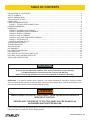
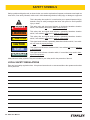
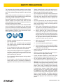
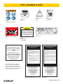
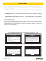
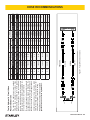
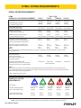
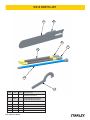
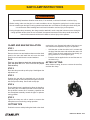
DS12
HYDRAULIC
UTILITY SAW
USER MANUAL
Safety, Operation and Maintenance
© 2012 Stanley Black & Decker, Inc.
New Britain, CT 06053
U.S.A.
71069 2/2015 Ver. 9
DECLARATION OF CONFORMITY
DECLARATION OF CONFORMITY
ÜBEREINSTIMMUNGS-ERKLARUNG
DECLARATION DE CONFORMITE CEE
DECLARACION DE CONFORMIDAD
DICHIARAZIONE DI CONFORMITA
Hydraulic Tools
______________________________________________________________________
I, the undersigned:
Ich, der Unterzeichnende:
Je soussigné:
El abajo firmante:
lo sottoscritto:
Weisbeck, Andy
Surname and First names/Familiennname und Vornamen/Nom et prénom/Nombre y apellido/Cognome e nome
hereby declare that the equipment specified hereunder:
bestätige hiermit, daß erklaren Produkt genannten Werk oder Gerät:
déclare que l’équipement visé ci-dessous:
Por la presente declaro que el equipo se especifica a continuación:
Dichiaro che le apparecchiature specificate di seguito:
Utility Chainsaw, Hydraulic
1.
Category:
Kategorie:
Catégorie:
Categoria:
Categoria:
2.
Make/Marke/Marque/Marca/Marca
3.
Type/Typ/Type/Tipo/Tipo:
4.
Serial number of equipment:
Seriennummer des Geräts:
Numéro de série de l’équipement:
Numero de serie del equipo:
Matricola dell´attrezzatura:
Stanley
DS1231801
All
Has been manufactured in conformity with
Wurde hergestellt in Übereinstimmung mit
Est fabriqué conformément
Ha sido fabricado de acuerdo con
E’ stata costruita in conformitá con
Directive/Standards
Richtlinie/Standards
Directives/Normes
Directriz/Los Normas
Direttiva/Norme
No.
Nr
Numéro
No
n.
Approved body
Prüfung durch
Organisme agréé
Aprobado
Collaudato
EN ISO
12100:2010
Self
EN ISO
ISO
ISO
Machinery Directive
3744:2010
20643:2005
10726:1992
2006/42/EC:2006
Self
Self
Self
Self
5.
Special Provisions:
None
Spezielle Bestimmungen:
Dispositions particulières:
Provisiones especiales:
Disposizioni speciali:
6.
Representative in the Union: Patrick Vervier, Stanley Dubuis 17-19, rue Jules Berthonneau-BP 3406 41034 Blois Cedex, France.
Vertreter in der Union/Représentant dans l’union/Representante en la Union/Rappresentante presso l’Unione
Done at/Ort/Fait à/Dado en/Fatto a Stanley Hydraulic Tools, Milwaukie, Oregon USA
Signature/Unterschrift/Signature/Firma/Firma
Position/Position/Fonction/Cargo/Posizione
2 ► DS12 User Manual
Director of Product Development
Date/Datum/le/Fecha/Data
1-4-11
TABLE OF CONTENTS
DECLARATION OF CONFORMITY...........................................................................................................................2
SAFETY SYMBOLS...................................................................................................................................................4
SAFETY PRECAUTIONS...........................................................................................................................................5
TOOL STICKERS & TAGS.........................................................................................................................................7
HOSE TYPES.............................................................................................................................................................8
HOSE RECOMMENDATIONS...................................................................................................................................9
FIGURE 1. TYPICAL HOSE CONNECTIONS........................................................................................................9
HTMA REQUIREMENTS..........................................................................................................................................10
OPERATION............................................................................................................................................................. 11
FIGURE 2. PROPER CHAIN TENSION............................................................................................................... 11
FIGURE 3. MAXIMUM CHAIN CLEARANCE.......................................................................................................12
FIGURE 4. WHEN TO TENSION..........................................................................................................................12
FIGURE 5. HOW TO TENSION............................................................................................................................12
FIGURE 6. CHECKING FOR PROPER TENSION...............................................................................................12
FIGURE 7. TOP DOWN CUT................................................................................................................................14
FIGURE 8. BOTTOM UP CUT..............................................................................................................................14
SAW BAR MAINTENANCE......................................................................................................................................15
TROUBLESHOOTING.............................................................................................................................................16
SPECIFICATIONS....................................................................................................................................................18
ACCESSORIES.......................................................................................................................................................18
DS12 PARTS ILLUSTRATION.................................................................................................................................19
DS12 PARTS LIST...................................................................................................................................................20
DS12 MOTOR ILLUSTRATION & PARTS LIST.......................................................................................................21
DS12 BAR, CHAIN & HOSES PARTS LIST.............................................................................................................22
SAW CLAMP INSTRUCTIONS................................................................................................................................23
IMPORTANT
To fill out a Product Warranty Validation form, and for information on your warranty,
visit Stanleyhydraulics.com and select the Company tab, Warranty.
(NOTE: The warranty Validation record must be submitted to validate the warranty).
SERVICING: This manual contains safety, operation, and routine maintenance instructions. Stanley Hydraulic
Tools recommends that servicing of hydraulic tools, other than routine maintenance, must be performed by an authorized and certified dealer. Please read the following warning.
WARNING
SERIOUS INJURY OR DEATH COULD RESULT FROM THE IMPROPER REPAIR OR
SERVICE OF THIS TOOL.
REPAIRS AND / OR SERVICE TO THIS TOOL MUST ONLY BE DONE BY AN
AUTHORIZED AND CERTIFIED DEALER.
For the nearest authorized and certified dealer, call Stanley Hydraulic Tools at the number listed on the back of this
manual and ask for a Customer Service Representative.
DS12 User Manual ◄ 3
SAFETY SYMBOLS
Safety symbols and signal words, as shown below, are used to emphasize all operator, maintenance and repair actions which, if not strictly followed, could result in a life-threatening situation, bodily injury or damage to equipment.
This is the safety alert symbol. It is used to alert you to potential personal injury
hazards. Obey all safety messages that follow this symbol to avoid possible
injury or death.
DANGER
This safety alert and signal word indicate an imminently hazardous situation
which, if not avoided, will result in death or serious injury.
WARNING
This safety alert and signal word indicate a potentially hazardous situation
which, if not avoided, could result in death or serious injury.
CAUTION
This safety alert and signal word indicate a potentially hazardous situation
which, if not avoided, could result in death or serious injury.
CAUTION
This signal word indicates a potentially hazardous situation which, if not avoided, may result in property damage.
NOTICE
This signal word indicates a situation which, if not avoided, will result in damage
to the equipment.
IMPORTANT
This signal word indicates a situation which, if not avoided, may result in damage to the equipment.
Always observe safety symbols. They are included for your safety and for the protection of the tool.
LOCAL SAFETY REGULATIONS
Enter any local safety regulations here. Keep these instructions in an area accessible to the operator and maintenance personnel.
4 ► DS12 User Manual
SAFETY PRECAUTIONS
Tool operators and maintenance personnel must always
comply with the safety precautions given in this manual
and on the stickers and tags attached to the tool and
hose.
These safety precautions are given for your safety. Review them carefully before operating the tool and before
performing general maintenance or repairs.
Supervising personnel should develop additional precautions relating to the specific work area and local
safety regulations. If so, place the added precautions in
the space provided in this manual.
•
Always connect hoses to the chain saw hose couplers before energizing the hydraulic power source.
Make sure all hose connections are tight.
•
Do not operate the chain saw at fluid temperatures
above 140 °F/60 °C. Operation at higher temperatures can cause higher than normal temperatures
at the chain saw which can result in operator discomfort.
•
Do not rely exclusively upon the safety devices built
into the chain saw. As a chain saw user, several
steps must be taken to keep your cutting jobs free
from accident or injury:
The DS12 Utility Saw will provide safe and dependable
service if operated in accordance with the instructions
given in this manual. Read and understand this manual
and any stickers and tags attached to the tool and hoses
before operation. Failure to do so could result in personal injury or equipment damage.
a. With a basic understanding of kickbacks, you
can reduce or eliminate the element of surprise.
Sudden surprise contributes to accidents.
b. Keep a good firm grip on the chain saw with
both hands, the right hand on the rear handle
and the left hand on the front handle when operating the chain saw. Use a firm grip with thumbs
and fingers encircling the chain saw handles. A
firm grip helps reduce kickbacks and maintains
control of the chain saw. Do not let go.
•
Establish a training program for all operators to ensure safe operation.
c. Make sure the area in which you are cutting is
free of obstructions.
•
The operator must be familiar with all prohibited
work areas such as excessive slopes and dangerous terrain conditions.
d. Cut at rated operating speeds (gpm).
•
Do not operate the chain saw unless thoroughly
trained or under the supervision of an instructor.
•
Always wear safety equipment such as goggles, ear,
breathing, head protection, leg protection, gloves,
snug fitting clothing and safety shoes at all times
when operating the chain saw.
•
Do not overreach. Maintain proper footing and balance at all times.
•
Do not inspect or clean the chain saw while the hydraulic power source is connected. Accidental engagement of the chain saw can cause serious injury.
e. Do not overreach or cut above shoulder height.
f. Only use replacement bars and chains specified
by Stanley or the equivalent.
•
Make sure the chain guard is in place before operating the chain saw.
•
Remove or control the water slurry to prevent yourself or others from slipping while cutting.
•
Provide adequate ventilation in closed areas when
operating a gas or diesel hydraulic power source.
•
Do not operate a hydraulic power source or a hydraulic diamond saw in an explosive atmosphere.
•
Warning: Use of this tool on certain materials during
demolition could generate dust potentially containing a variety of hazardous substances such as asbestos, silica or lead. Inhalation of dust containing
these or other hazardous substances could result
in serious injury, cancer or death. Protect yourself
and those around you. Research and understand
the materials you are cutting. Follow correct safety
procedures and comply with all applicable national,
state or provisional health and safety regulations
relating to them, including, if appropriate arranging
for the safe disposal of the materials by a qualified
person.
DS12 User Manual ◄ 5
SAFETY PRECAUTIONS
•
Always be well rested and mentally alert before operating the chain saw.
•
Check all chain breaker and rivet spinner components regularly for wear and general condition.
•
Do not allow bystanders near the chain saw when
starting or cutting.
•
Avoid contact with the saw bar rails as they can become very sharp during use.
•
Do not start cutting until you have a clear work area
and secure footing.
•
Provide adequate lighting when operating the saw in
a darkened area or at night.
•
Keep all parts of the body away from the chain saw
during operation, including loose clothing and long
hair.
•
Always keep critical tool markings, such as labels
and warning stickers legible. Always replace stickers and decals that have become worn or damaged.
•
Carry the chain saw with the tool de-energized and
the bar and chain to the rear of your body.
•
•
Do not operate a chain saw that is damaged, improperly adjusted, or not completely and securely
assembled. Make sure the chain stops moving
when the control trigger is released.
Be observant of hydraulic and water hoses that lay
about the work area, especially in trenches where
they can be hidden from view due to liquids that
have accumulated within the space.
•
Keep all parts of the body away from the cleats that
are attached to the saw, as these are sharp and can
be a puncture hazard.
•
Improper handling, use, or maintenance can result
in an oil leak or burst. Do not contact an oil leak as
high pressure oil can cause injection into the body.
•
Never stand in the path of the discharge, as ejection
of material from the work piece can cause personal
injury.
•
Never use the saw in a potentially explosive atmosphere.
•
WARNING: Hydraulic fluid under pressure could
cause skin injection injury. If you are injured by
hydraulic fluid, get medical attention immediately.
•
Keep the handle dry, clean and free of hydraulic
fluid.
•
Do not use the chain saw near energized transmission lines.
•
Turn off the power source or move the hydraulic
control valve to neutral before setting the chain saw
down.
•
Use a guide bar scabbard when transporting the
chain saw.
•
Know the location of buried or covered utilities before starting work.
•
To avoid personal injury or equipment damage, all
chain saw repair, maintenance and service must
only be performed by authorized and properly
trained personnel.
•
Make sure the chain breaker and rivet spinner are
securely mounted on flat, clean work surfaces.
Check the mounting screws/bolts often.
6 ► DS12 User Manual
TOOL STICKERS & TAGS
LWA
28409
Composite Safety Decal
11212
Sound Power
Level Sticker
11207
Type D Circuit
Sticker
71071
Name Tag
DANGER
7-9 GPM / 26-34 LPM
DO NOT EXCEED 2000 PSI / 140 BAR
Failure to use hydraulic hose labeled and certified
as non-conductive when using hydraulic tools on
or near electric lines may result in death or
serious injury.
•DO NOT EXCEED SPECIFIED FLOW OR PRESSURE •USE
CLOSED-CENTER TOOL ON CLOSED-CENTER SYSTEM.
•USE OPEN-CENTER TOOL ON OPEN-CENTER SYSTEM.
•CORRECTLY CONNECT HOSES TO TOOL ‘IN’ AND ‘OUT’
PORTS. •IMPROPER HANDLING, USE OR MAINTENANCE
OF TOOL COULD RESULT IN A LEAK, BURST OR OTHER
TOOL FAILURE. •CONTACT AT A LEAK OR BURST CAN
CAUSE OIL INJECTION INTO THE BODY. •FAILURE TO
OBSERVE THESE PRECAUTIONS CAN RESULT IN SERIOUS
PERSONAL INJURY.
For proper and safe operation read owners manual
and mwke sure that you have been properly
ELECTROCUTION
HAZARD
trained in correct procedures required for work
on or around electric lines.
12412
Electrical Warning Sticker
71073
CE Tool Plate
03786
GPM Sticker
7–9 2000 PSI
NOTE:
THE INFORMATION LISTED
ON THE STICKERS SHOWN,
MUST BE LEGIBLE AT ALL
TIMES.
REPLACE DECALS IF
THEY BECOME WORN OR
DAMAGED. REPLACEMENTS
ARE AVAILABLE FROM
YOUR LOCAL STANLEY
DISTRIBUTOR.
The safety tag (P/N 15875) at right is
attached to the tool when shipped from
the factory. Read and understand the
safety instructions listed on this tag before
removal. We suggest you retain this tag and
attach it to the tool when not in use.
D A N G E R
1.
FAILURE TO USE HYDRAULIC HOSE LABELED AND CERTIFIED AS NON-CONDUCTIVE WHEN USING HYDRAULIC
TOOLS ON OR NEAR ELECTRICAL LINES MAY RESULT IN
DEATH OR SERIOUS INJURY.
BEFORE USING HOSE LABELED AND CERTIFIED AS NONCONDUCTIVE ON OR NEAR ELECTRIC LINES BE SURE THE
HOSE IS MAINTAINED AS NON-CONDUCTIVE. THE HOSE
SHOULD BE REGULARLY TESTED FOR ELECTRIC CURRENT LEAKAGE IN ACCORDANCE WITH YOUR SAFETY
DEPARTMENT INSTRUCTIONS.
2.
A HYDRAULIC LEAK OR BURST MAY CAUSE OIL INJECTION INTO THE BODY OR CAUSE OTHER SEVERE
PERSONAL INJURY.
A.
DO NOT EXCEED SPECIFIED FLOW AND PRESSURE
FOR THIS TOOL. EXCESS FLOW OR PRESSURE MAY
CAUSE A LEAK OR BURST.
B.
DO NOT EXCEED RATED WORKING PRESSURE OF
HYDRAULIC HOSE USED WITH THIS TOOL. EXCESS
PRESSURE MAY CAUSE A LEAK OR BURST.
C. CHECK TOOL HOSE COUPLERS AND CONNECTORS
DAILY FOR LEAKS. DO NOT FEEL FOR LEAKS WITH
YOUR HANDS. CONTACT WITH A LEAK MAY RESULT
IN SEVERE PERSONAL INJURY.
D A N G E R
D. DO NOT LIFT OR CARRY TOOL BY THE HOSES. DO
NOT ABUSE HOSE. DO NOT USE KINKED, TORN OR
DAMAGED HOSE.
3.
MAKE SURE HYDRAULIC HOSES ARE PROPERLY CONNECTED TO THE TOOL BEFORE PRESSURING SYSTEM.
SYSTEM PRESSURE HOSE MUST ALWAYS BE CONNECTED TO TOOL “IN” PORT. SYSTEM RETURN HOSE
MUST ALWAYS BE CONNECTED TO TOOL “OUT” PORT.
REVERSING CONNECTIONS MAY CAUSE REVERSE
TOOL OPERATION WHICH CAN RESULT IN SEVERE
PERSONAL INJURY.
4.
DO NOT CONNECT OPEN-CENTER TOOLS TO CLOSEDCENTER HYDRAULIC SYSTEMS. THIS MAY RESULT IN
LOSS OF OTHER HYDRAULIC FUNCTIONS POWERED BY
THE SAME SYSTEM AND/OR SEVERE PERSONAL INJURY.
5.
BYSTANDERS MAY BE INJURED IN YOUR WORK AREA.
KEEP BYSTANDERS CLEAR OF YOUR WORK AREA.
6.
WEAR HEARING, EYE, FOOT, HAND AND HEAD PROTECTION.
7.
TO AVOID PERSONAL INJURY OR EQUIPMENT DAMAGE,
ALL TOOL REPAIR MAINTENANCE AND SERVICE MUST
ONLY BE PERFORMED BY AUTHORIZED AND PROPERLY
TRAINED PERSONNEL.
I M P O R T A N T
I M P O R T A N T
READ OPERATION MANUAL AND
SAFETY INSTRUCTIONS FOR THIS
TOOL BEFORE USING IT.
READ OPERATION MANUAL AND
SAFETY INSTRUCTIONS FOR THIS
TOOL BEFORE USING IT.
USE ONLY PARTS AND REPAIR
PROCEDURES APPROVED BY
STANLEY AND DESCRIBED IN THE
OPERATION MANUAL.
USE ONLY PARTS AND REPAIR
PROCEDURES APPROVED BY
STANLEY AND DESCRIBED IN THE
OPERATION MANUAL.
TAG TO BE REMOVED ONLY BY
TOOL OPERATOR.
TAG TO BE REMOVED ONLY BY
TOOL OPERATOR.
SEE OTHER SIDE
SEE OTHER SIDE
SAFETY TAG P/N 15875 (Shown smaller then actual size)
DS12 User Manual ◄ 7
HOSE TYPES
The rated working pressure of the hydraulic hose must be equal to or higher than the relief valve setting on the hydraulic system. There are three types of hydraulic hose that meet this requirement and are authorized for use with
Stanley Hydraulic Tools. They are:
Certified non-conductive — constructed of thermoplastic or synthetic rubber inner tube, synthetic fiber braid
reinforcement, and weather resistant thermoplastic or synthetic rubber cover. Hose labeled certified nonconductive is the only hose authorized for use near electrical conductors.
Wire-braided (conductive) — constructed of synthetic rubber inner tube, single or double wire braid reinforcement, and weather resistant synthetic rubber cover. This hose is conductive and must never be used near
electrical conductors.
Fabric-braided (not certified or labeled non-conductive) — constructed of thermoplastic or synthetic rubber inner tube, synthetic fiber braid reinforcement, and weather resistant thermoplastic or synthetic rubber cover. This
hose is not certified non-conductive and must never be used near electrical conductors.
HOSE SAFETY TAGS
To help ensure your safety, the following DANGER tags are attached to all hose purchased from Stanley Hydraulic
Tools. DO NOT REMOVE THESE TAGS.
If the information on a tag is illegible because of wear or damage, replace the tag immediately. A new tag may be
obtained from your Stanley Distributor.
D A N G E R
D A N G E R
1.
FAILURE TO USE HYDRAULIC HOSE LABELED AND CERTIFIED AS NON-CONDUCTIVE
WHEN USING HYDRAULIC TOOLS ON OR NEAR ELECTRIC LINES MAY RESULT IN
DEATH OR SERIOUS INJURY.
FOR PROPER AND SAFE OPERATION MAKE SURE THAT YOU HAVE BEEN PROPERLY TRAINED IN CORRECT PROCEDURES REQUIRED FOR WORK ON OR AROUND
ELECTRIC LINES.
2.
BEFORE USING HYDRAULIC HOSE LABELED AND CERTIFIED AS NON-CONDUCTIVE
ON OR NEAR ELECTRIC LINES. WIPE THE ENTIRE LENGTH OF THE HOSE AND FITTING WITH A CLEAN DRY ABSORBENT CLOTH TO REMOVE DIRT AND MOISTURE AND
TEST HOSE FOR MAXIMUM ALLOWABLE CURRENT LEAKAGE IN ACCORDANCE WITH
SAFETY DEPARTMENT INSTRUCTIONS.
3.
DO NOT EXCEED HOSE WORKING PRESSURE OR ABUSE HOSE. IMPROPER USE
OR HANDLING OF HOSE COULD RESULT IN BURST OR OTHER HOSE FAILURE.
KEEP HOSE AS FAR AWAY AS POSSIBLE FROM BODY AND DO NOT PERMIT DIRECT
CONTACT DURING USE. CONTACT AT THE BURST CAN CAUSE BODILY INJECTION
AND SEVERE PERSONAL INJURY.
4.
HANDLE AND ROUTE HOSE CAREFULLY TO AVOID KINKING, ABRASION, CUTTING, OR
CONTACT WITH HIGH TEMPERATURE SURFACES. DO NOT USE IF KINKED. DO NOT
USE HOSE TO PULL OR LIFT TOOLS, POWER UNITS, ETC.
5.
CHECK ENTIRE HOSE FOR CUTS CRACKS LEAKS ABRASIONS, BULGES, OR DAMAGE TO COUPLINGS IF ANY OF THESE CONDITIONS EXIST, REPLACE THE HOSE
IMMEDIATELY. NEVER USE TAPE OR ANY DEVICE TO ATTEMPT TO MEND THE HOSE.
6.
AFTER EACH USE STORE IN A CLEAN DRY AREA.
SEE OTHER SIDE
SIDE 1
SEE OTHER SIDE
(Shown smaller than actual size)
DO NOT REMOVE THIS TAG
DO NOT REMOVE THIS TAG
THE TAG SHOWN BELOW IS ATTACHED TO “CERTIFIED NON-CONDUCTIVE” HOSE
SIDE 2
D A N G E R
D A N G E R
1.
DO NOT USE THIS HYDRAULIC HOSE ON OR NEAR ELECTRIC LINES. THIS HOSE IS
NOT LABELED OR CERTIFIED AS NON-CONDUCTIVE. USING THIS HOSE ON OR NEAR
ELECTRICAL LINES MAY RESULT IN DEATH OR SERIOUS INJURY.
5.
CHECK ENTIRE HOSE FOR CUTS CRACKS LEAKS ABRASIONS, BULGES, OR DAMAGE TO
COUPLINGS IF ANY OF THESE CONDITIONS EXIST, REPLACE THE HOSE IMMEDIATELY.
NEVER USE TAPE OR ANY DEVICE TO ATTEMPT TO MEND THE HOSE.
2.
FOR PROPER AND SAFE OPERATION MAKE SURE THAT YOU HAVE BEEN PROPERLY
TRAINED IN CORRECT PROCEDURES REQUIRED FOR WORK ON OR AROUND ELECTRIC LINES.
6.
AFTER EACH USE STORE IN A CLEAN DRY AREA.
3.
DO NOT EXCEED HOSE WORKING PRESSURE OR ABUSE HOSE. IMPROPER USE OR
HANDLING OF HOSE COULD RESULT IN BURST OR OTHER HOSE FAILURE. KEEP HOSE
AS FAR AWAY AS POSSIBLE FROM BODY AND DO NOT PERMIT DIRECT CONTACT
DURING USE. CONTACT AT THE BURST CAN CAUSE BODILY INJECTION AND SEVERE
PERSONAL INJURY.
4.
HANDLE AND ROUTE HOSE CAREFULLY TO AVOID KINKING, CUTTING, OR CONTACT
WITH HIGH TEMPERATURE SURFACES. DO NOT USE IF KINKED. DO NOT USE HOSE TO
PULL OR LIFT TOOLS, POWER UNITS, ETC.
SEE OTHER SIDE
SEE OTHER SIDE
SIDE 1
SIDE 2
(Shown smaller than actual size)
8 ► DS12 User Manual
DO NOT REMOVE THIS TAG
DO NOT REMOVE THIS TAG
THE TAG SHOWN BELOW IS ATTACHED TO “CONDUCTIVE” HOSE.
All hydraulic hose must meet or exceed
specifications as set forth by SAE J517.
All hydraulic hose must have at least a rated
minimum working pressure equal to the maximum hydraulic system relief valve setting.
This chart is intended to be used for hydraulic
tool applications only based on Stanley Hydraulic Tools tool operating requirements and
should not be used for any other applications.
The chart to the right shows recommended
minimum hose diameters for various hose
lengths based on gallons per minute (gpm)/
liters per minute (lpm). These recommendations are intended to keep return line pressure
(back pressure) to a minimum acceptable level to ensure maximum tool performance.
Tool to Hydraulic Circuit Hose
Recommendations
15-34
MM
Inside Diameter
INCH
USE
(Press/Return)
PSI
up to 10
up to 3
3/8
10
Both
2250
49-60
13-16
FLOW >>>
RETURN
<<< FLOW
PRESSURE
26-100
up to 25
100-200
51-100
up to 50
100-300
51-100
up to 50
26-100
up to 25
8-30
up to 8
30-60
15-30
up to 15
30-90
15-30
up to 15
7.5-30
up to 7.5
Figure 1. Typical Hose Connections
49-60
38-49
10-13
13-16
19-40
5-10.5
38-49
19-40
5-10.5
10-13
19-40
5-10.5
38-49
15-23
10-13
15-23
4-6
19
25.4
16
19
19
25.4
5/8
3/4
3/4
1
19
3/4
1
16
3/4
16
19
3/4
5/8
16
5/8
5/8
16
13
13
10
5/8
1/2
1/2
3/8
Return
Pressure
Return
Pressure
Return
Pressure
Return
Pressure
Both
Return
Pressure
Both
Both
Both
Both
2500
2500
2500
2500
2500
2500
2500
2500
2500
2500
2500
2500
2500
2500
2500
175
175
175
175
175
175
175
175
175
175
175
175
175
175
175
155
BAR
Min. Working Pressure
Certified Non-Conductive Hose - Fiber Braid - for Utility Bucket Trucks
METERS
Hose Lengths
FEET
Conductive Hose - Wire Braid or Fiber Braid -DO NOT USE NEAR ELECTRICAL CONDUCTORS
4-6
4-9
LPM
Oil Flow
GPM
HOSE RECOMMENDATIONS
DS12 User Manual ◄ 9
HTMA / EHTMA REQUIREMENTS
HTMA / EHTMA REQUIREMENTS
HTMA
HYDRAULIC SYSTEM REQUIREMENTS
TYPE I
Nominal Operating Pressure
(at the power supply outlet)
4-6 gpm
(15-23 lpm)
1500 psi
(103 bar)
TOOL TYPE
TYPE II
TYPE RR
7-9 gpm
(26-34 lpm)
1500 psi
(103 bar)
9-10.5 gpm
(34-40 lpm)
1500 psi
(103 bar)
System relief valve setting
(at the power supply outlet)
2100-2250 psi
(145-155 bar)
2100-2250 psi
(145-155 bar)
2200-2300 psi
(152-159 bar)
2100-2250 psi
(145-155 bar)
Maximum back pressure
(at tool end of the return hose)
250 psi
(17 bar)
250 psi
(17 bar)
250 psi
(17 bar)
250 psi
(17 bar)
Measured at a max. fluid viscosity of:
(at min. operating temperature)
400 ssu*
400 ssu*
400 ssu*
400 ssu*
(82 centistokes) (82 centistokes) (82 centistokes) (82 centistokes)
Temperature: Sufficient heat rejection
capacity to limit max. fluid temperature to:
(at max. expected ambient temperature)
140° F
(60° C)
Flow Range
140° F
(60° C)
140° F
(60° C)
TYPE III
11-13 gpm
(42-49 lpm)
1500 psi
(103 bar)
140° F
(60° C)
3 hp
5 hp
6 hp
7 hp
Min. cooling capacity at a temperature
(2.24 kW)
(3.73 kW)
(5.22 kW)
(4.47 kW)
difference of between ambient and fluid
40° F
40° F
40° F
40° F
temps
(22° C)
(22° C)
(22° C)
(22° C)
NOTE:
Do not operate the tool at oil temperatures above 140° F (60° C). Operation at higher temperatures can cause operator
discomfort at the tool.
Filter
Min. full-flow filtration
Sized for flow of at least:
(For cold temp. startup and max.
dirt-holding capacity)
25 microns
30 gpm
(114 lpm)
Hydraulic fluid Petroleum based
(premium grade, anti-wear, non-conductive)
Viscosity (at min. and max. operating temps)
100-400 ssu*
25 microns
30 gpm
(114 lpm)
25 microns
30 gpm
(114 lpm)
100-400 ssu*
100-400 ssu*
(20-82 centistokes)
25 microns
30 gpm
(114 lpm)
100-400 ssu*
NOTE:
When choosing hydraulic fluid, the expected oil temperature extremes that will be experienced in service determine the
most suitable temperature viscosity characteristics. Hydraulic fluids with a viscosity index over 140 will meet the requirements
over a wide range of operating temperatures.
*SSU = Saybolt Seconds Universal
EHTMA
HYDRAULIC SYSTEM
REQUIREMENTS
CLASSIFICATION
B
C
D
Nominal Operating Pressure
(at the power supply outlet)
3.5-4.3 gpm
(13.5-16.5 lpm)
1870 psi
(129 bar)
4.7-5.8 gpm
(18-22 lpm)
1500 psi
(103 bar)
7.1-8.7 gpm
(27-33 lpm)
1500 psi
(103 bar)
9.5-11.6 gpm
(36-44 lpm)
1500 psi
(103 bar)
11.8-14.5 gpm
(45-55 lpm)
1500 psi
(103 bar)
System relief valve setting
(at the power supply outlet)
2495 psi
(172 bar)
2000 psi
(138 bar)
2000 psi
(138 bar)
2000 psi
(138 bar)
2000 psi
(138 bar)
Flow Range
NOTE: These are general hydraulic system requirements. See tool specification page for tool specific requirements
10 ► DS12 User Manual
OPERATION
PRE-OPERATION PROCEDURES
CHECK THE POWER SOURCE
CHAIN TENSIONING AND BAR
ADJUSTMENT
1. Using a calibrated flow meter and pressure gauge,
make sure the hydraulic power source develops a
flow of 7–9 gpm/26–34 lpm at 2000 psi/140 bar.
2. Make certain that the power source is equipped with
a relief valve set to open at 2100–2250 psi/145–155
bar.
3. Make certain that the power source return pressure
does not exceed 250 psi/17 bar.
CONNECT HYDRAULIC HOSES
1. Wipe all hose couplers with a clean lint-free cloth
before making connections. If necessary, use a
light-weight penetrating oil in a spray can to clean
the hose couplers before each connection.
2. Connect the hoses from the hydraulic power source
to the chain saw fittings or quick disconnects. It is a
good practice to connect return hoes first and disconnect them last to minimize or avoid trapped pressure within the chain saw.
3. Observe the arrow on the couplers to ensure that
the flow is in the proper direction. The female coupler on the chain saw is the inlet (pressure) coupler.
4. Move the hydraulic circuit control valve to the ON
position to operate the chain saw.
NOTE:
If uncoupled hoses are left in the sun, pressure increase inside the hoses might make them difficult to
connect. Whenever possible, connect the free ends
of the hoses together.
IMPORTANT
A properly tensioned chain will optimize cutting
performance. The tensioning rule of thumb for the
utility cutting chain saw is that a properly tensioned
chain must not be bowstring tight and can be pulled
freely around the guide bar by hand easily without
binding. Caution should be used when adjusting
these chains as the bar rail can become very sharp.
Lift the chain away from the bar rail when rotating
and use extreme caution.
NOTE:
The chain on the utility saw is non-directional and
may be installed to travel either direction.
PROPER CHAIN TENSION
Check the chain tension often during operation, especially during the first 1/2 hour when using a new chain.
Adjust the chain accordingly when it becomes loose.
If the chain is too loose, it could come off the bar, or it will
allow the drive sprocket to spin without turning the chain,
which can chew up the chain drive links. If the chain is
too tight, a lot of the saw’s power goes into turning the
chain rather than into the cut. In extreme over-tightened
cases, the saw may not be able to turn the chain at all.
In addition, damage can occur to the bar nose and premature stretch may occur.
CONNECTING TO A WATER SUPPLY
1. Using a standard garden hose, connect the DS12 to
a city or auxiliary water supply.
2. If you plan on operating the chain saw in freezing
weather, make sure you purge all the water from the
system after each use.
Figure 2. Proper Chain Tension
HOW TO CHECK
Before cutting, check for proper tension by pulling the
chain around the bar by hand. If you cannot easily pull
by hand, the chain is too tight and needs to be loosened.
DS12 User Manual ◄ 11
OPERATION
NOTE:
Make sure the bar attaching nuts are fully tightened
and the chain guard is in place.
HOW TO PREVENT CHAIN TENSIONER
BREAKAGE
Figure 3. Maximum Chain Clearance
WHEN TO TENSION
All chains have a tendency to stretch when used. Diamond chains stretch more than wood cutting chains because of the abrasive materials they are cutting. When
a chain stretches to a point where the drive links are
hanging approximately 1/2 in–3/4 in (12–18 mm) below
the bar, it’s time to tension the chain.
Figure 4. When to Tension
HOW TO TENSION
Do not attempt to adjust the tensioner without first loosening the side cover nuts. Do not use the saw without
making sure the side cover nuts are tight. If the side cover nuts are not tight, the bar can slip backwards during
cutting and break the tensioner pin.
ADDITIONAL INFORMATION
Utility chain saws operate with looser chain tension than
wood chain saws. It is common, on the utility chain saw
to have the drive links hang completely out of the bar.
Wood cutting chain saws use oil to lubricate the chain.
The oil makes the chain very slippery and allows the
drive links to fully nest between the teeth of the drive
sprocket. The utility cutting chain saws require water for
cooling and flushing the cut. Water is not as good as oil
as a lubricant. Also, there are cutting particles mixed in
with the water. As a result, sometimes the drive links do
not nest properly on the drive sprocket. When this happens, the chain acts like it got tighter. There seems to
be “tight” spots and “loose” spots as you pull the chain
around the bar. If you tension when the chain is in one
of the loose spots, it will be too tight at some point in it’s
rotation around the bar. Rotating the chain completely
around the bar by hand will let you know you have the
chain properly tensioned.
To tension the chain, first loosen the side cover nuts,
then while holding the nose of the bar up, use a screw
driver to turn the tensioning screw clockwise until the
chain drive links hanging below the bar are just beginning to enter the bar groove. Continue to hold up on the
nose of the bar and firmly tighten the side cover nuts,
(20 ft-lbs, 27 Nm). And remember, it’s the side cover
nuts that hold the bar in position.
Figure 6. Checking for Proper Tension
ADDITIONAL TENSIONING TIPS
1. To reduce chain stretch and tensioning downtime,
use 20 PSI (1.5 bar) or greater water pressure.
2. Oil the chain at the end of the day to prevent rust but
be careful not to over tension in this condition.
Figure 5. How to Tension
12 ► DS12 User Manual
OPERATION
3. When pulling the chain around the bar by hand, be
careful not to touch the bar with thumb or forefinger. The bar rails can be very sharp. Using leather
gloves grab only the diamond segments to pull the
chain.
4. Always turn the hydraulic power source off before
tensioning the chain.
CHECK THE WATER SUPPLY
the intended cut) and then check the chain tension.
4. Adjust accordingly using the procedures contained
in Chain Tensioning and Bar Adjustments section of
this manual.
CUTTING TIPS
If using pipe clamp (Applicable for 4"–12", recommended for 8"–12").
•
Place clamp around top of pipe, hand tighten adjustment nut.
IMPORTANT
•
Chain and bar damage will occur if the chain saw
operates without the proper water supply.
Position saw on pipe for top down or bottom up (recommended) cut and slide saw clamp mount through
receiver hole at top of clamp, secure with snap pin.
•
Slide clamp/saw assembly around pipe to optimum
cutting position and tighten clamp nut with wrench.
•
Ensure saw is positioned to allow handle to pivot
during cut unobstructed, and ensure saw tip doesn’t
contact dirt.
1. Always have water running before starting the chain
saw.
2. Recommended water flow 4 gpm/15 lpm at 50
psi/3.5 bar (2 gpm/7.5 lpm at 20 psi/1.3 bar minimum).
CAUTION
PRE-CUT CHECKLIST
•
If using the clamp make sure it is securely fastened
before attaching the saw, tighten clamp nut with
wrench.
•
Proper Chain tension: Bottom tip of drive link hangs
even with bottom of bar.
•
Ensure proper water flow and hydraulic supply to
power unit.
•
Ensure cut can be made clear of dirt contact.
•
Protective clothing/protection in place.
•
Mark cut on pipe.
•
Block pipe from shifting, support weight of pipe.
WARNING
Before cutting make sure the material being cut is
properly supported from falling or shifting.
When the saw cut is complete be watchful of sharp
edges around the material that has been cut.
CUTTING FREE-HAND OR WITH PIPE
CLAMP
WARNING
When exiting the cut, avoid applying high feed loads
as unexpected movement of the saw may result.
Using both hands, maintain firm control of the tool
throughout the entire cut.
•
Position saw to avoid pinching the bar or chain as
pipe is cut, support pipe from top and side to prevent
cut pipe from injuring operator.
•
Hold saw so chain isn’t in contact with pipe, start
water and activate saw to recommended flow rate,
press chain against pipe slowly, apply pressure to
cut through pipe.
•
Pressure can be applied to cut until saw starts to
lug, if need be back off on the cutting pressure to
maintain a good cutting speed.
•
If cut in a 12" pipe exceeds 5 minutes, cut pulls to
one side, or diamond coating is gone, chain may
need replacement.
OPERATING PROCEDURES
NEW SAW CHAIN BREAK-IN
1. Always make sure the bar and sprocket are in good
condition.
2. Turn on the water supply.
3. Operate the chain saw for two minutes (away from
DS12 User Manual ◄ 13
OPERATION
PLAN THE CUT
1. Plan your cuts to prevent injury to yourself and to
keep from pinching the saw bar and chain as a result of
falling pieces of iron pipe.
2. Outline the material being cut with a permanent marker for a visual guide (especially when cutting free hand).
3. Know what kind of material you are cutting.
TYPES OF CUTS
The DS12 can be operated not only using the pipe clamp
but also make free-hand cuts, any size pipe can be cut
free hand.
UTILITY CHAIN SAW CUTS
• Ductile Iron Pipe
• Roofing Shingles
• Insituform Pipe Lining
• CMU Concrete Block
• PVC Pipe
• Non Reinforced Concrete
• Copper Pipe
• Roofing Tile
Figure 7. Top down Cut
• Steel Roofing Material • Lumber
• HDPE Pipe
• Masonry
1. When using the pipe clamp with a 15-inch bar the
cut capacity is 4" to 10".
2. When using the pipe clamp with a 18-inch bar the
cut capacity is 4" to 12".
3. Do not use a cutting force in excess of 45 lbs/20
kg. Excessive force causes the chain to slow down
or stall and causes premature wear of the saw bar
and chain.
4. Always maintain a high chain speed. High chain
speeds produce the best results.
5. Avoid aggressive/heavy forces. Aggressive force
can causes premature bar and chain wear.
COLD WEATHER OPERATION
If the saw is to be used during cold weather, preheat the
hydraulic fluid at low power source speed. When using
the normally recommended fluids, fluid should be at or
above 50 °F/10 °C (400 ssu/82 centistokes) before use.
Damage to the hydraulic system or chain saw can result
from use with fluid that is too viscous or thick.
14 ► DS12 User Manual
Figure 8. Bottom up Cut
SAW BAR MAINTENANCE
GENERAL MAINTENANCE TIPS
Several simple maintenance tasks which, if performed,
can keep a chain saw operating at a high level
of efficiency. Routine maintenance also keeps
replacement costs down on the parts of the chain saw,
which occasionally wear out.
If any chain saw disassembly is required, refer to the
Service Manual.
SAW BAR RAIL
A quick check can be made to determine if saw bar rail
or chain segment wear exists. Figure 7 shows a worn
saw bar rail.
Figure 7. Rail Wear
If the saw bar rails are worn, use a flat file and dress
each one until it is flat and square with the side of the
saw bar (Figure 7).
Also make sure the saw bar is perfectly straight. If bows
or bends are present in the saw bar, it must be replaced
before dressing any rail.
ROTATING THE SAW BAR
Maximum saw bar life can be achieved by occasionally
turning the bar over so the top and bottom bar surfaces
wear evenly. Refer to the saw bar disassembly procedures in the Service Manual for further details.
DS12 User Manual ◄ 15
TROUBLESHOOTING
Problem
Excessive vibration and cuts rough.
Cause
Solution
Loose chain tension.
Retension the chain.
Excessive feed force.
Reduce feed force.
Chain saw will not cut straight.
Operator feed force not applied
directly over centerline of saw.
Accumulated saw bar wear and
uneven chain segment profile wear.
Move left hand closer to centerline
of saw bar. Turn the saw bar over
and dress rails square. Replace the
saw bar and chain.
Loss of power.
Drive sprocket slipping on
Trantorque® adapter.
Adjust and tighten Trantorque®
adapter, (30 ft. lbs/40.6 Nm).
Chain saw does not run.
Power source not functioning.
Check power source for proper flow
and pressure (7–9 gpm/26–34 lpm
@2000 psi/140 bar).
Coupler or hoses are blocked.
Remove obstruction.
Mechanical failure.
Disassemble the chain saw and
inspect for damage.
Chain saw runs backwards.
Pressure and return hoses
reversed.
Connect for proper flow direction.
Motor shaft must rotate clockwise.
Trigger is hard to press.
Pressure and return hoses
reversed.
Connect to proper flow direction.
Motor shaft must rotate clockwise.
Back pressure too high.
Should not exceed 250 psi/17 bar
@ 9 gpm/34 lpm measured at the
end of the chain saw’s operating
hoses.
Fluid leakage around drive
sprocket.
Motor shaft seal failure.
Replace as required.
Fluid leakage between the rear
gear housing and the chain saw
adaptor.
Motor face seal failure.
Replace as required.
Fluid leakage between the valve
handle and the extension housing.
Oil tube seal failure.
Replace as required.
Fluid leakage between the
extension housing assembly and
the chain saw adaptor.
Oil tube seal failure.
Replace as required.
Chain saw cuts slow.
Insufficient hydraulic fluid flow or
low relief valve setting.
Adjust proper hydraulic fluid flow
to proper gpm. For optimum
performance, adjust relief valve to
2100–2250 psi/145–155 bar.
16 ► DS12 User Manual
TROUBLESHOOTING
Problem
Cause
Chain saw cuts slow.
Excessive vibration and cuts rough.
Solution
Back pressure too high.
Should not exceed 250 psi/17 bar
@ 9 gpm/34 lpm measured at the
end of the chain saw’s operating
hoses.
Loss of diamond segment side
clearance.
Replace the chain.
Hydraulic fluid mixed in water
supply.
Check motor for leaks.
Wrong chain for application.
Scale down to a lower numbered
chain.
Wire edged bar rails.
Dress rails square.
Segment(s) broken or missing from
chain.
Remove and repair broken segment
or replace chain.
NOTICE
In addition to the Safety Precautions found in
this manual, observe the following for equipment
protection and care.
•
Make sure all couplers are wiped clean before connection.
•
The hydraulic circuit control valve must be in the
OFF position when coupling or uncoupling hydraulic tools. Failure to do so may result in damage to
the quick couplers and cause overheating of the hydraulic system.
•
Always store the tool in a clean dry space, safe from
damage or pilferage.
•
Make sure the circuit PRESSURE hose (with male
quick disconnect) is connected to the IN port. The
circuit RETURN hose (with female quick disconnect)
is connected to the opposite port. Do not reverse circuit flow. This can cause damage to internal seals.
•
Always replace hoses, couplings and other parts
with replacement parts recommended by Stanley
Hydraulic Tools. Supply hoses must have a minimum working pressure rating of 2500 psi/172 bar.
•
Do not exceed the rated flow (see Specifications)
page in this manual for correct flow rate and model number. Rapid failure of the internal seals may result.
•
Always keep critical tool markings, such as warning
stickers and tags legible.
•
Tool repair should be performed by experienced personnel only.
•
Make certain that the recommended relief valves are installed in the pressure side of the system.
•
Do not use the tool for applications for which it was not
intended.
•
Oil the chain at the end of the day to prevent rust but be
careful not to over tension in this condition.
DS12 User Manual ◄ 17
SPECIFICATIONS
Input Flow Range......................................................................................................................... 7–9 gpm/26–34 lpm
Input Pressure................................................................................................................................... 2000 psi/140 bar
Chain Type............................................................................................................................Force 4 (.444) inch Pitch
Weight (with bar)....................................................................................................................................26 lbs/11.8 kg
Length............................................................................................................................. 35 or 38 inches/89 or 97 cm
Width....................................................................................................................................................9 inches/23 cm
Lubrication/Cooling........................................................................................................Internal water channels in bar
Porting....................................................................................................................................................-8 SAE O-ring
Connection.........................................................................................3/8 inch Flush-Face Quick Disconnect Coupler
Hose Whips............................................................................................................................................................ Yes
Sound Power Level........................................................................................................................................ 109 dBA
Vibration Level............................................................................................................................Main Handle 4.9 m/s²
Assist Handle 5.2 m/s²
SOUND AND VIBRATION DECLARATION
Test conducted on DS12318, operated at 8 gpm input
Measured A-weighted sound power level, Lwa (ref. 1pW) in decibels
Uncertainty, Kwa, in decibels
Measured A-weighted sound pressure level, Lpa (ref. 20 µPa) at operator’s position, in
decibels
Uncertainty, Kpa, in decibels
109 dBA
3 dBA
101 dBA
3 dBA
Values determined according to noise test code given in ISO 15744, using the basic
standard ISO 3744
NOTE:
The sum of a measured noise emission value and its associated uncertainty represents an upper boundary of the range of values which is likely to occur in measurements.
Declared vibration emission value in accordance with EN 12096
Measured vibration emission value (Main Handle): a
4.9 m/sec²
Uncertainty: K
1.5 m/sec²
Measured vibration emission value (Assist Handle): a
5.2 m/sec²
Uncertainty: K
1.25 m/sec²
Values determined according to ISO 7505, ISO 8662-1, ISO 5349-1,2
ACCESSORIES
Water Pump, 12 VDC, DC Plug, Marine Type............................................................................................ DCP30100
Water Pump, 12 VDC, Battery Clips........................................................................................................... DCP30101
3/8 inch Flush-Face Coupler Set........................................................................................................................03971
25 feet, 1/2 inch Dual Hose with Flush-Face Couplers......................................................................................31972
50 feet, 1/2 inch Dual Hose with Flush-Face Couplers......................................................................................31848
Chain 15-inch ....................................................................................................................................................71050
Bar 15-inch ........................................................................................................................................................71049
Chain 18-inch ....................................................................................................................................................71048
Bar 18-inch ........................................................................................................................................................71047
Pipe Clamp Assembly........................................................................................................................................71055
Drive Sprocket....................................................................................................................................................71046
Water Flow Meter, 0–7 GPM..............................................................................................................................60859
18 ► DS12 User Manual
DS12 PARTS ILLUSTRATION
19
9
20
2
49
59
55
44
42
18
45
4
5
3
11
66
58
33
24
1
16
35
4
57
9
34
67
23
30
17
37
54
32
28
41
12
7
14
Item 39
15
torque to
23-30 ft lbs /
276--360 inch 39
lbs
27
36
13
22
61
48
31
29
64
38
65
52
51
43
50
47
46
10
14
12
13
21
56
DS12 User Manual ◄ 19
DS12 PARTS LIST
ITEM
PART
NO..
QTY
DESCRIPTION
ITEM
PART
NO..
QTY
DESCRIPTION
1
00018
1
O-RING 7/16 X 9/16 X 1/16 -013*
44
22704
1
SAFETY CATCH
2
00112
1
QUAD RING 1/4 X 3/8 X 1/16 -010*
45
22707
1
TRIGGER
3
00174
2
OIL TUBE
46
22713
1
CHAIN SAW ADAPTOR
4
00175
8
O-RING 1/2 X 5/8 X 1/16 -014*
47
22714
1
5/16-18x2.750 FILL. HEAD, SS
5
00787
1
CAPSCREW 1/4-20 X 1-1/4 HSFT SST
48
22715
3
HSBH Capscrew, 5/16-18 x 5/8
7
01211
1
O-RING 5/8 X 3/4 X 1/16 -016*
49
08104
1
PLUG 3/8 SAE
8
01420
1
HELICOIL 5/16-18 UNC X .312 LG.
50
22752
1
NYLOCK NUT 5/16-18UNC
9
01604
2
O-RING .755 X .949 X .097 -910*
51
22945
1
CHAIN COVER
10
01758
4
HSHCS 5/16-18 X 3-1/2
52
23196
2
CAPSCREW 5/16UNCx3/8 HSBH
11
02004
2
#4 X 3/8 DRIVE SCREW
54
25260
1
QUAD RING 3/8 X 1/2 X 1/16 -012*
12
02643
3
WASHER
55
25635
1
FLOW REGLTR.CRTRDG.
13
02649
3
HANDLE BAR RETAINER
56
25688
1
14
02764
3
HSHCS 5/16-18 X 3/4
MOTOR ASSY (SEE PAGE 21 FOR
PARTS)
15
02766
2
WASHER .438" I.D.
57
28409
1
COMPOSITE STICKER
58
28552
1
VALVE HANDLE ASSY (INCLUDES ITEM
49)
59
31804
1
ROLL PIN 1/4 O.D. X 2.000 LG.
61
71046
1
DUCTILE IRON CHAIN SPROCKET
64
71051
1
CHAIN GUARD, DUCTILE IRON
65
71071
1
NAME TAG - DS12
66
71073
1
TOOL PLATE
67
350237
1
HOLLOW HEX PLUG - 8 SAE
16
02912
2
OIL TUBE
17
02916
1
COMPRESSION COIL SPRING
18
02920
1
ON-OFF VALVE SPACER
19
02925
1
VALVE SPOOL
20
02931
1
ON-OFF VALVE CAP
21
02936
1
HANDLE BAR
22
03006
2
CAPSCREW 5/16-18 X 3/4 HSFT
23
03276
2
HEX NUT 3/8-16UNC
24
03278
1
ROLL PIN 3/16 O.D. X 1.375 LG.
27
07473
1
HAND GUARD
28
09437
1
PLUG
29
11207
1
CIRCUIT TYPE "D" STICKER
30
11212
1
SOUND POWER LEVEL STICKER - 109
31
12175
2
WASHER 5/16" I.D.
32
12412
1
DANGER STICKER - ELECTRICAL
33
20453
1
EXTENSION HOUSING
34
20458
1
COMPRESSION COIL SPRING
35
20459
1
HOSE CLIP
36
20461
1
HANDLE STRUT ASSY
37
20463
1
WATER VALVE
38
20465
2
STUD
39
20471
1
TRANTORQUE ADAPTER
41
20721
1
BULK 3/16 CORD STOCK
42
22701
1
TORSION SPRING
43
22702
1
BAR ADJUSTMENT NUT
20 ► DS12 User Manual
* Part of Seal Kit
SEAL KIT P/N 22798
00018
O-RING
1
00112
QUAD RING
1
00173
QUAD RING
1
00175
O-RING
8
00178
O-RING
1
00669
QUAD RING
1
01211
O-RING
2
01604
O-RING
2
01605
O-RING
3
02905
O-RING
1
03110
TEFLON SEAL
1
03847
HOSE WASHER
1
25260
QUAD RING
1
350771
O-RING
1
DS12 MOTOR PARTS LIST
8
1
17
11
2
16
6
23
9
10
5
7
12
18
4
19
15
13
13
3
22
11
14
20
ITEM
PART NO..
QTY
DESCRIPTION
ITEM
PART NO..
QTY
DESCRIPTION
1
00148
1
BEARING
12
03280
1
SPACER, SEAL RACE
2
00170
1
RETAINING RING
13
06316
2
BUSHING, GARLOCK
3
00178
1
O-RING*
14
06838
2
DRIVE GEAR
4
00208
8
HSHCS 1/4-20 X 1-3/4
15
06861
1
5
00633
1
RET RING SPIROLOX INTERNAL
GEAR HOUSING ASSY (INCLUDES
ITEMS 13 & 20)
6
00669
1
QUAD RING*
16
19884
1
SEAL GLAND
7
01211
1
O-RING*
17
20466
1
MOTOR SHAFT
8
02905
1
O-RING*
18
20472
1
RETAINING RING EXTERNAL
9
03104
1
KEEPER-SEAL & BEARING
19
21436
1
10
03110
1
ROTARY SHAFT SEAL *
FRONT BEARING HOUSING ASSY
(INCLUDES ITEM 13)
11
03227
2
DOWEL PIN
20
25444
2
DOWEL PIN 1/4 X 1
22
73308
1
IDLER SHAFT KEYED
23
350771
1
O-RING*
* Part of Seal Kit 22798
DS12 User Manual ◄ 21
DS12 PARTS LIST
62
63
26
25
60
40
53
ITEM
P/N
QTY
DESCRIPTION
25
03972
1
COUPLER 3/8 FEM 3/8 NPT (COUPLER SET P/N-03971)
26
03973
1
COUPLER 3/8 MALE 3/8 NPT
(COUPLER SET P/N-03971)
40
20497
1
WATER HOSE ASSY
53
23517
1
SPROCKET WRENCH
60
56725
1
HOSE ASSY 18 INCH
62
71047
1
DUCTILE IRON CHAIN BAR 18 IN.
63
71048
1
DUCTILE IRON CHAIN 18 IN.
22 ► DS12 User Manual
SAW CLAMP INSTRUCTIONS
WARNING
A potentially hazardous situation exists which, if not avoided, could result in death or serious injury
Before cutting, make sure the pipe is in a safe condition to be cut. Support the work piece in such a way that
the cut remains open during the cutting operation and when the cut is finished. Pinching the chain during the
cut could cause chain breakage and could result in death or serious injury to the operator.
If using the pipe clamp accessory, the clamp must be attached in such a way that it does not move during the
cutting operation and/or when the cut is finished. Unexpected movement of the clamp could cause loss of
control of the saw and could result in death or serious injury to the operator.
CLAMP AND SAW INSTALLATION
STEP 1
Attach the axle to the saw:
Remove the two nuts and washers that secure the chain
guard to the saw and install the axle over the chain
guard, then re-install the two nuts and washers.
NOTE:
This is a good time to check the chain tension on
your saw (see the DS12 Service Manual for proper
chain tension).
STEP 2
as the pipe is cut. Support both ends of the pipe to prevent movement and possible injury to the operator.
•
Hold the saw so that the chain isn’t in contact with
the pipe. Start the water and activate the saw to full
power. Press the chain against the pipe slowly, applying pressure to cut through the pipe.
•
Pressure can be applied to the cut until the saw motor starts to lug.
AFTER CUTTING
When finished cutting, be sure to remove the saw first,
and then the clamp.
Place the clamp around top of the pipe. Hand tighten the
adjustment nut.
STEP 3
Position the saw with the attached axle on the pipe
clamp by sliding the saw clamp axle through the receiver
hole at top of the clamp. Secure with a snap pin.
STEP 4
Ensure that the saw is positioned to allow the handle to
pivot during the cut unobstructed and to ensure that the
saw tip doesn’t contact dirt. If necessary, reposition the
saw clamp/saw assembly around the pipe to optimum
cutting position.
STEP 5
Tighten the clamp nut with a wrench to ensure that
clamp does not move during cutting operation.
CUTTING TIPS
Position the saw to avoid pinching the blade or the chain
DS12 User Manual ◄ 23
Stanley Hydraulic Tools
3810 SE Naef Road
Milwaukie, Oregon 97267-5698 USA
(503) 659-5660 / Fax (503) 652-1780
www.stanleyhydraulics.com