1
PSION
9500 Series
Communications Server Software
User Manual
September 24, 2013
Part No. 8000281.B
ISO 9001 Certified
Quality Management System
© Copyright 2013 by Psion Inc.
2100 Meadowvale Boulevard, Mississauga, Ontario, Canada L5N 7J9
http://www.psion.com
This document and the information it contains is the property of Psion Inc. This document is not to be used,
reproduced or copied, in whole or in part, except for the sole purpose of assisting in proper use of Psion
manufactured goods and services by their rightful owners and users. Any other use of this document is
prohibited.
Disclaimer
Every effort has been made to make this material complete, accurate, and up-to-date. In addition, changes
are periodically incorporated into new editions of the publication.
Psion Inc. reserves the right to make improvements and/or changes in the product(s) and/or the program(s)
described in this document without notice, and shall not be responsible for any damages including, but not
limited to, consequential damages, caused by reliance on the material presented.
Psion, the Psion logo, and the names of other products and services provided by Psion are trademarks of
Psion Inc.
Windows® and the Windows Logo are trademarks or registered trademarks of Microsoft Corporation in the
United States and/or other countries.
The Bluetooth® word mark and logos are owned by Bluetooth SIG, Inc. and any use of such marks by Psion
Inc. is under license.
All trademarks used herein are the property of their respective owners.
Return-To-Factory Warranty
Psion Inc. provides a return to factory warranty on this product for a period of twelve (12) months in accordance with the Statement of Limited Warranty and Limitation of Liability provided at:
http://www.psion.com/us/warranty.htm
The warranty on Psion manufactured equipment does not extend to any product that has been tampered
with, altered, or repaired by any person other than an employee of an authorized Psion service organization. See Psion terms and conditions of sale for full details.
Important:
Psion warranties take effect on the date of shipment.
Service and Information
Psion provides a complete range of product support services and information to its customers worldwide.
Services include technical support and product repairs. To locate your local support services, please go to:
www.psion.com/service-and-support.htm
To access further information on current and discontinued products, please go to our Teknet site and log in
or tap on “Not Registered?”, depending on whether you have previously registered for Teknet:
http://community.psion.com/support
A selection of archived product information is also available online:
http://www.psion.com/products
TABLE OF
CONTENTS
Table of Contents
Chapter 1: Introduction
1.1
1.2
1.3
1.4
1.5
1.6
About this Manual. . . . . . . . . . . . . . . . . . . . . . . . . . . . . . . . . . . . . . . . . . . . . . . . . . . . . . . . . . . . . . . . . . . . . . . . . . . . . . . . . . . . . . . . . . . . . . . . . . . 3
Communications Server Versions . . . . . . . . . . . . . . . . . . . . . . . . . . . . . . . . . . . . . . . . . . . . . . . . . . . . . . . . . . . . . . . . . . . . . . . . . . . . . . . . . 4
Supported Emulations and Protocols . . . . . . . . . . . . . . . . . . . . . . . . . . . . . . . . . . . . . . . . . . . . . . . . . . . . . . . . . . . . . . . . . . . . . . . . . . . . . 4
Text Conventions . . . . . . . . . . . . . . . . . . . . . . . . . . . . . . . . . . . . . . . . . . . . . . . . . . . . . . . . . . . . . . . . . . . . . . . . . . . . . . . . . . . . . . . . . . . . . . . . . . . . 4
Emulations and Datastreams . . . . . . . . . . . . . . . . . . . . . . . . . . . . . . . . . . . . . . . . . . . . . . . . . . . . . . . . . . . . . . . . . . . . . . . . . . . . . . . . . . . . . . 5
Number of Connections . . . . . . . . . . . . . . . . . . . . . . . . . . . . . . . . . . . . . . . . . . . . . . . . . . . . . . . . . . . . . . . . . . . . . . . . . . . . . . . . . . . . . . . . . . . . 6
Chapter 2: Administering The Communications Server
2.1
2.2
2.3
Accessing the Communications Server Browser Interface . . . . . . . . . . . . . . . . . . . . . . . . . . . . . . . . . . . . . . . . . . . . . . . . . . . . . . 9
Accessing Windows Desktop . . . . . . . . . . . . . . . . . . . . . . . . . . . . . . . . . . . . . . . . . . . . . . . . . . . . . . . . . . . . . . . . . . . . . . . . . . . . . . . . . . . . . . . 9
2.2.1
Stopping the Communications Server . . . . . . . . . . . . . . . . . . . . . . . . . . . . . . . . . . . . . . . . . . . . . . . . . . . . . . . . . . . . . . . . . . . 9
2.2.2 Restarting the Communications Server. . . . . . . . . . . . . . . . . . . . . . . . . . . . . . . . . . . . . . . . . . . . . . . . . . . . . . . . . . . . . . . . . 9
2.2.3 Reading Event Log Entries. . . . . . . . . . . . . . . . . . . . . . . . . . . . . . . . . . . . . . . . . . . . . . . . . . . . . . . . . . . . . . . . . . . . . . . . . . . . . . . . 9
Accessing the Debug Console. . . . . . . . . . . . . . . . . . . . . . . . . . . . . . . . . . . . . . . . . . . . . . . . . . . . . . . . . . . . . . . . . . . . . . . . . . . . . . . . . . . . . . 10
Chapter 3: 3274/Telnet Host Configuration
3.1
3.2
3.3
3.4
3.5
3.6
Overview . . . . . . . . . . . . . . . . . . . . . . . . . . . . . . . . . . . . . . . . . . . . . . . . . . . . . . . . . . . . . . . . . . . . . . . . . . . . . . . . . . . . . . . . . . . . . . . . . . . . . . . . . . . . . 13
General Host Options Screen . . . . . . . . . . . . . . . . . . . . . . . . . . . . . . . . . . . . . . . . . . . . . . . . . . . . . . . . . . . . . . . . . . . . . . . . . . . . . . . . . . . . . . 13
3274 Emulation Options Screen . . . . . . . . . . . . . . . . . . . . . . . . . . . . . . . . . . . . . . . . . . . . . . . . . . . . . . . . . . . . . . . . . . . . . . . . . . . . . . . . . . . 14
3.3.1
3274 Options . . . . . . . . . . . . . . . . . . . . . . . . . . . . . . . . . . . . . . . . . . . . . . . . . . . . . . . . . . . . . . . . . . . . . . . . . . . . . . . . . . . . . . . . . . . . . . . 14
3.3.2 TESS Options. . . . . . . . . . . . . . . . . . . . . . . . . . . . . . . . . . . . . . . . . . . . . . . . . . . . . . . . . . . . . . . . . . . . . . . . . . . . . . . . . . . . . . . . . . . . . . . 14
3.3.3 HTML/HTTP Options . . . . . . . . . . . . . . . . . . . . . . . . . . . . . . . . . . . . . . . . . . . . . . . . . . . . . . . . . . . . . . . . . . . . . . . . . . . . . . . . . . . . . . 21
3274 Telnet Protocol Options Screen. . . . . . . . . . . . . . . . . . . . . . . . . . . . . . . . . . . . . . . . . . . . . . . . . . . . . . . . . . . . . . . . . . . . . . . . . . . . . . 21
3.4.1
3274 Telnet Terminal Naming Screen. . . . . . . . . . . . . . . . . . . . . . . . . . . . . . . . . . . . . . . . . . . . . . . . . . . . . . . . . . . . . . . . . . . . 23
3274 Function Key Mappings Screen . . . . . . . . . . . . . . . . . . . . . . . . . . . . . . . . . . . . . . . . . . . . . . . . . . . . . . . . . . . . . . . . . . . . . . . . . . . . . . 23
Typical Host Configuration . . . . . . . . . . . . . . . . . . . . . . . . . . . . . . . . . . . . . . . . . . . . . . . . . . . . . . . . . . . . . . . . . . . . . . . . . . . . . . . . . . . . . . . . . 24
3.6.1
Line Description . . . . . . . . . . . . . . . . . . . . . . . . . . . . . . . . . . . . . . . . . . . . . . . . . . . . . . . . . . . . . . . . . . . . . . . . . . . . . . . . . . . . . . . . . . . 24
3.6.2 Controller Description. . . . . . . . . . . . . . . . . . . . . . . . . . . . . . . . . . . . . . . . . . . . . . . . . . . . . . . . . . . . . . . . . . . . . . . . . . . . . . . . . . . . . 25
3.6.3 TCP/IP Link. . . . . . . . . . . . . . . . . . . . . . . . . . . . . . . . . . . . . . . . . . . . . . . . . . . . . . . . . . . . . . . . . . . . . . . . . . . . . . . . . . . . . . . . . . . . . . . . . 25
Chapter 4: 3274/SNA Host Configuration
4.1
4.2
4.3
4.4
4.5
4.6
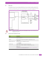
Overview . . . . . . . . . . . . . . . . . . . . . . . . . . . . . . . . . . . . . . . . . . . . . . . . . . . . . . . . . . . . . . . . . . . . . . . . . . . . . . . . . . . . . . . . . . . . . . . . . . . . . . . . . . . . . 29
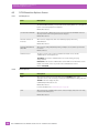
General Host Options Screen . . . . . . . . . . . . . . . . . . . . . . . . . . . . . . . . . . . . . . . . . . . . . . . . . . . . . . . . . . . . . . . . . . . . . . . . . . . . . . . . . . . . . . 29
3274 Emulation Options Screen . . . . . . . . . . . . . . . . . . . . . . . . . . . . . . . . . . . . . . . . . . . . . . . . . . . . . . . . . . . . . . . . . . . . . . . . . . . . . . . . . . . 30
4.3.1
3274 Options . . . . . . . . . . . . . . . . . . . . . . . . . . . . . . . . . . . . . . . . . . . . . . . . . . . . . . . . . . . . . . . . . . . . . . . . . . . . . . . . . . . . . . . . . . . . . . . 30
4.3.2 TESS Options. . . . . . . . . . . . . . . . . . . . . . . . . . . . . . . . . . . . . . . . . . . . . . . . . . . . . . . . . . . . . . . . . . . . . . . . . . . . . . . . . . . . . . . . . . . . . . . 30
4.3.3 HTML/HTTP Options . . . . . . . . . . . . . . . . . . . . . . . . . . . . . . . . . . . . . . . . . . . . . . . . . . . . . . . . . . . . . . . . . . . . . . . . . . . . . . . . . . . . . . 37
3274 SNA Protocol Screen . . . . . . . . . . . . . . . . . . . . . . . . . . . . . . . . . . . . . . . . . . . . . . . . . . . . . . . . . . . . . . . . . . . . . . . . . . . . . . . . . . . . . . . . . 37
3274 Function Key Mappings Screen . . . . . . . . . . . . . . . . . . . . . . . . . . . . . . . . . . . . . . . . . . . . . . . . . . . . . . . . . . . . . . . . . . . . . . . . . . . . . . 38
Typical Host Configuration . . . . . . . . . . . . . . . . . . . . . . . . . . . . . . . . . . . . . . . . . . . . . . . . . . . . . . . . . . . . . . . . . . . . . . . . . . . . . . . . . . . . . . . . . 39
4.6.1
Definition in VTAM. . . . . . . . . . . . . . . . . . . . . . . . . . . . . . . . . . . . . . . . . . . . . . . . . . . . . . . . . . . . . . . . . . . . . . . . . . . . . . . . . . . . . . . . . 39
Chapter 5: 5250/Telnet Host Configuration
5.1
5.2
5.3
Overview . . . . . . . . . . . . . . . . . . . . . . . . . . . . . . . . . . . . . . . . . . . . . . . . . . . . . . . . . . . . . . . . . . . . . . . . . . . . . . . . . . . . . . . . . . . . . . . . . . . . . . . . . . . . . 43
General Host Options Screen . . . . . . . . . . . . . . . . . . . . . . . . . . . . . . . . . . . . . . . . . . . . . . . . . . . . . . . . . . . . . . . . . . . . . . . . . . . . . . . . . . . . . . 43
Emulation Options Screen. . . . . . . . . . . . . . . . . . . . . . . . . . . . . . . . . . . . . . . . . . . . . . . . . . . . . . . . . . . . . . . . . . . . . . . . . . . . . . . . . . . . . . . . . . 44
5.3.1
5250 Options . . . . . . . . . . . . . . . . . . . . . . . . . . . . . . . . . . . . . . . . . . . . . . . . . . . . . . . . . . . . . . . . . . . . . . . . . . . . . . . . . . . . . . . . . . . . . . 44
5.3.2 TESS Options. . . . . . . . . . . . . . . . . . . . . . . . . . . . . . . . . . . . . . . . . . . . . . . . . . . . . . . . . . . . . . . . . . . . . . . . . . . . . . . . . . . . . . . . . . . . . . . 44
5.3.3 HTML/HTTP Options . . . . . . . . . . . . . . . . . . . . . . . . . . . . . . . . . . . . . . . . . . . . . . . . . . . . . . . . . . . . . . . . . . . . . . . . . . . . . . . . . . . . . . 51
Psion 9500 Series Communications Server Software User Manual
i
Table of Contents
5.4
5.5
5.6
5250 Telnet Protocol Options Screen. . . . . . . . . . . . . . . . . . . . . . . . . . . . . . . . . . . . . . . . . . . . . . . . . . . . . . . . . . . . . . . . . . . . . . . . . . . . . 51
5.4.1
5250 Telnet Terminal Naming Screen . . . . . . . . . . . . . . . . . . . . . . . . . . . . . . . . . . . . . . . . . . . . . . . . . . . . . . . . . . . . . . . . . . . 54
Function Key Mappings Options Screen . . . . . . . . . . . . . . . . . . . . . . . . . . . . . . . . . . . . . . . . . . . . . . . . . . . . . . . . . . . . . . . . . . . . . . . . . . 54
Typical Host Configuration . . . . . . . . . . . . . . . . . . . . . . . . . . . . . . . . . . . . . . . . . . . . . . . . . . . . . . . . . . . . . . . . . . . . . . . . . . . . . . . . . . . . . . . . . 55
5.6.1
Line Description . . . . . . . . . . . . . . . . . . . . . . . . . . . . . . . . . . . . . . . . . . . . . . . . . . . . . . . . . . . . . . . . . . . . . . . . . . . . . . . . . . . . . . . . . . . 55
5.6.2 Controller Description . . . . . . . . . . . . . . . . . . . . . . . . . . . . . . . . . . . . . . . . . . . . . . . . . . . . . . . . . . . . . . . . . . . . . . . . . . . . . . . . . . . . 55
5.6.3 TCP/IP Link . . . . . . . . . . . . . . . . . . . . . . . . . . . . . . . . . . . . . . . . . . . . . . . . . . . . . . . . . . . . . . . . . . . . . . . . . . . . . . . . . . . . . . . . . . . . . . . . 56
Chapter 6: 5250/SNA Host Configuration
6.1
6.2
6.3
6.4
6.5
6.6
Overview . . . . . . . . . . . . . . . . . . . . . . . . . . . . . . . . . . . . . . . . . . . . . . . . . . . . . . . . . . . . . . . . . . . . . . . . . . . . . . . . . . . . . . . . . . . . . . . . . . . . . . . . . . . . . 59
General Host Options Screen . . . . . . . . . . . . . . . . . . . . . . . . . . . . . . . . . . . . . . . . . . . . . . . . . . . . . . . . . . . . . . . . . . . . . . . . . . . . . . . . . . . . . . 59
Emulation Options Screen . . . . . . . . . . . . . . . . . . . . . . . . . . . . . . . . . . . . . . . . . . . . . . . . . . . . . . . . . . . . . . . . . . . . . . . . . . . . . . . . . . . . . . . . . 60
6.3.1
5250 Options . . . . . . . . . . . . . . . . . . . . . . . . . . . . . . . . . . . . . . . . . . . . . . . . . . . . . . . . . . . . . . . . . . . . . . . . . . . . . . . . . . . . . . . . . . . . . . 60
6.3.2 TESS Options . . . . . . . . . . . . . . . . . . . . . . . . . . . . . . . . . . . . . . . . . . . . . . . . . . . . . . . . . . . . . . . . . . . . . . . . . . . . . . . . . . . . . . . . . . . . . . 60
6.3.3 HTML/HTTP Options . . . . . . . . . . . . . . . . . . . . . . . . . . . . . . . . . . . . . . . . . . . . . . . . . . . . . . . . . . . . . . . . . . . . . . . . . . . . . . . . . . . . . . 67
Protocol Options Screen . . . . . . . . . . . . . . . . . . . . . . . . . . . . . . . . . . . . . . . . . . . . . . . . . . . . . . . . . . . . . . . . . . . . . . . . . . . . . . . . . . . . . . . . . . . 67
Function Key Mappings Options Screen . . . . . . . . . . . . . . . . . . . . . . . . . . . . . . . . . . . . . . . . . . . . . . . . . . . . . . . . . . . . . . . . . . . . . . . . . . 69
Typical Host Configuration . . . . . . . . . . . . . . . . . . . . . . . . . . . . . . . . . . . . . . . . . . . . . . . . . . . . . . . . . . . . . . . . . . . . . . . . . . . . . . . . . . . . . . . . . 69
6.6.1
The Network Description . . . . . . . . . . . . . . . . . . . . . . . . . . . . . . . . . . . . . . . . . . . . . . . . . . . . . . . . . . . . . . . . . . . . . . . . . . . . . . . . . 69
6.6.2 The Line Description . . . . . . . . . . . . . . . . . . . . . . . . . . . . . . . . . . . . . . . . . . . . . . . . . . . . . . . . . . . . . . . . . . . . . . . . . . . . . . . . . . . . . . 69
6.6.3 Controller Description . . . . . . . . . . . . . . . . . . . . . . . . . . . . . . . . . . . . . . . . . . . . . . . . . . . . . . . . . . . . . . . . . . . . . . . . . . . . . . . . . . . . 71
6.6.4 Device Description . . . . . . . . . . . . . . . . . . . . . . . . . . . . . . . . . . . . . . . . . . . . . . . . . . . . . . . . . . . . . . . . . . . . . . . . . . . . . . . . . . . . . . . . 72
6.6.5 Mode Description. . . . . . . . . . . . . . . . . . . . . . . . . . . . . . . . . . . . . . . . . . . . . . . . . . . . . . . . . . . . . . . . . . . . . . . . . . . . . . . . . . . . . . . . . . 72
Chapter 7: ANSI/Telnet Host Configuration
7.1
7.2
7.3
7.4
7.5
7.6
Overview . . . . . . . . . . . . . . . . . . . . . . . . . . . . . . . . . . . . . . . . . . . . . . . . . . . . . . . . . . . . . . . . . . . . . . . . . . . . . . . . . . . . . . . . . . . . . . . . . . . . . . . . . . . . . 77
General Host Options Screen . . . . . . . . . . . . . . . . . . . . . . . . . . . . . . . . . . . . . . . . . . . . . . . . . . . . . . . . . . . . . . . . . . . . . . . . . . . . . . . . . . . . . . 78
ANSI Emulation Options Screen . . . . . . . . . . . . . . . . . . . . . . . . . . . . . . . . . . . . . . . . . . . . . . . . . . . . . . . . . . . . . . . . . . . . . . . . . . . . . . . . . . . 78
ANSI Telnet Protocol Options Screen . . . . . . . . . . . . . . . . . . . . . . . . . . . . . . . . . . . . . . . . . . . . . . . . . . . . . . . . . . . . . . . . . . . . . . . . . . . . . 80
ANSI Function Key and Arrow Key Mappings Options Screen . . . . . . . . . . . . . . . . . . . . . . . . . . . . . . . . . . . . . . . . . . . . . . . . . . 84
Host Configuration. . . . . . . . . . . . . . . . . . . . . . . . . . . . . . . . . . . . . . . . . . . . . . . . . . . . . . . . . . . . . . . . . . . . . . . . . . . . . . . . . . . . . . . . . . . . . . . . . . 85
Chapter 8: 9010/Telnet Host Configuration
8.1
8.2
8.3
General Host Options . . . . . . . . . . . . . . . . . . . . . . . . . . . . . . . . . . . . . . . . . . . . . . . . . . . . . . . . . . . . . . . . . . . . . . . . . . . . . . . . . . . . . . . . . . . . . . . 89
9010 Emulation Options. . . . . . . . . . . . . . . . . . . . . . . . . . . . . . . . . . . . . . . . . . . . . . . . . . . . . . . . . . . . . . . . . . . . . . . . . . . . . . . . . . . . . . . . . . . . 89
9010 Protocol Options Screen . . . . . . . . . . . . . . . . . . . . . . . . . . . . . . . . . . . . . . . . . . . . . . . . . . . . . . . . . . . . . . . . . . . . . . . . . . . . . . . . . . . . . 89
Chapter 9: 2392/Telnet Host Configuration
9.1
9.2
9.3
9.4
Overview . . . . . . . . . . . . . . . . . . . . . . . . . . . . . . . . . . . . . . . . . . . . . . . . . . . . . . . . . . . . . . . . . . . . . . . . . . . . . . . . . . . . . . . . . . . . . . . . . . . . . . . . . . . . . 93
General Host Options . . . . . . . . . . . . . . . . . . . . . . . . . . . . . . . . . . . . . . . . . . . . . . . . . . . . . . . . . . . . . . . . . . . . . . . . . . . . . . . . . . . . . . . . . . . . . . . 93
2392 Emulation Options Screen . . . . . . . . . . . . . . . . . . . . . . . . . . . . . . . . . . . . . . . . . . . . . . . . . . . . . . . . . . . . . . . . . . . . . . . . . . . . . . . . . . . 94
9.3.1
2392 Options. . . . . . . . . . . . . . . . . . . . . . . . . . . . . . . . . . . . . . . . . . . . . . . . . . . . . . . . . . . . . . . . . . . . . . . . . . . . . . . . . . . . . . . . . . . . . . . 94
9.3.2 TESS Options . . . . . . . . . . . . . . . . . . . . . . . . . . . . . . . . . . . . . . . . . . . . . . . . . . . . . . . . . . . . . . . . . . . . . . . . . . . . . . . . . . . . . . . . . . . . . . 94
2392 Telnet Protocol Options Screen . . . . . . . . . . . . . . . . . . . . . . . . . . . . . . . . . . . . . . . . . . . . . . . . . . . . . . . . . . . . . . . . . . . . . . . . . . . . . 101
Chapter 10: RF Modem/Telnet Host Configuration
10.1
10.2
General Host Options Screen . . . . . . . . . . . . . . . . . . . . . . . . . . . . . . . . . . . . . . . . . . . . . . . . . . . . . . . . . . . . . . . . . . . . . . . . . . . . . . . . . . . . . . 105
Telnet Protocol Options Screen. . . . . . . . . . . . . . . . . . . . . . . . . . . . . . . . . . . . . . . . . . . . . . . . . . . . . . . . . . . . . . . . . . . . . . . . . . . . . . . . . . . . 105
Chapter 11: HTML Host Configuration
11.1
11.2
ii
Overview . . . . . . . . . . . . . . . . . . . . . . . . . . . . . . . . . . . . . . . . . . . . . . . . . . . . . . . . . . . . . . . . . . . . . . . . . . . . . . . . . . . . . . . . . . . . . . . . . . . . . . . . . . . . . 109
General Host Options Screen . . . . . . . . . . . . . . . . . . . . . . . . . . . . . . . . . . . . . . . . . . . . . . . . . . . . . . . . . . . . . . . . . . . . . . . . . . . . . . . . . . . . . . 109
Psion 9500 Series Communications Server Software User Manual
Table of Contents
11.3
11.4
HTML Emulation Options Screen . . . . . . . . . . . . . . . . . . . . . . . . . . . . . . . . . . . . . . . . . . . . . . . . . . . . . . . . . . . . . . . . . . . . . . . . . . . . . . . . . . 110
11.3.1
HTML Options. . . . . . . . . . . . . . . . . . . . . . . . . . . . . . . . . . . . . . . . . . . . . . . . . . . . . . . . . . . . . . . . . . . . . . . . . . . . . . . . . . . . . . . . . . . . . . 110
11.3.2 TESS Options . . . . . . . . . . . . . . . . . . . . . . . . . . . . . . . . . . . . . . . . . . . . . . . . . . . . . . . . . . . . . . . . . . . . . . . . . . . . . . . . . . . . . . . . . . . . . . 110
HTML Function Key Mappings Screen. . . . . . . . . . . . . . . . . . . . . . . . . . . . . . . . . . . . . . . . . . . . . . . . . . . . . . . . . . . . . . . . . . . . . . . . . . . . . 111
Chapter 12: Remote Socket Emulation Host Configuration
12.1
12.2
12.3
12.4
12.5
Overview . . . . . . . . . . . . . . . . . . . . . . . . . . . . . . . . . . . . . . . . . . . . . . . . . . . . . . . . . . . . . . . . . . . . . . . . . . . . . . . . . . . . . . . . . . . . . . . . . . . . . . . . . . . . . 115
General Host Options Screen . . . . . . . . . . . . . . . . . . . . . . . . . . . . . . . . . . . . . . . . . . . . . . . . . . . . . . . . . . . . . . . . . . . . . . . . . . . . . . . . . . . . . . 115
Other Communications Server Settings Associated with Remote Sockets. . . . . . . . . . . . . . . . . . . . . . . . . . . . . . . . . . . . 116
Mobile Device Narrow Band Configuration for Remote Sockets. . . . . . . . . . . . . . . . . . . . . . . . . . . . . . . . . . . . . . . . . . . . . . . . 116
Base Station Narrow Band Configuration for Remote Sockets . . . . . . . . . . . . . . . . . . . . . . . . . . . . . . . . . . . . . . . . . . . . . . . . . 116
Chapter 13: Base Station Configuration
13.1
Overview . . . . . . . . . . . . . . . . . . . . . . . . . . . . . . . . . . . . . . . . . . . . . . . . . . . . . . . . . . . . . . . . . . . . . . . . . . . . . . . . . . . . . . . . . . . . . . . . . . . . . . . . . . . . . 119
13.2
13.3
General Options Screen . . . . . . . . . . . . . . . . . . . . . . . . . . . . . . . . . . . . . . . . . . . . . . . . . . . . . . . . . . . . . . . . . . . . . . . . . . . . . . . . . . . . . . . . . . . . 119
Connectivity Options: TCP/IP Options for Base Station Screen . . . . . . . . . . . . . . . . . . . . . . . . . . . . . . . . . . . . . . . . . . . . . . . . 119
Chapter 14: RRM Groups Configuration
14.1
14.2
14.3
14.4
Overview . . . . . . . . . . . . . . . . . . . . . . . . . . . . . . . . . . . . . . . . . . . . . . . . . . . . . . . . . . . . . . . . . . . . . . . . . . . . . . . . . . . . . . . . . . . . . . . . . . . . . . . . . . . . . 123
General Options Screen: Configure RRM Group Screen . . . . . . . . . . . . . . . . . . . . . . . . . . . . . . . . . . . . . . . . . . . . . . . . . . . . . . . . . 123
14.2.1 General Options Parameters . . . . . . . . . . . . . . . . . . . . . . . . . . . . . . . . . . . . . . . . . . . . . . . . . . . . . . . . . . . . . . . . . . . . . . . . . . . . . 123
14.2.2 Polling Protocol Parameters. . . . . . . . . . . . . . . . . . . . . . . . . . . . . . . . . . . . . . . . . . . . . . . . . . . . . . . . . . . . . . . . . . . . . . . . . . . . . . 123
14.2.3 Radio Parameters . . . . . . . . . . . . . . . . . . . . . . . . . . . . . . . . . . . . . . . . . . . . . . . . . . . . . . . . . . . . . . . . . . . . . . . . . . . . . . . . . . . . . . . . . 124
14.2.4 Group Parameters . . . . . . . . . . . . . . . . . . . . . . . . . . . . . . . . . . . . . . . . . . . . . . . . . . . . . . . . . . . . . . . . . . . . . . . . . . . . . . . . . . . . . . . . . 125
RRMs Screen: Configure RRM Screen. . . . . . . . . . . . . . . . . . . . . . . . . . . . . . . . . . . . . . . . . . . . . . . . . . . . . . . . . . . . . . . . . . . . . . . . . . . . . 125
Analyze Screen: Analyze RRM Group Screen . . . . . . . . . . . . . . . . . . . . . . . . . . . . . . . . . . . . . . . . . . . . . . . . . . . . . . . . . . . . . . . . . . . . 125
14.4.1 General Parameters. . . . . . . . . . . . . . . . . . . . . . . . . . . . . . . . . . . . . . . . . . . . . . . . . . . . . . . . . . . . . . . . . . . . . . . . . . . . . . . . . . . . . . . 126
14.4.2 Polling Protocol Parameters . . . . . . . . . . . . . . . . . . . . . . . . . . . . . . . . . . . . . . . . . . . . . . . . . . . . . . . . . . . . . . . . . . . . . . . . . . . . . 126
14.4.3 Radio Parameters . . . . . . . . . . . . . . . . . . . . . . . . . . . . . . . . . . . . . . . . . . . . . . . . . . . . . . . . . . . . . . . . . . . . . . . . . . . . . . . . . . . . . . . . . 126
14.4.4 Group Parameters. . . . . . . . . . . . . . . . . . . . . . . . . . . . . . . . . . . . . . . . . . . . . . . . . . . . . . . . . . . . . . . . . . . . . . . . . . . . . . . . . . . . . . . . . 127
14.4.5 Results. . . . . . . . . . . . . . . . . . . . . . . . . . . . . . . . . . . . . . . . . . . . . . . . . . . . . . . . . . . . . . . . . . . . . . . . . . . . . . . . . . . . . . . . . . . . . . . . . . . . . . 127
Chapter 15: Radio Link Features Configuration
15.1
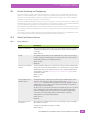
15.2
Cellular Switching and Timeplexing . . . . . . . . . . . . . . . . . . . . . . . . . . . . . . . . . . . . . . . . . . . . . . . . . . . . . . . . . . . . . . . . . . . . . . . . . . . . . . . 131
Radio Link Features Screen . . . . . . . . . . . . . . . . . . . . . . . . . . . . . . . . . . . . . . . . . . . . . . . . . . . . . . . . . . . . . . . . . . . . . . . . . . . . . . . . . . . . . . . . 131
15.2.1 General Options . . . . . . . . . . . . . . . . . . . . . . . . . . . . . . . . . . . . . . . . . . . . . . . . . . . . . . . . . . . . . . . . . . . . . . . . . . . . . . . . . . . . . . . . . . . 131
15.2.2 Automatic Terminal Number Assignment. . . . . . . . . . . . . . . . . . . . . . . . . . . . . . . . . . . . . . . . . . . . . . . . . . . . . . . . . . . . . . . 132
Chapter 16: 802.IQ v1 and v2 Features Configuration
16.1
16.2
802.IQ Protocol . . . . . . . . . . . . . . . . . . . . . . . . . . . . . . . . . . . . . . . . . . . . . . . . . . . . . . . . . . . . . . . . . . . . . . . . . . . . . . . . . . . . . . . . . . . . . . . . . . . . . 135
802.IQ version 1 and version 2 Configuration Screen . . . . . . . . . . . . . . . . . . . . . . . . . . . . . . . . . . . . . . . . . . . . . . . . . . . . . . . . . . . 135
16.2.1 802.IQ v1/v2 Common Features. . . . . . . . . . . . . . . . . . . . . . . . . . . . . . . . . . . . . . . . . . . . . . . . . . . . . . . . . . . . . . . . . . . . . . . . . . 135
16.2.2 Available Interfaces . . . . . . . . . . . . . . . . . . . . . . . . . . . . . . . . . . . . . . . . . . . . . . . . . . . . . . . . . . . . . . . . . . . . . . . . . . . . . . . . . . . . . . . 135
16.2.3 802.IQ v1 Features. . . . . . . . . . . . . . . . . . . . . . . . . . . . . . . . . . . . . . . . . . . . . . . . . . . . . . . . . . . . . . . . . . . . . . . . . . . . . . . . . . . . . . . . . 135
16.2.4 802.IQ v2 Features . . . . . . . . . . . . . . . . . . . . . . . . . . . . . . . . . . . . . . . . . . . . . . . . . . . . . . . . . . . . . . . . . . . . . . . . . . . . . . . . . . . . . . . . 136
Chapter 17: Redundancy Configuration
17.1
17.2
Overview . . . . . . . . . . . . . . . . . . . . . . . . . . . . . . . . . . . . . . . . . . . . . . . . . . . . . . . . . . . . . . . . . . . . . . . . . . . . . . . . . . . . . . . . . . . . . . . . . . . . . . . . . . . . . 139
Redundancy Parameters Screen . . . . . . . . . . . . . . . . . . . . . . . . . . . . . . . . . . . . . . . . . . . . . . . . . . . . . . . . . . . . . . . . . . . . . . . . . . . . . . . . . . 140
17.2.1
General Redundancy Options . . . . . . . . . . . . . . . . . . . . . . . . . . . . . . . . . . . . . . . . . . . . . . . . . . . . . . . . . . . . . . . . . . . . . . . . . . . . 140
17.2.2 Available interfaces. . . . . . . . . . . . . . . . . . . . . . . . . . . . . . . . . . . . . . . . . . . . . . . . . . . . . . . . . . . . . . . . . . . . . . . . . . . . . . . . . . . . . . . . 140
Chapter 18: SNA Protocol Configuration
18.1
SNA Protocol Configuration: SNA Parameters Screen. . . . . . . . . . . . . . . . . . . . . . . . . . . . . . . . . . . . . . . . . . . . . . . . . . . . . . . . . . 145
Psion 9500 Series Communications Server Software User Manual
iii
Table of Contents
Chapter 19: System Configuration
19.1
19.2
19.3
User Screen. . . . . . . . . . . . . . . . . . . . . . . . . . . . . . . . . . . . . . . . . . . . . . . . . . . . . . . . . . . . . . . . . . . . . . . . . . . . . . . . . . . . . . . . . . . . . . . . . . . . . . . . . . 149
SNMP Parameters Screen . . . . . . . . . . . . . . . . . . . . . . . . . . . . . . . . . . . . . . . . . . . . . . . . . . . . . . . . . . . . . . . . . . . . . . . . . . . . . . . . . . . . . . . . . . 149
Miscellaneous Options Screen . . . . . . . . . . . . . . . . . . . . . . . . . . . . . . . . . . . . . . . . . . . . . . . . . . . . . . . . . . . . . . . . . . . . . . . . . . . . . . . . . . . . . 149
Chapter 20: Miscellaneous Commands Configuration
20.1
20.2
20.3
20.4
Display Entire Database Contents: Database Validation Results Screen. . . . . . . . . . . . . . . . . . . . . . . . . . . . . . . . . . . . . . . 153
Export/Import Configuration: Configuration Database Import/Export Menu . . . . . . . . . . . . . . . . . . . . . . . . . . . . . . . . . 153
Restart Communications Server Software . . . . . . . . . . . . . . . . . . . . . . . . . . . . . . . . . . . . . . . . . . . . . . . . . . . . . . . . . . . . . . . . . . . . . . . 153
Validate and Save Current Configuration . . . . . . . . . . . . . . . . . . . . . . . . . . . . . . . . . . . . . . . . . . . . . . . . . . . . . . . . . . . . . . . . . . . . . . . . . 153
Chapter 21: Setting Terminal Numbers on the General Host Options Screen
21.1
Introduction . . . . . . . . . . . . . . . . . . . . . . . . . . . . . . . . . . . . . . . . . . . . . . . . . . . . . . . . . . . . . . . . . . . . . . . . . . . . . . . . . . . . . . . . . . . . . . . . . . . . . . . . . 157
21.2
21.3
Systems with One Host. . . . . . . . . . . . . . . . . . . . . . . . . . . . . . . . . . . . . . . . . . . . . . . . . . . . . . . . . . . . . . . . . . . . . . . . . . . . . . . . . . . . . . . . . . . . . 157
Systems with Multiple Hosts . . . . . . . . . . . . . . . . . . . . . . . . . . . . . . . . . . . . . . . . . . . . . . . . . . . . . . . . . . . . . . . . . . . . . . . . . . . . . . . . . . . . . . . 157
21.3.1 Two Hosts with No Overlapping Terminal Numbers . . . . . . . . . . . . . . . . . . . . . . . . . . . . . . . . . . . . . . . . . . . . . . . . . . . 158
21.3.2 Two Hosts with Overlap in Terminal Numbers . . . . . . . . . . . . . . . . . . . . . . . . . . . . . . . . . . . . . . . . . . . . . . . . . . . . . . . . . 159
Index . . . . . . . . . . . . . . . . . . . . . . . . . . . . . . . . . . . . . . . . . . . . . . . . . . . . . . . . . . . . . . . . . . . . . . . . . . . . . . . . . . . . . . . . . . . I
iv
Psion 9500 Series Communications Server Software User Manual
1
INTRODUCTION
INTRODUCTION
1.1
1.2
1.3
1.4
1.5
1.6
About this Manual . . . . . . . . . . .
Communications Server Versions . .
Supported Emulations and Protocols
Text Conventions . . . . . . . . . . . .
Emulations and Datastreams . . . . .
Number of Connections . . . . . . . .
1
.
.
.
.
.
.
.
.
.
.
.
.
.
.
.
.
.
.
.
.
.
.
.
.
.
.
.
.
.
.
.
.
.
.
.
.
.
.
.
.
.
.
.
.
.
.
.
.
.
.
.
.
.
.
.
.
.
.
.
.
.
.
.
.
.
.
.
.
.
.
.
.
.
.
.
.
.
.
.
.
.
.
.
.
.
.
.
.
.
.
.
.
.
.
.
.
.
.
.
.
.
.
.
.
.
.
.
.
.
.
.
.
.
.
.
.
.
.
.
.
.
.
.
.
.
.
.
.
.
.
.
.
.
.
.
.
.
.
.
.
.
.
.
.
.
.
.
.
.
.
.
.
.
.
.
.
.
.
.
.
.
.
.
.
.
.
.
.
.
.
.
.
.
.
.
.
.
.
.
.
.
.
.
.
.
.
.
.
.
.
.
.
.
.
.
.
.
.
.
.
.
.
.
.
.
.
.
.
.
.
.
.
.
.
.
.
.
.
.
.
.
.
.
.
.
.
.
.
.
.
.
.
.
.
.
.
.
.
.
.
.
.
.
.
.
.
.
.
.
.
.
.
.
.
.
.
.
.
.
.
.
.
.
.
.3
.4
.4
.4
.5
.6
Psion 9500 Series Communications Server Software User Manual
1
Chapter 1: Introduction
About this Manual
1.1
About this Manual
This manual contains information on the installation, basic operation, and configuration of the Psion
Communications Server.
Chapter 1: Introduction
an overview of this manual.
Chapter 2: Administering The Communications Server
describes how to open the browser interface, access the desktop, start and stop the
Communications Server software.
Chapter 3: 3274/Telnet Host Configuration
describes the 3274/Telnet-specific settings.
Chapter 4: 3274/SNA Host Configuration
describes the 3274/SNA-specific settings.
Chapter 5: 5250/Telnet Host Configuration
describes the 5250/Telnet-specific settings.
Chapter 6: 5250/SNA Host Configuration
describes the 5250/SNA-specific settings.
Chapter 7: ANSI/Telnet Host Configuration
describes the ANSI/Telnet-specific settings.
Chapter 8: 9010/Telnet Host Configuration
describes the 9010/Telnet-specific settings.
Chapter 9: 2392/Telnet Host Configuration
describes the 2392/Telnet-specific settings.
Chapter 10: RF Modem/Telnet Host Configuration
describes the RF Modem/Telnet-specific settings.
Chapter 11: HTML Host Configuration
describes the HTML-specific settings.
Chapter 12: Remote Socket Emulation Host Configuration
describes the remote sockets-specific settings.
Chapter 13: Base Station Configuration
describes the narrow band base station-specific settings.
Chapter 14: RRM Groups Configuration
describes the RRM groups-specific settings.
Chapter 15: Radio Link Features Configuration
describes the radio link-specific settings.
Chapter 16: 802.IQ v1 and v2 Features Configuration
describes the 802.IQ-specific settings.
Chapter 17: Redundancy Configuration
describes how to configure Communications server redundancy settings.
Chapter 18: SNA Protocol Configuration
describes the SNA-specific setting.
Chapter 19: System Configuration
describes the user, SNMP, serial number, and authentication settings.
Chapter 20: Miscellaneous Commands Configuration
describes the commands that import, export, and validate the database, as well as the
restart command.
Chapter 21: Setting Terminal Numbers on the General Host Options Screen
explains how the Terminal Range parameter on the Host General Options screen
is calculated.
Psion 9500 Series Communications Server Software User Manual
3
Chapter 1: Introduction
Communications Server Versions
1.2
Communications Server Versions
This manual describes the features of the following:
•
•
•
S900 Communications Server Software
S900 Lite Communications Server Software
9510 Communications Server Software
S900 Communications Server Software (Part number: 1070066)
Communications Server software that runs on a 9500 Network Controller or on a workstation or
other server.
S900 Lite Communications Server Software (Part number: 1070066)
Demonstration version of the S()) Communications Server Software. Limited to: 16 hosts, 32 bases,
5 terminals.
9510 Communications Server Software (Part number: 1099034)
Communications Server software that runs on a 9500 Network Controller, a 9510 Network Controller, a
Windows workstation, or a Windows server. For a list of devices that support this software see the 9500
Series Communications Server Installation Guide on IngenuityWorking.
1.3
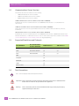
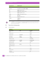
Supported Emulations and Protocols
Pion Emulation
Use this Emulation
for these Terminals
2392
1.4
TCP/IP Protocol
SNA Protocol
yes
3274
3277, 3278-2, 3278-2-E
yes
yes
5250
5251-11, 5555-B01
yes
yes
ANSI
yes
9010/TESS
yes
RF Modem
yes
HTML
yes
Remote sockets
yes
Text Conventions
Note: Notes highlight additional helpful information.
Important: These statements provide particularly important instructions or additional information that is critical to the operation of the equipment.
Warning:
4
These statements provide critical information that may prevent physical injury,
equipment damage or data loss.
Psion 9500 Series Communications Server Software User Manual
Chapter 1: Introduction
Emulations and Datastreams
1.5
Emulations and Datastreams
The Communications Server performs emulation conversion: the translation of data between the emulation
of the host computer and the emulation used by Psion devices.
The data that is sent from a host computer to a terminal, and the data which is returned to the host from
the terminal, is called a datastream.
Legacy Psion devices can accept only two types of datastream: TESS and ANSI. TESS (TEklogix Screen
Subsystem) is the native emulation used by the original Teklogix terminals. TESS features such as page
saving, passthru printing, and TSF/O are available. ANSI emulation is a standard type of datastream used by
wired VT-type terminals; these terminals are specified by the American National Standards Institute.
Some Psion mobile devices can accept HTML datastreams for display by a browser.
Other types of supported datastream provided by the host must be converted into TESS or HTML datastreams by the Communications Server.
The emulation software on the Communications Server can accept IBM-5250, IBM-3270, HP2392, and
HTML datastreams from host computers, and can convert them to and from TESS. The Communications
Server caches and compresses information when creating TESS datastreams to optimize performance. This
is most useful when transmitting across low bandwidth connections using narrow band radios.
The emulation software can also convert IBM-5250 and IBM-3270 datastreams to HTML datastreams, so
that they may be viewed through a web browser on the mobile device. The Communications Server does
not cache or compress HTML datastreams.
ANSI datastreams from host computers are not converted by the Communications Server before being
sent to the mobile devices. The Communications Server can, however, cache and compress ANSI datastreams to conserve bandwidth on a narrow band radio network.
Some hosts may have Psion handler or SDK software. This software runs on the host and communicates
directly with the host applications. Handlers and SDKs provide TESS datastreams which are compatible
with Psion mobile devices.
Psion 9500 Series Communications Server Software User Manual
5
Chapter 1: Introduction
Number of Connections
1.6
Number of Connections
Maximum number of mobile devices
Maximum number of base stations
Maximum number of hosts
6
S900, SW9500, and SW9510
S900L, SW9500L, and SW9510L
3840
50
254
254
16
16
Psion 9500 Series Communications Server Software User Manual
2
ADMINISTERING THE
COMMUNICATIONS
SERVER
ADMINISTERING THE COMMUNICATIONS SERVER
2.1
2.2
2.3
2
Accessing the Communications Server Browser Interface .
Accessing Windows Desktop . . . . . . . . . . . . . . . . . .
2.2.1 Stopping the Communications Server . . . . . . .
2.2.2 Restarting the Communications Server . . . . . .
2.2.3 Reading Event Log Entries. . . . . . . . . . . . . .
Accessing the Debug Console. . . . . . . . . . . . . . . . . .
.
.
.
.
.
.
.
.
.
.
.
.
.
.
.
.
.
.
.
.
.
.
.
.
.
.
.
.
.
.
.
.
.
.
.
.
.
.
.
.
.
.
.
.
.
.
.
.
.
.
.
.
.
.
.
.
.
.
.
.
.
.
.
.
.
.
.
.
.
.
.
.
.
.
.
.
.
.
.
.
.
.
.
.
.
.
.
.
.
.
.
.
.
.
.
.
.
.
.
.
.
.
.
.
.
.
.
.
.
.
.
.
.
.
.
.
.
.
.
.
.
.
.
.
.
.
.
.
.
.
.
.
.
.
.
.
.
.
.
.
.
.
.
.
.
.
.
.
.
.
.
.
.
.
.
.
.
.
.
.
.
.
.
.
.
.
.
.
.
.
.
.
.
.
.
.
.
.
.
.
.
.
.
.
.
.
.9
.9
.9
.9
.9
10
Psion 9500 Series Communications Server Software User Manual
7
Chapter 2: Administering The Communications Server
Accessing the Communications Server Browser Interface
2.1
Accessing the Communications Server Browser Interface
The Communications Server is configured through a browser interface.
Connecting locally
Use the following:
http://localhost:8008/
Connecting remotely
Use the following:
http://<IP address>:8008/
Where: <IP address> is the IP address of the computer running the Communications Server.
2.2
Accessing Windows Desktop
The Communications Server Software runs as a service under Windows.
The Communications Server Software automatically starts running when the computer starts or restarts.
Connecting remotely
If Remote Desktop access is enabled on the computer where Communications Server is installed you can
connect to it remotely.
2.2.1
Stopping the Communications Server
To stop the Communications Server Software do the following:
1.
2.
3.
2.2.2
In Control Panel select Services from the Administrative Tools menu.
Select CommServer Watchdog.
Select Stop.
Restarting the Communications Server
To restart the Communications Server Software without restarting the hardware do the following:
1.
2.
3.
2.2.3
In Control Panel select Services from the Administrative Tools menu.
Select CommServer Watchdog.
Select Restart.
Reading Event Log Entries
The Communications Server logs events that can be viewed with the Windows Event Viewer. The following
events are logged:
•
•
•
•
•
The watchdog task is started.
The watchdog restarts another task from crash or exit, or from checkpoint failure or timeout.
The user manually starts, terminates, or restarts a process (through the watchdog).
There is a change of redundancy status for the Communications Server: secondary to primary.
The Communications Server starts up as primary, or secondary.
View the logged events
1. In Control Panel, select Event Viewer from the Administrative Tools menu.
2. Select Application events.
3. To view more information on a selected event, double-click the entry for the event.
Psion 9500 Series Communications Server Software User Manual
9
Chapter 2: Administering The Communications Server
Accessing the Debug Console
2.3
Accessing the Debug Console
The Communications Server provides a text mode debug console. By default no username is needed to
open this console; however, the Communications Server may be configured to require a username and
password. For information on setting a username and password see User Screen on page 149. To make the
username and password required see Enable Telnet User Authentication on page 149.
Connecting locally
Use the following:
Telnet://localhost 9523
Connecting remotely
Use the following:
Telnet://<IP address> 9523
Where: <IP address> is the IP address of the computer running the Communications Server.
Using the debug console
You should only use this console with the help of Psion support staff.
10
Psion 9500 Series Communications Server Software User Manual
3
3274/TELNET HOST
CONFIGURATION
3274/TELNET HOST CONFIGURATION
3.1
3.2
3.3
3.4
3.5
3.6
3
Overview . . . . . . . . . . . . . . . . . . . . . . .
General Host Options Screen . . . . . . . . . . .
3274 Emulation Options Screen . . . . . . . . .
3.3.1
3274 Options . . . . . . . . . . . . . . .
3.3.2
TESS Options . . . . . . . . . . . . . .
3.3.3
HTML/HTTP Options . . . . . . . . . .
3274 Telnet Protocol Options Screen . . . . . .
3.4.1
3274 Telnet Terminal Naming Screen
3274 Function Key Mappings Screen. . . . . . .
Typical Host Configuration . . . . . . . . . . . .
3.6.1
Line Description . . . . . . . . . . . . .
3.6.2
Controller Description . . . . . . . . .
3.6.3
TCP/IP Link. . . . . . . . . . . . . . . .
.
.
.
.
.
.
.
.
.
.
.
.
.
.
.
.
.
.
.
.
.
.
.
.
.
.
.
.
.
.
.
.
.
.
.
.
.
.
.
.
.
.
.
.
.
.
.
.
.
.
.
.
.
.
.
.
.
.
.
.
.
.
.
.
.
.
.
.
.
.
.
.
.
.
.
.
.
.
.
.
.
.
.
.
.
.
.
.
.
.
.
.
.
.
.
.
.
.
.
.
.
.
.
.
.
.
.
.
.
.
.
.
.
.
.
.
.
.
.
.
.
.
.
.
.
.
.
.
.
.
.
.
.
.
.
.
.
.
.
.
.
.
.
.
.
.
.
.
.
.
.
.
.
.
.
.
.
.
.
.
.
.
.
.
.
.
.
.
.
.
.
.
.
.
.
.
.
.
.
.
.
.
.
.
.
.
.
.
.
.
.
.
.
.
.
.
.
.
.
.
.
.
.
.
.
.
.
.
.
.
.
.
.
.
.
.
.
.
.
.
.
.
.
.
.
.
.
.
.
.
.
.
.
.
.
.
.
.
.
.
.
.
.
.
.
.
.
.
.
.
.
.
.
.
.
.
.
.
.
.
.
.
.
.
.
.
.
.
.
.
.
.
.
.
.
.
.
.
.
.
.
.
.
.
.
.
.
.
.
.
.
.
.
.
.
.
.
.
.
.
.
.
.
.
.
.
.
.
.
.
.
.
.
.
.
.
.
.
.
.
.
.
.
.
.
.
.
.
.
.
.
.
.
.
.
.
.
.
.
.
.
.
.
.
.
.
.
.
.
.
.
.
.
.
.
.
.
.
.
.
.
.
.
.
.
.
.
.
.
.
.
.
.
.
.
.
.
.
.
.
.
.
.
.
.
.
.
.
.
.
.
.
.
.
.
.
.
.
.
.
.
.
.
.
.
.
.
.
.
.
.
.
.
.
.
.
.
.
.
.
.
.
.
.
.
.
.
.
.
.
.
.
.
.
.
.
.
.
.
.
.
.
.
.
.
.
.
.
.
.
.
.
.
.
.
.
.
.
.
.
.
.
.
.
.
.
.
.
.
.
.
.
.
.
.
.
.
.
.
.
.
.
.
.
.
.
.
.
.
.
.
.
.
.
13
13
14
14
14
21
21
23
23
24
24
25
25
Psion 9500 Series Communications Server Software User Manual
11
Chapter 3: 3274/Telnet Host Configuration
Overview
3.1
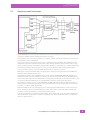
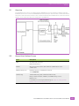
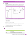
Overview
The Communications Server can emulate an IBM 3274 controller connected to a number of IBM terminals.
The emulation software inside the Communications Server converts the 3274 data transparently to and
from TESS or HTTP data which is then sent to and from the Psion devices. The connection between the
Communications Server and its base stations, access points, and devices is transparent to the IBM host.
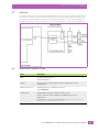
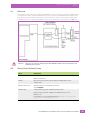
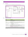
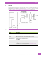
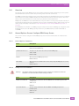
3.2
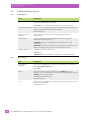
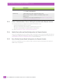
General Host Options Screen
Field
Description
Name
The unique name of the host.
Default: Unnamed Host
Enabled
When selected the host task is started when the Communications Server
software starts.
Emulation and protocol
Emulation and protocol combination for this host.
Select: 3274/Telnet
Terminal range
Terminal number range that communicates with this host.
Range: 1 to 3840. For S900L, SW9500L, and SW9510L range is 1 to 50.
Default: 1 to 32
For information on selecting the terminal range see Chapter 21: “Setting Terminal
Numbers on the General Host Options Screen”
Psion 9500 Series Communications Server Software User Manual
13
Chapter 3: 3274/Telnet Host Configuration
3274 Emulation Options Screen
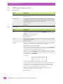
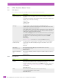
3.3
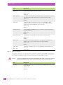
3274 Emulation Options Screen
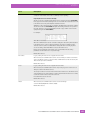
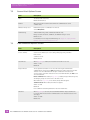
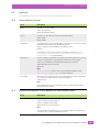
3.3.1
3274 Options
Field
Description
Is Host Fujitsu
When selected the Communications Server sends data in Fujitsu format.
The standard IBM formatting codes (for start of field, setting buffers, etc.) are replaced
by the codes used by Fujitsu host computers.
Default: Not selected.
Use International EBCDIC
When selected the Communications Server uses the international EBCDIC character
set, the positions of the ! and ] characters are swopped.
Default: Not selected.
Allow null character in
fixed field
When selected, empty fields show video attributes properly when using
3274 emulation.
Default: Not selected.
Treat EraseWrite NOP as
Write NOP
When selected, during PASSTHRU printing of multiple screens, buffered print data is
not erased.
Default: Selected.
Terminal Protocol
The protocol used for the connection between the mobile devices and the
Communications Server. Options are:
TESS/BCM: This uses the Communications Server data caching, and page
saving, features.
HTML/HTTP: This uses the Communication Server HTTP server. The browser on the
mobile devices must connect to port 80 on the Communications Server.
Default: TESS/BCM
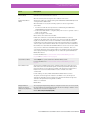
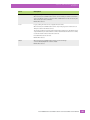
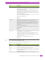
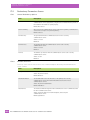
3.3.2
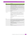
TESS Options
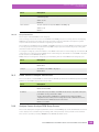
Field
Description
Alarm
When selected, mobile devices beep when the word ALARM appears on the
application screen, in the location specified by the Command Region setting. The word
ALARM should be a display-only field.
Command Region must also be set.
Default: Not selected.
For more information see Command Region on page 20.
Clear
When selected, the Communications Server creates an empty entry field for an entry
field that is filled with spaces.
Default: Not selected.
14
Psion 9500 Series Communications Server Software User Manual
Chapter 3: 3274/Telnet Host Configuration
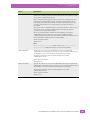
TESS Options
Field
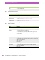
Description
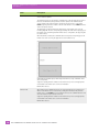
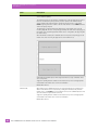
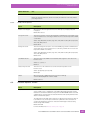
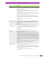
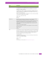
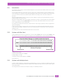
Passthru
When selected, the Communications Server allows the host to send data directly to the
serial port of the mobile device. This is commonly used for printing.
Preparing Host Screens for Pass-Through:
On the screen to be sent through the mobile device serial port, the word PASSTHRU
has to appear on the first line, starting in the second column. The actual data to be sent
to the mobile device may start anywhere below the first line.
Attributes occupy a position in the screen buffer. An attribute placed between column 2
and the end of the word PASSTHRU will push all following characters one position to
the right. Therefore, any required attributes should occupy column 1 of the first line
(just preceding the word PASSTHRU).
For example:
where @ is an attribute.
When the Communications Server is finished sending the data to the printer attached
to the mobile device, it sends a packet containing only a Record Separator (0x1e)
character to the host. The host must wait for this packet before sending any more
screens (including other PASSTHRU screens) to the mobile device.
Refer to the user manual for the mobile device for information about setting
parameters on the mobile device for pass-through.
Default: Not selected.
Procedures
Legacy setting. The last device to support this is the 7030.
When selected, the Communications Server can send TESS procedures to the mobile
devices. A TESS procedure is a group of TESS commands that can be executed by the
TESS execute procedure command.
Default: Not selected.
Local
Legacy setting. The last device to support this is the 7030.
When selected, the Communications Server can provide pages to be loaded as local
TESS procedures in the mobile devices.
The local procedures are selected from a menu on the mobile device. The mobile device
can perform these procedures when it is offline. Later when the mobile device is online,
it sends the results of these functions to the host.
Procedures must also be selected.
Default: Not selected.
TSF/O
When selected, the Communications Server uses Psion Teklogix
Screen-Formatter/Optimizer software (TSF/O).
Default: Not selected.
Psion 9500 Series Communications Server Software User Manual
15
Chapter 3: 3274/Telnet Host Configuration
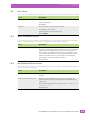
TESS Options
Field
Description
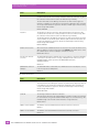
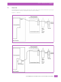
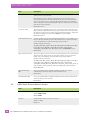
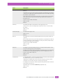
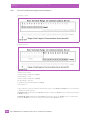
Host Print
When selected, an application can send data to the display on the mobile device as well
as to its attached printer.
The text that is passed to the printer is formatted into a 24 x 80 application screen. If
the host can initiate the print operation, the text is printed. The Communications
Server identifies the additional text as a print page by the presence of the string
PRINT beginning in the 2nd column of line 13 on the 24 x 80 screen. PRINT should be
defined as display-only text.
The print page is positioned below the display page of the mobile device (see the
following diagram). The size of the print page is always the same as the display page of
the mobile device (assuming that in the mobile device configuration, the page length is
less than 12 lines).
When Host Print is enabled, the Communications Server passes the print page to the
mobile device after receiving the application screen from the host.
Unlike with the Passthru option, when using Host Print no escape commands can be
sent to the printer.
Support for printing must be enabled on the mobile device; refer to the appropriate
user manual for the mobile device for more information
Default: Not selected.
Remote Print
When enabled, the Communications Server sends the print page to a mobile device
whenever the mobile device requests it (by sending the F17 function key from the
mobile device, or the PRINT key on older mobile devices). The Communications Server
sends the function response back to the host.
Support for printing must be enabled on the mobile device; refer to the appropriate
user manual for the mobile device for more information.
Default: Not selected.
16
Psion 9500 Series Communications Server Software User Manual
Chapter 3: 3274/Telnet Host Configuration
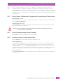
TESS Options
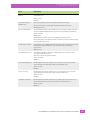
Field
Description
Pages
The number of host screens (or pages) stored on the mobile device.
The Communications Server maintains an image of each page stored on the mobile
device. After receiving an application screen, the Communications Server tries to
match the screen with a stored page.
If a similar page is already in the mobile device memory, the Communications Server
instructs the mobile device to re-display its copy of the page; only the necessary
changes are sent from the Communications Server. If no match is found, the complete
page is sent to the mobile device.
There is a corresponding parameter on the mobile device itself, and the actual number
of saved pages is the smaller of the two values.
A value of 1 (one) disables this feature.
Values: 1 to 79
Default: 8
Transmit Line
When enabled, all modified data on the mobile device is automatically transmitted
when the operator enters data into an entry field on or above this line.
The value in this text box specifies the line on the screen which is designated as the
transmit line. The last entry field on or above the transmit line on the screen is
identified as the field which will cause all modified data to be sent to the host. Any
entry fields that exist on lines below the transmit line will not cause the screen to
be transmitted.
A value of 0 (zero) disables this feature.
A value of 24 causes the last entry field on each application screen to be defined as
transmit-upon-entry.
Values: 0 to 24
Default: 0
AIAG
The decimal value of the special character (ASCII) used to tag a field to use AIAG mode.
When barcode data is entered on a mobile device, the mobile device searches for AIAG
fields on the current page. These fields can accept the special barcode data. The data
preloaded into the AIAG field by the application program determines whether a
barcode is accepted. The format of the preloaded data is:
<mode><AIAG prefix>
The application program distinguishes an entry field as AIAG by preceding the entry
field with this special AIAG character.
A value of 0 (zero) disables this feature.
Values: 0 to 255
Default: 0
For the AIAG mode character table see AIAG Mode Values on page 20.
Psion 9500 Series Communications Server Software User Manual
17
Chapter 3: 3274/Telnet Host Configuration
TESS Options
Field
Description
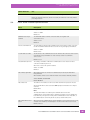
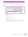
Visible Match Character
The decimal value of the special character (ASCII) used to tag a field to use visible
match mode.
With field matching, the host computer preloads data into an entry field. Now the
mobile device operator can make an entry that matches this preloaded data. For visible
match fields, the preloaded data is displayed in the entry field on the mobile device.
The application program distinguishes an entry field as a match field by preceding it
with a special character.
The special character is entered as the decimal character code for one of the first 127
ASCII characters.
For example, assume that the > character (ASCII decimal character code 62) is defined
for visible match fields. This character must immediately precede the entry field:
Part #>_______
The field: Part #> includes the character > and is followed by the part number entry
field on the screen. If any other character was chosen as the last character of the text,
the entry field would not be a match field.
The preloaded data sent to a mobile device may consist of the exact characters, special
match characters or a combination of the two.
For example, suppose you wish to preload an entry field with a part number. If the exact
part number is known, you may preload the field with that part number. If more
flexibility is required, and part numbers always begin with two alphabetic characters
followed by a hyphen character and four digits, then the match string for the field
could be: &&–####.
If an entry is different from the preloaded data, the entry is displayed, the mobile
device beeps and the cursor is in the first position of the match field.
Now either another entry in the match field can be made, or the cursor can be moved
to a new field. When an entry (even if it does not match the host preloaded data) is
made in a match field, this entry is sent to the host as part of the modified data from
the mobile device during the next transmission.
A value of 0 (zero) disables this match field feature.
Values: 0 to 255
Default: 0
For the Psion match characters see Match Characters on page 20.
Hidden Match Character
The decimal value of the special character (ASCII) used to tag a field to use hidden
match mode.
A special character is used to mark Hidden Match fields in a TESS screen. This
character precedes the field contents of the Hidden Match field. In hidden match fields,
as opposed to visible match fields, the preloaded entry is not displayed in the entry
field on the mobile device).
A value of 0 (zero) disables this feature.
Values: 0 to 255
Default: 0
For the Psion match characters see Match Characters on page 20.
18
Psion 9500 Series Communications Server Software User Manual
Chapter 3: 3274/Telnet Host Configuration
TESS Options
Field
Description
Serial I/O
The decimal value of the special character (ASCII) used to tag a field to use serial
I/O mode.
Serial I/O fields are special entry and fixed fields that accept input from, and output to,
a serial port. The application program distinguishes this field as Serial I/O by preceding
the field with a special character.
If this character precedes a fixed field, the data is sent to the serial port of the mobile
device. If it precedes an entry field, the field accepts data from the serial port of
the mobile device.
A value of 0 (zero) disables this feature.
Values: 0 to 255
Default: 0
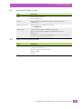
Print Line
The starting line number of the print page on the application screen.
A value of 1 (one) causes the display page to be printed. A value of 0 (zero) disables
this feature.
Values: 0 to 24
Default: 0
Print Form Length
The printer form length, in lines.
Values: 0 to 24
Default: 0
Barcode
The decimal value of the special character (ASCII) used to tag a field to use barcode
only mode.
Barcode-input-only fields are special entry fields that only accept input from a barcode
reader. The application program distinguishes an entry field as barcode-input-only by
preceding the field with a special character.
A value of 0 (zero) disables this feature.
Values: 0 to 255
Default: 0
Entry Line
The number of the first line displayed if there is no entry field above this line on the
screen and if an entry field is at or below this line.
The Entry Line parameter allows an automatic offset within the host screen. Normally,
Psion mobile devices only display the upper left corner of the application screen
because of their smaller display size.
Values: 0 to 24
Default: 0
Field Overhead
The maximum number of characters allowed between two fixed fields which still allows
the Communications Server to join them into one field.
Sometimes the Communications Server will join two adjacent fixed fields and then
send them as one field. This reduces the overhead on the radio link.
For example, if two fields were 4 characters apart and this parameter was 5, then these
fields would be joined into one.
This feature affects fields with the Normal display attribute only.
Values: 0 to 80
Default: 5
Psion 9500 Series Communications Server Software User Manual
19
Chapter 3: 3274/Telnet Host Configuration
TESS Options
Field
Description
Command Region
These two pairs of text boxes define a region of the host screen which the
Communications Server examines for the presence of reserved commands. The first
text box of each pair contains the row number; the second contains the
column number.
These four numbers represent the row and column addresses of the upper left corner
and the lower right corner of the command region. To define the last two lines of the
host screen as the command region, for example, enter 23, 1 - 24, 80
The only commands supported in the command region are ALARM and FONT:
• When the word ALARM is placed anywhere within the command region, the
Communications Server sends a TESS beep command to the mobile device.
• When the word FONT is placed anywhere within the command region, and
followed by a number (the font code), the Communications Server sends the
appropriate TESS Change Font command to the mobile device.
For font codes see Font Code List for Open TekTerm on IngenuityWorking.
Font codes are only required for versions of OTT before version D.
Rows: 0to 24
Columns: 0to 80
Default: 0, 0 - 0, 0
AIAG Mode Values
The mode character is derived by starting with the decimal value 48—ASCII character 0 (zero)—and adding
the appropriate value from the table below.
Code
Description
1
Prevent the AIAG prefix from being displayed.
2
Prevent the AIAG prefix from being sent to the host.
4
Cause a transmission to the host when all AIAG fields with this mode set are filled. The
transmission is sent by a Function 0 (F0) code.
8
Allow overwriting of previously entered data.
16
Start the search for a matching AIAG field at the current cursor position. Otherwise, the
cursor starts at the top of the page.
For example, the @ symbol is used to apply the cursor matching function, since adding 16 to 48 results in
decimal value 64, which is the ASCII value for the character @.
Match Characters
20
Match Character
Use
#
Match a number
&
Match a letter (either case)
^
Match an upper case letter
_
Match a lower case letter
|
Match an alphanumeric character
"
Match a letter, number or space
?
Match a punctuation character
'
Match any character
Psion 9500 Series Communications Server Software User Manual
Chapter 3: 3274/Telnet Host Configuration
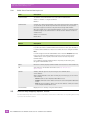
HTML/HTTP Options
3.3.3
Match Character
Use
:
Match all character positions in the field with the preceding character
;
Match any remaining characters, but not necessarily the remainder of the field, with the
preceding character
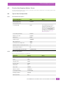
HTML/HTTP Options
Field
Description
Foreground Colour
This is the foreground colour for the text that the Communications Server HTTP server
sends to mobile devices connecting via HTTP. The choices are the 16 predefined HTML
colour names.
Values: Aqua, Black, Blue, Fuchsia, Gray, Green, Lime, Maroon, Navy, Olive, Purple, Red,
Silver, Teal, White, Yellow
Default: Black
Background Colour
This is the background colour, the colour of the HTML page, that the Communications
Server HTTP server sends to mobile devices connecting via HTTP. The choices are the
16 predefined HTML colour names.
Values: Aqua, Black, Blue, Fuchsia, Gray, Green, Lime, Maroon, Navy, Olive, Purple, Red,
Silver, Teal, White, Yellow
Default: Silver
User Data Font Size
This is the value for the HTML font size attribute that is applied to user data on the
browser screen.
Values: 1, 2, 3, 4, 5, 6, 7
Default: 3
Function Key Font Size
This is the size of the font that is used on the function key buttons on the
browser screen.
Values: 4pt, 6pt, 8pt, 10pt, 12pt, 14pt
Default: 8pt
TSF/O
When selected the Communications Server uses Psion Teklogix
Screen-Formatter/Optimizer software (TSF/O).
Default: Selected.
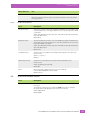
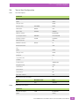
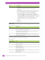
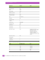
3.4
3274 Telnet Protocol Options Screen
Field
Description
Terminal Type
The type of terminal to be emulated by the Communications Server.
Values: IBM-2378-2, IBM-3278-2-E
Default: IBM-2378-2
Host Port
The port number on the host for this connection.
Values: 1 to 32767
Default: 23
Maximum Sessions per
Terminal
The maximum number of Telnet connections that can originate from
each mobile device.
Values: 1 to 127
Default: 4
Psion 9500 Series Communications Server Software User Manual
21
Chapter 3: 3274/Telnet Host Configuration
3274 Telnet Protocol Options Screen
Field
Description
First Local Terminal Port
The port number from which the Communications Server makes a Telnet connection
for the first terminal. Additional Telnet sessions are assigned higher port numbers.
Values: 1 to 32767
Default: 10000
Local IP Address to Bind
The IP address of the Communications Server interface that connects to this host. It is
used with the local port numbers to create a unique socket for each mobile
device session.
Default: 0.0.0.0
First Terminal Listen Port
The lowest port number on which the Communications Server listens for Telnet
connections initiated by the host.
When set to 0 (zero) this option is disabled.
Values: 0 to 32767
Default: 0
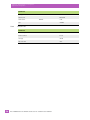
Actively Negotiate with
Host
When selected, the Communications Server performs advanced negotiations with the
host during Telnet connection.
Default: Not selected.
Configure LU names
When selected, the Communications Server requests LU names when initiating the
Telnet connection with this 3274 host. Terminal names can be configured on the 3274
Terminal Naming screen.
Default: Not selected.
For more information see Section 3.4.1 3274 Telnet Terminal Naming Screen on
page 23.
LU Name Prefix
The LU prefix to be added to terminal names when Configure LU names is set. This
prefix can be up to five alphanumeric characters.
Default: None.
Send IAC Interrupt
Process as a System
Request
When selected, the Communications Server sends the IAC Interrupt Process request to
the host as a 3274 System Request.
Send IAC Break as a
Attention Key
When selected, the Communications Server sends the IAC Break request to the host as
a 3274 Attention Key.
Default: Not selected.
Default: Not selected.
Auto-telnet/login Enable
When enabled, the host connection is automatically selected by the Auto-telnet
Host parameter.
When disabled, Telnet sessions from the mobile devices must be manually initiated.
Values: DISABLE, AUTO-TELNET
Default: DISABLE
Auto-telnet Host
The name or the IP address of the host to which auto-Telnet requests are directed.
Any host name which can be used at the TCP> prompt on the mobile device may be
used here.
Default: None.
Note:
The host name must be resolvable by the Communications Server: The
Communications Server must be able to obtain an IP address for it. For example, the
host name may correspond to an entry in the Communications Server host table, or
the Communications Server may be able to query a domain name server.
22
Psion 9500 Series Communications Server Software User Manual
Chapter 3: 3274/Telnet Host Configuration
3274 Telnet Terminal Naming Screen
Field
Description
Auto-telnet Without User
Action
When selected, the Communications Server attempts to connect to the host as soon as
a mobile device initializes, and it attempts to reconnect if the Telnet session closes.
Default: Selected.
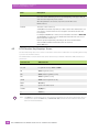
3.4.1
3274 Telnet Terminal Naming Screen
This screen opens when Configure LU names is clicked on the 3274 Telnet Protocol Options Screen.
Field
Terminal number
Description
The number of the terminal which has the name in Terminal name.
Values: 1 to <number of configured terminals>
Default: 1
Terminal name
An LU name for the terminal. This name can contain no more than 10
alphanumeric characters.
If no terminal name is specified here for a terminal, the Communications Server
appends the terminal number (as five digits, with leading zeros if necessary) to the LU
Prefix to create the full LU terminal name.
Values: 1 to 10 characters.
Default: None.
Buttons
Button
Description
Show/Set
Displays the LU name associated with the terminal number.
If you have just entered a terminal number and LU name, press this button to add the
terminal number and LU name to the list of configured terminals.
Delete
Deletes the currently-displayed terminal number and LU name from the list.
OK
Saves changes to the database. When it is pressed, the Communications Server
displays a confirmation screen. Press OK in this screen to save the changes and exit to
the 3274 Telnet Protocol Options Screen.
Validate
Validates, with the option to save, the changes to the Communications
Server database.
On the Validation Results screen, after reviewing any error messages, you can click one
of the following:
• Cancel: Returns to the 3274 Telnet Terminal Naming Screen.
• Commit: Commits the entire database and returns to the Configuration Main
Menu screen.
• Undo: Discards all database changes since the last database commit, and returns
to the Configuration Main Menu screen.
Show Terminals
3.5
Displays the list of currently-configured terminal names.
3274 Function Key Mappings Screen
Use the function key list boxes to select a code that is sent to the host when the corresponding function key
is pressed on the mobile device.
The 3274 emulator converts the mobile device function keys to Attention Identifier (AID) characters, as
shown here:
Psion 9500 Series Communications Server Software User Manual
23
Chapter 3: 3274/Telnet Host Configuration
Typical Host Configuration
Selected code
AID Character
ENTER
<Enter> key
F1 to F24
Program Function keys <PF1> to <PF24>
PA1
<PA1> Program Access key
PA2
<PA2> (CNCL) Program Access key
PA3
<PA3> Program Access key
CLEAR
<PA4> (Clear) Program Access key
RESET
<Reset> key
SESS
Opens a new Telnet session
SYSREQ
<SysRq> key
U
<Test> key
Note: The Enter key on the mobile device only triggers a transmission to the host if the mobile device is
configured to operate the Enter key as function 0 (F0). Consult the user manual for the mobile
device for more information.
3.6
Typical Host Configuration
3.6.1
Line Description
Parameter
Line description
LIND
ENETLINE
Option
*BASIC
Category of line
*ELAN
Resource name
RSRCNAME
LIN021
Online at IPL
ONLINE
*YES
Vary on wait
VRYWAIT
*NOWAIT
Network controller
RFCTRLENET
Local adapter address
ADPTADR
08005AB7C3FD
Exchange identifier
EXCHID
05629A5A
Ethernet standard
Maximum controllers
*ALL
MAXCTL
Error threshold level
40
*OFF
Text
24
Option
*APPN
Category of line
*ELAN
Link speed
10M
Cost/connect time
0
Psion 9500 Series Communications Server Software User Manual
Chapter 3: 3274/Telnet Host Configuration
Typical Host Configuration
Parameter
Cost/byte
0
Security for line
*NONSECURE
Propagation delay
*LAN
User-defined 1
128
User-defined 2
128
User-defined 2
128
Autocreate controller
*NO
Source Service Access Points
3.6.2
SSAP
Maximum Frame
Type
AA
1496
*NONSNA
CTRD
RFCTRLENET
Controller Description
Parameter
Controller description
Option
*BASIC
Category of controller
*NET
Attached line
ENETLINE
Online at IPL
ONLINE
Text
3.6.3
*YES
*BLANK
TCP/IP Link
Parameter
Line description
DEVD
ENETLINE
Internet address
50.0.1.1
Link type
*ELAN
Auto start link
*YES
Psion 9500 Series Communications Server Software User Manual
25
4
3274/SNA HOST
CONFIGURATION
3274/SNA HOST CONFIGURATION
4.1
4.2
4.3
4.4
4.5
4.6
Overview . . . . . . . . . . . . . . . . .
General Host Options Screen . . . . .
3274 Emulation Options Screen . . .
4.3.1
3274 Options . . . . . . . . .
4.3.2
TESS Options . . . . . . . .
4.3.3
HTML/HTTP Options . . . .
3274 SNA Protocol Screen . . . . . .
3274 Function Key Mappings Screen.
Typical Host Configuration . . . . . .
4.6.1
Definition in VTAM . . . . .
4
.
.
.
.
.
.
.
.
.
.
.
.
.
.
.
.
.
.
.
.
.
.
.
.
.
.
.
.
.
.
.
.
.
.
.
.
.
.
.
.
.
.
.
.
.
.
.
.
.
.
.
.
.
.
.
.
.
.
.
.
.
.
.
.
.
.
.
.
.
.
.
.
.
.
.
.
.
.
.
.
.
.
.
.
.
.
.
.
.
.
.
.
.
.
.
.
.
.
.
.
.
.
.
.
.
.
.
.
.
.
.
.
.
.
.
.
.
.
.
.
.
.
.
.
.
.
.
.
.
.
.
.
.
.
.
.
.
.
.
.
.
.
.
.
.
.
.
.
.
.
.
.
.
.
.
.
.
.
.
.
.
.
.
.
.
.
.
.
.
.
.
.
.
.
.
.
.
.
.
.
.
.
.
.
.
.
.
.
.
.
.
.
.
.
.
.
.
.
.
.
.
.
.
.
.
.
.
.
.
.
.
.
.
.
.
.
.
.
.
.
.
.
.
.
.
.
.
.
.
.
.
.
.
.
.
.
.
.
.
.
.
.
.
.
.
.
.
.
.
.
.
.
.
.
.
.
.
.
.
.
.
.
.
.
.
.
.
.
.
.
.
.
.
.
.
.
.
.
.
.
.
.
.
.
.
.
.
.
.
.
.
.
.
.
.
.
.
.
.
.
.
.
.
.
.
.
.
.
.
.
.
.
.
.
.
.
.
.
.
.
.
.
.
.
.
.
.
.
.
.
.
.
.
.
.
.
.
.
.
.
.
.
.
.
.
.
.
.
.
.
.
.
.
.
.
.
.
.
.
.
.
.
.
.
.
.
.
.
.
.
.
.
.
.
.
.
.
.
.
.
.
.
.
.
.
.
.
.
.
.
.
.
.
.
.
.
.
.
.
.
.
.
.
.
.
.
.
.
.
.
.
.
.
.
.
.
.
.
.
.
.
.
.
.
.
.
.
.
.
.
.
.
.
.
.
.
.
.
.
.
29
29
30
30
30
37
37
38
39
39
Psion 9500 Series Communications Server Software User Manual
27
Chapter 4: 3274/SNA Host Configuration
Overview
4.1
Overview
The Communications Server can emulate an IBM 3274 controller connected to a number of IBM terminals.
The emulation software inside the Communications Server converts the 3274 data transparently to and
from TESS or HTTP data which is then sent to and from the devices. The connection between the Communications Server and its base stations, access points, and devices is transparent to the IBM host.
Warning:
4.2
When you are using the SNA protocol, IBM PCOMM software must be installed on the
Communications Server.
General Host Options Screen
Field
Description
Name
The unique name of the host.
Default: Unnamed Host
Enabled
When selected the host task is started when the Communications Server
software starts.
Emulation and protocol
Emulation and protocol combination for this host.
Select: 3274/SNA
Terminal range
Terminal number range that communicates with this host.
Range: 1 to 3840. For S900L, SW9500L, and SW9510L range is 1 to 50.
Default: 1 to 32
For information on selecting the terminal range see Chapter 21: “Setting Terminal
Numbers on the General Host Options Screen”
Psion 9500 Series Communications Server Software User Manual
29
Chapter 4: 3274/SNA Host Configuration
3274 Emulation Options Screen
4.3
3274 Emulation Options Screen
4.3.1
3274 Options
Field
Description
Is Host Fujitsu
When selected the Communications Server sends data in Fujitsu format.
The standard IBM formatting codes (for start of field, setting buffers, etc.) are replaced
by the codes used by Fujitsu host computers.
Default: Not selected.
Use International EBCDIC
When selected the Communications Server uses the international EBCDIC character
set, the positions of the ! and ] characters are swopped.
Default: Not selected.
Allow null character in
fixed field
When selected, empty fields show video attributes properly when using
3274 emulation.
Default: Not selected.
Treat EraseWrite NOP as
Write NOP
When selected, during PASSTHRU printing of multiple screens, buffered print data is
not erased.
Default: Selected.
Terminal Protocol
The protocol used for the connection between the mobile devices and the
Communications Server. Options are:
TESS/BCM: This uses the Communications Server data caching, and page
saving, features.
HTML/HTTP: This uses the Communication Server HTTP server. The browser on the
mobile devices must connect to port 80 on the Communications Server.
Default: TESS/BCM
4.3.2
TESS Options
Field
Description
Alarm
When selected, mobile devices beep when the word ALARM appears on the
application screen, in the location specified by the Command Region setting. The word
ALARM should be a display-only field.
Command Region must also be set.
Default: Not selected.
For more information see Command Region on page 36.
Clear
When selected, the Communications Server creates an empty entry field for an entry
field that is filled with spaces.
Default: Not selected.
30
Psion 9500 Series Communications Server Software User Manual
Chapter 4: 3274/SNA Host Configuration
TESS Options
Field
Description
Passthru
When selected, the Communications Server allows the host to send data directly to the
serial port of the mobile device. This is commonly used for printing.
Preparing Host Screens for Pass-Through:
On the screen to be sent through the mobile device serial port, the word PASSTHRU
has to appear on the first line, starting in the second column. The actual data to be sent
to the mobile device may start anywhere below the first line.
Attributes occupy a position in the screen buffer. An attribute placed between column 2
and the end of the word PASSTHRU will push all following characters one position to
the right. Therefore, any required attributes should occupy column 1 of the first line
(just preceding the word PASSTHRU).
For example:
where @ is an attribute.
When the Communications Server is finished sending the data to the printer attached
to the mobile device, it sends a packet containing only a Record Separator (0x1e)
character to the host. The host must wait for this packet before sending any more
screens (including other PASSTHRU screens) to the mobile device.
Refer to the user manual for the mobile device for information about setting
parameters on the mobile device for pass-through.
Default: Not selected.
Procedures
Legacy setting. The last device to support this is the 7030.
When selected, the Communications Server can send TESS procedures to the mobile
devices. A TESS procedure is a group of TESS commands that can be executed by the
TESS execute procedure command.
Default: Not selected.
Local
Legacy setting. The last device to support this is the 7030.
When selected, the Communications Server can provide pages to be loaded as local
TESS procedures in the mobile devices.
The local procedures are selected from a menu on the mobile device. The mobile device
can perform these procedures when it is offline. Later when the mobile device is online,
it sends the results of these functions to the host.
Procedures must also be selected.
Default: Not selected.
TSF/O
When selected, the Communications Server uses Psion Teklogix
Screen-Formatter/Optimizer software (TSF/O).
Default: Not selected.
Psion 9500 Series Communications Server Software User Manual
31
Chapter 4: 3274/SNA Host Configuration
TESS Options
Field
Description
Host Print
When selected, an application can send data to the display on the mobile device as well
as to its attached printer.
The text that is passed to the printer is formatted into a 24 x 80 application screen. If
the host can initiate the print operation, the text is printed. The Communications
Server identifies the additional text as a print page by the presence of the string
PRINT beginning in the 2nd column of line 13 on the 24 x 80 screen. PRINT should be
defined as display-only text.
The print page is positioned below the display page of the mobile device (see the
following diagram). The size of the print page is always the same as the display page of
the mobile device (assuming that in the mobile device configuration, the page length is
less than 12 lines).
When Host Print is enabled, the Communications Server passes the print page to the
mobile device after receiving the application screen from the host.
Unlike with the Passthru option, when using Host Print no escape commands can be
sent to the printer.
Support for printing must be enabled on the mobile device; refer to the appropriate
user manual for the mobile device for more information
Default: Not selected.
Remote Print
When enabled, the Communications Server sends the print page to a mobile device
whenever the mobile device requests it (by sending the F17 function key from the
mobile device, or the PRINT key on older mobile devices). The Communications Server
sends the function response back to the host.
Support for printing must be enabled on the mobile device; refer to the appropriate
user manual for the mobile device for more information.
Default: Not selected.
32
Psion 9500 Series Communications Server Software User Manual
Chapter 4: 3274/SNA Host Configuration
TESS Options
Field
Description
Pages
The number of host screens (or pages) stored on the mobile device.
The Communications Server maintains an image of each page stored on the mobile
device. After receiving an application screen, the Communications Server tries to
match the screen with a stored page.
If a similar page is already in the mobile device memory, the Communications Server
instructs the mobile device to re-display its copy of the page; only the necessary
changes are sent from the Communications Server. If no match is found, the complete
page is sent to the mobile device.
There is a corresponding parameter on the mobile device itself, and the actual number
of saved pages is the smaller of the two values.
A value of 1 (one) disables this feature.
Values: 1 to 79
Default: 8
Transmit Line
When enabled, all modified data on the mobile device is automatically transmitted
when the operator enters data into an entry field on or above this line.
The value in this text box specifies the line on the screen which is designated as the
transmit line. The last entry field on or above the transmit line on the screen is
identified as the field which will cause all modified data to be sent to the host. Any
entry fields that exist on lines below the transmit line will not cause the screen to
be transmitted.
A value of 0 (zero) disables this feature.
A value of 24 causes the last entry field on each application screen to be defined as
transmit-upon-entry.
Values: 0 to 24
Default: 0
AIAG
The decimal value of the special character (ASCII) used to tag a field to use AIAG mode.
When barcode data is entered on a mobile device, the mobile device searches for AIAG
fields on the current page. These fields can accept the special barcode data. The data
preloaded into the AIAG field by the application program determines whether a
barcode is accepted. The format of the preloaded data is:
<mode><AIAG prefix>
The application program distinguishes an entry field as AIAG by preceding the entry
field with this special AIAG character.
A value of 0 (zero) disables this feature.
Values: 0 to 255
Default: 0
For the AIAG mode character table see AIAG Mode Values on page 36.
Psion 9500 Series Communications Server Software User Manual
33
Chapter 4: 3274/SNA Host Configuration
TESS Options
Field
Description
Visible Match Character
The decimal value of the special character (ASCII) used to tag a field to use visible
match mode.
With field matching, the host computer preloads data into an entry field. Now the
mobile device operator can make an entry that matches this preloaded data. For visible
match fields, the preloaded data is displayed in the entry field on the mobile device.
The application program distinguishes an entry field as a match field by preceding it
with a special character.
The special character is entered as the decimal character code for one of the first 127
ASCII characters.
For example, assume that the > character (ASCII decimal character code 62) is defined
for visible match fields. This character must immediately precede the entry field:
Part #>_______
The field: Part #> includes the character > and is followed by the part number entry
field on the screen. If any other character was chosen as the last character of the text,
the entry field would not be a match field.
The preloaded data sent to a mobile device may consist of the exact characters, special
match characters or a combination of the two.
For example, suppose you wish to preload an entry field with a part number. If the exact
part number is known, you may preload the field with that part number. If more
flexibility is required, and part numbers always begin with two alphabetic characters
followed by a hyphen character and four digits, then the match string for the field
could be: &&–####.
If an entry is different from the preloaded data, the entry is displayed, the mobile
device beeps and the cursor is in the first position of the match field.
Now either another entry in the match field can be made, or the cursor can be moved
to a new field. When an entry (even if it does not match the host preloaded data) is
made in a match field, this entry is sent to the host as part of the modified data from
the mobile device during the next transmission.
A value of 0 (zero) disables this match field feature.
Values: 0 to 255
Default: 0
For the Psion match characters see Match Characters on page 36.
Hidden Match Character
The decimal value of the special character (ASCII) used to tag a field to use hidden
match mode.
A special character is used to mark Hidden Match fields in a TESS screen. This
character precedes the field contents of the Hidden Match field. In hidden match fields,
as opposed to visible match fields, the preloaded entry is not displayed in the entry
field on the mobile device).
A value of 0 (zero) disables this feature.
Values: 0 to 255
Default: 0
For the Psion match characters see Match Characters on page 36.
34
Psion 9500 Series Communications Server Software User Manual
Chapter 4: 3274/SNA Host Configuration
TESS Options
Field
Description
Serial I/O
The decimal value of the special character (ASCII) used to tag a field to use serial
I/O mode.
Serial I/O fields are special entry and fixed fields that accept input from, and output to,
a serial port. The application program distinguishes this field as Serial I/O by preceding
the field with a special character.
If this character precedes a fixed field, the data is sent to the serial port of the mobile
device. If it precedes an entry field, the field accepts data from the serial port of
the mobile device.
A value of 0 (zero) disables this feature.
Values: 0 to 255
Default: 0
Print Line
The starting line number of the print page on the application screen.
A value of 1 (one) causes the display page to be printed. A value of 0 (zero) disables
this feature.
Values: 0 to 24
Default: 0
Print Form Length
The printer form length, in lines.
Values: 0 to 24
Default: 0
Barcode
The decimal value of the special character (ASCII) used to tag a field to use barcode
only mode.
Barcode-input-only fields are special entry fields that only accept input from a barcode
reader. The application program distinguishes an entry field as barcode-input-only by
preceding the field with a special character.
A value of 0 (zero) disables this feature.
Values: 0 to 255
Default: 0
Entry Line
The number of the first line displayed if there is no entry field above this line on the
screen and if an entry field is at or below this line.
The Entry Line parameter allows an automatic offset within the host screen. Normally,
Psion mobile devices only display the upper left corner of the application screen
because of their smaller display size.
Values: 0 to 24
Default: 0
Field Overhead
The maximum number of characters allowed between two fixed fields which still allows
the Communications Server to join them into one field.
Sometimes the Communications Server will join two adjacent fixed fields and then
send them as one field. This reduces the overhead on the radio link.
For example, if two fields were 4 characters apart and this parameter was 5, then these
fields would be joined into one.
This feature affects fields with the Normal display attribute only.
Values: 0 to 80
Default: 5
Psion 9500 Series Communications Server Software User Manual
35
Chapter 4: 3274/SNA Host Configuration
TESS Options
Field
Description
Command Region
These two pairs of text boxes define a region of the host screen which the
Communications Server examines for the presence of reserved commands. The first
text box of each pair contains the row number; the second contains the
column number.
These four numbers represent the row and column addresses of the upper left corner
and the lower right corner of the command region. To define the last two lines of the
host screen as the command region, for example, enter 23, 1 - 24, 80
The only commands supported in the command region are ALARM and FONT:
• When the word ALARM is placed anywhere within the command region, the
Communications Server sends a TESS beep command to the mobile device.
• When the word FONT is placed anywhere within the command region, and
followed by a number (the font code), the Communications Server sends the
appropriate TESS Change Font command to the mobile device.
For font codes see Font Code List for Open TekTerm on IngenuityWorking.
Font codes are only required for versions of OTT before version D.
Rows: 0to 24
Columns: 0to 80
Default: 0, 0 - 0, 0
AIAG Mode Values
The mode character is derived by starting with the decimal value 48—ASCII character 0 (zero)—and adding
the appropriate value from the table below.
Code
Description
1
Prevent the AIAG prefix from being displayed.
2
Prevent the AIAG prefix from being sent to the host.
4
Cause a transmission to the host when all AIAG fields with this mode set are filled. The
transmission is sent by a Function 0 (F0) code.
8
Allow overwriting of previously entered data.
16
Start the search for a matching AIAG field at the current cursor position. Otherwise, the
cursor starts at the top of the page.
For example, the @ symbol is used to apply the cursor matching function, since adding 16 to 48 results in
decimal value 64, which is the ASCII value for the character @.
Match Characters
36
Match Character
Use
#
Match a number
&
Match a letter (either case)
^
Match an upper case letter
_
Match a lower case letter
|
Match an alphanumeric character
"
Match a letter, number or space
?
Match a punctuation character
'
Match any character
Psion 9500 Series Communications Server Software User Manual
Chapter 4: 3274/SNA Host Configuration
HTML/HTTP Options
4.3.3
Match Character
Use
:
Match all character positions in the field with the preceding character
;
Match any remaining characters, but not necessarily the remainder of the field, with the
preceding character
HTML/HTTP Options
Field
Description
Foreground Colour
This is the foreground colour for the text that the Communications Server HTTP server
sends to mobile devices connecting via HTTP. The choices are the 16 predefined HTML
colour names.
Values: Aqua, Black, Blue, Fuchsia, Gray, Green, Lime, Maroon, Navy, Olive, Purple, Red,
Silver, Teal, White, Yellow
Default: Black
Background Colour
This is the background colour, the colour of the HTML page, that the Communications
Server HTTP server sends to mobile devices connecting via HTTP. The choices are the
16 predefined HTML colour names.
Values: Aqua, Black, Blue, Fuchsia, Gray, Green, Lime, Maroon, Navy, Olive, Purple, Red,
Silver, Teal, White, Yellow
Default: Silver
User Data Font Size
This is the value for the HTML font size attribute that is applied to user data on the
browser screen.
Values: 1, 2, 3, 4, 5, 6, 7
Default: 3
Function Key Font Size
This is the size of the font that is used on the function key buttons on the
browser screen.
Values: 4pt, 6pt, 8pt, 10pt, 12pt, 14pt
Default: 8pt
TSF/O
When selected the Communications Server uses Psion Teklogix
Screen-Formatter/Optimizer software (TSF/O).
Default: Selected.
4.4
3274 SNA Protocol Screen
Field
Description
Attention Key
The character sent back to the host when the user presses the ATTN function key on a
Psion device.
The actual key used at the device to obtain the ATTN function key is configured
through the Function Key Mapping screen for this host connection.
Values: ENTER, ATTN
Default: ENTER
Psion 9500 Series Communications Server Software User Manual
37
Chapter 4: 3274/SNA Host Configuration
3274 Function Key Mappings Screen
Field
Description
Use SSCP Sessions
When selected, the Communications Server attempts to establish an SSCP-LU session
for a device before establishing an LU-LU session. Depending on the type of host, an
SSCP-LU session may or may not be created.
When this parameter is not selected, only LU-LU sessions will be used.
Default: Selected.
PU Name
This name of a PU for this host.
A 3274/SNA PU can handle only 254 LUs, so when a site has more than 254 devices it
is necessary to create more than one host description each with its own dedicated
PU description.
For example, 3274/SNA Host 1 controls devices 1-254 and has a PU name of DIRPU000
and 3274/SNA Host 2 controls devices 255-512 (if more than 512 devices are used, a
third host would be required, etc.).
Each PU operates independently, controlling its own device LUs with network
addresses (NAUs) numbered from 2-255 (0 and 1 are reserved).
Default: DIRPU000
4.5
3274 Function Key Mappings Screen
Use the function key list boxes to select a code that is sent to the host when the corresponding function key
is pressed on the mobile device.
The 3274 emulator converts the mobile device function keys to Attention Identifier (AID) characters, as
shown here:
Selected code
AID Character
ENTER
<Enter> key
F1 to F24
Program Function keys <PF1> to <PF24>
PA1
<PA1> Program Access key
PA2
<PA2> (CNCL) Program Access key
PA3
<PA3> Program Access key
CLEAR
<PA4> (Clear) Program Access key
RESET
<Reset> key
SESS
Opens a new Telnet session
SYSREQ
<SysRq> key
U
<Test> key
Note: The Enter key on the mobile device only triggers a transmission to the host if the mobile device is
configured to operate the Enter key as function 0 (F0). Consult the user manual for the mobile
device for more information.
38
Psion 9500 Series Communications Server Software User Manual
Chapter 4: 3274/SNA Host Configuration
Typical Host Configuration
4.6
Typical Host Configuration
4.6.1
Definition in VTAM
Settings
TRCT1
Notes
PU
ADDR=C2,
Any 2 hexadecimal
characters
ANS=CONTINUE,
IDBLK=017,
DBLK should always be
017
IDNUM=000C2,
IDBLK and IDNUM
together should match the
Exchange Identifier.
DLOGMOD=D4A32782,
DISCNT=NO,
IRETRY=YES,
ISTATUS=ACTIVE,
MODETAB=RAMODE,
MAXDATA=2042,
The MAXDATA parameter
corresponds to the
Maximum PIU Size.
MAXOUT=7,
MAXPATH=2,
PUTYPE=2,
VPACING=0,
No pacing.
USSTAB=USSSNA00,
T10DX01
PATH
DIALNO=400000000002
This is the physical
address of the
Communications Server
network card.
L01
LU
LOCADDR=02
The first device address is
always 02, the second 03,
and so on.
L02
LU
LOCADDR=03
L03
LU
LOCADDR=04
USSTAB=USSNA
Default table
DLOGMOD=SNA32782
Default table.
All tables are IBM-supplied
defaults for 3274, 3277
and 3278.
Psion 9500 Series Communications Server Software User Manual
39
5
5250/TELNET HOST
CONFIGURATION
5250/TELNET HOST CONFIGURATION
5.1
5.2
5.3
5.4
5.5
5.6
5
Overview . . . . . . . . . . . . . . . . . . . . . . .
General Host Options Screen . . . . . . . . . . .
Emulation Options Screen. . . . . . . . . . . . .
5.3.1
5250 Options . . . . . . . . . . . . . .
5.3.2
TESS Options . . . . . . . . . . . . . .
5.3.3
HTML/HTTP Options . . . . . . . . . .
5250 Telnet Protocol Options Screen . . . . . .
5.4.1
5250 Telnet Terminal Naming Screen
Function Key Mappings Options Screen . . . . .
Typical Host Configuration . . . . . . . . . . . .
5.6.1
Line Description . . . . . . . . . . . . .
5.6.2
Controller Description . . . . . . . . .
5.6.3
TCP/IP Link. . . . . . . . . . . . . . . .
.
.
.
.
.
.
.
.
.
.
.
.
.
.
.
.
.
.
.
.
.
.
.
.
.
.
.
.
.
.
.
.
.
.
.
.
.
.
.
.
.
.
.
.
.
.
.
.
.
.
.
.
.
.
.
.
.
.
.
.
.
.
.
.
.
.
.
.
.
.
.
.
.
.
.
.
.
.
.
.
.
.
.
.
.
.
.
.
.
.
.
.
.
.
.
.
.
.
.
.
.
.
.
.
.
.
.
.
.
.
.
.
.
.
.
.
.
.
.
.
.
.
.
.
.
.
.
.
.
.
.
.
.
.
.
.
.
.
.
.
.
.
.
.
.
.
.
.
.
.
.
.
.
.
.
.
.
.
.
.
.
.
.
.
.
.
.
.
.
.
.
.
.
.
.
.
.
.
.
.
.
.
.
.
.
.
.
.
.
.
.
.
.
.
.
.
.
.
.
.
.
.
.
.
.
.
.
.
.
.
.
.
.
.
.
.
.
.
.
.
.
.
.
.
.
.
.
.
.
.
.
.
.
.
.
.
.
.
.
.
.
.
.
.
.
.
.
.
.
.
.
.
.
.
.
.
.
.
.
.
.
.
.
.
.
.
.
.
.
.
.
.
.
.
.
.
.
.
.
.
.
.
.
.
.
.
.
.
.
.
.
.
.
.
.
.
.
.
.
.
.
.
.
.
.
.
.
.
.
.
.
.
.
.
.
.
.
.
.
.
.
.
.
.
.
.
.
.
.
.
.
.
.
.
.
.
.
.
.
.
.
.
.
.
.
.
.
.
.
.
.
.
.
.
.
.
.
.
.
.
.
.
.
.
.
.
.
.
.
.
.
.
.
.
.
.
.
.
.
.
.
.
.
.
.
.
.
.
.
.
.
.
.
.
.
.
.
.
.
.
.
.
.
.
.
.
.
.
.
.
.
.
.
.
.
.
.
.
.
.
.
.
.
.
.
.
.
.
.
.
.
.
.
.
.
.
.
.
.
.
.
.
.
.
.
.
.
.
.
.
.
.
.
.
.
.
.
.
.
.
.
.
.
.
.
.
.
.
.
.
.
.
.
.
.
.
.
.
.
.
.
.
.
.
.
.
.
.
.
.
.
.
.
.
43
43
44
44
44
51
51
54
54
55
55
55
56
Psion 9500 Series Communications Server Software User Manual
41
Chapter 5: 5250/Telnet Host Configuration
Overview
5.1
Overview
The Communications Server can emulate multiple TN5250 sessions. The emulation software inside the
Communications Server converts the IBM-5294 data transparently to and from TESS or HTTP data which is
then sent to and from the Psion devices. The connection between the Communications Server and its base
stations, access points, and devices is transparent to the IBM host.
5.2
General Host Options Screen
Field
Description
Name
The unique name of the host.
Default: Unnamed Host
Enabled
When selected the host task is started when the Communications Server
software starts.
Emulation and protocol
Emulation and protocol combination for this host.
Select: 5250/Telnet
Terminal range
Terminal number range that communicates with this host.
Range: 1 to 3840. For S900L, SW9500L, and SW9510L range is 1 to 50.
Default: 1 to 32
For information on selecting the terminal range see Chapter 21: “Setting Terminal
Numbers on the General Host Options Screen”
Psion 9500 Series Communications Server Software User Manual
43
Chapter 5: 5250/Telnet Host Configuration
Emulation Options Screen
5.3
Emulation Options Screen
5.3.1
5250 Options
Field
Description
Write Error Code
advisory text: Error codes are sent to the mobile device as advisory text. This is
written at the bottom of the screen. Default.
screen text: Error codes are sent to the mobile device as regular screen text.
Use International EBCDIC
When selected the Communications Server uses the international EBCDIC character
set, the positions of the ! and ] characters are swopped.
Default: Not selected.
Allow null character in
fixed fields
When selected, empty fields show video attributes properly when using
5250 emulation.
Terminal Protocol
The protocol used for the connection between the mobile devices and the
Communications Server. Options are:
TESS/BCM: This uses the Communications Server data caching, and page
saving, features.
HTML/HTTP: This uses the Communication Server HTTP server. The browser on the
mobile devices must connect to port 80 on the Communications Server.
IBM3179-2 Default Color
The default colour for the mobile device.
Green: Default.
TekTermDefined: The green attribute is remapped to the TESS Default attribute.
5.3.2
TESS Options
Field
Description
Field Underline
Remapping
This is how the Communications Server renders underlined fields sent from the host.
Values: None, Blink, Bold, Reverse.
Default: None.
Alarm
When selected, mobile devices beep when the word ALARM appears on the
application screen, in the location specified by the Command Region setting. The word
ALARM should be a display-only field.
Command Region must also be set.
Default: Not selected.
Clear
When selected, the Communications Server creates an empty entry field for an entry
field that is filled with spaces.
Default: Not selected.
44
Psion 9500 Series Communications Server Software User Manual
Chapter 5: 5250/Telnet Host Configuration
TESS Options
Field
Description
Passthru
When selected, the Communications Server allows the host to send data directly to the
serial port of the mobile device. This is commonly used for printing.
Preparing Host Screens for Pass-Through:
On the screen to be sent through the mobile device serial port, the word PASSTHRU
has to appear on the first line, starting in the second column. The actual data to be sent
to the mobile device may start anywhere below the first line.
Attributes occupy a position in the screen buffer. An attribute placed between column 2
and the end of the word PASSTHRU will push all following characters one position to
the right. Therefore, any required attributes should occupy column 1 of the first line
(just preceding the word PASSTHRU).
For example:
where @ is an attribute.
When the Communications Server is finished sending the data to the printer attached
to the mobile device, it sends a packet containing only a Record Separator (0x1e)
character to the host. The host must wait for this packet before sending any more
screens (including other PASSTHRU screens) to the mobile device.
Refer to the user manual for the mobile device for information about setting
parameters on the mobile device for pass-through.
Default: Not selected.
Procedures
Legacy setting. The last device to support this is the 7030.
When selected, the Communications Server can send TESS procedures to the mobile
devices. A TESS procedure is a group of TESS commands that can be executed by the
TESS execute procedure command.
Default: Not selected.
Local
Legacy setting. The last device to support this is the 7030.
When selected, the Communications Server can provide pages to be loaded as local
TESS procedures in the mobile devices.
The local procedures are selected from a menu on the mobile device. The mobile device
can perform these procedures when it is offline. Later when the mobile device is online,
it sends the results of these functions to the host.
Procedures must also be selected.
Default: Not selected.
TSF/O
When selected, the Communications Server uses Psion Teklogix
Screen-Formatter/Optimizer software (TSF/O).
Default: Not selected.
Psion 9500 Series Communications Server Software User Manual
45
Chapter 5: 5250/Telnet Host Configuration
TESS Options
Field
Description
Host Print
When selected, an application can send data to the display on the mobile device as well
as to its attached printer.
The text that is passed to the printer is formatted into a 24 x 80 application screen. If
the host can initiate the print operation, the text is printed. The Communications
Server identifies the additional text as a print page by the presence of the string
PRINT beginning in the 2nd column of line 13 on the 24 x 80 screen. PRINT should be
defined as display-only text.
The print page is positioned below the display page of the mobile device (see the
following diagram). The size of the print page is always the same as the display page of
the mobile device (assuming that in the mobile device configuration, the page length is
less than 12 lines).
When Host Print is enabled, the Communications Server passes the print page to the
mobile device after receiving the application screen from the host.
Unlike with the Passthru option, when using Host Print no escape commands can be
sent to the printer.
Support for printing must be enabled on the mobile device; refer to the appropriate
user manual for the mobile device for more information
Default: Not selected.
Remote Print
When enabled, the Communications Server sends the print page to a mobile device
whenever the mobile device requests it (by sending the F17 function key from the
mobile device, or the PRINT key on older mobile devices). The Communications Server
sends the function response back to the host.
Support for printing must be enabled on the mobile device; refer to the appropriate
user manual for the mobile device for more information.
Default: Not selected.
46
Psion 9500 Series Communications Server Software User Manual
Chapter 5: 5250/Telnet Host Configuration
TESS Options
Field
Description
Pages
The number of host screens (or pages) stored on the mobile device.
The Communications Server maintains an image of each page stored on the mobile
device. After receiving an application screen, the Communications Server tries to
match the screen with a stored page.
If a similar page is already in the mobile device memory, the Communications Server
instructs the mobile device to re-display its copy of the page; only the necessary
changes are sent from the Communications Server. If no match is found, the complete
page is sent to the mobile device.
There is a corresponding parameter on the mobile device itself, and the actual number
of saved pages is the smaller of the two values.
A value of 1 (one) disables this feature.
Values: 1 to 79
Default: 8
Transmit Line
When enabled, all modified data on the mobile device is automatically transmitted
when the operator enters data into an entry field on or above this line.
The value in this text box specifies the line on the screen which is designated as the
transmit line. The last entry field on or above the transmit line on the screen is
identified as the field which will cause all modified data to be sent to the host. Any
entry fields that exist on lines below the transmit line will not cause the screen to
be transmitted.
A value of 0 (zero) disables this feature.
A value of 24 causes the last entry field on each application screen to be defined as
transmit-upon-entry.
Values: 0 to 24
Default: 0
AIAG
The decimal value of the special character (ASCII) used to tag a field to use AIAG mode.
When barcode data is entered on a mobile device, the mobile device searches for AIAG
fields on the current page. These fields can accept the special barcode data. The data
preloaded into the AIAG field by the application program determines whether a
barcode is accepted. The format of the preloaded data is:
<mode><AIAG prefix>
The application program distinguishes an entry field as AIAG by preceding the entry
field with this special AIAG character.
A value of 0 (zero) disables this feature.
Values: 0 to 255
Default: 0
For the AIAG mode character table see AIAG Mode Values on page 50.
Psion 9500 Series Communications Server Software User Manual
47
Chapter 5: 5250/Telnet Host Configuration
TESS Options
Field
Description
Visible Match Character
The decimal value of the special character (ASCII) used to tag a field to use visible
match mode.
With field matching, the host computer preloads data into an entry field. Now the
mobile device operator can make an entry that matches this preloaded data. For visible
match fields, the preloaded data is displayed in the entry field on the mobile device.
The application program distinguishes an entry field as a match field by preceding it
with a special character.
The special character is entered as the decimal character code for one of the first 127
ASCII characters.
For example, assume that the > character (ASCII decimal character code 62) is defined
for visible match fields. This character must immediately precede the entry field:
Part #>_______
The field: Part #> includes the character > and is followed by the part number entry
field on the screen. If any other character was chosen as the last character of the text,
the entry field would not be a match field.
The preloaded data sent to a mobile device may consist of the exact characters, special
match characters or a combination of the two.
For example, suppose you wish to preload an entry field with a part number. If the exact
part number is known, you may preload the field with that part number. If more
flexibility is required, and part numbers always begin with two alphabetic characters
followed by a hyphen character and four digits, then the match string for the field
could be: &&–####.
If an entry is different from the preloaded data, the entry is displayed, the mobile
device beeps and the cursor is in the first position of the match field.
Now either another entry in the match field can be made, or the cursor can be moved
to a new field. When an entry (even if it does not match the host preloaded data) is
made in a match field, this entry is sent to the host as part of the modified data from
the mobile device during the next transmission.
A value of 0 (zero) disables this match field feature.
Values: 0 to 255
Default: 0
For the Psion match characters see Match Characters on page 48.
Hidden Match Character
The decimal value of the special character (ASCII) used to tag a field to use hidden
match mode.
A special character is used to mark Hidden Match fields in a TESS screen. This
character precedes the field contents of the Hidden Match field. In hidden match fields,
as opposed to visible match fields, the preloaded entry is not displayed in the entry
field on the mobile device).
A value of 0 (zero) disables this feature.
Values: 0 to 255
Default: 0
For the Psion match characters see Match Characters on page 48.
48
Psion 9500 Series Communications Server Software User Manual
Chapter 5: 5250/Telnet Host Configuration
TESS Options
Field
Description
Serial I/O
The decimal value of the special character (ASCII) used to tag a field to use serial
I/O mode.
Serial I/O fields are special entry and fixed fields that accept input from, and output to,
a serial port. The application program distinguishes this field as Serial I/O by preceding
the field with a special character.
If this character precedes a fixed field, the data is sent to the serial port of the mobile
device. If it precedes an entry field, the field accepts data from the serial port of
the mobile device.
A value of 0 (zero) disables this feature.
Values: 0 to 255
Default: 0
Print Line
The starting line number of the print page on the application screen.
A value of 1 (one) causes the display page to be printed. A value of 0 (zero) disables
this feature.
Values: 0 to 24
Default: 0
Print Form Length
The printer form length, in lines.
Values: 0 to 24
Default: 0
Barcode
The decimal value of the special character (ASCII) used to tag a field to use barcode
only mode.
Barcode-input-only fields are special entry fields that only accept input from a barcode
reader. The application program distinguishes an entry field as barcode-input-only by
preceding the field with a special character.
A value of 0 (zero) disables this feature.
Values: 0 to 255
Default: 0
Entry Line
The number of the first line displayed if there is no entry field above this line on the
screen and if an entry field is at or below this line.
The Entry Line parameter allows an automatic offset within the host screen. Normally,
Psion mobile devices only display the upper left corner of the application screen
because of their smaller display size.
Values: 0 to 24
Default: 0
Field Overhead
The maximum number of characters allowed between two fixed fields which still allows
the Communications Server to join them into one field.
Sometimes the Communications Server will join two adjacent fixed fields and then
send them as one field. This reduces the overhead on the radio link.
For example, if two fields were 4 characters apart and this parameter was 5, then these
fields would be joined into one.
This feature affects fields with the Normal display attribute only.
Values: 0 to 80
Default: 5
Psion 9500 Series Communications Server Software User Manual
49
Chapter 5: 5250/Telnet Host Configuration
TESS Options
Field
Description
Command Region
These two pairs of text boxes define a region of the host screen which the
Communications Server examines for the presence of reserved commands. The first
text box of each pair contains the row number; the second contains the
column number.
These four numbers represent the row and column addresses of the upper left corner
and the lower right corner of the command region. To define the last two lines of the
host screen as the command region, for example, enter 23, 1 - 24, 80
The only commands supported in the command region are ALARM and FONT:
• When the word ALARM is placed anywhere within the command region, the
Communications Server sends a TESS beep command to the mobile device.
• When the word FONT is placed anywhere within the command region, and
followed by a number (the font code), the Communications Server sends the
appropriate TESS Change Font command to the mobile device.
For font codes see Font Code List for Open TekTerm on IngenuityWorking.
Font codes are only required for versions of OTT before version D.
Rows: 0to 24
Columns: 0to 80
Default: 0, 0 - 0, 0
AIAG Mode Values
The mode character is derived by starting with the decimal value 48—ASCII character 0 (zero)—and adding
the appropriate value from the table below.
Code
Description
1
Prevent the AIAG prefix from being displayed.
2
Prevent the AIAG prefix from being sent to the host.
4
Cause a transmission to the host when all AIAG fields with this mode set are filled. The
transmission is sent by a Function 0 (F0) code.
8
Allow overwriting of previously entered data.
16
Start the search for a matching AIAG field at the current cursor position. Otherwise, the
cursor starts at the top of the page.
For example, the @ symbol is used to apply the cursor matching function, since adding 16 to 48 results in
decimal value 64, which is the ASCII value for the character @.
Match Characters
50
Match Character
Use
#
Match a number
&
Match a letter (either case)
^
Match an upper case letter
_
Match a lower case letter
|
Match an alphanumeric character
"
Match a letter, number or space
?
Match a punctuation character
'
Match any character
Psion 9500 Series Communications Server Software User Manual
Chapter 5: 5250/Telnet Host Configuration
HTML/HTTP Options
5.3.3
Match Character
Use
:
Match all character positions in the field with the preceding character
;
Match any remaining characters, but not necessarily the remainder of the field, with the
preceding character
HTML/HTTP Options
Field
Description
Enable Colour Support
When selected, when an application fills a field with spaces, an empty entry field
is displayed.
Default: Not selected.
Foreground Colour
This is the foreground colour for the text that the Communications Server HTTP server
sends to mobile devices connecting via HTTP. The choices are the 16 predefined HTML
colour names.
Values: Aqua, Black, Blue, Fuchsia, Gray, Green, Lime, Maroon, Navy, Olive, Purple, Red,
Silver, Teal, White, Yellow
Default: Black
Background Colour
This is the background colour, the colour of the HTML page, that the Communications
Server HTTP server sends to mobile devices connecting via HTTP. The choices are the
16 predefined HTML colour names.
Values: Aqua, Black, Blue, Fuchsia, Gray, Green, Lime, Maroon, Navy, Olive, Purple, Red,
Silver, Teal, White, Yellow
Default: Silver
User Data Font Size
This is the value for the HTML font size attribute that is applied to user data on the
browser screen.
Values: 1, 2, 3, 4, 5, 6, 7
Default: 3
Function Key Font Size
This is the size of the font that is used on the function key buttons on the
browser screen.
Values: 4pt, 6pt, 8pt, 10pt, 12pt, 14pt
Default: 8pt
TSF/O
When selected the Communications Server uses Psion Teklogix
Screen-Formatter/Optimizer software (TSF/O).
Default: Selected.
5.4
5250 Telnet Protocol Options Screen
Field
Description
Terminal Type
The type of terminal to be emulated by the Communications Server.
Values: IBM-5252-11, IBM-5555-B01, 3179-2
Default: IBM-5252-11
Host Port
The port number on the host for this connection.
Values: 1 to 32767
Default: 23
Psion 9500 Series Communications Server Software User Manual
51
Chapter 5: 5250/Telnet Host Configuration
5250 Telnet Protocol Options Screen
Field
Description
Maximum Sessions per
Terminal
The maximum number of Telnet connections that can originate from
each mobile device.
Values: 1 to 127
Default: 4
If Enable Telnet Enhancements (previously called Enable Virtual Device Names) is not
selected, all the sessions use device names supplied by the host.
If Enable Telnet Enhancements (previously called Enable Virtual Device Names) is
selected, the Communications Server supplies device names for all sessions and one of
the following occurs:
• If the maximum number of sessions is greater than 1 (one), flexible device names
are used. Flexible device names have a session letter appended to the fixed portion
of the device name.
• If this maximum number of sessions is equal to 1 (one), device names are fixed: No
session letter is appended.
For more information see Enable Telnet Enhancements on page 53.
First Local Terminal Port
The port number from which the Communications Server makes a Telnet connection
for the first terminal. Additional Telnet sessions are assigned higher port numbers.
Values: 1 to 32767
Default: 10000
Local IP Address to Bind
The IP address of the Communications Server interface that connects to this host. It is
used with the local port numbers to create a unique socket for each mobile
device session.
Default: 0.0.0.0
First Terminal Listen Port
The lowest port number on which the Communications Server listens for Telnet
connections initiated by the host.
When set to 0 (zero) this option is disabled.
Values: 0 to 32767
Default: 0
Actively Negotiate with
Host
When selected, the Communications Server performs advanced negotiations with the
host during Telnet connection.
Default: Not selected.
Auto-telnet/login Enable
When enabled, the host connection is automatically selected by the Auto-telnet
Host parameter.
When disabled, Telnet sessions from the mobile devices must be manually initiated.
Values: DISABLE, AUTO-TELNET
Default: DISABLE
Auto-telnet Host
The name or the IP address of the host to which auto-Telnet requests are directed.
Any host name which can be used at the TCP> prompt on the mobile device may be
used here.
Default: None.
Note:
The host name must be resolvable by the Communications Server: The
Communications Server must be able to obtain an IP address for it. For example, the
host name may correspond to an entry in the Communications Server host table, or
the Communications Server may be able to query a domain name server.
Auto-telnet Without User
Action
When selected, the Communications Server attempts to connect to the host as soon as
a mobile device initializes, and it attempts to reconnect if the Telnet session closes.
Default: Selected.
52
Psion 9500 Series Communications Server Software User Manual
Chapter 5: 5250/Telnet Host Configuration
5250 Telnet Protocol Options Screen
Field
Description
Enable Telnet
Enhancements
When selected, the Communications Server requests a specific virtual device name
from the host for each mobile device session.
or
When not selected, the host assigns a device name to each session.
Enable Virtual Device
Names
Virtual device names are configured through the 5250 Telnet Terminal Naming Screen
or using the Device Name Prefix.
When this feature is selected, the following sequence is used to assign virtual
device names:
1
If a full device name has been specified for a terminal using the 5250 Telnet
Terminal Naming Screen, that name is assigned.
2 If the Device Name Prefix is configured, this prefix is used to generate a device
name for the terminal.
3 The host assigns a device name.
Device names can be either fixed or flexible.
Flexible device names are created when the maximum number of sessions is
configured to be greater than 1 (one). In this case, each device name has a maximum
length of 10 characters. This consists of a maximum of 9 fixed characters with an
incrementing session letter appended to them. If the requested name is not available
on the host, the session letter increments until a successful connection is established.
Fixed names are created when the maximum number of sessions is set to 1 (one). In this
case, each device name has a maximum length of 10 fixed characters. There is no
session letter appended. If the requested name is not available on the host, the mobile
device displays a message instructing the user to contact the system administrator.
Default: Not selected.
For more information see Section 5.4.1 5250 Telnet Terminal Naming Screen on
page 54 and Device Name Prefix on page 53.
Custom Device Names
Click Configure to open the 5250 Telnet Terminal Naming Screen.
For more information see Section 5.4.1 5250 Telnet Terminal Naming Screen on
page 54.
Device Name Prefix
A prefix for the Communications Server-generated virtual device name. The device
name sent to the host starts with the prefix, followed by the terminal number, which
may be followed by a session letter. For example, if the virtual device name prefix is
PTX, the first session on terminal number 2 receives a virtual device name
of PTX0002A.
For this setting to be active, Enable Telnet Enhancements must be selected.
The prefix can include uppercase letters A to Z, numbers 0 to 9, and the special
characters $, # and @. Lower case letters are accepted and translated to uppercase
characters. The prefix must not begin with a number.
Values: 1 to 5 characters
Default: None.
Display Emulation
Support (Code page,
Character Set, Keyboard
Type)
The codepage and keyboard type that are configured on the host or server. Select from
the drop-down list. This setting must be identical to the host setting so that the correct
characters are sent to the host application.
Default: 037 USA,Canada(37,697,USB)
Psion 9500 Series Communications Server Software User Manual
53
Chapter 5: 5250/Telnet Host Configuration
5250 Telnet Terminal Naming Screen
5.4.1
5250 Telnet Terminal Naming Screen
Field
Description
Terminal number
The number of the terminal which receives the name in Terminal name.
Values: 1 to <number of configured terminals>
Default: 1
Terminal name
A virtual device name for the terminal. It can include uppercase letters A to Z, numbers
0 to 9, and the special characters $, # and @. Lower case letters are accepted and
translated to uppercase characters. The prefix must not begin with a number.
When using flexible device names (maximum number of sessions is greater than 1), the
maximum length for the terminal name is 9 characters. More characters results in a
validation error.
Values: 1 to 10 characters.
Default: None.
Buttons
Button
Description
Show/Set
Displays the virtual device name associated with the terminal number.
If you have just entered a terminal number and virtual device name, press this button
to add the terminal number and virtual device name to the list of configured terminals.
Note:
If a name disappears from the Terminal Name text box after the Show/Set button has
been pressed, the last terminal number entered has not been registered by the
Communications Server system, and the name has been saved to the previous
terminal number.
It is recommended that the terminal names be frequently checked during entry
through the Terminal Names screen.
Delete
Deletes the currently-displayed terminal number and virtual device name from the list.
OK
Saves changes to the database and returns to the 5250 Telnet Protocol
Options Screen.
Validate
Validates, with the option to save, the changes to the Communications
Server database.
On the Validation Results screen, after reviewing any error messages, you can click one
of the following:
• Cancel: Returns to the Configuration Main Menu Screen.
• Commit: Commits the entire database and returns to the Configuration Main Menu
screen.
• Undo: Discards all database changes since the last database commit, and returns
to the Configuration Main Menu screen.
Show Terminals
5.5
Displays the list of currently-configured terminal names.
Function Key Mappings Options Screen
Use the function key list boxes to select a code that is sent to the host when the corresponding function key
is pressed on the mobile device.
54
Psion 9500 Series Communications Server Software User Manual
Chapter 5: 5250/Telnet Host Configuration
Typical Host Configuration
5.6
Typical Host Configuration
5.6.1
Line Description
Parameter
Line description
LIND
ENETLINE
Option
*BASIC
Category of line
*ELAN
Resource name
RSRCNAME
LIN021
Online at IPL
ONLINE
*YES
Vary on wait
VRYWAIT
*NOWAIT
Network controller
RFCTRLENET
Local adapter address
ADPTADR
08005AB7C3FD
Exchange identifier
EXCHID
05629A5A
Ethernet standard
Maximum controllers
*ALL
MAXCTL
Error threshold level
40
*OFF
Text
Option
*APPN
Category of line
*ELAN
Link speed
10M
Cost/connect time
0
Cost/byte
0
Security for line
*NONSECURE
Propagation delay
*LAN
User-defined 1
128
User-defined 2
128
User-defined 2
128
Autocreate controller
*NO
Source Service Access Points
5.6.2
SSAP
Maximum Frame
Type
AA
1496
*NONSNA
CTRD
RFCTRLENET
Controller Description
Parameter
Controller description
Option
*BASIC
Psion 9500 Series Communications Server Software User Manual
55
Chapter 5: 5250/Telnet Host Configuration
Typical Host Configuration
Parameter
Category of controller
*NET
Attached line
ENETLINE
Online at IPL
ONLINE
Text
5.6.3
*YES
*BLANK
TCP/IP Link
Parameter
Line description
56
DEVD
ENETLINE
Internet address
50.0.1.1
Link type
*ELAN
Auto start link
*YES
Psion 9500 Series Communications Server Software User Manual
6
5250/SNA HOST
CONFIGURATION
5250/SNA HOST CONFIGURATION
6.1
6.2
6.3
6.4
6.5
6.6
Overview . . . . . . . . . . . . . . . . . . .
General Host Options Screen . . . . . . .
Emulation Options Screen. . . . . . . . .
6.3.1
5250 Options . . . . . . . . . .
6.3.2
TESS Options . . . . . . . . . .
6.3.3
HTML/HTTP Options . . . . . .
Protocol Options Screen. . . . . . . . . .
Function Key Mappings Options Screen .
Typical Host Configuration . . . . . . . .
6.6.1
The Network Description. . . .
6.6.2
The Line Description . . . . . .
6.6.3
Controller Description . . . . .
6.6.4
Device Description . . . . . . .
6.6.5
Mode Description . . . . . . . .
6
.
.
.
.
.
.
.
.
.
.
.
.
.
.
.
.
.
.
.
.
.
.
.
.
.
.
.
.
.
.
.
.
.
.
.
.
.
.
.
.
.
.
.
.
.
.
.
.
.
.
.
.
.
.
.
.
.
.
.
.
.
.
.
.
.
.
.
.
.
.
.
.
.
.
.
.
.
.
.
.
.
.
.
.
.
.
.
.
.
.
.
.
.
.
.
.
.
.
.
.
.
.
.
.
.
.
.
.
.
.
.
.
.
.
.
.
.
.
.
.
.
.
.
.
.
.
.
.
.
.
.
.
.
.
.
.
.
.
.
.
.
.
.
.
.
.
.
.
.
.
.
.
.
.
.
.
.
.
.
.
.
.
.
.
.
.
.
.
.
.
.
.
.
.
.
.
.
.
.
.
.
.
.
.
.
.
.
.
.
.
.
.
.
.
.
.
.
.
.
.
.
.
.
.
.
.
.
.
.
.
.
.
.
.
.
.
.
.
.
.
.
.
.
.
.
.
.
.
.
.
.
.
.
.
.
.
.
.
.
.
.
.
.
.
.
.
.
.
.
.
.
.
.
.
.
.
.
.
.
.
.
.
.
.
.
.
.
.
.
.
.
.
.
.
.
.
.
.
.
.
.
.
.
.
.
.
.
.
.
.
.
.
.
.
.
.
.
.
.
.
.
.
.
.
.
.
.
.
.
.
.
.
.
.
.
.
.
.
.
.
.
.
.
.
.
.
.
.
.
.
.
.
.
.
.
.
.
.
.
.
.
.
.
.
.
.
.
.
.
.
.
.
.
.
.
.
.
.
.
.
.
.
.
.
.
.
.
.
.
.
.
.
.
.
.
.
.
.
.
.
.
.
.
.
.
.
.
.
.
.
.
.
.
.
.
.
.
.
.
.
.
.
.
.
.
.
.
.
.
.
.
.
.
.
.
.
.
.
.
.
.
.
.
.
.
.
.
.
.
.
.
.
.
.
.
.
.
.
.
.
.
.
.
.
.
.
.
.
.
.
.
.
.
.
.
.
.
.
.
.
.
.
.
.
.
.
.
.
.
.
.
.
.
.
.
.
.
.
.
.
.
.
.
.
.
.
.
.
.
.
.
.
.
.
.
.
.
.
.
.
.
.
.
.
.
.
.
.
.
.
.
.
.
.
.
.
.
.
.
.
.
.
.
.
.
.
.
.
.
.
.
.
.
.
.
.
.
.
.
.
.
.
.
.
.
.
.
.
.
.
.
.
.
.
.
.
.
.
.
.
.
.
.
.
.
.
.
.
.
.
.
.
.
.
.
.
.
.
.
.
.
.
.
.
.
.
.
.
59
59
60
60
60
67
67
69
69
69
69
71
72
72
Psion 9500 Series Communications Server Software User Manual
57
Chapter 6: 5250/SNA Host Configuration
Overview
6.1
Overview
The Communications Server can emulate an IBM 5250 controller connected to a number of IBM terminals.
The emulation software inside the Communications Server converts the 5250 data transparently to and
from TESS or HTTP data which is then sent to and from the Psion devices. The connection between the
Communications Server and its base stations, access points, and devices is transparent to the IBM host.
Warning:
6.2
When you are using the SNA protocol, IBM PCOMM software must be installed on the
Communications Server.
General Host Options Screen
Field
Description
Name
The unique name of the host.
Default: Unnamed Host
Enabled
When selected the host task is started when the Communications Server
software starts.
Emulation and protocol
Emulation and protocol combination for this host.
Select: 5250/SNA
Terminal range
Terminal number range that communicates with this host.
Range: 1 to 3840. For S900L, SW9500L, and SW9510L range is 1 to 50.
Default: 1 to 32
For information on selecting the terminal range see Chapter 21: “Setting Terminal
Numbers on the General Host Options Screen”
Psion 9500 Series Communications Server Software User Manual
59
Chapter 6: 5250/SNA Host Configuration
Emulation Options Screen
6.3
Emulation Options Screen
6.3.1
5250 Options
Field
Description
Write Error Code
advisory text: Error codes are sent to the mobile device as advisory text. This is
written at the bottom of the screen. Default.
screen text: Error codes are sent to the mobile device as regular screen text.
Use International EBCDIC
When selected the Communications Server uses the international EBCDIC character
set, the positions of the ! and ] characters are swopped.
Default: Not selected.
Allow null character in
fixed fields
When selected, empty fields show video attributes properly when using
5250 emulation.
Terminal Protocol
The protocol used for the connection between the mobile devices and the
Communications Server. Options are:
TESS/BCM: This uses the Communications Server data caching, and page
saving, features.
HTML/HTTP: This uses the Communication Server HTTP server. The browser on the
mobile devices must connect to port 80 on the Communications Server.
IBM3179-2 Default Color
The default colour for the mobile device.
Green: Default.
TekTermDefined: The green attribute is remapped to the TESS Default attribute.
6.3.2
TESS Options
Field
Description
Field Underline
Remapping
This is how the Communications Server renders underlined fields sent from the host.
Values: None, Blink, Bold, Reverse.
Default: None.
Alarm
When selected, mobile devices beep when the word ALARM appears on the
application screen, in the location specified by the Command Region setting. The word
ALARM should be a display-only field.
Command Region must also be set.
Default: Not selected.
Clear
When selected, the Communications Server creates an empty entry field for an entry
field that is filled with spaces.
Default: Not selected.
60
Psion 9500 Series Communications Server Software User Manual
Chapter 6: 5250/SNA Host Configuration
TESS Options
Field
Description
Passthru
When selected, the Communications Server allows the host to send data directly to the
serial port of the mobile device. This is commonly used for printing.
Preparing Host Screens for Pass-Through:
On the screen to be sent through the mobile device serial port, the word PASSTHRU
has to appear on the first line, starting in the second column. The actual data to be sent
to the mobile device may start anywhere below the first line.
Attributes occupy a position in the screen buffer. An attribute placed between column 2
and the end of the word PASSTHRU will push all following characters one position to
the right. Therefore, any required attributes should occupy column 1 of the first line
(just preceding the word PASSTHRU).
For example:
where @ is an attribute.
When the Communications Server is finished sending the data to the printer attached
to the mobile device, it sends a packet containing only a Record Separator (0x1e)
character to the host. The host must wait for this packet before sending any more
screens (including other PASSTHRU screens) to the mobile device.
Refer to the user manual for the mobile device for information about setting
parameters on the mobile device for pass-through.
Default: Not selected.
Procedures
Legacy setting. The last device to support this is the 7030.
When selected, the Communications Server can send TESS procedures to the mobile
devices. A TESS procedure is a group of TESS commands that can be executed by the
TESS execute procedure command.
Default: Not selected.
Local
Legacy setting. The last device to support this is the 7030.
When selected, the Communications Server can provide pages to be loaded as local
TESS procedures in the mobile devices.
The local procedures are selected from a menu on the mobile device. The mobile device
can perform these procedures when it is offline. Later when the mobile device is online,
it sends the results of these functions to the host.
Procedures must also be selected.
Default: Not selected.
TSF/O
When selected, the Communications Server uses Psion Teklogix
Screen-Formatter/Optimizer software (TSF/O).
Default: Not selected.
Psion 9500 Series Communications Server Software User Manual
61
Chapter 6: 5250/SNA Host Configuration
TESS Options
Field
Description
Host Print
When selected, an application can send data to the display on the mobile device as well
as to its attached printer.
The text that is passed to the printer is formatted into a 24 x 80 application screen. If
the host can initiate the print operation, the text is printed. The Communications
Server identifies the additional text as a print page by the presence of the string
PRINT beginning in the 2nd column of line 13 on the 24 x 80 screen. PRINT should be
defined as display-only text.
The print page is positioned below the display page of the mobile device (see the
following diagram). The size of the print page is always the same as the display page of
the mobile device (assuming that in the mobile device configuration, the page length is
less than 12 lines).
When Host Print is enabled, the Communications Server passes the print page to the
mobile device after receiving the application screen from the host.
Unlike with the Passthru option, when using Host Print no escape commands can be
sent to the printer.
Support for printing must be enabled on the mobile device; refer to the appropriate
user manual for the mobile device for more information
Default: Not selected.
Remote Print
When enabled, the Communications Server sends the print page to a mobile device
whenever the mobile device requests it (by sending the F17 function key from the
mobile device, or the PRINT key on older mobile devices). The Communications Server
sends the function response back to the host.
Support for printing must be enabled on the mobile device; refer to the appropriate
user manual for the mobile device for more information.
Default: Not selected.
62
Psion 9500 Series Communications Server Software User Manual
Chapter 6: 5250/SNA Host Configuration
TESS Options
Field
Description
Pages
The number of host screens (or pages) stored on the mobile device.
The Communications Server maintains an image of each page stored on the mobile
device. After receiving an application screen, the Communications Server tries to
match the screen with a stored page.
If a similar page is already in the mobile device memory, the Communications Server
instructs the mobile device to re-display its copy of the page; only the necessary
changes are sent from the Communications Server. If no match is found, the complete
page is sent to the mobile device.
There is a corresponding parameter on the mobile device itself, and the actual number
of saved pages is the smaller of the two values.
A value of 1 (one) disables this feature.
Values: 1 to 79
Default: 8
Transmit Line
When enabled, all modified data on the mobile device is automatically transmitted
when the operator enters data into an entry field on or above this line.
The value in this text box specifies the line on the screen which is designated as the
transmit line. The last entry field on or above the transmit line on the screen is
identified as the field which will cause all modified data to be sent to the host. Any
entry fields that exist on lines below the transmit line will not cause the screen to
be transmitted.
A value of 0 (zero) disables this feature.
A value of 24 causes the last entry field on each application screen to be defined as
transmit-upon-entry.
Values: 0 to 24
Default: 0
AIAG
The decimal value of the special character (ASCII) used to tag a field to use AIAG mode.
When barcode data is entered on a mobile device, the mobile device searches for AIAG
fields on the current page. These fields can accept the special barcode data. The data
preloaded into the AIAG field by the application program determines whether a
barcode is accepted. The format of the preloaded data is:
<mode><AIAG prefix>
The application program distinguishes an entry field as AIAG by preceding the entry
field with this special AIAG character.
A value of 0 (zero) disables this feature.
Values: 0 to 255
Default: 0
For the AIAG mode character table see AIAG Mode Values on page 66.
Psion 9500 Series Communications Server Software User Manual
63
Chapter 6: 5250/SNA Host Configuration
TESS Options
Field
Description
Visible Match Character
The decimal value of the special character (ASCII) used to tag a field to use visible
match mode.
With field matching, the host computer preloads data into an entry field. Now the
mobile device operator can make an entry that matches this preloaded data. For visible
match fields, the preloaded data is displayed in the entry field on the mobile device.
The application program distinguishes an entry field as a match field by preceding it
with a special character.
The special character is entered as the decimal character code for one of the first 127
ASCII characters.
For example, assume that the > character (ASCII decimal character code 62) is defined
for visible match fields. This character must immediately precede the entry field:
Part #>_______
The field: Part #> includes the character > and is followed by the part number entry
field on the screen. If any other character was chosen as the last character of the text,
the entry field would not be a match field.
The preloaded data sent to a mobile device may consist of the exact characters, special
match characters or a combination of the two.
For example, suppose you wish to preload an entry field with a part number. If the exact
part number is known, you may preload the field with that part number. If more
flexibility is required, and part numbers always begin with two alphabetic characters
followed by a hyphen character and four digits, then the match string for the field
could be: &&–####.
If an entry is different from the preloaded data, the entry is displayed, the mobile
device beeps and the cursor is in the first position of the match field.
Now either another entry in the match field can be made, or the cursor can be moved
to a new field. When an entry (even if it does not match the host preloaded data) is
made in a match field, this entry is sent to the host as part of the modified data from
the mobile device during the next transmission.
A value of 0 (zero) disables this match field feature.
Values: 0 to 255
Default: 0
For the Psion match characters see Match Characters on page 66.
Hidden Match Character
The decimal value of the special character (ASCII) used to tag a field to use hidden
match mode.
A special character is used to mark Hidden Match fields in a TESS screen. This
character precedes the field contents of the Hidden Match field. In hidden match fields,
as opposed to visible match fields, the preloaded entry is not displayed in the entry
field on the mobile device).
A value of 0 (zero) disables this feature.
Values: 0 to 255
Default: 0
For the Psion match characters see Match Characters on page 66.
64
Psion 9500 Series Communications Server Software User Manual
Chapter 6: 5250/SNA Host Configuration
TESS Options
Field
Description
Serial I/O
The decimal value of the special character (ASCII) used to tag a field to use serial
I/O mode.
Serial I/O fields are special entry and fixed fields that accept input from, and output to,
a serial port. The application program distinguishes this field as Serial I/O by preceding
the field with a special character.
If this character precedes a fixed field, the data is sent to the serial port of the mobile
device. If it precedes an entry field, the field accepts data from the serial port of
the mobile device.
A value of 0 (zero) disables this feature.
Values: 0 to 255
Default: 0
Print Line
The starting line number of the print page on the application screen.
A value of 1 (one) causes the display page to be printed. A value of 0 (zero) disables
this feature.
Values: 0 to 24
Default: 0
Print Form Length
The printer form length, in lines.
Values: 0 to 24
Default: 0
Barcode
The decimal value of the special character (ASCII) used to tag a field to use barcode
only mode.
Barcode-input-only fields are special entry fields that only accept input from a barcode
reader. The application program distinguishes an entry field as barcode-input-only by
preceding the field with a special character.
A value of 0 (zero) disables this feature.
Values: 0 to 255
Default: 0
Entry Line
The number of the first line displayed if there is no entry field above this line on the
screen and if an entry field is at or below this line.
The Entry Line parameter allows an automatic offset within the host screen. Normally,
Psion mobile devices only display the upper left corner of the application screen
because of their smaller display size.
Values: 0 to 24
Default: 0
Field Overhead
The maximum number of characters allowed between two fixed fields which still allows
the Communications Server to join them into one field.
Sometimes the Communications Server will join two adjacent fixed fields and then
send them as one field. This reduces the overhead on the radio link.
For example, if two fields were 4 characters apart and this parameter was 5, then these
fields would be joined into one.
This feature affects fields with the Normal display attribute only.
Values: 0 to 80
Default: 5
Psion 9500 Series Communications Server Software User Manual
65
Chapter 6: 5250/SNA Host Configuration
TESS Options
Field
Description
Command Region
These two pairs of text boxes define a region of the host screen which the
Communications Server examines for the presence of reserved commands. The first
text box of each pair contains the row number; the second contains the
column number.
These four numbers represent the row and column addresses of the upper left corner
and the lower right corner of the command region. To define the last two lines of the
host screen as the command region, for example, enter 23, 1 - 24, 80
The only commands supported in the command region are ALARM and FONT:
• When the word ALARM is placed anywhere within the command region, the
Communications Server sends a TESS beep command to the mobile device.
• When the word FONT is placed anywhere within the command region, and
followed by a number (the font code), the Communications Server sends the
appropriate TESS Change Font command to the mobile device.
For font codes see Font Code List for Open TekTerm on IngenuityWorking.
Font codes are only required for versions of OTT before version D.
Rows: 0to 24
Columns: 0to 80
Default: 0, 0 - 0, 0
AIAG Mode Values
The mode character is derived by starting with the decimal value 48—ASCII character 0 (zero)—and adding
the appropriate value from the table below.
Code
Description
1
Prevent the AIAG prefix from being displayed.
2
Prevent the AIAG prefix from being sent to the host.
4
Cause a transmission to the host when all AIAG fields with this mode set are filled. The
transmission is sent by a Function 0 (F0) code.
8
Allow overwriting of previously entered data.
16
Start the search for a matching AIAG field at the current cursor position. Otherwise, the
cursor starts at the top of the page.
For example, the @ symbol is used to apply the cursor matching function, since adding 16 to 48 results in
decimal value 64, which is the ASCII value for the character @.
Match Characters
66
Match Character
Use
#
Match a number
&
Match a letter (either case)
^
Match an upper case letter
_
Match a lower case letter
|
Match an alphanumeric character
"
Match a letter, number or space
?
Match a punctuation character
'
Match any character
Psion 9500 Series Communications Server Software User Manual
Chapter 6: 5250/SNA Host Configuration
HTML/HTTP Options
6.3.3
Match Character
Use
:
Match all character positions in the field with the preceding character
;
Match any remaining characters, but not necessarily the remainder of the field, with the
preceding character
HTML/HTTP Options
Field
Description
Enable Colour Support
When selected, when an application fills a field with spaces, an empty entry field
is displayed.
Default: Not selected.
Foreground Colour
This is the foreground colour for the text that the Communications Server HTTP server
sends to mobile devices connecting via HTTP. The choices are the 16 predefined HTML
colour names.
Values: Aqua, Black, Blue, Fuchsia, Gray, Green, Lime, Maroon, Navy, Olive, Purple, Red,
Silver, Teal, White, Yellow
Default: Black
Background Colour
This is the background colour, the colour of the HTML page, that the Communications
Server HTTP server sends to mobile devices connecting via HTTP. The choices are the
16 predefined HTML colour names.
Values: Aqua, Black, Blue, Fuchsia, Gray, Green, Lime, Maroon, Navy, Olive, Purple, Red,
Silver, Teal, White, Yellow
Default: Silver
User Data Font Size
This is the value for the HTML font size attribute that is applied to user data on the
browser screen.
Values: 1, 2, 3, 4, 5, 6, 7
Default: 3
Function Key Font Size
This is the size of the font that is used on the function key buttons on the
browser screen.
Values: 4pt, 6pt, 8pt, 10pt, 12pt, 14pt
Default: 8pt
TSF/O
When selected the Communications Server uses Psion Teklogix
Screen-Formatter/Optimizer software (TSF/O).
Default: Selected.
6.4
Protocol Options Screen
Field
Description
Host Name
The SNA name of the local machine or host. This is the name the Communications
Server software uses to communicate on the SNA network with the AS/400. It must
match the Local Control Point Name configured in the IBM PCOMM software used with
Communications Server. It must also match the Remote control point parameter in the
AS/400 Controller Description.
The name must use the SNA Type A character set, which includes uppercase letters A
to Z, numbers 0 to 9, and the special characters $, # and @. Lower case letters are
accepted and translated to uppercase characters. An SNA Type A character string
must not begin with a number.
Default: TLXLCPN
For more information see Remote control point on page 71.
Psion 9500 Series Communications Server Software User Manual
67
Chapter 6: 5250/SNA Host Configuration
Protocol Options Screen
Field
Description
User Name
The user name for this host connection. This parameter must correspond to a valid
account on the host. This is for security verification of the host connection only, when
the connection is made to the host. The user must still log in normally.
The user name must use the SNA Type A character set, which includes uppercase
letters A to Z, numbers 0 to 9, and the special characters $, # and @. Lower case letters
are accepted and translated to uppercase characters. An SNA Type A character string
must not begin with a number.
Default: TEKUSER
Password
The password for this host connection. This parameter must correspond to a valid
account at the host. This is for security verification of the host connection only, when
the connection is made to the host. The user must still log in normally.
The password must use the SNA Type A character set, which includes uppercase letters
A– to Z, numbers 0 to 9, and the special characters $, # and @. Lower case letters are
accepted and translated to uppercase characters. An SNA Type A character string
must not begin with a number.
Default: TEKPASS
Enable Connect Screen
When selected, the Communications Server sends a special screen to the mobile device
when it is unable to connect to the host. Pressing ENTER on the mobile device causes
the Communications Server to reattempt connection to the host.
Default: Not selected.
Reconnection Timeout
(seconds)
The maximum time that the Communications Server waits for a reply when attempting
a connection to the host. If there is no reply, it attempts another connection, to the
maximum number of times specified in the Maximum Reconnection
Attempts parameter.
Default: 30
Maximum Reconnection
Attempts
The maximum number of times that the Communications Server attempts to connect
to the host if previous attempts fails.
Default: 3
The Mode Parameters
Field
Description
Name
The name of the mode on the host.
This name must use the SNA Type A character set, which includes uppercase letters A
to Z, numbers 0 to 9, and the special characters $, # and @. Lower case letters are
accepted and translated to uppercase characters. An SNA Type A character string
must not begin with a number.
Default: QPCSUPP
LU Prefix
The exchange identifier for this host connection.
This is the prefix attached to the terminal number to form the LU name. The prefix may
be 1 to 5 characters long, and the terminal number may be 1 to 4 characters long. The
maximum length of the LU name formed from these is eight characters.
Default: TLX00
Number of First Terminal
The number of the first terminal that uses this mode and host connection.
Default: 1
Number of Last Terminal
The number of the last terminal that uses this mode and host connection.
Default: 32
68
Psion 9500 Series Communications Server Software User Manual
Chapter 6: 5250/SNA Host Configuration
Function Key Mappings Options Screen
6.5
Function Key Mappings Options Screen
Use the function key list boxes to select a code that is sent to the host when the corresponding function key
is pressed on the mobile device.
6.6
Typical Host Configuration
6.6.1
The Network Description
Network Attributes
Value
Current system name
S1029A5A
Notes
Pending system name
6.6.2
Local network ID
APPN
Local control point name
TLXLCPN
Default local location
TLXDLLN
Default mode
BLANK
APPN node type
*ENDNODE
Data compressions
*NONE
Intermediate data compressions
*NONE
Maximum number of intermediate sessions
200
Route addition resistance
128
Server network ID/control point name
*LCLNETID *ANY
If the Communications Server is
connected to the same local
network as the host, this parameter
must match the Network Name on
the SNA Protocol Configuration. for
more informations see Network
Name on page 145.
The Line Description
This is a typical line description for Ethernet.
Parameter
Setting
Line description
ETHLINE
Option
*BASIC
Category of line
*ELAN
Resource name
CMN06
Online at IPL
*YES
Vary on wait
*NOWAIT
Network controller
ETHLINET00
Local adapter address
0004AC123456
Exchange identifier
05612345
Ethernet standard
*ALL
Notes
Psion 9500 Series Communications Server Software User Manual
69
Chapter 6: 5250/SNA Host Configuration
Typical Host Configuration
Parameter
Setting
Line speed
10M
Current line speed
10M
Duplex
*HALF
Current duplex
*HALF
Maximum controllers
256
Error threshold level
*OFF
Generate test frame
*YES
Text
*Ethernet Line
Link speed
10M
Cost/connect time
0
Cost/byte
0
Security for line
*NONSECURE
Propagation delay
*LAN
User-defined 1
128
User-defined 2
128
User-defined 3
128
Autocreate controller
*YES
Autodelete controller
1440
Recovery limits
:
Count limit
2
Time interval
5
Table 6.1
70
Notes
The Autocreate controller
parameter should be set to *YES.
This allows the system to
automatically configure new
controller descriptions and device
descriptions for attached
Communications Servers when they
boot up.
Source Service Access Points
SSAP
Maximum Frame
Type
04
*1496
*SNA
12
*1496
*NONSNA
AA
*1496
*NONSNA
08
*1496
*SNA
0C
*1496
*SNA
Psion 9500 Series Communications Server Software User Manual
Chapter 6: 5250/SNA Host Configuration
Typical Host Configuration
6.6.3
Controller Description
The controller descriptions are created automatically by the host, if Autocreate controller is set to *YES.
See Autocreate controller on page 70.
This is a typical controller description:
Parameter
Setting
Notes
Controller description
TLX9500
Option
*BASIC
Category of controller
*APPC
Link type
*LAN
Online at IPL
*NO
Active switched line
ETHERNET
Character code
*EBCDIC
Maximum frame size
16393
Remote network identifier
APPN
If the Communications Server is
connected to a remote network, this
setting must be the same as the
Network Name setting in the
Communications Server SNA
Protocol Configuration. For more
information see Network Name on
page 145.
Remote control point
TLX9500
If manually configuring the host
controller description, the Host
Name setting in the
Communications Server
configuration must match the
Remote control point parameter. See
Host Name on page 67.
If the AS/400 controller description
is automatically created when the
Communications Server initially
connects to the AS/400: The
Communications Server Host Name
setting (this must be the same as
the Local Control Point Name in the
IBM PCOMM configuration) is used
to create this parameter.
Initial connection
*DIAL
Dial initiation
*LINKTYPE
Switched disconnect
*YES
Data link role
*NEG
LAN remote adapter address
400000000002
LAN DSAP
04
This is the physical address (MAC
address) of the Communications
Server network card.
Psion 9500 Series Communications Server Software User Manual
71
Chapter 6: 5250/SNA Host Configuration
Typical Host Configuration
6.6.4
Parameter
Setting
LAN SSAP
04
Text
*BLANK
Notes
Device Description
This is a typical device description for an APPC device:
Parameter
Setting
Device description
TLX00004
Option
*BASIC
Category of device
*APPC
Automatically created
YES
Remote location
TLX00004
Online at IPL
*NO
Local location
TLXLCPN
Remote network identifier
*NETATR
Attached controller
BB9400
Message queue
QSYSOPR
Library
*LIBL
Local location address
00
APPN-capable
*YES
Single session
Single session capable
*NO
Text
6.6.5
AUTOMATICALLY CREATED BY QLUS
Mode Description
The mode description specifies options for sessions connecting to the terminals.
This is a typical display mode description:
Parameter
Mode description
Notes
MODD
QPCSUPP
Each mode description can support up to 512
sessions.
If the number of terminals in all host
descriptions using this mode description
exceeds 512, a different description will have
to be used. In this event, you may copy
QPCSUPP to a new mode description, and
assign a different name to the mode
description.
Class-of-service
72
COS
#CONNECT
Psion 9500 Series Communications Server Software User Manual
Chapter 6: 5250/SNA Host Configuration
Typical Host Configuration
Parameter
Notes
Maximum sessions
MAXSSN
512
When configuring a mode description,
ensure that the maximum number of
sessions—MAXSSN—is at least as high as the
number of terminals specified in the
Communications Server Host: General
Options. See Terminal range on page 59.
Maximum conversations
MAXCNV
512
When configuring a mode description,
ensure that the maximum number of
conversation— MAXCNV—is at least as high as
the number of terminals specified in the
Communications Server Host: General
Options. See Terminal range on page 59.
Locally controlled sessions
LCLCTLSSN
0
Pre-established sessions
PREESTSSN
0
Inbound pacing value
INPACING
7
Outbound pacing value
OUTPACING
7
Maximum length of request unit
MAXLENRU
*CALC
Data compression
DTACPR
*NETATR
Inbound data compression
INDTACPR
*RLE
Outbound data compression
OUTDTACPR
*RLE
Text
TEXT
Client
Access/400
mode entry
Psion 9500 Series Communications Server Software User Manual
73
7
ANSI/TELNET HOST
CONFIGURATION
ANSI/TELNET HOST CONFIGURATION
7.1
7.2
7.3
7.4
7.5
7.6
7
Overview . . . . . . . . . . . . . . . . . . . . . . . . . . . . . . .
General Host Options Screen . . . . . . . . . . . . . . . . . . .
ANSI Emulation Options Screen . . . . . . . . . . . . . . . . .
ANSI Telnet Protocol Options Screen . . . . . . . . . . . . . .
ANSI Function Key and Arrow Key Mappings Options Screen
Host Configuration . . . . . . . . . . . . . . . . . . . . . . . . .
.
.
.
.
.
.
.
.
.
.
.
.
.
.
.
.
.
.
.
.
.
.
.
.
.
.
.
.
.
.
.
.
.
.
.
.
.
.
.
.
.
.
.
.
.
.
.
.
.
.
.
.
.
.
.
.
.
.
.
.
.
.
.
.
.
.
.
.
.
.
.
.
.
.
.
.
.
.
.
.
.
.
.
.
.
.
.
.
.
.
.
.
.
.
.
.
.
.
.
.
.
.
.
.
.
.
.
.
.
.
.
.
.
.
.
.
.
.
.
.
.
.
.
.
.
.
.
.
.
.
.
.
.
.
.
.
.
.
.
.
.
.
.
.
.
.
.
.
.
.
.
.
.
.
.
.
.
.
.
.
.
.
.
.
.
.
.
.
.
.
.
.
.
.
. 77
. 78
. 78
. 80
. 84
. 85
Psion 9500 Series Communications Server Software User Manual
75
Chapter 7: ANSI/Telnet Host Configuration
Overview
7.1
Overview
The Communications Server manages the radio link, caches data going to and from the devices, and supervises the hand-off of devices as they move from one base to another.
Figure 7.1
Method 1
Figure 7.2
Method 2
Psion 9500 Series Communications Server Software User Manual
77
Chapter 7: ANSI/Telnet Host Configuration
General Host Options Screen
7.2
General Host Options Screen
Field
Description
Name
The unique name of the host.
Default: Unnamed Host
Enabled
When selected the host task is started when the Communications Server
software starts.
Emulation and protocol
Emulation and protocol combination for this host.
Select: ANSI/Telnet
Terminal range
Terminal number range that communicates with this host.
Range: 1 to 3840. For S900L, SW9500L, and SW9510L range is 1 to 50.
Default: 1 to 32
For information on selecting the terminal range see Chapter 21: “Setting Terminal
Numbers on the General Host Options Screen”
7.3
ANSI Emulation Options Screen
Field
Description
Maximum Screen Size
(rows x columns)
The maximum dimensions of the mobile device screen. These screen dimensions are
used to reserve memory for screen caching when page saving is enabled.
Rows: 4 to 60
Columns: 10 to 132
Default: 24 x 80
Host Timeout
When Page Saving is enabled, the host timeout in 60ths of a second.
Values: 0 - 255
Default: 15
Escape Timeout
The escape timeout in 60ths of a second. This is the length of time that the
Communications Server holds an ESC while waiting for another character. if another
character is received within this time the pair of characters are treated as an
escape sequence. If another character is not received within this time, the ESC is sent
on to its destination.
Host to Terminal: When enabled, if Page Saving is enabled, Escape Timeout is ignored,
and dangling escapes are carried over to the next screen.
When enabled, if Page Saving is not enabled, Escape Timeout applies.
Terminal to Host: When enabled, the timeout is applied.
Values: 0 to 255
Default: 12
It is recommended that this parameter be left at its default value.
Threshold
When Page Saving is selected, this is the minimum number of bytes that must be
received from the host before the Communications server treats the data as a new
saved page.
Values: 0 to 999
Default: 200
78
Psion 9500 Series Communications Server Software User Manual
Chapter 7: ANSI/Telnet Host Configuration
ANSI Emulation Options Screen
Field
Description
Echo
When selected smart-echo is enabled.
Smart echo reduces the amount of data sent to the mobile device by decreasing the
number of radio transmissions.
Ordinarily, when a character mode application is being used, each keystroke is sent to
the host in one transmission, and the character is echoed by the host in
another transmission.
When smart echo is enabled, the Communications Server does not send the host echo
to the mobile devices if it matches the data sent from the mobile device. Thus, the
number of radio transmissions is reduced.
This mode also reduces or eliminates the delay between typing a character on the
keyboard and displaying the character echoed by the host. The maximum number of
characters waiting for echo is 25. Any additional characters are sent to the host but
not displayed.
Smart echo must also be enabled on the mobile device.
Default: Selected.
Function Key Remapping
When selected, the Communications Server remaps the function keys for this host
connection as defined in the ANSI Function Key and Arrow Key Mappings
Options Screen.
Default: Not selected.
For information on function key remapping see Function Keys on page 84.
Arrow Key Remapping
When selected, the Communications Server remaps the arrow keys for this host
connection as defined in the ANSI Function Key and Arrow Key Mappings
Options Screen.
Default: Not selected.
For information on arrow key remapping see Arrow Keys on page 84.
Page Saving
When selected, the Communications Server uses page saving, reducing data
transmitted to the mobile devices.
The Communications Server maintains an image of each page stored on the mobile
device. After receiving an application screen, the Communications Server tries to
match the screen with a stored page. If the page is already in the mobile device, the
Communications Server instructs the mobile device to re-display its stored copy of the
page; minimal data is sent across the radio link for that page. If the Communications
Server finds no match for the page, the complete page is sent to the mobile device.
If a page is close enough to a saved one (close enough being defined by the Threshold
setting) then only the redisplayed, and the changed, data are sent, resulting in reduced
data transmission.
When page saving is enabled, the number of saved pages is that which is set on the
mobile device. Refer to the appropriate user manual for details.
Default: Selected.
Page Saving consider
Double Byte Characters
When selected a double byte character half is replaced with a space, preventing
problems with mobile device screen displays.
While using double byte character sets (for example, Chinese or Korean), the page
saving function can cause a double byte character to be partially overwritten. This can
cause unprintable screen data and unintended characters; and may cause the mobile
device to shift data on the screen.
Select this checkbox only when using double byte character sets.
Default: Not selected.
Psion 9500 Series Communications Server Software User Manual
79
Chapter 7: ANSI/Telnet Host Configuration
ANSI Telnet Protocol Options Screen
Field
Description
RLE
When selected, the Communications Server uses run-length encoding (RLE) on the
data it sends across the radio link.
RLE compresses repeated characters going from the host to the mobile device. If
repeated characters are found in the data stream, the first one is sent, followed by a
short escape sequence (3 or 4 characters) which tells the mobile device how many
times to repeat this character. In this way RLE compresses the data and decreases the
total amount of radio-link traffic.
Default: Not selected.
Convert 7 to 8 Bits
When selected, the Communications Server converts 7-bit control sequences to their
8-bit equivalents in ANSI data streams going to the mobile devices. This replaces 7-bit
two-character escape sequences with a single equivalent 8-bit character, compressing
the data. For example, the escape sequence ESC [ is converted to CSI.
Default: Not selected.
Lower Character Set (GL)
This is the character set to be used for the first 128 character codes (decimal 0 to 127,
hex 00 to 7F). This should be set to the same character set as selected in the mobile
devices. This parameter is only used when page saving is enabled.
Available character sets include:
ASCII, DEC_Multi, DEC_Graphical, British_DEC, Danish_DEC, Dutch_DEC, Finnish_DEC,
French_DEC, French_CDN_DEC, German_DEC, Italian_DEC, Portuagal_DEC,
Spanish_DEC, Swedish_DEC, Swiss_DEC, Arabic, Thai, and a Not Listed selection.
Default: ASCII
Upper Character Set (GR)
This is the character set to be used for the second 128 character codes (decimal 128 to
255, hex 80 to FF). This should be set to the same character set as selected in the
mobile devices. This parameter is only used when page saving is enabled.
Available character sets include:
ASCII, DEC_Multi, DEC_Graphical, British_DEC, Danish_DEC, Dutch_DEC, Finnish_DEC,
French_DEC, French_CDN_DEC, German_DEC, Italian_DEC, Portuagal_DEC,
Spanish_DEC, Swedish_DEC, Swiss_DEC, Arabic, Thai, Latin_, Latin_2, Latin_3, Latin_4,
Latin_5, Latin_6, Cyrillic_ISO, Arabic_ISO, Greek_ISO, Hebrew_ISO, and Thai_ISO.
Default: DEC_Multi
Terminal Initialization
Data
As soon as communication is established between a mobile device and the
Communications Server, this string is sent to the mobile device.
Default: None.
Host Initialization Data
As soon as communication is established between the host and the Communications
Server, this string is sent to the host.
Default: None.
7.4
ANSI Telnet Protocol Options Screen
Field
Description
Terminal Type
The type of terminal to be emulated by the Communications Server.
Values: VT100, VT220
Default: VT100
Host Port
The port number on the host for this connection.
Values: 1 to 32767
Default: 23
80
Psion 9500 Series Communications Server Software User Manual
Chapter 7: ANSI/Telnet Host Configuration
ANSI Telnet Protocol Options Screen
Field
Description
Maximum Sessions per
Terminal
The maximum number of Telnet connections that can originate from
each mobile device.
Values: 1 to 127
Default: 4
Close Host sessions on
Terminal reset
When selected, all host sessions close when the mobile device resets.
When not selected, the sessions remain open, if the mobile device resets.
Default: Not selected.
First Local Terminal Port
The port number from which the Communications Server makes a Telnet connection
for the first terminal. Additional Telnet sessions are assigned higher port numbers.
Values 1 to 32767
Default: 10000
This parameter only takes effect if Local IP Address to Bind is specified.
Do not set the first local terminal port to 16100. Port 16100 is used as a listening port by
hosts using the 9010 protocol.
Local IP Address to Bind
The IP address of the Communications Server interface that connects to this host. It is
used with the local port numbers to create a unique socket for each mobile
device session.
Default: 0.0.0.0
First Terminal Listen Port
The lowest port number on which the Communications Server listens for Telnet
connections initiated by the host.
When set to 0 (zero) this option is disabled.
Values: 0 to 32767
Default: 0
TCP Session Request Key
Decimal value received from a mobile device to request a new session. You must
ensure that this is the same value as that set on the mobile device.
Values: 0 to 255
Default: 1
Session Cycle Key
Decimal value received from a mobile device to cycle through sessions. You must
ensure that this is the same value as that set on the mobile device.
Values: 0 to 255
Default: 2
Last Active Session Key
Decimal value received from a mobile device to return to the previous session. You
must ensure that this is the same value as that set on the mobile device.
Values: 0 to 255
Default: 5
Psion 9500 Series Communications Server Software User Manual
81
Chapter 7: ANSI/Telnet Host Configuration
ANSI Telnet Protocol Options Screen
Field
Description
Auto-telnet/login Enable
This list box enables the user to disable or enable automatic connection of Telnet
sessions from mobile devices to this host.
When auto-Telnet is disabled, Telnet sessions from the mobile devices to the host must
be initiated manually from the mobile devices.
When auto-Telnet is enabled, the Communications Server initiates one Telnet session
from each mobile device whose terminal number is mapped to this host. Additional
Telnet sessions may be initiated from each mobile device to the host, but they must be
initiated manually.
Auto-Telnet sessions are only initiated for mobile devices which are online (that is,
turned on and operating properly on the RF network).
When auto-Telnet and auto-login are enabled, the Communications Server initiates one
Telnet session from each mobile device whose terminal number is mapped to this host.
It then logs each session in to the host using the username and password provided in
this screen.
The username and password is identical for all auto-Telnet sessions automatically
logged in to this host.
Values: DISABLE; AUTO-TELNET; AUTO-TELNET/LOGIN
Default: DISABLE
Auto-telnet Host
The name or the IP address of the host to which auto-Telnet requests are directed.
Any host name which can be used at the TCP> prompt on the mobile device may be
used here.
Default: None.
Note:
The host name must be resolvable by the Communications Server: The
Communications Server must be able to obtain an IP address for it. For example, the
host name may correspond to an entry in the Communications Server host table, or
the Communications Server may be able to query a domain name server.
Auto-telnet Terminal
Prompt
The text presented to the user to request a login.
Non-printable characters, such as are used in escape sequences, are allowed. These
characters can be entered using either octal or hexadecimal digits.
An octal escape sequence takes one of the forms:
\0d or \0dd or \0ddd
where each d can be any digit 0 to 7.
A hexadecimal escape sequence takes one of the forms:
\xh or \xhh
where each h can be 0 to 9, or any of a to f or A to F.
Each of these numeric escape sequences encodes one character. For example, the
sequence \033abc becomes the character array {033,'a','b','c',0}
Values: Any ASCII string. Maximum 60 characters
Default: Press ENTER to login.
Notes:
If the octal ddd is greater than decimal 256, the code value of the represented
character will be the remainder of decimal ddd/256.
\0 is considered as a character with a code value of 0.
Auto-login User ID
The user ID presented by the Communications Server to the host for the
auto-login sessions.
Values: Any ASCII string acceptable to the host. Maximum 15 characters.
Default: None.
82
Psion 9500 Series Communications Server Software User Manual
Chapter 7: ANSI/Telnet Host Configuration
ANSI Telnet Protocol Options Screen
Field
Description
Auto-login Password
The password presented by the Communications Server to the host for the
auto-login sessions.
Values: Any ASCII string acceptable to the host. Maximum 15 characters.
Default: None.
Auto-login User ID prompt
The Communications Server compares this text to the text presented to it by the host.
When they match, the Communications Server assumes that the host has just sent its
request for a user name, and it sends the username specified in Auto-login User ID to
the host.
Values: Any ASCII string that does not include spaces. Maximum 15 characters
Default: gin:
Notes:
The match string should be as short as possible, yet long enough to uniquely identify
the user-ID prompt.
Auto-login Password
prompt
The Communications Server compares this text to the text presented to it by the host.
When they match, the Communications Server assumes that the host has just sent its
request for a password, and it sends the password specified in Auto-login Password to
the host.
Values: Any ASCII string that does not include space characters. Maximum
15 characters.
Default: word:
Notes:
The match string should be as short as possible, yet long enough to uniquely identify
the password prompt.
Auto-login failed login
The Communications Server compares this text to the text presented to it by the host.
When they match, the Communications Server assumes that the host has just sent a
string informing the mobile device of a failed login attempt. The Communications
Server then presents the Auto-telnet Terminal Prompt on the mobile device’s screen to
request the user to login manually.
Values: Any ASCII string that does not include spaces. Maximum 15 characters
Default: incorrect
Note:
The match string should be as short as possible, yet long enough to uniquely identify
the failed-login prompt.
Auto-telnet Without User
Action
When selected, the PRODUCT NAME attempts to connect to the host as soon as a
mobile device initializes, and it attempts to reconnect if the Telnet session closes.
Default: Not selected.
Auto-telnet Without User
Action Timing Delay
The number of milliseconds between auto-Telnet connection requests sent to the host.
All requests to connect without user action are queued and are processed with this
delay between requests. This prevents flooding the host with connection and logins
when the Communications Server starts or is reset.
Values: 0 to 999
Default: 25
Maximum of Auto-telnet
Retries
The number of times the Communications Server attempts to connect to a host if the
host does not respond. If this parameter is zero, the Communications Server attempts
to connect forever.
Values: 0 to 999
Default: 0
Psion 9500 Series Communications Server Software User Manual
83
Chapter 7: ANSI/Telnet Host Configuration
ANSI Function Key and Arrow Key Mappings Options Screen
Field
Description
Allow TCP Sessions
When selected, sessions requested by the mobile device can be either auto-login or
TCP sessions. At the prompt of a TCP session, the operator can specify the desired host
to connect to, and provide username and password.
When not selected, and Auto-telnet/login Enable is selected, all sessions requested by
the mobile device to this host emulation are Auto-Login sessions.
On the mobile device, CTRL+A requests a new session, CTRL+B changes to the next
available session, and CTRL+E changes to the last available session.
Default: Selected.
7.5
ANSI Function Key and Arrow Key Mappings Options Screen
Function Keys
Each of the function key text boxes contains a code that is sent to the host when the corresponding function key is pressed on the mobile device.
Each code sequence is terminated by a NULL. NULLs are not transmitted by the Communications Server.
Arrow Keys
Each of the arrow key text boxes contains a code that is sent to the host when the corresponding arrow key
is pressed on the mobile device.
Arrow key remapping also exists on the mobile devices, but is applicable only to Telnet direct connections.
Function-key remapping and arrow-key remapping can be enabled, and operate, independently of
each other.
Arrow key sequences sent from the mobile device can be switched between Application mode and Cursor
Key mode by the DECCKM command sent by the host. The sequences ares CSI?1h and CSI?1l. There is also
a local parameter on the mobile device that can select the mode.
The default arrow key sequences (in Psion ANSI debug format) are:
In Cursor-Key Mode
7-Bit
8-Bit
Up arrow
(1b)[A
(9b)A
Down arrow
(1b)[B
(9b)B
Right arrow
(1b)[C
(9b)C
Left arrow
(1b)[D
(9b)D
In Application Mode
7-Bit
8-Bit
Left arrow
(1b)OA
(8f)A
Right arrow
(1b)OB
(8f)B
Up arrow
(1b)OC
(8f)C
Down arrow
(1b)OD
(8f)D
These sequences are remapped by the Communications Server to 4 configurable sequences, each a
minimum of 5 hexadecimal characters long. A null entry terminates the map-to sequence; it is not necessary to transmit nulls.
The default values for arrow key mappings are the 7-bit Cursor key Mode values. The Communications
Server recognizes both the 7-bit and the 8-bit forms of the key sequences.
The same escape timeout applies to arrow key remapping as to function key remapping.
The cursor key mode setting in the mobile device is not considered by the Communications Server. If the
host changes the key sequence using DECCKM, the Communications Server continues to remap the new
key sequences: With arrow key mapping enabled, DECCKM has no net effect.
84
Psion 9500 Series Communications Server Software User Manual
Chapter 7: ANSI/Telnet Host Configuration
Host Configuration
7.6
Host Configuration
The host should be configured to work with ANSI VT-100, or ANSI VT-220, terminals.
Psion 9500 Series Communications Server Software User Manual
85
8
9010/TELNET HOST
CONFIGURATION
9010/TELNET HOST CONFIGURATION
8.1
8.2
8.3
8
General Host Options . . . . . . . . . . . . . . . . . . . . . . . . . . . . . . . . . . . . . . . . . . . . . . . . . . . . . 89
9010 Emulation Options . . . . . . . . . . . . . . . . . . . . . . . . . . . . . . . . . . . . . . . . . . . . . . . . . . . . 89
9010 Protocol Options Screen . . . . . . . . . . . . . . . . . . . . . . . . . . . . . . . . . . . . . . . . . . . . . . . . 89
Psion 9500 Series Communications Server Software User Manual
87
Chapter 8: 9010/Telnet Host Configuration
General Host Options
8.1
General Host Options
Field
Description
Name
The unique name of the host.
Default: Unnamed Host
Enabled
When selected the host task is started when the Communications Server
software starts.
Emulation and protocol
Emulation and protocol combination for this host.
Select: 9010/Telnet
Terminal range
Terminal number range that communicates with this host.
Range: 1 to 3840. For S900L, SW9500L, and SW9510L range is 1 to 50.
Default: 1 to 32
For information on selecting the terminal range see Chapter 21: “Setting Terminal
Numbers on the General Host Options Screen”
8.2
9010 Emulation Options
Field
Description
Refrain from sending
On-line & Off-line
messages
Narrow band and 802.IQ v1 only. When selected the Communications Server does not
forward terminal-offline and terminal-online messages from the base station to
the host.
Default: Not selected.
8.3
9010 Protocol Options Screen
9010/Telnet Options
Field
Description
Monitor Polls
When selected, the Communications Server monitors messages and polls from
this connection.
Hosts usually send messages or null polls to the Communications Server with a period
of approximately 40 seconds.
If the Communications Server does not receive a message or poll within 40 seconds, it
closes the connection.
Default: Not selected.
Note:
For older Unix handlers (hosts), this parameter should be deselected. In all other cases,
this parameter should be selected.
Psion 9500 Series Communications Server Software User Manual
89
9
2392/TELNET HOST
CONFIGURATION
2392/TELNET HOST CONFIGURATION
9.1
9.2
9.3
9.4
Overview . . . . . . . . . . . . . . . . .
General Host Options . . . . . . . . .
2392 Emulation Options Screen . . .
9.3.1
2392 Options. . . . . . . . .
9.3.2
TESS Options . . . . . . . .
2392 Telnet Protocol Options Screen
9
.
.
.
.
.
.
.
.
.
.
.
.
.
.
.
.
.
.
.
.
.
.
.
.
.
.
.
.
.
.
.
.
.
.
.
.
.
.
.
.
.
.
.
.
.
.
.
.
.
.
.
.
.
.
.
.
.
.
.
.
.
.
.
.
.
.
.
.
.
.
.
.
.
.
.
.
.
.
.
.
.
.
.
.
.
.
.
.
.
.
.
.
.
.
.
.
.
.
.
.
.
.
.
.
.
.
.
.
.
.
.
.
.
.
.
.
.
.
.
.
.
.
.
.
.
.
.
.
.
.
.
.
.
.
.
.
.
.
.
.
.
.
.
.
.
.
.
.
.
.
.
.
.
.
.
.
.
.
.
.
.
.
.
.
.
.
.
.
.
.
.
.
.
.
.
.
.
.
.
.
.
.
.
.
.
.
.
.
.
.
.
.
.
.
.
.
.
.
.
.
.
.
.
.
.
.
.
.
.
.
.
.
.
.
.
.
.
.
.
.
.
.
.
.
.
.
.
.
.
.
.
.
.
.
.
.
.
.
.
.
.
.
.
.
.
.
.
.
.
.
.
.
.
.
.
.
.
.
.
.
.
.
.
.
93
93
94
94
94
101
Psion 9500 Series Communications Server Software User Manual
91
Chapter 9: 2392/Telnet Host Configuration
Overview
9.1
Overview
The Communications Server can emulate HP2392A display terminals—asynchronous terminals capable of
character, line and block mode. These terminals also handle ANSI terminal commands.
9.2
General Host Options
Field
Description
Name
The unique name of the host.
Default: Unnamed Host
Enabled
When selected the host task is started when the Communications Server
software starts.
Emulation and protocol
Emulation and protocol combination for this host.
Select: 2392/Telnet
Terminal range
Terminal number range that communicates with this host.
Range: 1 to 3840. For S900L, SW9500L, and SW9510L range is 1 to 50.
Default: 1 to 32
For information on selecting the terminal range see Chapter 21: “Setting Terminal
Numbers on the General Host Options Screen”
Psion 9500 Series Communications Server Software User Manual
93
Chapter 9: 2392/Telnet Host Configuration
2392 Emulation Options Screen
9.3
2392 Emulation Options Screen
9.3.1
2392 Options
Field
Description
Send CR with FKEY
When selected a Carriage Return is sent after each function key.
Default: Not selected.
Display Timeout
Time, in mSec, that the Communications Server waits for more data from the host.
Screen data from a 2392 host can be divided into chunks. If no more data is received by
the Communications Server before this time has elapsed, the communications Server
forwards the screen data received so far to the mobile device.
Values: 50 to 5000
Default: 300
9.3.2
TESS Options
Field
Description
Alarm
When selected, mobile devices beep when the word ALARM appears on the
application screen, in the location specified by the Command Region setting. The word
ALARM should be a display-only field.
Command Region must also be set.
Default: Not selected.
Clear
When selected, the Communications Server creates an empty entry field for an entry
field that is filled with spaces.
Default: Not selected.
Passthru
When selected, the Communications Server allows the host to send data directly to the
serial port of the mobile device. This is commonly used for printing.
Preparing Host Screens for Pass-Through:
On the screen to be sent through the mobile device serial port, the word PASSTHRU
has to appear on the first line, starting in the second column. The actual data to be sent
to the mobile device may start anywhere below the first line.
Attributes occupy a position in the screen buffer. An attribute placed between column 2
and the end of the word PASSTHRU will push all following characters one position to
the right. Therefore, any required attributes should occupy column 1 of the first line
(just preceding the word PASSTHRU).
For example:
where @ is an attribute.
When the Communications Server is finished sending the data to the printer attached
to the mobile device, it sends a packet containing only a Record Separator (0x1e)
character to the host. The host must wait for this packet before sending any more
screens (including other PASSTHRU screens) to the mobile device.
Refer to the user manual for the mobile device for information about setting
parameters on the mobile device for pass-through.
Default: Not selected.
94
Psion 9500 Series Communications Server Software User Manual
Chapter 9: 2392/Telnet Host Configuration
TESS Options
Field
Description
Procedures
Legacy setting. The last device to support this is the 7030.
When selected, the Communications Server can send TESS procedures to the mobile
devices. A TESS procedure is a group of TESS commands that can be executed by the
TESS execute procedure command.
Default: Not selected.
Local
Legacy setting. The last device to support this is the 7030.
When selected, the Communications Server can provide pages to be loaded as local
TESS procedures in the mobile devices.
The local procedures are selected from a menu on the mobile device. The mobile device
can perform these procedures when it is offline. Later when the mobile device is online,
it sends the results of these functions to the host.
Procedures must also be selected.
Default: Not selected.
TSF/O
When selected, the Communications Server uses Psion Teklogix
Screen-Formatter/Optimizer software (TSF/O).
Default: Not selected.
Psion 9500 Series Communications Server Software User Manual
95
Chapter 9: 2392/Telnet Host Configuration
TESS Options
Field
Description
Host Print
When selected, an application can send data to the display on the mobile device as well
as to its attached printer.
The text that is passed to the printer is formatted into a 24 x 80 application screen. If
the host can initiate the print operation, the text is printed. The Communications
Server identifies the additional text as a print page by the presence of the string
PRINT beginning in the 2nd column of line 13 on the 24 x 80 screen. PRINT should be
defined as display-only text.
The print page is positioned below the display page of the mobile device (see the
following diagram). The size of the print page is always the same as the display page of
the mobile device (assuming that in the mobile device configuration, the page length is
less than 12 lines).
When Host Print is enabled, the Communications Server passes the print page to the
mobile device after receiving the application screen from the host.
Unlike with the Passthru option, when using Host Print no escape commands can be
sent to the printer.
Support for printing must be enabled on the mobile device; refer to the appropriate
user manual for the mobile device for more information
Default: Not selected.
Remote Print
When enabled, the Communications Server sends the print page to a mobile device
whenever the mobile device requests it (by sending the F17 function key from the
mobile device, or the PRINT key on older mobile devices). The Communications Server
sends the function response back to the host.
Support for printing must be enabled on the mobile device; refer to the appropriate
user manual for the mobile device for more information.
Default: Not selected.
96
Psion 9500 Series Communications Server Software User Manual
Chapter 9: 2392/Telnet Host Configuration
TESS Options
Field
Description
Pages
The number of host screens (or pages) stored on the mobile device.
The Communications Server maintains an image of each page stored on the mobile
device. After receiving an application screen, the Communications Server tries to
match the screen with a stored page.
If a similar page is already in the mobile device memory, the Communications Server
instructs the mobile device to re-display its copy of the page; only the necessary
changes are sent from the Communications Server. If no match is found, the complete
page is sent to the mobile device.
There is a corresponding parameter on the mobile device itself, and the actual number
of saved pages is the smaller of the two values.
A value of 1 (one) disables this feature.
Values: 1 to 79
Default: 8
Transmit Line
When enabled, all modified data on the mobile device is automatically transmitted
when the operator enters data into an entry field on or above this line.
The value in this text box specifies the line on the screen which is designated as the
transmit line. The last entry field on or above the transmit line on the screen is
identified as the field which will cause all modified data to be sent to the host. Any
entry fields that exist on lines below the transmit line will not cause the screen to
be transmitted.
A value of 0 (zero) disables this feature.
A value of 24 causes the last entry field on each application screen to be defined as
transmit-upon-entry.
Values: 0 to 24
Default: 0
AIAG
The decimal value of the special character (ASCII) used to tag a field to use AIAG mode.
When barcode data is entered on a mobile device, the mobile device searches for AIAG
fields on the current page. These fields can accept the special barcode data. The data
preloaded into the AIAG field by the application program determines whether a
barcode is accepted. The format of the preloaded data is:
<mode><AIAG prefix>
The application program distinguishes an entry field as AIAG by preceding the entry
field with this special AIAG character.
A value of 0 (zero) disables this feature.
Values: 0 to 255
Default: 0
For the AIAG mode character table see AIAG Mode Values on page 100.
Psion 9500 Series Communications Server Software User Manual
97
Chapter 9: 2392/Telnet Host Configuration
TESS Options
Field
Description
Visible Match Character
The decimal value of the special character (ASCII) used to tag a field to use visible
match mode.
With field matching, the host computer preloads data into an entry field. Now the
mobile device operator can make an entry that matches this preloaded data. For visible
match fields, the preloaded data is displayed in the entry field on the mobile device.
The application program distinguishes an entry field as a match field by preceding it
with a special character.
The special character is entered as the decimal character code for one of the first 127
ASCII characters.
For example, assume that the > character (ASCII decimal character code 62) is defined
for visible match fields. This character must immediately precede the entry field:
Part #>_______
The field: Part #> includes the character > and is followed by the part number entry
field on the screen. If any other character was chosen as the last character of the text,
the entry field would not be a match field.
The preloaded data sent to a mobile device may consist of the exact characters, special
match characters or a combination of the two.
For example, suppose you wish to preload an entry field with a part number. If the exact
part number is known, you may preload the field with that part number. If more
flexibility is required, and part numbers always begin with two alphabetic characters
followed by a hyphen character and four digits, then the match string for the field
could be: &&–####.
If an entry is different from the preloaded data, the entry is displayed, the mobile
device beeps and the cursor is in the first position of the match field.
Now either another entry in the match field can be made, or the cursor can be moved
to a new field. When an entry (even if it does not match the host preloaded data) is
made in a match field, this entry is sent to the host as part of the modified data from
the mobile device during the next transmission.
A value of 0 (zero) disables this match field feature.
Values: 0 to 255
Default: 0
For the Psion match characters see Match Characters on page 100.
Hidden Match Character
The decimal value of the special character (ASCII) used to tag a field to use hidden
match mode.
A special character is used to mark Hidden Match fields in a TESS screen. This
character precedes the field contents of the Hidden Match field. In hidden match fields,
as opposed to visible match fields, the preloaded entry is not displayed in the entry
field on the mobile device).
A value of 0 (zero) disables this feature.
Values: 0 to 255
Default: 0
For the Psion match characters see Match Characters on page 100.
98
Psion 9500 Series Communications Server Software User Manual
Chapter 9: 2392/Telnet Host Configuration
TESS Options
Field
Description
Serial I/O
The decimal value of the special character (ASCII) used to tag a field to use serial
I/O mode.
Serial I/O fields are special entry and fixed fields that accept input from, and output to,
a serial port. The application program distinguishes this field as Serial I/O by preceding
the field with a special character.
If this character precedes a fixed field, the data is sent to the serial port of the mobile
device. If it precedes an entry field, the field accepts data from the serial port of
the mobile device.
A value of 0 (zero) disables this feature.
Values: 0 to 255
Default: 0
Print Line
The starting line number of the print page on the application screen.
A value of 1 (one) causes the display page to be printed. A value of 0 (zero) disables
this feature.
Values: 0 to 24
Default: 0
Print Form Length
The printer form length, in lines.
Values: 0 to 24
Default: 0
Barcode
The decimal value of the special character (ASCII) used to tag a field to use barcode
only mode.
Barcode-input-only fields are special entry fields that only accept input from a barcode
reader. The application program distinguishes an entry field as barcode-input-only by
preceding the field with a special character.
A value of 0 (zero) disables this feature.
Values: 0 to 255
Default: 0
Entry Line
The number of the first line displayed if there is no entry field above this line on the
screen and if an entry field is at or below this line.
The Entry Line parameter allows an automatic offset within the host screen. Normally,
Psion mobile devices only display the upper left corner of the application screen
because of their smaller display size.
Values: 0 to 24
Default: 0
Field Overhead
The maximum number of characters allowed between two fixed fields which still allows
the Communications Server to join them into one field.
Sometimes the Communications Server will join two adjacent fixed fields and then
send them as one field. This reduces the overhead on the radio link.
For example, if two fields were 4 characters apart and this parameter was 5, then these
fields would be joined into one.
This feature affects fields with the Normal display attribute only.
Values: 0 to 80
Default: 5
Psion 9500 Series Communications Server Software User Manual
99
Chapter 9: 2392/Telnet Host Configuration
TESS Options
Field
Description
Command Region
These two pairs of text boxes define a region of the host screen which the
Communications Server examines for the presence of reserved commands. The first
text box of each pair contains the row number; the second contains the
column number.
These four numbers represent the row and column addresses of the upper left corner
and the lower right corner of the command region. To define the last two lines of the
host screen as the command region, for example, enter 23, 1 - 24, 80
The only commands supported in the command region are ALARM and FONT:
• When the word ALARM is placed anywhere within the command region, the
Communications Server sends a TESS beep command to the mobile device.
• When the word FONT is placed anywhere within the command region, and
followed by a number (the font code), the Communications Server sends the
appropriate TESS Change Font command to the mobile device.
For font codes see Font Code List for Open TekTerm on IngenuityWorking.
Font codes are only required for versions of OTT before version D.
Rows: 0to 24
Columns: 0to 80
Default: 0, 0 - 0, 0
AIAG Mode Values
The mode character is derived by starting with the decimal value 48—ASCII character 0 (zero)—and adding
the appropriate value from the table below.
Code
Description
1
Prevent the AIAG prefix from being displayed.
2
Prevent the AIAG prefix from being sent to the host.
4
Cause a transmission to the host when all AIAG fields with this mode set are filled. The
transmission is sent by a Function 0 (F0) code.
8
Allow overwriting of previously entered data.
16
Start the search for a matching AIAG field at the current cursor position. Otherwise, the
cursor starts at the top of the page.
For example, the @ symbol is used to apply the cursor matching function, since adding 16 to 48 results in
decimal value 64, which is the ASCII value for the character @.
Match Characters
100
Match Character
Use
#
Match a number
&
Match a letter (either case)
^
Match an upper case letter
_
Match a lower case letter
|
Match an alphanumeric character
"
Match a letter, number or space
?
Match a punctuation character
'
Match any character
Psion 9500 Series Communications Server Software User Manual
Chapter 9: 2392/Telnet Host Configuration
2392 Telnet Protocol Options Screen
9.4
Match Character
Use
:
Match all character positions in the field with the preceding character
;
Match any remaining characters, but not necessarily the remainder of the field, with the
preceding character
2392 Telnet Protocol Options Screen
Field
Description
Host Port
The port number on the host for this connection.
Values: 1 to 32767
Default: 23
Maximum Sessions per
Terminal
The maximum number of Telnet connections that can originate from
each mobile device.
Values: 1 to 127
Default: 4
First Local Terminal Port
The port number from which the Communications Server makes a Telnet connection
for the first terminal. Additional Telnet sessions are assigned higher port numbers.
Values: 1 to 32767
Default: 10000
Local IP Address to Bind
The IP address of the Communications Server interface that connects to this host. It is
used with the local port numbers to create a unique socket for each mobile
device session.
Default: 0.0.0.0
First Terminal Listen Port
The lowest port number on which the Communications Server listens for Telnet
connections initiated by the host.
When set to 0 (zero) this option is disabled.
Values: 0 to 32767
Default: 0
Auto-telnet/login Enable
When enabled, the host connection is automatically selected by the Auto-telnet
Host parameter.
When disabled, Telnet sessions from the mobile devices must be manually initiated.
Values: DISABLE, AUTO-TELNET
Default: DISABLE
Auto-telnet Host
The name or the IP address of the host to which auto-Telnet requests are directed.
Any host name which can be used at the TCP> prompt on the mobile device may be
used here.
Default: None.
Note:
The host name must be resolvable by the Communications Server: The
Communications Server must be able to obtain an IP address for it. For example, the
host name may correspond to an entry in the Communications Server host table, or
the Communications Server may be able to query a domain name server.
Auto-telnet Without User
Action
When selected, the Communications Server attempts to connect to the host as soon as
a mobile device initializes, and it attempts to reconnect if the Telnet session closes.
Default: Selected.
Psion 9500 Series Communications Server Software User Manual
101
10
RF MODEM/TELNET HOST CONFIGURATION
RF MODEM/TELNET HOST
CONFIGURATION
10
10.1 General Host Options Screen . . . . . . . . . . . . . . . . . . . . . . . . . . . . . . . . . . . . . . . . . . . . . . . . .105
10.2 Telnet Protocol Options Screen. . . . . . . . . . . . . . . . . . . . . . . . . . . . . . . . . . . . . . . . . . . . . . . .105
Psion 9500 Series Communications Server Software User Manual
103
Chapter 10: RF Modem/Telnet Host Configuration
General Host Options Screen
10.1
General Host Options Screen
Field
Description
Name
The unique name of the host.
Default: Unnamed Host
Enabled
When selected the host task is started when the Communications Server
software starts.
Emulation and protocol
Emulation and protocol combination for this host.
Select: MODEM/Telnet
Terminal range
Terminal number range that communicates with this host.
Range: 1 to 3840. For S900L, SW9500L, and SW9510L range is 1 to 50.
Default: 1 to 32
For information on selecting the terminal range see Chapter 21: “Setting Terminal
Numbers on the General Host Options Screen”
10.2
Telnet Protocol Options Screen
Field
Description
First Terminal Listen Port
The lowest port number on which the Communications Server listens for Telnet
connections initiated by the host.
When set to 0 (zero) this option is disabled.
Values: 0 to 32767
Default: 0
Psion 9500 Series Communications Server Software User Manual
105
11
HTML HOST
CONFIGURATION
HTML HOST CONFIGURATION
11.1
11.2
11.3
11.4
Overview . . . . . . . . . . . . . . . . . .
General Host Options Screen . . . . . .
HTML Emulation Options Screen. . . .
11.3.1
HTML Options . . . . . . . . .
11.3.2
TESS Options . . . . . . . . .
HTML Function Key Mappings Screen .
11
.
.
.
.
.
.
.
.
.
.
.
.
.
.
.
.
.
.
.
.
.
.
.
.
.
.
.
.
.
.
.
.
.
.
.
.
.
.
.
.
.
.
.
.
.
.
.
.
.
.
.
.
.
.
.
.
.
.
.
.
.
.
.
.
.
.
.
.
.
.
.
.
.
.
.
.
.
.
.
.
.
.
.
.
.
.
.
.
.
.
.
.
.
.
.
.
.
.
.
.
.
.
.
.
.
.
.
.
.
.
.
.
.
.
.
.
.
.
.
.
.
.
.
.
.
.
.
.
.
.
.
.
.
.
.
.
.
.
.
.
.
.
.
.
.
.
.
.
.
.
.
.
.
.
.
.
.
.
.
.
.
.
.
.
.
.
.
.
.
.
.
.
.
.
.
.
.
.
.
.
.
.
.
.
.
.
.
.
.
.
.
.
.
.
.
.
.
.
.
.
.
.
.
.
.
.
.
.
.
.
.
.
.
.
.
.
.
.
.
.
.
.
.
.
.
.
.
.
.
.
.
.
.
.
.
.
.
.
.
.
.
.
.
.
.
.
.
.
.
.
.
.
.109
.109
. 110
. 110
. 110
. 111
Psion 9500 Series Communications Server Software User Manual
107
Chapter 11: HTML Host Configuration
Overview
11.1
Overview
The HTML emulation converts HTML pages, received from the host, into TESS data streams which are
transmitted to the Psion mobile devices. A limited set of HTML elements and attributes is supported by the
TekHTML emulation on the 9500 series Communications Servers. For information on developing TekHTML
documents see TekHTML Support on 9500 Series Communications Servers on IngenuityWorking:
11.2
General Host Options Screen
Field
Description
Name
The unique name of the host.
Default: Unnamed Host
Enabled
When selected the host task is started when the Communications Server
software starts.
Emulation and protocol
Emulation and protocol combination for this host.
Select: HTML
Terminal range
Terminal number range that communicates with this host.
Range: 1 to 3840. For S900L, SW9500L, and SW9510L range is 1 to 50.
Default: 1 to 32
For information on selecting the terminal range see Chapter 21: “Setting Terminal
Numbers on the General Host Options Screen”
Psion 9500 Series Communications Server Software User Manual
109
Chapter 11: HTML Host Configuration
HTML Emulation Options Screen
11.3
HTML Emulation Options Screen
11.3.1
HTML Options
These settings configure the TekHTML emulation on the Communications Server.
Field
Description
Screen Size (row x col)
The number of lines on the mobile device screen, and the number of characters in
each line.
If you enter an invalid range, an error message results. Changes are not written to the
database, and you can enter a valid range.
Rows: 3 to 24
Columns: 2 to 80
Default: 24 x 80
Start Page
The web address (or URL) of the start page of the HTML emulator. The
Communications Server retrieves this page, parses it into TESS, and sends the TESS
data stream by default to each mobile device.
If the Communications Server cannot retrieve the start page, it sends a simple page to
the mobile device containing a link to the start page. The user can then request the
start page later by following the link. display size.
The scheme (the http:// part) must be provided with the web address of the start page.
The TekHTML emulator expects it, and does not provide it, if it is not specified.
The mobile device requests the start page when the user presses the Home
function key.
Default: http://
See Home on page 111 for information on selecting the Home function key.
Character Width on the
terminal [in Pixels]
The width in pixels of a single character on the mobile device screen. The emulator
uses this width value when formatting web pages to fit the mobile device screen.
Values: 1 to 10
Default: 8
Ignore <br> in
Preformatted Blocks
When selected line breaks, <BR> tags, inside <PRE> blocks are ignored by
the Communications Server.
Default: Selected.
Return Pre-Filled Data to
Host
When selected data that is pre-filled in entry fields is returned to the host even if it is
not modified.
Default: Selected.
11.3.2
TESS Options
Field
Description
Passthru
When selected, the Communications Server allows the host to send data directly to the
serial port of the mobile device. This is commonly used for printing.
Passthru is implemented using attributes on the BODY element specific to Psion. See
TekHTML Support on 9500 Series Communications Servers on IngenuityWorking
for information.
Default: Not selected.
TSF/O
When selected, the Communications Server uses Psion Teklogix
Screen-Formatter/Optimizer software (TSF/O).
Default: Not selected.
110
Psion 9500 Series Communications Server Software User Manual
Chapter 11: HTML Host Configuration
HTML Function Key Mappings Screen
Field
Description
Pages
The number of host screens (or pages) stored on the mobile device.
The Communications Server maintains an image of each page stored on the mobile
device. After receiving an application screen, the Communications Server tries to
match the screen with a stored page.
If a similar page is already in the mobile device memory, the Communications Server
instructs the mobile device to re-display its copy of the page; only the necessary
changes are sent from the Communications Server. If no match is found, the complete
page is sent to the mobile device.
There is a corresponding parameter on the mobile device itself, and the actual number
of saved pages is the smaller of the two values.
A value of 1 (one) disables this feature.
Values: 1 to 79
Default: 8
Transmit Line
When enabled, all modified data on the mobile device is automatically transmitted
when the operator enters data into an entry field on or above this line.
The value in this text box specifies the line on the screen which is designated as the
transmit line. The last entry field on or above the transmit line on the screen is
identified as the field which will cause all modified data to be sent to the host. Any
entry fields that exist on lines below the transmit line will not cause the screen to
be transmitted.
A value of 0 (zero) disables this feature.
A value of 24 causes the last entry field on each application screen to be defined as
transmit-upon-entry.
Values: 0 to 24
Default: 0
Field Overhead
The maximum number of characters allowed between two fixed fields which still allows
the Communications Server to join them into one field.
Sometimes the Communications Server will join two adjacent fixed fields and then
send them as one field. This reduces the overhead on the radio link.
For example, if two fields were 4 characters apart and this parameter was 5, then these
fields would be joined into one.
This feature affects fields with the Normal display attribute only.
Values: 0 to 80
Default: 5
11.4
HTML Function Key Mappings Screen
These settings change the default function key associated with actions on the Psion mobile devices. These
settings cannot be overridden by settings in a TekHTML document.
Field
Description
Home
The function key which requests the default page. In TekHTML browser emulation, this
requests the Start Page. See Section 11.3.1 HTML Options on page 110 for information.
Back
The function key which requests the previously-viewed page.
Forward
The function key which requests the next page. This feature only works if the Back
function key has been pressed.
Reset
The function key which resets the connection between the mobile devices and
the Communications Server.
Psion 9500 Series Communications Server Software User Manual
111
Chapter 11: HTML Host Configuration
HTML Function Key Mappings Screen
112
Field
Description
Use Submit Button Labels
for Function Key ID
When selected, the submit button labels are used to determine the function key that
is submitted.
Submit Button Label for
Enter Key
The text corresponding to the label on an on-screen button. This button is processed in
the same way as the ENTER key.
Psion 9500 Series Communications Server Software User Manual
12
REMOTE SOCKET
EMULATION HOST
CONFIGURATION
REMOTE SOCKET EMULATION HOST CONFIGURATION
12.1
12.2
12.3
12.4
12.5
12
Overview . . . . . . . . . . . . . . . . . . . . . . . . . . . . . . . . . . . . . . .
General Host Options Screen . . . . . . . . . . . . . . . . . . . . . . . . . . .
Other Communications Server Settings Associated with Remote Sockets
Mobile Device Narrow Band Configuration for Remote Sockets . . . . . . .
Base Station Narrow Band Configuration for Remote Sockets . . . . . . .
.
.
.
.
.
.
.
.
.
.
.
.
.
.
.
.
.
.
.
.
.
.
.
.
.
.
.
.
.
.
.
.
.
.
.
.
.
.
.
.
.
.
.
.
.
.
.
.
.
.
.
.
.
.
.
.
.
.
.
.
.
.
.
.
.
.
.
.
.
.
.
.
.
.
.
.
.
.
.
.
.
.
.
.
.
.
.
.
.
.
.
.
.
.
.
.
.
.
.
.
.
.
.
.
.
.
.
.
.
.
115
115
116
116
116
Psion 9500 Series Communications Server Software User Manual
113
Chapter 12: Remote Socket Emulation Host Configuration
Overview
12.1
Overview
The Remote Sockets Emulation enables communication between a Psion computer using a narrow band
radio and a host on a TCP/IP network. Implementing remote sockets requires a Communications Server.
The Communications Server provides the socket connections to the TCP/IP network for applications
running on a mobile device with a narrow band radio.
Each application on the mobile device makes one or more connections through the narrow band system to
the network. Each connection is treated as a separate terminal on the narrow band system.
Narrow band radios are available on the following mobile devices:
•
•
•
7530 and 7530 G2
8525 and 8525 G2
8530 and 8530 G2
Remote Sockets with the Mobile Devices SDK
The Remote Sockets APIs in the Mobile Devices SDK can be used to create an application on the mobile
device. This application sends commands to the Communications Server which acts as a socket proxy and
creates a TCP socket connection to the host. The host application manages the data connection.
•
•
12.2
For a Windows CE .NET 4.2 mobile device use version 2.02 of the Mobile Devices SDK.
For a Windows CE 5.0 mobile device use the latest version of the Mobile Devices SDK.
General Host Options Screen
Note: Use of overlapping terminal ranges is not recommended for the Remote Sockets emulation.
Field
Description
Name
The unique name of the host.
Default: Unnamed Host
Enabled
When selected the host task is started when the Communications Server
software starts.
Psion 9500 Series Communications Server Software User Manual
115
Chapter 12: Remote Socket Emulation Host Configuration
Other Communications Server Settings Associated with Remote Sockets
Field
Description
Emulation and protocol
Emulation and protocol combination for this host.
Select: Remote Socket Emulation
Terminal range
Terminal number range that communicates with this host.
Range: 1 to 3840. For S900L, SW9500L, and SW9510L range is 1 to 50.
Default: 1 to 32
For information on selecting the terminal range see Chapter 21: “Setting Terminal
Numbers on the General Host Options Screen”
12.3
Other Communications Server Settings Associated with Remote Sockets
The following must also be configured on the Radio Link Features screen:
•
Operate in Cellular Mode must be selected.
•
Optionally an Automatic Radio Address assignment range can be set.
•
Automatic Terminal Number Assignment must be implemented.
For details see Chapter 15: “Radio Link Features Configuration”.
12.4
Mobile Device Narrow Band Configuration for Remote Sockets
There are no parameters specific to remote sockets on the mobile device. The narrow band radio must be
configured to communicate with the base station. For information on configuring narrow band radios see
Narrow Band Polling Protocol Parameter Settings on IngenuityWorking.
12.5
Base Station Narrow Band Configuration for Remote Sockets
There are no parameters specific to remote sockets on the base stations; however, the base stations or
RRMs require configuration.
116
Psion 9500 Series Communications Server Software User Manual
13
BASE STATION CONFIGURATION
13.1
13.2
13.3
BASE STATION
CONFIGURATION
13
Overview . . . . . . . . . . . . . . . . . . . . . . . . . . . . . . . . . . . . . . . . . . . . . . . . . . . . . . . . . . . . . 119
General Options Screen . . . . . . . . . . . . . . . . . . . . . . . . . . . . . . . . . . . . . . . . . . . . . . . . . . . . 119
Connectivity Options: TCP/IP Options for Base Station Screen . . . . . . . . . . . . . . . . . . . . . . . . . . . . . 119
Psion 9500 Series Communications Server Software User Manual
117
Chapter 13: Base Station Configuration
Overview
13.1
Overview
The parameters in this section control access points and narrow band base stations.
13.2
General Options Screen
Field
Description
Name
The name for the base station.
Values: Any text string.
Default: Unnamed Base Station
Protocol
The protocol to be used for the connection to this base station.
Values: TCP/IP
Default: TCP/IP
First Terminal
The Communications Server terminal number that is mapped to the Psion device with
Terminal ID = 1 that communicates with this base station.
Values: 1 to 3840. For S900L, SW9500L, and SW9510L: 1 to 50.
Default: 1
For information on selecting this value for non standard configurations see 9500
Series Communications Servers: Setting Terminal Numbers on the Base Station
General Options Screen on IngenuityWorking:
Message Size
The size (in number of characters) of the largest single message that can be passed to
a device in a single packet. Longer messages are broken into several packets.
Values: Legacy (900Mhz and 2.4 GHz) Wireless LAN protocol: 32 to 380
Values: Narrow band protocol: 32 to 116
Default: 100
Note:
Operate in Cellular Mode must be selected. See the Radio Link Features Screen,
Section 15.2.1 General Options on page 131 for more information.
Auto-Startup
When selected, the Communications Server commands the base station to start polling
as soon as the base station connection has been established.
Default: Selected.
Note:
If the Communications Server is configured as a slave controller, the Auto Startup
parameter should be disabled.
13.3
Connectivity Options: TCP/IP Options for Base Station Screen
Field
Description
IP Address
The IP address and port number for the base station.
Values: IP address: Any valid IP address.
Values: Port number: 1024 to 32767
Default: IP Address: 0:0:0:0; Port: 16100
Note:
The only time that the default port needs to be changed is when the communications
server is the slave of another communications server.
Psion 9500 Series Communications Server Software User Manual
119
14
RRM GROUPS
CONFIGURATION
RRM GROUPS CONFIGURATION
14
14.1 Overview . . . . . . . . . . . . . . . . . . . . . . . . . . . .
14.2 General Options Screen: Configure RRM Group Screen.
14.2.1
General Options Parameters . . . . . . . . . .
14.2.2
Polling Protocol Parameters . . . . . . . . . . .
14.2.3
Radio Parameters . . . . . . . . . . . . . . . . .
14.2.4
Group Parameters. . . . . . . . . . . . . . . . .
14.3 RRMs Screen: Configure RRM Screen . . . . . . . . . . .
14.4 Analyze Screen: Analyze RRM Group Screen. . . . . . .
14.4.1
General Parameters. . . . . . . . . . . . . . . .
14.4.2
Polling Protocol Parameters . . . . . . . . . . .
14.4.3
Radio Parameters . . . . . . . . . . . . . . . . .
14.4.4
Group Parameters. . . . . . . . . . . . . . . . .
14.4.5
Results . . . . . . . . . . . . . . . . . . . . . . .
.
.
.
.
.
.
.
.
.
.
.
.
.
.
.
.
.
.
.
.
.
.
.
.
.
.
.
.
.
.
.
.
.
.
.
.
.
.
.
.
.
.
.
.
.
.
.
.
.
.
.
.
.
.
.
.
.
.
.
.
.
.
.
.
.
.
.
.
.
.
.
.
.
.
.
.
.
.
.
.
.
.
.
.
.
.
.
.
.
.
.
.
.
.
.
.
.
.
.
.
.
.
.
.
.
.
.
.
.
.
.
.
.
.
.
.
.
.
.
.
.
.
.
.
.
.
.
.
.
.
.
.
.
.
.
.
.
.
.
.
.
.
.
.
.
.
.
.
.
.
.
.
.
.
.
.
.
.
.
.
.
.
.
.
.
.
.
.
.
.
.
.
.
.
.
.
.
.
.
.
.
.
.
.
.
.
.
.
.
.
.
.
.
.
.
.
.
.
.
.
.
.
.
.
.
.
.
.
.
.
.
.
.
.
.
.
.
.
.
.
.
.
.
.
.
.
.
.
.
.
.
.
.
.
.
.
.
.
.
.
.
.
.
.
.
.
.
.
.
.
.
.
.
.
.
.
.
.
.
.
.
.
.
.
.
.
.
.
.
.
.
.
.
.
.
.
.
.
.
.
.
.
.
.
.
.
.
.
.
.
.
.
.
.
.
.
.
.
.
.
.
.
.
.
.
.
.
.
.
.
.
.
.
.
.
.
.
.
.
.
.
.
.
.
.
.
.
.
.
.
.
.
.
.
.
.
.
.
.
.
.
.
.
.
.
.
.
.
.
.
.
.
.
.
.
.
.
.
.
.
.
.
.
.
.
.
.
.
.
.
.
.
.
.
.
.
.
.
.
.
.
.
.
.
.
.
.
.
.
.
.
.
.
.
.
.
.
.
.
.
.
.
.
.
.
.
.
.
.
.
.
.
.
.
.
.
. 123
. 123
. 123
. 123
. 124
. 125
. 125
. 125
. 126
. 126
. 126
. 127
. 127
Psion 9500 Series Communications Server Software User Manual
121
Chapter 14: RRM Groups Configuration
Overview
14.1
Overview
The remote radio module (RRM) controls narrow band systems that require timeplexing. In such systems,
the Communications Server controls the poll timing of the radio links on the bases.
The RRMs in each group transmit, in turn, on the same frequency. The Communications Server coordinates
the transmissions so that no RRMs transmit at the same time. This differs from base stations, where the
timing of the radio transmissions is controlled only by the base stations themselves.
RRM groups and RRMs use narrow band FM radios. The performance of such groups depends critically on
the interaction between the radio parameters. Psion provides a parameter-analysis utility to help you to set
up the groups. This utility is described in Section 14.4 Analyze Screen: Analyze RRM Group Screen on
page 125.
Each RRM must be a member of an RRM group; there may be more than one RRM group configured on the
Communications Server. An RRM group may contain only one RRM, and may contain a maximum of
four RRMs.
14.2
General Options Screen: Configure RRM Group Screen
This screen is used to configure a named RRM group, and to list the terminals that are included in the
RRM group.
14.2.1
General Options Parameters
Field
Description
Name
The name of an RRM group.
Default: Unnamed RRM Group.
Communication Protocol
The protocol to be used for the connection to this RRM group.
Values: TCP/IP
Default: TCP/IP
Enabled
When selected, this RRM group is active.
Default: Selected.
Auto-Startup
When selected, the Communications Server starts polling this RRM group as soon as it
starts up.
Default: Selected.
14.2.2
Polling Protocol Parameters
Warning:
The default settings for the parameters in this section are suitable for almost all
situations. It is not advisable to make changes to them.
Field
Description
Number of Poll Windows
The number of poll windows in which the RRM listens for terminal responses after
sending a poll.
Values: 2 to 4
Default: 3
Size of Poll Windows
The size of the poll windows in which the RRMs of this RRM group listen for
terminal replies.
Values: 5 to 32
Default: 8
Psion 9500 Series Communications Server Software User Manual
123
Chapter 14: RRM Groups Configuration
Radio Parameters
Field
Description
Maximum Message
Segment Size
The size of the largest message segment, in bytes, that will be sent over the Psion radio
network. Larger messages are broken into parts.
Values: 32 to 116
Default: 100
Number of Retries
The number of times the RRM retransmits a message to a terminal, after receiving no
acknowledgement from the terminal, before it declares the terminal offline.
Values: 1 to 7
Default: 3
Collision Size
The smallest number of characters of noise received by the RRM, that will be
interpreted as interfering transmissions from Psion other equipment. When this
threshold is exceeded, the RRM starts collision resolution.
Values: 3 to 10
Default: 6
Free Window Factor
The probability that the RRM will include a free window in its poll, during which any
terminal may transmit.
Values: 0 to 7
Default: 0
Message Mode Limit
The probability of including a message-mode poll in its poll transmission.
Values: 0 to 7
Default: 4
Callsign Period
The amount of time between transmissions of the call sign. This parameter is in
minutes. A value of 0 (zero) indicates that no call sign is transmitted.
Values: 0 to 60
Default: 0
Callsign String
or
Callsign Text
14.2.3
The text to be transmitted as the call sign of the RRM. The text is transmitted as
Morse code.
Default: Teklogix
Radio Parameters
This group of parameters sets radio parameters on the devices that make up the RRM group. These are
parameters that should be set identically on all the devices. They are configured once on the Communications Server; the Communications Server then downloads them to the RRMs in the group.
Warning:
THE RADIO PARAMETERS ARE PRE-CONFIGURED FOR YOUR SYSTEM, AND SHOULD
NOT BE CHANGED without a proper understanding of how it affects the radio link!
Field
Description
Sync Delay
The number of delay characters inserted between the RRM transmission and the first
response window.
Values: 3 to 45
Default: 28
124
Psion 9500 Series Communications Server Software User Manual
Chapter 14: RRM Groups Configuration
Group Parameters
Field
Description
Remote Txon
The number of fill characters sent by the devices to their radios before the devices
send message data.
Values: 3 to 60
Default: 13
Active Channel
The radio channel used by all the RRMs in the RRM group.
Values: 1 to 20
Default: 1
14.2.4
Group Parameters
These list the individual RRMs in each subgroup.
If the coverage areas of two or more of the RRMs in this RRM group do not overlap, the non-overlapping
RRMs may be assigned to the same subgroup. They then poll at the same time. This improves system
response time and reduces the amount of signalling on the network.
As an example, if the RRM group has 3 RRMs, and RRMs 1 and 3 do not overlap, RRMs 1 and 3 may be placed
in one subgroup. They then poll simultaneously. RRM 2 may be placed in another subgroup. Polling then
alternates between the two subgroups.
To configure a subgroup, place the numbers of the RRMs in the text box for that subgroup. For instance, 13
in the text box for subgroup 1 places RRMs 1 and 3 in that subgroup. The number for each RRM is displayed
beside its name on the RRM Group Menu.
RRMs, that are not assigned to subgroups, poll individually, after all of the RRMs in the subgroups poll.
Field
Description
Group 1
The numbers of the RRMs in subgroup 1.
Default: None.
Group 2
The numbers of the RRMs in subgroup 2.
Default: None.
14.3
RRMs Screen: Configure RRM Screen
This screen defines a named RRM. It is called from the RRM Group Menu. On the RRM Group Menu the RRM
number for each RRM is displayed beside its name.
Field
Description
Name
The name of the RRM.
Default: Unnamed RRM
IP Address
The IP address and port number of the RRM. The IP address is any valid IP address; the
port number can range from 1024 to 32767.
The base station must be in RRM mode, and must have the same port number
configured. It listens on this port for incoming data from the Communications Server,
which includes the Communications Server IP address.
Default: 0.0.0.0: 16132
14.4
Analyze Screen: Analyze RRM Group Screen
This screen displays the configured parameters for the selected RRM group on this Communications Server.
It also displays errors and warnings about things that could potentially cause problems on the network.
This screen is opened by selecting Analyze on the RRM Group Menu screen
Psion 9500 Series Communications Server Software User Manual
125
Chapter 14: RRM Groups Configuration
Analyze Screen: Analyze RRM Group Screen
14.4.1
14.4.2
General Parameters
Field
Description
Name
The name of the RRM group.
Radio-Link Protocol
The protocol used by the RRM group named in Name.
Polling Protocol Parameters
This section lists the settings for the polling protocol parameters.
14.4.3
Field
Description
Number of Poll Windows
The setting of Number of Poll Windows on page 123.
Size of Poll Windows
The setting of Size of Poll Windows on page 123.
Maximum Message
Segment Size
The setting of Maximum Message Segment Size on page 124.
Free Window Factor
The setting of Free Window Factor on page 124.
Message Mode Limit
The setting of Message Mode Limit on page 124.
Radio Parameters
This section lists the settings for the radios in the RRM group.
Field
Description
Sync Delay
Displays the setting of Sync Delay on page 124.
Remote Txon
Displays he setting of Sync Delay on page 124.
Baud Rate
The baud rate for the radios in this RRM group.
Two-level modulation supports baud rates of 4800, and 9600, bits per second.
Four-level modulation supports bit rates of 9600, and 19,200, bits per second. The
analyzer constrains the available baud rates to those supported by the
selected modulation.
Values: 4800, 9600, 19200
Default: 9600
Modulation
The type of narrow-band FM modulation used by the radios in this RRM group. All
radios in the group must use the same modulation. Available modulations are two-level
and four-level. Not all radios support all modulations; in particular, older radios only
support the two-level modulation.
Values: 2-level, 4-level
Default: 2-level
RRM Radios
Displays the type of radio installed in the RRMs.
Terminal Radios
The type of radio installed in the devices with which the RRMs communicate.
Values: mixed, TRX7370 only
Default: mixed
126
Psion 9500 Series Communications Server Software User Manual
Chapter 14: RRM Groups Configuration
Analyze Screen: Analyze RRM Group Screen
14.4.4
Group Parameters
This section lists which RRMs belong in each RRM group.
14.4.5
Field
Description
Combination 1
Displays the setting of Group 1 on page 125.
Combination 2
Displays the setting of Group 2 on page 125.
Results
This section lists the results of the analysis.
Field
Description
Errors
A list of problems which will cause this RRM-group configuration to not work.
Warnings
A lists of less serious problems than those in the Errors list. This RRM-group
configuration will work, but it will not be optimal.
Number of RRMs
The number of RRMs in this group
RRM Combination Cycle
The order that the RRMs in this group are polled. See Section 14.2.4 Group Parameters
on page 125 for details.
Poll Timeout in Terminals
(average load)
The same Poll Timeout must be configured on all mobile devices using this RRM group.
This value is a suggested setting for an averagely loaded network.
Poll Timeout in Terminals
(maximum load)
The same Poll Timeout must be configured on all mobile devices using this RRM group.
This value is a suggested setting for a heavily loaded network.
Psion 9500 Series Communications Server Software User Manual
127
15
RADIO LINK FEATURES
CONFIGURATION
RADIO LINK FEATURES CONFIGURATION
15
15.1 Cellular Switching and Timeplexing . . . . . . . . . .
15.2 Radio Link Features Screen . . . . . . . . . . . . . . .
15.2.1
General Options . . . . . . . . . . . . . . . .
15.2.2
Automatic Terminal Number Assignment .
.
.
.
.
.
.
.
.
.
.
.
.
.
.
.
.
.
.
.
.
.
.
.
.
.
.
.
.
.
.
.
.
.
.
.
.
.
.
.
.
.
.
.
.
.
.
.
.
.
.
.
.
.
.
.
.
.
.
.
.
.
.
.
.
.
.
.
.
.
.
.
.
.
.
.
.
.
.
.
.
.
.
.
.
.
.
.
.
.
.
.
.
.
.
.
.
.
.
.
.
.
.
.
.
.
.
.
.
.
.
.
.
.
.
.
.
.
.
.
.
.
.
.
.
.
.
.
.
.
.
.
.
.
.
.
.
. 131
. 131
. 131
. 132
Psion 9500 Series Communications Server Software User Manual
129
Chapter 15: Radio Link Features Configuration
Cellular Switching and Timeplexing
15.1
Cellular Switching and Timeplexing
In Psion proprietary systems, there are two methods of operating on a narrow band radio link. The first
method is cellular switching. Here, each base station uses a different radio channel. The devices monitor
the radio link and automatically switch to the channel with best radio reception. This cellular switching
capability is transparent to both the host and the device.
The second method is timeplexing. Here, a group of base stations at a site use the same radio channel. The
Communications Server controls the polling sequence so that the base stations do not transmit simultaneously. This timeplexing capability is also transparent to both the host and the device.
Cellular switching and timeplexing can be combined within one Psion system. A site may operate on two or
more channels, with several timeplexed base stations using each channel, and cellular switching between
the channels.
In all of these cases, the device may move freely throughout the site without loss of communication. The
Psion system handles channel-switching and the handover between base stations.
15.2
Radio Link Features Screen
15.2.1
General Options
Field
Description
Operate in Cellular Mode
When selected, the base stations connected to this Communications Server operate in
cellular mode, enabling devices to move between base stations, switching channels
if necessary.
Default: Selected.
Poll ID
The poll ID is a unique number for this Communications Server. It is used in the poll
header to identify the Communications Server when it polls devices. This is useful in
systems with more than one Communications Server.
Values: 0 to 255
Default: 35
Polling Protocol Terminal
Timeout
The time (in minutes) that a device is allowed to be offline before the Communications
Server removes it from the system. When the device resumes activity, it sends a warm
initialization message to the Communications Server to re-establish communication.
This parameter is used with Percent Polling Protocol Terminal Timeout; it is used in
narrow band systems.
Values: 0 to 240
Default: 60
Percent Polling Protocol
Terminal Timeout
The time that a device is allowed to be inactive before the Communications Server
declares it offline. This time is expressed as a percentage of the Polling Protocol
Terminal Timeout. Thus, if the Timeout parameter is 60 and this parameter is 75, the
Communications Server declares a device offline after 45 minutes of inactivity (45
minutes is 75 percent of 60 minutes).
An offline device is still considered part of the Psion system; messages to it are queued
at the Communications Server. In this example, the device remains offline until it
notifies the Communications Server that it is online, or until the Communications
Server removes it from the system entirely, after 60 minutes of inactivity.
This parameter is used in narrow band systems.
Values: 50 to 90
Default: 75
Direct TCP Connections
for TekTerm
When selected, the Communications Server opens a listening socket on port 9999 so
that TekTerm can connect.
This must be enabled when redundancy is enabled.
Default: Selected.
Psion 9500 Series Communications Server Software User Manual
131
Chapter 15: Radio Link Features Configuration
Automatic Terminal Number Assignment
Field
Description
Direct TCP Check
Duplicate Terminal
Number
When selected, the Communication Server checks for duplicate terminal numbers
among those devices connecting by Direct TCP.
This is only needed if you are manually assigning terminal IDs. It is not needed if you
are using automatic terminal number assignment. For more information see
Section 15.2.2 Automatic Terminal Number Assignment on page 132.
Default: Selected.
Expiration period (in days)
for Automatic Radio
Address and Terminal
Number
The amount of time before automatically-assigned radio addresses, and terminal
numbers, expire.
Values: 1 to 365
Default: 2
Automatic Radio Address
assignment range
The lower and upper allowed values of radio addresses that are assigned automatically
to narrow band or 802.IQ devices. This is often enabled when Remote Sockets is used.
Values (lower, upper): 0 to 3840. For S900L, SW9500L, and SW9510L range must be 1
to 50.
Default (lower, upper): 1024, 2048
A range of 0 to 0 signifies that this feature is disabled. Do not configure a range
starting with zero and ending with a number greater than zero.
15.2.2
Automatic Terminal Number Assignment
Terminal numbers can be assigned automatically to up to five groups of devices. These groups are listed in
this section, starting with Group 1, the default group. Each group has the following parameters:
Field
Description
Range
The lower and upper values of terminal numbers that are assigned automatically to
devices in the group.
Values (lower, upper): 0 to 3840, 0 to 3840. For S900L, SW9500L, and SW9510L the
maximum range must be 1 to 50.
Default (lower, upper): 0, 0
A range of 0 to 0 signifies that this feature is disabled. Do not configure a range
starting with zero and ending with a number greater than zero.
Comment
An optional note about the terminal group.
Terminal Number Assignment when using Remote Sockets
Each Remote Sockets connection made across the radio network requires one terminal number. Programs
using the Remote Sockets emulation can request a maximum of 15 terminal numbers for each device. The
device may require additional terminal numbers for other purposes.
132
Psion 9500 Series Communications Server Software User Manual
16
802.IQ V1 AND V2
FEATURES
CONFIGURATION
802.IQ V1 AND V2 FEATURES CONFIGURATION
16
16.1 802.IQ Protocol . . . . . . . . . . . . . . . . . . . . . . .
16.2 802.IQ version 1 and version 2 Configuration Screen .
16.2.1
802.IQ v1/v2 Common Features. . . . . . . .
16.2.2
Available Interfaces . . . . . . . . . . . . . . .
16.2.3
802.IQ v1 Features . . . . . . . . . . . . . . .
16.2.4
802.IQ v2 Features . . . . . . . . . . . . . . .
.
.
.
.
.
.
.
.
.
.
.
.
.
.
.
.
.
.
.
.
.
.
.
.
.
.
.
.
.
.
.
.
.
.
.
.
.
.
.
.
.
.
.
.
.
.
.
.
.
.
.
.
.
.
.
.
.
.
.
.
.
.
.
.
.
.
.
.
.
.
.
.
.
.
.
.
.
.
.
.
.
.
.
.
.
.
.
.
.
.
.
.
.
.
.
.
.
.
.
.
.
.
.
.
.
.
.
.
.
.
.
.
.
.
.
.
.
.
.
.
.
.
.
.
.
.
.
.
.
.
.
.
.
.
.
.
.
.
.
.
.
.
.
.
.
.
.
.
.
.
.
.
.
.
.
.
.
.
.
.
.
.
.
.
.
.
.
.
.
.
.
.
.
.
.
.
.
.
.
.
.
.
.
.
.
.
.
.
.
.
.
.
.
.
.
.
.
.
. 135
. 135
. 135
. 135
. 135
. 136
Psion 9500 Series Communications Server Software User Manual
133
Chapter 16: 802.IQ v1 and v2 Features Configuration
802.IQ Protocol
16.1
802.IQ Protocol
802.IQ is a Psion proprietary protocol optimized to operate on a wireless LAN. 802.IQ protocol is available
in two versions: 802.IQv1 and 802.IQv2. Each mobile device must use only one of these protocols.
802.IQv1 is an efficient proprietary non-TCP/IP over-the-air protocol that eliminates the need for a TCP/IP
stack on a device. Psion base stations, fitted with 802.11 radios, convert it to the protocols of the
wired network.
802.IQv2 protocol is an enhanced version of the 802.IQv1 protocol that transports packets over the UDP
layer. It provides all 802.IQv1 capabilities. It also allows the mobile device to use a TCP/IP stack, and communicate with the Communications Server through any third-party 802.11 access point.
16.2
802.IQ version 1 and version 2 Configuration Screen
16.2.1
802.IQ v1/v2 Common Features
Field
Description
Auto Startup
When selected, this parameter enables the Psion 802.IQ protocol (v1 or v2) to start
automatically when the Communications Server is rebooted.
Default: Selected.
Terminal Offline Timeout
The time (in minutes) before the Communications Server declares an 802.IQ
terminal offline.
Values: 1 to 240
Default: 5
Beacon Period
The duration (in seconds) of a beacon.
Values: 1 to 20
Default: 2
16.2.2
Available Interfaces
This section of the screen displays the network interfaces that are available to the Communications Server.
16.2.3
802.IQ v1 Features
Field
Description
Enabled
When Selected, 802.IQ v1. is enabled.
Default: Not selected.
Beacon Gateway Interface
The physical network interface through which the Communications Server sends
802.IQ v1 beacon packets. The Communications Server may have up to two Ethernet
interfaces. The interface is identified by its index number.
Values: [index] Ethernet
Default: [0] Ethernet
Protocol Type ID
The protocol type ID with which the Communications Server labels 802.IQ v1
beacon packets. This ID number must be the same as the value configured in OTT on
the Psion mobile devices.
Values: 1501 to 65535
Default: 2476
Psion 9500 Series Communications Server Software User Manual
135
Chapter 16: 802.IQ v1 and v2 Features Configuration
802.IQ v2 Features
16.2.4
802.IQ v2 Features
Field
Description
Enabled
When selected, 802.IQ v2 is enabled.
Default: Not selected.
Beacon UDP port
The port number through which the Communications Server sends beacon packets.
This port number must be the same as the value configured in OTT on the Psion
mobile devices.
An 802.IQ v2 beacon is a broadcast sent out to all 802.IQ v2-enabled terminals. It
allows the 802.IQ v2 terminals to detect the Communications Server and obtain the IP
address of the Communications Server.
This enables a device to determine whether the Communications Server was rebooted,
and if so, how to recover.
Values: 5001 to 65535
Default: 8888
Beacon Gateway Interface
The physical network interface through which the Communications Server sends
802.IQ v2 beacon packets. The Communications Server may have up to two Ethernet
interfaces. The interface is identified by its index number and IP address.
Values: [index] Ethernet
Default: [0] Ethernet
136
Psion 9500 Series Communications Server Software User Manual
17
REDUNDANCY
CONFIGURATION
REDUNDANCY CONFIGURATION
17.1
17.2
Overview . . . . . . . . . . . . . . . . . .
Redundancy Parameters Screen . . . .
17.2.1
General Redundancy Options
17.2.2
Available interfaces . . . . . .
17
.
.
.
.
.
.
.
.
.
.
.
.
.
.
.
.
.
.
.
.
.
.
.
.
.
.
.
.
.
.
.
.
.
.
.
.
.
.
.
.
.
.
.
.
.
.
.
.
.
.
.
.
.
.
.
.
.
.
.
.
.
.
.
.
.
.
.
.
.
.
.
.
.
.
.
.
.
.
.
.
.
.
.
.
.
.
.
.
.
.
.
.
.
.
.
.
.
.
.
.
.
.
.
.
.
.
.
.
.
.
.
.
.
.
.
.
.
.
.
.
.
.
.
.
.
.
.
.
.
.
.
.
.
.
.
.
.
.
.
.
.
.
.
.
.
.
.
.
.
.
.
.
.
.
.
.
.
.
.
.
.
.
.
.
.
.
.
.
. 139
.140
.140
.140
Psion 9500 Series Communications Server Software User Manual
137
Chapter 17: Redundancy Configuration
Overview
17.1
Overview
This feature enables two similarly-configured Communications Servers to operate in parallel. One Communications Server is active. It is the primary Communications Server, and it manages communication to the
rest of the Psion system. The other Communications Server is the secondary Communications Server, and
it remains idle. Both Communications Servers communicate with an arbiter; another node which serves as
a reference on the network. There can only be one secondary Communications Server.
Both Communications Servers must be connected to the network, and each Communications Server is
aware of the IP address of the other. The secondary Communications Server polls the primary Communications Server, and the primary Communications Server responds. They exchange information about
their status.
If the secondary Communications Server cannot communicate with the primary Communications Server
but can communicate with the arbiter, it assumes that the primary Communications Server is not working.
It becomes the primary Communications Server, and it assumes control of the Psion system.
When the original primary Communications Server comes online again, it assumes secondary status; the
second Communications Server continues as the primary.
If the Communications Servers cannot communicate with the arbiter, they assume that the network is
not working.
Note: When control of the system is passed from one Communications Server to the other Communications Server, sessions between hosts and terminals are closed, and terminals and bases are reset.
Both Communications Servers must be configured identically, with the exception of their own IP addresses,
and the Backup IP Address parameter (the address of the other Communications Server).
Important: The TCP Direct Connections for TekTerm parameter, on the Radio Link Features screen, must
be enabled for redundancy to work. See Section 15.2 Radio Link Features Screen on
page 131.
Polling by the Secondary Communications Server
The secondary Communications Server polls the primary Communications Server at intervals specified by
Poll Interval (s).
After each poll, this Communications Server waits for a reply. It waits for a time specified by
Poll Timeout (s). If there is no reply during this interval, the Communications Server sends another poll to
the other Communications Server.
The total number of polls sent while this Communications Server waits for the other Communications
Server to respond is specified by Poll Tries.
If no response is received to any of the polls, this Communications Server then pings the arbiter. If the
Communications Server receives a reply to the ping from the arbiter, but cannot contact the other Communications Server, it assumes that the other Communications Server is off the network, becomes the
primary, and takes control of the Psion system.
If this Communications Server cannot reach the other Communications Server or the arbiter, it assumes
that the network is not working, and remains in secondary mode.
Psion 9500 Series Communications Server Software User Manual
139
Chapter 17: Redundancy Configuration
Redundancy Parameters Screen
17.2
Redundancy Parameters Screen
17.2.1
General Redundancy Options
Field
Description
Enabled
When selected, the Communications Server uses the redundancy feature. A second
Communications Server (appropriately configured) and an arbiter must be present on
the network for the feature to operate properly.
Default: Not selected
Preferred Primary
When selected this Communications Server is the preferred primary Communications
Server. There can only be one preferred primary.
Default: Selected.
Poll Interval (s)
The poll interval when this Communications Server is the secondary
Communications Server.
Values: 1 to 10000
Default: 10
Poll Timeout (s)
The poll timeout when this Communications Server is the secondary
Communications Server.
Values: 1 to 10000
Default: 2
Poll Tries
The number of poll retries when this Communications Server is the secondary
Communications Server.
Values: 2 to 99
Default: 3
17.2.2
Available interfaces
At the top of this section of the screen is a list of network adapters detected by the Communications
Server software.
Field
Description
Backup IP Address
The address of the other Communications Server.
Values: Any valid IP address.
Default: 76.128.0.2
Alias Network Mask
The network mask for the alias IP address of the primary and secondary
Communications Servers. This network mask must be the same on both
Communications Servers.
Values: Any valid IP network mask.
Default: 255.255.0.0
Alias Interface
The interface number through which this Communications Server communicates with
the other Communications Server.
Values: Selected from the list of network adapters, detected by the
Communications Server.
Default: [0] Ethernet
140
Psion 9500 Series Communications Server Software User Manual
Chapter 17: Redundancy Configuration
Available interfaces
Field
Description
Alias IP Address
The alias IP address for this Communications Server and the other Communications
Server in the redundancy system. This address must be the same on both the primary
and secondary Communications Servers.
Devices on the network may have more than one IP address corresponding to their
network interface (and hardware address). The primary Communications Server
presents the alias address to the network as well as its own unique IP address. The
secondary Communications Server only presents its own unique IP address to
the network.
When the secondary Communications Server becomes the primary, it starts to use the
alias IP address. The old primary Communications Server, which becomes the
secondary, stops using the alias IP address.
Devices on the network which communicate directly with the Psion network
Communications Server IP address, such as devices using Direct TCP, may
communicate with the alias IP address. They will then communicate with whichever of
the two redundant Communications Servers is the primary.
Values: Any valid IP address.
Default: 0.0.0.0
Note:
Direct TCP Connections for TekTerm must be selected. See Section 15.2.1 General
Options on page 131, on Radio Link Features screen for more information.
Arbiter 1 IP Address
The address of a device on the network which is known to be reliable. Both
Communications Servers ping this device. If they receive no reply from both this device
and the Arbiter 2 device, they assume that the network is not operating.
This address should be the same on both the primary and secondary
Communications Servers.
Values: Any valid IP address.
Default: 127.0.0.1
Arbiter 2 IP Address
Optional. The address of a device on the network which is known to be reliable. Both
Communications Servers ping this device. If they receive no reply from both this device
and the Arbiter 1 device, they assume that the network is not operating.
This address should be the same on both the primary and secondary
Communications Servers.
Values: Any valid IP address.
Default: 0.0.0.0
Psion 9500 Series Communications Server Software User Manual
141
18
SNA PROTOCOL CONFIGURATION
18.1
SNA PROTOCOL
CONFIGURATION
18
SNA Protocol Configuration: SNA Parameters Screen . . . . . . . . . . . . . . . . . . . . . . . . . . . . . . . . . .145
Psion 9500 Series Communications Server Software User Manual
143
Chapter 18: SNA Protocol Configuration
18.1
SNA Protocol Configuration: SNA Parameters Screen
This screen is used to set the SNA operation of the Communications Server.
Field
Description
Network Name
The name of the SNA network to which the host and the Communications Server
are connected.
The network name is a maximum of eight alphanumeric ASCII characters, beginning
with a letter. If it is less than eight characters, it is padded to the right with spaces.
Default: APPN
Psion 9500 Series Communications Server Software User Manual
145
19
SYSTEM CONFIGURATION
SYSTEM CONFIGURATION
19
19.1 User Screen . . . . . . . . . . . . . . . . . . . . . . . . . . . . . . . . . . . . . . . . . . . . . . . . . . . . . . . . . . .149
19.2 SNMP Parameters Screen . . . . . . . . . . . . . . . . . . . . . . . . . . . . . . . . . . . . . . . . . . . . . . . . . . .149
19.3 Miscellaneous Options Screen . . . . . . . . . . . . . . . . . . . . . . . . . . . . . . . . . . . . . . . . . . . . . . . .149
Psion 9500 Series Communications Server Software User Manual
147
Chapter 19: System Configuration
User Screen
19.1
User Screen
This screen defines the username and password for anyone who can log in to this Communications Server.
Field
Description
Name
A username that can be used to log into this Communications Server.
Values: An ASCII string.
Default: user
Password
The password that corresponds to the username.
This password is case sensitive.
Values: ASCII string, up to 32 characters long.
Default: 123456
19.2
SNMP Parameters Screen
This screen is used to set an option for the Communications Server SNMP operation. Most of the SNMP
options in the Communications Server are set through the operating system software.
Field
Description
Proxy throttling for non-IP terminals
Enables throttling for SNMP queries and responses crossing Psion
proprietary radio networks. Since these networks often use narrow band FM
transmissions, their maximum data rates may not be as high as those of
802.11 networks. Some SNMP queries may result in large amounts of data
crossing the RF networks. The Proxy Throttling parameter limits the rate at
which such data may be sent, to prevent saturation of the RF network.
Values: Disabled, 100 byte/s, 500byte/s, 1000 byte/s
Default: Disabled
19.3
Miscellaneous Options Screen
This screen contains settings for the Communications Server serial number, and the maximum number of
terminals allowed to connect to it.
Field
Description
Serial Number
The serial number for this Communications Server.
Default: 0
Enable Telnet User Authentication
When selected, the Communications Server requests a username and
password from Telnet sessions connecting to the Communications Server
debug console.
The user names and passwords are those specified in Name and Password in
Section 19.1 User Screen.
Default: Disabled.
Psion 9500 Series Communications Server Software User Manual
149
20
MISCELLANEOUS
COMMANDS
CONFIGURATION
MISCELLANEOUS COMMANDS CONFIGURATION
20.1
20.2
20.3
20.4
20
Display Entire Database Contents: Database Validation Results Screen . . .
Export/Import Configuration: Configuration Database Import/Export Menu
Restart Communications Server Software . . . . . . . . . . . . . . . . . . . .
Validate and Save Current Configuration . . . . . . . . . . . . . . . . . . . . .
.
.
.
.
.
.
.
.
.
.
.
.
.
.
.
.
.
.
.
.
.
.
.
.
.
.
.
.
.
.
.
.
.
.
.
.
.
.
.
.
.
.
.
.
.
.
.
.
.
.
.
.
.
.
.
.
.
.
.
.
.
.
.
.
.
.
.
.
.
.
.
.
.
.
.
.
.
.
.
.
. 153
. 153
. 153
. 153
Psion 9500 Series Communications Server Software User Manual
151
Chapter 20: Miscellaneous Commands Configuration
Display Entire Database Contents: Database Validation Results Screen
20.1
Display Entire Database Contents: Database Validation Results Screen
Click Show All to display the contents of the Communications Server configuration database. This is the
permanent database from which the Communications Server is booted. Changes made to the configuration
database are stored in a configuration cache, which must be saved before the Communications Server can
use the changes.
20.2
Export/Import Configuration: Configuration Database Import/Export Menu
Export Database to a File
Clicking Export displays the Export Configuration Database screen. Specify the name of the backup file and
then click Export Configuration.
Import Database From a File
Clicking Import displays the Import Configuration Database From File screen. Specify the name and the
path of the backup file to be imported.
Important: The newly imported configuration must be validated and committed before it can
become the active configuration.
20.3
Restart Communications Server Software
Click Restart to restart the Communications Server software.
20.4
Validate and Save Current Configuration
Clicking Validate displays the Validate and Save Configuration screen.
Validate Configuration
When Validate Configuration is clicked, the Communications Server checks the configuration database
cache for errors, then displays the Database Validation Results screen, which lists configuration errors.
If Update PComm is selected, when Validate Configuration is clicked the existing device definitions are
erased and re-created from scratch using the current configuration settings for all SNA hosts. This allows
changes to the terminal range and LU name of the SNA host configurations to be implemented.
Validate and Commit
When Validate and Commit is clicked, the validate operation is immediately followed by a commit; there is
no option to undo.
Psion 9500 Series Communications Server Software User Manual
153
21
SETTING TERMINAL
NUMBERS ON THE
GENERAL HOST OPTIONS
SCREEN
SETTING TERMINAL NUMBERS ON THE GENERAL HOST OPTIONS SCREEN
21
21.1 Introduction . . . . . . . . . . . . . . . . . . . . . . . . . . . . .
21.2 Systems with One Host . . . . . . . . . . . . . . . . . . . . . .
21.3 Systems with Multiple Hosts . . . . . . . . . . . . . . . . . . .
21.3.1 Two Hosts with No Overlapping Terminal Numbers
21.3.2 Two Hosts with Overlap in Terminal Numbers . . .
.
.
.
.
.
.
.
.
.
.
.
.
.
.
.
.
.
.
.
.
.
.
.
.
.
.
.
.
.
.
.
.
.
.
.
.
.
.
.
.
.
.
.
.
.
.
.
.
.
.
.
.
.
.
.
.
.
.
.
.
.
.
.
.
.
.
.
.
.
.
.
.
.
.
.
.
.
.
.
.
.
.
.
.
.
.
.
.
.
.
.
.
.
.
.
.
.
.
.
.
.
.
.
.
.
.
.
.
.
.
.
.
.
.
.
.
.
.
.
.
.
.
.
.
.
.
.
.
.
.
.
.
.
.
.
.
.
.
.
.
.
.
.
.
.
. 157
. 157
. 157
.158
.159
Psion 9500 Series Communications Server Software User Manual
155
Chapter 21: Setting Terminal Numbers on the General Host Options Screen
Introduction
21.1
Introduction
The terminal range settings on the Host General Options screens define the terminals which are associated
with each host session.
The Host General Options screen maps sessions on the host to terminal numbers on the Communications
Server. A range of n terminals in the Host General Options matches the lower number in the range to the
first session defined on this host and the higher number in the range to the nth session defined on
this host.
When the Terminal Range starts at 1, the host session number is identical to the Communications Server
terminal number—the offset is zero.
When the Terminal Range starts with a number other than 1, an offset is created (equal to the lower number
minus 1). For instance, the range 10 to 20 implies an offset of 9. This means that the first session on the
host is Communications Server terminal 10.
The numbering scheme described in this section works for all host types; however, some host applications
ignore the mapping.
Telnet connections may, or may not, have sessions directly associated with client terminal IDs. There are
some cases where 5250, or 3274, host sessions are directly related to a terminal ID, such as when device
naming is used.
The examples in this section demonstrate the effect of such offsets.
21.2
Systems with One Host
If the Communications Server is configured for one host (named Host1), with one base (named Base 1), and
20 terminals; the host session numbers are identical to the Communications Server terminal numbers.
Settings are as follows:
In the Host General Options for Host1:
Terminal Range = 1 to 20
In the Base Station General Options for Base1:
First Terminal = 1
21.3
Systems with Multiple Hosts
Terminal number mapping is useful when the Communications Server is configured for multiple hosts, and
there is a need to differentiate between terminals that communicate with one host and those that communicate with another.
The ranges defined for the hosts can either overlap or be mutually exclusive.
Psion 9500 Series Communications Server Software User Manual
157
Chapter 21: Setting Terminal Numbers on the General Host Options Screen
Introduction
21.3.1
Two Hosts with No Overlapping Terminal Numbers
Figure 21.1
Host1
Figure 21.2 Host2
Settings are as follows:
In the Host General Options for Host1:
Terminal Range = 1 to 9
In the Host General Options for Host2:
Terminal Range = 10 to 20
In the Base Station General Options for Base1:
First Terminal = 1
In this example, no physical terminals fall within the ranges of both Host1 and Host2. Thus, no terminal can
communicate with both hosts.
Terminals 1 to 9: Communicate with Host1. Terminal 1 is mapped to Host1 session 1. Terminal 9 is mapped
to Host1 session 9.
Terminals 10 to 20: Communicate with Host2. Terminal 10 is mapped to Host2 session 1. Terminal 20 is
mapped to Host2 session 11. As an example, Terminal 13 is the Host2 session 4.
158
Psion 9500 Series Communications Server Software User Manual
Chapter 21: Setting Terminal Numbers on the General Host Options Screen
Introduction
21.3.2
Two Hosts with Overlap in Terminal Numbers
Important: You cannot overlap an ANSI host with another ANSI host or any other type of host.
Settings are as follows:
In the Host General Options for Host1:
Terminal Range = 1 to 20
In the Host General Options for Host2:
Terminal Range = 10 to 20
In the Base Station General Options for Base 1:
First Terminal = 1
Terminals 1 to 9: Communicate with Host1 only.
Terminals 10 to 20: Can communicate with Host1 and Host2. Terminal 10 is mapped to Host2 session 1.
Terminal 20 is mapped to Host2 session 11. When the terminals connect with the Communications Server,
they are given the choice of hosts with which to communicate. For instance, terminal 13 corresponds to
session 13 on Host1 and to session 4 on Host2 and is given that choice of hosts.
Psion 9500 Series Communications Server Software User Manual
159
INDEX
INDEX
Numbers
2392
emulation 4
emulation options 94
general host options 93
options 94
Telnet protocol options 101
3274 37
emulation 4
emulation options 14, 30
function key mappings 23, 38
general host options 13, 29
host configuration 24, 39
HTML/HTTP options 21
options 14, 30
SNA protocol 37
Telnet protocol options 21
Telnet terminal naming 23
Telnet terminal naming buttons 23
3277 terminal 4
3278-2-E terminal 4
3278-2 terminal 4
5250
emulation 4
emulation options 44, 60
function key mappings 54, 69
general host options 43, 59
host configuration 55, 69
HTML/HTTP options 51, 67
mode parameters 68
options 44, 60
protocol options 67
Telnet protocol options 51
Telnet terminal naming 54
Telnet terminal naming buttons 54
5251-11 terminal 4
5555-B01 terminal 4
802.IQ
common settings 135
protocol 135
v1 settings 135
v2 settings 136
9010
emulation options 89
general host options 89
protocol options 89
9010/Telnet
options 89
9010/TESS
emulation 4
9510 communications server software 4
A
Active Channel 125
Actively Negotiate with Host 22, 52
AIAG 17, 33, 47, 63, 97
AIAG mode values 20, 36, 50, 66, 100
Alarm 14, 30, 44, 60, 94
Alias Interface 140
Alias IP Address 141
Alias Network Mask 140
Allow null character in fixed field 14, 30
Allow null character in fixed fields 44, 60
Allow TCP Sessions 84
analyze
RRM groups 125, 127
ANSI 5
arrow key mappings 84
emulation 4
emulation options 78
function key mappings 84
host configuration 85
Telnet protocol options 80
ANSI/Telnet
general host options 78
Arbiter 1 IP Address 141
Arbiter 2 IP Address 141
arrow key mappings ANSI 84
Arrow Key Remapping 79
Attention Key 37
Auto-login failed login 83
Auto-login Password 83
Auto-login Password prompt 83
Auto-login User ID 82
Auto-login User ID prompt 83
Automatic Radio Address assignment range 116, 132
Automatic Terminal Number Assignment 116
automatic terminal number assignment 132
Auto Startup 135
Auto-Startup 119, 123
Auto-telnet/login Enable 22, 52, 82, 101
Auto-telnet Host 22, 52, 82, 101
Auto-telnet Terminal Prompt 82
Auto-telnet Without User Action 23, 52, 83, 101
Auto-telnet Without User Action Timing Delay 83
B
Background Colour 21, 37, 51, 67
Backup IP Address 140
Barcode 19, 35, 49, 65, 99
base station 119
connectivity options 119
TCP/IP options 119
Baud Rate 126
Beacon Gateway Interface 135, 136
Beacon Period 135
Beacon UDP port 136
browser interface 9
local connection 9
remote connection 9
C
Callsign Period 124
Callsign String 124
Callsign Text 124
cellular switching 131
Clear 14, 30, 44, 60, 94
Close Host sessions on Terminal reset 81
Collision Size 124
Combination 1 127
Combination 2 127
Command Region 20, 36, 50, 66, 100
Communication Protocol 123
communications server
starting 9
stopping 9
Psion 9500 Series Communications Server Software User Manual
I
Index
communications server software
9500 4
S900 4
S900 lite 4
Configure LU names 22
connectivity options
base station 119
conventions text 4
Convert 7 to 8 Bits 80
Custom Device Names 53
D
database
display contents 153
export 153
import 153
validation results 153
database validation results screen 153
datastreams 5
ANSI 5
HP 2392 to HTML 5
HP 2392 to TESS 5
HTML to TESS 5
IBM 3274 to HTML 5
IBM 3274 to TESS 5
IBM 5250 to HTML 5
IBM 5250 to TESS 5
TESS 5
debug console 10
local connection 10
remote connection 10
using 10
Device Name Prefix 53
Direct TCP Check Duplicate Terminal Number 132
Direct TCP Connections for TekTerm 131
display database 153
Display Emulation Support (Code page, Character Set,
Keyboard Type) 53
Display Timeout 94
E
Echo 79
emulation
2392 4
3274 4
5250 4
9010 4
ANSI 4
HTML 4
remote sockets 4
RF modem 4
TESS 4
emulation options
2392 94
3274 14, 30
5250 44, 60
9010 89
HTML 110
Enable Colour Support 51, 67
Enable Telnet Enhancements 53
Enable Telnet User Authentication 149
Enable Virtual Device Names 53
Entry Line 19, 35, 49, 65, 99
Errors 127
Escape Timeout 78
event log 9
Expiration period (in days) for Automatic Radio Address
and Terminal Number 132
export database 153
F
Field Overhead 19, 35, 49, 65, 99, 111
Field Underline Remapping 44, 60
First Local Terminal Port 22, 52, 81, 101
First Terminal 119
First Terminal Listen Port 22, 52, 81, 101, 105
Foreground Colour 21, 37, 51, 67
Free Window Factor 124, 126
Function Key Font Size 21, 37, 51, 67
function key mappings
3274 23, 38
5250 54, 69
ANSI 84
HTML 111
Function Key Remapping 79
G
general host options
2392 93
3274 13, 29
5250 43, 59
9010 89
ANSI/Telnet 78
HTML 109
remote sockets 115
RF modem 105
general options 119
base station 119
redundancy 140
RRM groups 123, 126
group options
RRM groups 127
group settings
RRM groups 125
H
handler software 5
Hidden Match Character 18, 34, 48, 64, 98
host configuration
3274 24, 39
5250 55, 69
ANSI 85
Host Initialization Data 80
Host Port 21, 51, 80, 101
Host Print 16, 32, 46, 62, 96
Host Timeout 78
HP2392 4
HTML
emulation 4
emulation options 110
function key mappings 111
general host options 109
options 110
HTML/HTTP options 37
3274 21, 37
5250 51, 67
I
IBM3179-2 Default Color 44, 60
IBM3270 4
IBM5250 4
Ignore <br> in Preformatted Blocks 110
import database 153
Character Width on the terminal 110
IP Address 119, 125
Is Host Fujitsu 14, 30
L
Last Active Session Key 81
Local 15, 31, 45, 61, 95
II
Psion 9500 Series Communications Server Software User Manual
Index
Local IP Address to Bind 22, 52, 81, 101
log
event 9
Lower Character Set (GL) 80
R
M
match characters 20, 36, 50, 66, 100
Maximum Message Segment Size 124, 126
Maximum of Auto-telnet Retries 83
Maximum Screen Size (rows x columns) 78
Maximum Sessions per Terminal 21, 52, 81, 101
Message Mode Limit 124, 126
Message Size 119
mode parameters
5250 68
Modulation 126
Monitor Polls 89
N
Network Name 145
Number of Poll Windows 123, 126
Number of Retries 124
Number of RRMs 127
O
Operate in Cellular Mode 116, 131
options 94
2392 94
3274 14, 30
5250 44, 60
802.IQ 135
802.IQ v1 135
802.IQ v2 136
9010/Telnet 89
ANSI 78
HTML 110
miscellaneous 149
radio link 131
RRM 125
SNMP 149
TCP/IP base station 119
TESS 14, 30, 44, 60, 94, 110
P
Pages 17, 33, 47, 63, 97, 111
Page Saving 79
Page Saving consider Double Byte Characters 79
Passthru 15, 31, 45, 61, 94, 110
Percent Polling Protocol Terminal Timeout 131
Poll ID 131
polling protocol
RRM groups 123, 126
Polling Protocol Terminal Timeout 131
Poll Interval (s) 140
Poll Timeout (s) 140
Poll Timeout in Terminals (average load) 127
Poll Timeout in Terminals (maximum load) 127
Poll Tries 140
Preferred Primary 140
Print Form Length 19, 35, 49, 65, 99
Print Line 19, 35, 49, 65, 99
Procedures 15, 31, 45, 61, 95
Protocol 119
protocol options
2393 Telnet 101
5250 67
9010 89
Protocol Type ID 135
Proxy throttling for non-IP terminals 149
PU Name 38
radio link
options 131
Radio-Link Protocol 126
radio options
RRM groups 126
radio settings
RRM groups 124
redundancy
general options 140
interfaces 140
overview 139
Refrain from sending On-line & Off-line messages 89
Remote Print 16, 32, 46, 62, 96
remote sockets
base station settings 116
emulation 4
general host options 115
narrow band settings 116
overview 115
server settings 116
terminal number assignment 132
Remote Txon 125, 126
restart communications server 153
Return Pre-Filled Data to Host 110
return-to-factory warranty 2
RF modem
emulation 4
general host options 105
RLE 80
RRM
options 125
RRM Combination Cycle 127
RRM groups
analysis results 127
analyze 125
general options 123, 126
group options 127
group settings 125
overview 123
polling options 126
polling protocol settings 123
radio options 126
radio settings 124
RRM Radios 126
S
S900 communications server software 4
S900 lite communications server software 4
Screen Size (row x col) 110
Send CR with FKEY 94
Send IAC Break as a Attention Key 22
Send IAC Interrupt Process as a System Request 22
Serial I/O 19, 35, 49, 65, 99
Serial Number 149
server settings
remote sockets 116
Session Cycle Key 81
Size of Poll Windows 123, 126
SNA protocol
3274 37
configuration 145
SNMP settings 149
software
handler 5
starting communications server 9
Start Page 110
stopping communications server 9
Sync Delay 124, 126
system configuration
username and password 149
Psion 9500 Series Communications Server Software User Manual
III
Index
T
TCP Session Request Key 81
Telnet protocol options 105
3274 21
5260 51
ANSI 80
Telnet terminal naming
3274 23
3274 buttons 23
5250 54
5250 buttons 54
Terminal Initialization Data 80
Terminal name 54
Terminal number 23, 54
terminal number 157
automatic assignment 132
Terminal Offline Timeout 135
Terminal Protocol 14, 30, 44, 60
Terminal Radios 126
terminal range 157
multiple hosts 157
one host 157
without overlapping numbers 158
with overlapping numbers 159
Terminal Type 21, 51, 80
TESS 5, 94
emulation 4
options 14, 30, 44, 60, 110
text conventions 4
Threshold 78
timeplexing 131
Transmit Line 17, 33, 47, 63, 97, 111
Treat EraseWrite NOP as Write NOP 14, 30
TSF/O 15, 21, 31, 37, 45, 51, 61, 67, 95, 110
U
Upper Character Set (GR) 80
Use International EBCDIC 30, 44, 60
User Data Font Size 21, 37, 51, 67
username and password 149
Use SSCP Sessions 38
V
validate communications server configuration
save communications server configuration 153
Visible Match Character 18, 34, 48, 64, 98
W
Warnings 127
warranty 2
windows desktop 9
remote connection 9
Write Error Code 44, 60
IV
Psion 9500 Series Communications Server Software User Manual