1
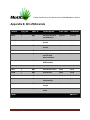
School of Engineering Science
Simon Fraser University
Burnaby, BC V5A 1S6
[email protected]
November 05, 2012
Dr. Andrew Rawicz
School of Engineering Science
Simon Fraser University
Burnaby, British Columbia
V5A 1S6
Re: ENSC 440 Design Specifications for a Motion-Controlled
Controlled Manipulator
Dear Dr. Rawicz,
esign specification document from, which summarizes our
Attached to this letter is the design
detailed technical design considerations for our project.
This design specification detail
details the five technical aspects of our system: RGB/IR depth
sensor, the software,, the hardware ((circuit and micro-controller),
), the user interface, and
the robotic arm manipulator. In each section, the layout and the internal design will be
presented, and each design specification a
applies to the proof-of-concept
concept demonstration
only. Technical engineers and manufacturer will be using this document to further
understand the project.
MotiCon is composed of six enthusiastic and creative engineering students: Kevin
Wong, Kay Sze, Jing Xu, Hsiu
Hsiu-Yang
Yang Tseng, Arnaud Martin and Vincent Wong. If you
have any question, please feel free to contact us by phone at 778
778-889-9950
9950 or by email
at [email protected].
Sincerely yours,
Vincent Wong
President and CEO
MotiCon
Motion-Controlled
Controlled System For
Multi-Purpose
Purpose Robotic Arm
Operations
DESIGN SPECIFICATIONS
Project Team: Vincent Wong
Jing Xu
Kay Sze
Kevin Wong
Hsiu-Yang
Hsiu
Tseng
Arnaud Martin
Contact Person: Vincent Wong
[email protected]
Submitted to: Dr. Andrew Rawicz – ENSC 440
Steve Whitmore – ENSC 305
School of Engineering Science
Simon Fraser University
Design Specifications for Motion-Controlled
Controlled Manipulator System
Executive Summary
At MotiCon, we offer medical and industrial companies a solution for users to control their
robotic arms intuitively. The system basically utilizes a RGB and an infrared depth
d
sensor to
control robotic manipulators simply by movements
movements. The benefit of this product:
•
Offers a simpler method of controlling a robotic arm
•
Utilizes intuitive hand and arm movements to control manipulators and therefore
reduce the learning curve
•
Offers an inexpensive system by reducing the training fee for companies to train users,
due to the system’s intuitive controlling method
•
Increases the degrees of freedom by registering complicated hand movements
As with any project, our design requirements for our motion-controlled
controlled device at MotiCon
consist of the software processing
processing, the hardware controller and the robotic arm.
arm The following
description of our system applies to our proof-of-concept demonstration only.
Our RGB and depth sensing is done solely by the Kinect system, which has high resolution depth
capabilities to detect arm positions in 3D space. Our software processing
ing algorithm uses the
open-source openNI SDK, and performs inverse kinematics to the detected arm positions. The
hardware controller consists of aan Arduino microcontroller and a prototype circuit, designed to
translate the angle outputs of the software side to electrical voltages for the motors when
controlling the robotic arm. The mechanical robotic arm is used to demonstrate that the
integration of the system works.
Furthermore, at MotiCon,, we will undergo comprehensive modular tests to ensure
ensu compliance
with regulations and to guarantee accurate results in the functionally. These design
specifications ensure the success of our prototype system.
Copyright © 2012, MotiCon
1
Design Specifications for Motion-Controlled
Controlled Manipulator System
Table of Contents
Executive Summary................................
.........................................................................................................................
......................... 1
1.
2.
Introduction ................................
...........................................................................................................................
........................... 7
1.1
Scope ................................
................................................................................................................................
................................ 7
1.2
Intended Audience ................................
................................................................................................
........................................... 7
System Specifications................................
................................................................................................
.............................................. 7
2.1
3.
4.
5.
System Overview ................................
................................................................................................
.............................................. 7
RGB/IR Depth Sensor and IR Emitter ................................................................
...................................................... 9
3.1
RGB Sensor ................................
................................................................................................
..................................................... 11
3.2
Infrared Depth Sensor ................................
................................................................................................
.................................... 11
Software and Intercommunication Design ................................................................
........................................... 12
4.1
Software Overview ................................
................................................................................................
......................................... 12
4.2
Inverse Kinematics with Kinect ................................................................
...................................................... 13
4.3
Communication with Arduino ........................................................................................
........................ 18
4.4
OpenGL Framebuffer Display .........................................................................................
......................... 19
Hardware ................................
..............................................................................................................................
.............................. 20
5.1
Microcontroller ................................
................................................................................................
.............................................. 20
5.1.1 General requirements ................................................................................................
.................................. 20
5.1.2 Prototype Design ................................
................................................................................................
......................................... 20
5.2
Circuit ................................
.............................................................................................................................
............................. 21
5.2.1 General requirements
ements................................................................................................
.................................. 21
5.2.2 Prototype Design ................................
................................................................................................
......................................... 22
5.3
6.
7.
Angle to voltage mapping ..............................................................................................
.............................. 24
User Interface Unit................................
................................................................................................
................................................ 25
6.1
Main Menu ................................
................................................................................................
..................................................... 26
6.2
User Tracking Window ................................
................................................................................................
................................... 27
6.3
Visual
al Feedback Window ...............................................................................................
............................... 27
Robotic Arm ................................
..........................................................................................................................
.......................... 27
7.1
OWI-535
535 Robot Arm Edge – with DC motors ................................................................
................................. 28
Copyright © 2012, MotiCon
2
Design Specifications for Motion-Controlled
Controlled Manipulator System
7.1.1 Robot arm specifications .............................................................................................
............................. 28
7.1.2
1.2 DC motor and potentiometer ................................................................
...................................................... 29
7.2
Lynxmotion Servomotor
Servomotor-based AL5D robot arm ...........................................................
........................... 30
7.2.1 Robot arm specifications .............................................................................................
............................. 30
7.2.2 Servomotors and the feedback bus ................................................................
............................................. 31
8.
System Test Plan ................................
................................................................................................
................................................... 33
8.1
Individual Component Testing .......................................................................................
....................... 34
8.2
System Integration Testing ............................................................................................
............................ 35
8.3
Typical Usage Unit Tests................................................................................................
................................. 35
8.3.1
3.1 Detection and basic movements ................................................................
................................................. 35
8.3.2 Picking up small and light objects ................................................................
................................................ 36
8.3.3 Operation on two different arms ................................................................
................................................ 36
9.
Environmental Considerations .............................................................................................
............................. 37
9.1
Prototype Disposal ................................
................................................................................................
......................................... 37
9.2
Product Disposal................................
................................................................................................
............................................. 37
10.
Conclusion ................................
..........................................................................................................................
.......................... 38
11.
References ................................
.........................................................................................................................
......................... 39
Appendix A: Circuit Layout................................
................................................................................................
............................................ 40
Appendix B: Bill of Materials ................................
................................................................................................
......................................... 41
Copyright © 2012, MotiCon
3
Design Specifications for Motion-Controlled
Controlled Manipulator System
List of Figures
Figure 2.1: High-Level
Level Model of MCMS ..........................................................................................
.......................... 8
Figure 2.2: MCMS Prototype Dataflow Diagram ................................................................
............................................ 9
Figure 3.1: Kinect Sensor Components [1] ................................................................
................................................... 10
Figure 3.2: PrimeSensor Data Flowchart [2] ................................................................
................................................. 11
Figure 4.1: High-Level
Level Design of Software ................................................................
.................................................... 13
Figure 4.2: Self-Defined
Defined Robotic Arm Coordinate System ............................................................
............................ 14
Figure 4.3: Default Kinect User Coordinate System, (Y and Z are interchanged)......................... 15
Figure 4.4: Relative Arm Cartesian Coordinates ................................................................
........................................... 16
Figure 4.5: Inverse Kinematics Diagram for Robotic Arm.............................................................
............................. 17
Figure 4.6: Processor and Arduino Serial Communication ...........................................................
........................... 19
Figure 4.7: OpenGL Texture to Framebuffer Mapping [7
[7]............................................................
............................ 19
Figure 5.1: Arduino UNO Pin Configurations [8]................................................................
........................................... 21
Figure 5.2: SN754410 H-Bridge
Bridge Circuit [9] ................................................................
.................................................... 22
Figure 5.3: General circuit component design................................................................
.............................................. 23
Figure 6.1: Full User Interface for Final Product ................................................................
........................................... 25
Figure 6.2: User Interface Menu List ............................................................................................
............................ 26
Figure 7.1: An overview of the DC motor arm configuration [10]................................................
................................
30
Figure 7.2 : Schematic of pulse regulating servo motor ...............................................................
............................... 32
Figure 7.3: Location of servomotors on robot arm AL5D. [11].....................................................
................................
33
Figure 8.1: High-Level
Level Model of MCMS ........................................................................................
........................ 34
List of Tables
Table 3.1: Kinect Specifications [1] ...............................................................................................
............................... 10
Table 5.1: Inputs and Outputs of the SN754410 ................................................................
.......................................... 22
Table 7.1: Specifications of the DC
DC-motor robot arm [10] ...........................................................
........................... 28
Table 7.2: The angular velocity measurements according to DC voltages ...................................
................................ 29
Table 7.3: The specification of the Lynxmotion AL5D (servo
(servo-motor) robot arm [11] .................. 31
Table 7.4: The relationship between the pulse duration and the motor turning direction ......... 32
Table 9.1: Methods of Environmental Friendly Disposal of Prototype ........................................
................................
37
Copyright © 2012, MotiCon
4
Design Specifications for Motion-Controlled
Controlled Manipulator System
Glossary
Glossary: Definition of Terms
Black Box
Opaque system for the user, which cannot distinguish or easily access
the different parts
da Vinci robot
A surgical robotic arm made by Intuitive Surgical company and designed
to facilitate complex surgery using a minimally invasive method
FOV
Field of View is the extent of observable world seen at a given moment
Kinect
A motion-sensing
sensing input device by Microsoft, originally built for Xbox 360
game console, used to detect depth and RGB
MCMS
Motion Controlled Manipulator System - is the product of our company
NUI
Natural User Interface is the common jargon used by designers for
human-machine
machine interface that is natural and barely noticeable to users
OpenNI
Open Natural Interaction is the no
non-profit
profit organization responsible for
developing the open sourced development library that we are using
Perfboard
A thin and pre
pre-drilled
drilled standard board for prototyping electronic circuit.
PWM
Pulse Width Modulation is a way of controlling power to inertial
electrical devices by modulating the pulse waves
RGB
Red Green and Blue is a color model set by adding these 3 colors to
create a broad array of colors
User
An able-bodied
bodied person capable of using both arms voluntarily
UI
User Interface is an in
industrial design field of human-machine
machine interaction
IR
Infrared light, an electromagnetic radiation at 0.74 µm to 300 µm
PC
Personal Computer, a general purpose commercially available computer
H/L Combo
High level (+5V) and low level (0V) voltage combinations sent to the HH
bridge’s input
Copyright © 2012, MotiCon
5
Design Specifications for Motion-Controlled
Controlled Manipulator System
CCD
Charge Coupled Device is a device that moves charge in capacitative bins
to convert photons into electronic charges (bits). CCD sensors are used
for digital photography.
QA
Quality Assurance
Framebuffer
The monitor display buffer responsible for storing pixel information
OpenCV
Open Computer Vision, library capable of providing object detection
OpenGL
Open Graphics Library, cross
cross-language
language library for 2D and 3D rendering
BOM
Bill of Materials is a list of all our sourced parts, model number and cost
DC motor
Direct current motor is an electric motor running on the unidirectional
flow of electric charge, or a constant voltage
Servomotor
A rotary actuator allowing precise control of angular positions with
feedback
H-Bridge
An electronic circuit that enables voltage to be applied across a load in
either direction, which is used in robotics to allow DC motors to run
forwards and backwards
Serial
Communication
A process of sending data sequentially (i.e. one bit at a time) over a
communication channel or computer bus
SDRAM
Synchronous dynamic random access memory is dynamically clocked
memory in sync with the system bus, which allows pipelining to occur
mm, cm
Millimeter is 10-3 of a meter and centimeter is 10-2 of a meter
Copyright © 2012, MotiCon
6
Design Specifications for Motion-Controlled
Controlled Manipulator System
1. Introduction
The MotiCon Motion-Controlled
ontrolled Manipulator System (MCMS) is a black-box system allowing
intuitive motion control of various robotic manipulators by human gesture. The system consists
of hardware, software, and firmware that transmit signal to each other to achieve a desired
physical movement. By sensing the arm movements of the user-operator with the Kinect RGB
and depth sensor, the MCMS can interpret the human motion, and then send the processed
command signals to the microcontroller that regulates the voltage to the motors incorporated
in the mechanical robotics.
1.1 Scope
This document elaborates on the reasoning behind our design choices and lays out the
hardware and software design blocks for MCMS. The design specifications carry out the
concept, mechanism and technical details for our proof of the concept. In addition, a series of
modular test plans for the system
tem are provided at the end o
off the specifications to evaluate the
functions of our prototype.
1.2 Intended Audience
The design specification is written for every team member of MotiCon,, to serve as a design
guide throughout
hroughout the development process
process. The CEO, who is in charge of project management,
will analyze the design specifications and determine how efficient and successful the
t proof-ofconcept prototype is to the end users
users. All engineers will follow the specifications to ensure our
current design development complies with the goal o
of our product. In addition, these design
specifications highlight the challenges and technical feasibility of our project for the engineers,
by allowing all the engineers to have an understanding of the entire project rather than only
their assigned parts. The test plans are intended for application engineers and QA analysts to
use as a template for the evaluation of the product.
2. System Specifications
General requirements applicable to MotiCon MCMS for a complete
ete system are described in the
following sections.
2.1 System Overview
The MotiCon MCMS can be conceptualized as shown in Figure 1 below.
Copyright © 2012, MotiCon
7
Design Specifications for Motion-Controlled
Controlled Manipulator System
Figure 2.1: High-Level Model of MCMS
The MCMS will be implemented in a black box which sends and collects infrared
red rays to detect
any movement of the environment
environment.. This product simply allows users to plug in their specific
robotic tools to the black box to control it via motion control. The black box remains specific for
each application due to the differences in the re
required output. Data processing and calculations
will be done in the black box and tthe joint’s target signals will be sent from the black box to the
executor. These signals are computed with an inverse kinematics algorithm determining the
target position of each joint of the robotic arm to reach the target point designated by the
hand. As a result, the robotic arm manipulator moves according to the user hand position.
A further concept model is shown in Figure 22.2 which layout all the major components of our
ou
prototype system. Any more advanced application might require some modifications and
developments in the system.
Copyright © 2012, MotiCon
8
Design Specifications for Motion-Controlled
Controlled Manipulator System
Figure 22.2: MCMS Prototype Dataflow Diagram
From the figure, when
hen the user moves in front of the Kinect sensor, the sensor detects the ‘arm
joint angles’. Within
ithin the laptop, the software performs the image processing that calculates the
desired target angles and directions using inverse kinematics method. The laptop then sends
these resulting target signals to the Arduino board through the serial communication port.
port The
Arduino program sends the converted signals to an H-bridge circuit while receiving angle
feedback from the potentiometers on the robotic arm. With the
these
se two kinds of signals, the
Arduino program is able to determine the duration of each trajectory, and knows the current
location of the effector and the remaining distance required to arrive at the target position.
Moreover, the circuit provides high cur
current to power motors and acts as a switch. The circuit
receives high and low level signals from the Arduino, and outputs high current voltages to
control the motors. The circuit sends H/L voltage combination as shown in Figure
igure 2, where ‘H’
is 5V and ‘L’ is 0V. For example, an H/L combo spins the motor clockwise and an L/H combo
spins the motor counterclockwise
counterclockwise. Furthermore, an external power supply provides
provid 5V and up
to 3A to operate the motors.
3. RGB/IR Depth Sensor and IR Emitter
The color sensor detects color with standard CCD sensors, whereas the IR depth sensor detects
infrared reflections off of an object
object.. By using the infrared emitter which emits invisible infrared
light and measuring light intensity after reflecting off the object, the depth of the object from
the sensor can be measured. In the product, tthe
he depth camera and emitter must be small and
modular fit and effective enough to get high
high-resolution depth information.
Copyright © 2012, MotiCon
9
Design Specifications for Motion-Controlled
Controlled Manipulator System
However for the design specifications
specifications, we will analyze the Kinect system as shown in Figure 3,
3
which we are using for the prototype. The rationale behind why we chose to use Kinect is:
•
•
•
It provides high-resolution
resolution depth and color sensing in 3D space
With the limitations of time for this project, using the Kinect system is feasible and quick
There are many online resource for software development using Kinect
Figure 3.1: Kinect Sensor Components [1]
The properties and values of the Kinect are specified in the table below.
Table 3.1: Kinect Specifications [1]
Property
Value
Angular Field-of-View
57° horizontal, 43° vertical.
Frame rate
Approximately 30Hz
Nominal spatial range
640 x 480 (VGA)
Nominal Spatial Resolution (at 2m distance)
3mm
Nominal depth range
0.8m – 3.5m
Nominal depth resolution (at 2m distance)
1 cm
Device connection to PC
USB (+external power)
Copyright © 2012, MotiCon
10
Design Specifications for Motion-Controlled
Controlled Manipulator System
The Kinect consists of 4 microphones, an IR transmitter, one infrared camera, one standard
visual-spectrum
spectrum camera for visual recognition, cooling fan, 64MB of Hynix DDR2 SDRAM, a small
DC motor and a three-axis accelerometer to pan the motor [1].
3.1 RGB Sensor
The RGB sensor is a standard color video camera that detects red, green and blue color
components. It stores the three channel data in a 1280x960 resolution, so that capturing the
color image is possible. The color image is sent to the PrimeSense PS1080-A2 SoC for processing
[1].
3.2 Infrared Depth Sensor
The depth sensor utilizes an infrared projector and monochrome CCD sensor fitted with an IRIR
pass filter. Inside the Kinect, the
he PrimeSense
PrimeSense’s “PS1080-A2” integrated circuit calculates the
depth information for each frame from the data collect
collected at the visible light camera and sends
the information to the host device via USB 2.0 interface. This SoC system is called PrimeSensor
as illustrated in the figure below on how the depth perception on the Kinect sensors works [1].
Figure 3.2: PrimeSensor Data Flowchart [2]
From the Figure
gure 4, the PrimeSenso
PrimeSensor of Kinect is built around the PrimeSense’s PS1080 SystemSystem
on-a-chip (SoC), which controls the IR light source to project the sce
scene
ne with an IR Light Coding
image. The “IR Light Coding” is works by coding the scene volume with near
near-IR
IR light. The IR
Copyright © 2012, MotiCon
11
Design Specifications for Motion-Controlled
Controlled Manipulator System
projector is a Class 1 safe light source and is compliant with the IEC 60825
60825-1
1 standard so it’s
safe for environmental use.. The standard CMOS image sensor receives IR light and transfers the
IR Light Coding image to PS1080. The PS1080 processes the IR image and produces an accurate
per-frame
frame depth image of the screen [2]. In order to perform accurate sensory information, the
PrimeSensor’s SoC performs a process called Registration,, which results in images being pixelpixel
aligned and that every pixel in color image is aligned to a pixel in the depth image.
4. Software and Intercommunication Design
The primary functionality of the software is to compute and deliver accurate values
representing the positioning of the user, which includes the segment angles corresponding to
each of the user’s joints. There are many methods in robotics to navigate a robotic
botic arm or any
other type of effector, such as forward kinematics and inverse kinematics. However in our
software, we focus purely only on the inverse kinematics algorithm due to it being much more
intuitive for the user to operate with. This section will describe the three high-level
level components
that comprises of the functionality required for communication with the Kinect, the Arduino
Serial port, and the monitor display
display,, and each of their roles contributing to the inverse
kinematics algorithm.
4.1 Software Overview
The high-level
level design of our software consists of three main libraries which construct the
foundation of the whole program:
• Open Graphics Library (OpenGL)
• Open Natural Interaction (OpenNI)
• Serial Communication Library
Using these three libraries,, we are able to produce a stable communication between the Kinect,
the computer, the Arduino,
rduino, and the
therefore the robotic arm. To understand the high level
components of our software, Figure 4.1 illustrates each of th
them and how they interact and
communicatee between other software and hardware components.
Copyright © 2012, MotiCon
12
Design Specifications for Motion-Controlled
Controlled Manipulator System
Figure 4.1: High-Level Design of Software
In Figure 4.1, the three major components are directly related to the three libraries used,
OpenGL, OpenNI,, and Serial COM. The communication between OpenGL and OpenNI are
bidirectional, meaning information is constantly being sent in both directions in order to allow
proper signal processing of the depth acquisition data from the Kinect sensor. The interaction
interact
between OpenGL and the Serial Communication is only unidirectional, as the microcontroller
only requires the endpoint values of the end effector position, and it does not require sending
information back to OpenGL,, which simplify the interchangeability of the robotic arm.
arm Finally,
OpenGL is able to access the Graphics Processing Unit's framebuffer, in which images are stored
pixel by pixel, then send to display once every cycle, approximately 30 Frames Per Second. The
following sections will describe eeach of these components into greater detail.
4.2 Inverse Kinematics with Kinect
To communicate with Kinect, the correct drivers must be used to achieve the desired control
over the integrated hardware. In this program, we used the Kinect drivers developed by the
organization called "Open Natural Interaction", or "OpenNI" [3].. The OpenNI toolkit for Kinect
allows the direct interaction with the Kinect's Infrared Sensor, RGB detector, and Microphone
for voice control.. Using OpenNI, the depth information is cap
captured
tured for the Human, and this
information is converted into three
three-dimensional
dimensional coordinates, which we will use for the
following Inverse Kinematics algorithm. The rationale
ale behind why we chose to use OpenNI
O
instead of the Microsoft
icrosoft Kinect SDK is because O
OpenNI provides flexibility to program, and is
compatible with various operating systems.
Copyright © 2012, MotiCon
13
Design Specifications for Motion-Controlled
Controlled Manipulator System
The rationale behind why we chose to use Inverse Kinematics as a motion
motion-planning
planning algorithm is
because it provides an intuitive navigation of the end effector with respectt to the user’s hand,
without having concerns about for joint angles [4].
The current design for the Inverse Kinematics algorithm operates with three free angles, the
base rotational angle, the shoulder axial angle, and the elbow axial angle. These angles
angl are
defined in correspondence with the coordinate system we assigned for the robotic arm.
Figure 4.2 demonstrates the x-,, yy-, and z- axes assigned to the robotic arm’s coordinate system.
Figure 4.2: Self
Self-Defined Robotic Arm Coordinate System
In Figure 4.2,, we can see that the yz
yz-plane corresponds to the sagittal plane, xz--plane
corresponds to the frontal plane, and the xy
xy-plane
plane corresponds to the transverse plane [4]. In
order to map these coordinates directly to the positions of the user’s arm with respect to the
Kinect’s detector, we need to determine the default coordinate system integrated within
Kinect, which are shown in Figure 4.
4.3.
Copyright © 2012, MotiCon
14
Design Specifications for Motion-Controlled
Controlled Manipulator System
Figure 4.3: Default Kinect User Coordinate System, (Y and Z are interchanged)
The coordinate of the arm will be translated using the shoulder coordinates as the reference
point (i.e. the origin). This means that the coordinate of the should
shoulder will become [0,0,0], and
the relative hand coordinates will be derived based on this reference point. In order to obtain
the relative coordinates, we use the following set of equations:
. . . (4.1)
. . . (4.2)
. . . (4.3)
To demonstrate how the equations above determine the relative coordinates,, here is a figure
that illustrates the mechanism where the shoulder has been placed at the origin.
origin
Copyright © 2012, MotiCon
15
Design Specifications for Motion-Controlled
Controlled Manipulator System
Figure 44.4: Relative Arm Cartesian Coordinates
The relative coordinates of the hand will then be normalized by the total llength
ength of the arm, as
demonstrated in the following example of equations:
. . /
(4.4)
. . /
(4.5)
. . /
(4.6)
Using the normalized coordinates, which range from 0 to 1, multiplied values by the length of
the robotic arm, we can obtain the corresponding coordinates in the robotic arm’s
arm operational
area.
. . ∗ (4.7)
. . ∗ (4.8)
. . ∗ (4.9)
In order to translate robotic hand coordinates into the corresponding robotic arm angles via
inverse kinematics, it is first necessary to determine the priority of angles for calculation. The
current inverse kinematics implementation iiss able to control three motors controlling the base
rotational motion, the primary section’s translational motion, and the secondary section’s
translational motion. The mathematical calculations required by these three angles are derived
using the robotic hand Cartesian coordinates derived above, presented in the following set of
equations. Figure 4.5 illustrates the concept for Inverse Kinematics in calculating the angles
required corresponding to the robotic arm.
Copyright © 2012, MotiCon
16
Design Specifications for Motion-Controlled
Controlled Manipulator System
Figure 4.5:: Inverse Kinematics Diagram for Robotic Arm
From Figure 4.5,, the first angle to be calculated is the angle , which determines the base
rotation angle, as explained in equation 4.10.
34546789:;<.=
Ɵθ 234546789:;<.> ?
(4.10)
The length of the end effector vector must be predetermined before further calculations of the
first and second joint angles.
Vectorlength @. 1 A . 1 A .
1
(4.11)
With the length of the end effector vector, we can derive an equation based on the cosine law
in order to calculate the angle β. , as demonstrated in equation 4.12.
β. arccos
arccos 2
BCCD3E3FGD;H IJ4KD3E3FGD;H LMD8643JD;N6OH
1∗BCCD3E3FGD;∗MD8643JD;N6O
?
(4.12)
The angle β. is merely the relative angle between the base robotic arm segment and the end
effector vector. To determine the absolute angle, the an
angle β1 is calculated using equation
eq
4.13.
β1 arctan
arctan P
34546789:;<.Q
@34546789:;<.> H L34546789:;<.= H
R
(4.13)
Therefore we can derive the absolute angle of the first translational motor using β. and β1 .
1 β. A β1
Copyright © 2012, MotiCon
(4.14)
17
Design Specifications for Motion-Controlled
Controlled Manipulator System
To calculate the angle of the second motor, we use another derivation of the cosine law
equation in order to calculate α..
2 α arccos 2
BCCD3E3FGD;H LJ4KD3E3FGD;H IMD8643JD;N6O
OH
1∗BCCD3E3FGD;∗J4KD3E3FGD;
?
(4.15)
The robotic arm segment lengths must be calculated for each different robotic device, which
can vary the angles significantly for different sizes and models of robotic arms. The robotic arm
used in our test system will consist of many more constrai
constraints than a fully developed robot, such
as the da Vinci robot,, due to our basic and rudimentary prototype testing. These constraints
include characteristics such as degrees of freedom and reliability. In the actual design, the
robot, or manipulator, will have no physical constraints, and each end effector will exactly
exa
imitate the movements generated by the system user.
The end effector of our current robotic arm has the gripping functionality. To enable this
functionality,, we plan to use hand movements to control the gripping. However, OpenNI
provides a simple hand
d detection which only indicates the position of the hand without any
finger detection. Instead, there is a library called Open Computer Vision (OpenCV), which is
capable of object detection, including the user’s hands and wrists. This library can be used also
to detect gestures formed with the hand; therefore we can correlate a fist clenching and fist
opening with the robotic arm’s gripping motion.
For further developments of applications, different methods of hand movement recognition
might be introduced. But the question is not essential for a prototype building.
4.3 Communication with Arduino
In order to communicate with Arduino Uno, the Arduino must be uploaded with a sketch [6].
The sketch is a simple code written and compiled using C++ syntax, however the Arduino
compiler converts the C++ code into machine code and uploads it into the Arduino
microcontroller. Therefore the Arduino will be an independent operating system requiring its
own compilation code.
In order to communicate with the Arduino micro
microcontroller,
controller, a USB serial connection will be
used, where bytes of information will be sent from the main processor to the Arduino
Microcontroller via this communication port [6].. The sketch uploaded to the Arduino
microcontroller will instruct the microcon
microcontroller
troller to inspect the serial communication port for
sufficient information, and to read out the bytes upon receiving sets of three bytes.
Copyright © 2012, MotiCon
18
Design Specifications for Motion-Controlled
Controlled Manipulator System
Figure 4.6:: Processor and Arduino Serial Communication
The Arduino will then be instructed to convert these bytes into the equivalent voltages, which
have been pre-calibrated
calibrated by manual testing of the robotic system, with each voltage
corresponding to an angle, as explained in section 5.3.
4.4 OpenGL Framebuffer Display
Using OpenGL, we are able to access the monitor's framebuffer [7].. In this framebuffer, each of
the calculated pixels is mapped correspondingly to the buf
buffer coordinates,, where the buffer is
then sent to the monitor display
display. Therefore, by mapping each of the acquired depth signals
into the depth buffer and converting the real
real-world
world coordinates into pixel coordinates, the
program is able to draw out exactly what the Kinect
inect sensor detects in the infrared region.
Figure 4.7:: OpenGL Texture to Framebuffer Mapping [7]
This method basically writes the information into the display window’s framebuffer pixel by
pixel, via the pixel buffer object. Our design for OpenGL will be to use glDraw for drawing each
pixel into the texture, which will then be unpacked into the pixel buffer object. The whole pixel
buffer object will be mapped onto the display window’s frame buffer.
Copyright © 2012, MotiCon
19
Design Specifications for Motion-Controlled
Controlled Manipulator System
5. Hardware
The hardware packaging of our system consists of a microcontroller and an H-bridge
bridge circuit
design. The microcontroller output
utputs controlling voltage signals to the DC or servo motors and
receives feedback signal from the robotic arm joints (using potentiometers). The H-bridge
H
circuit acts as a selective switch to turn motors in clockwise/counter
clockwise/counter-clockwise
clockwise rotation
according to desired angle. Our ha
hardware is powered by an external high current DC power
supply,, and the 5V (maximum 450 mA can be drawn) output pin. In order to map the voltage
to angle on the robot arm, we will explain the method and our results of the angle ranges we
have for the DC-motor arm.
5.1 Microcontroller
5.1.1 General requirements
The microcontroller is connected to the signal processing hardware (e.g. a computer)
computer through a
serial communication port (USB), and receives the joint positions to be reached by the robotic
arm. The goal of this part is to make sure that every joint reach
reaches its final position. The
complexity of the algorithm enabling this task can change from one application to another.
The microcontroller system design consists of retrieving the angle position of each joint
jo in
digital, from servos, or in analog, from simpler sensors like potentiometers, and compares it to
the angles received from the image processing step. Depending on the comparison, the
microcontroller sends the signal to move or not each joint in one o
orr another direction. The
speed of the movement can also be controlled in more complicated and precise applications.
By simplifying the role of the microcontroller, we intend to provide a product that can easily
adapt on each manipulator application we inte
integrate with.
5.1.2 Prototype Design
For the prototypes of our product, we used the ATmega328-based Arduino UNO
microcontroller [5],, which is a relatively cheap and straightforward microcontroller to use.
use It
enables us to perform simple control operations on the joints, receiving their angular position
through the digital or analog inputs (depending on the robotic arm).
Copyright © 2012, MotiCon
20
Design Specifications for Motion-Controlled
Controlled Manipulator System
Figure 55.1: Arduino UNO Pin Configurations [8]
The desired angles for the arm are received from the computer through the serial
communication port.. For the OWI prototype, the Arduino receives the target angle positions of
the three main joints (ref. corresponding section) from three analog inputs (A0
(A0--A2) using a 10bit encoder. This encoder
oder thus provides the possible integer values ranging from 0 and 1023,
which correspond to a voltage from the potentiometers of 0 to 5V.These potentiometers are
powered directly by the Arduino
Arduino’s 5V output, which generates an equivalent current of 1.5
mA.This
This current is far from exceeding the Arduino’s current protection limit of 40 mA.
The motors on the joints of the robotic arm are controlled by the signals coming from the
digital outputs of the Arduino (D2
(D2-D4-D7-D8-D10-D11).
D11). Two outputs are necessary to control
one joint in the two directions of rotation. An enabling output (D0) is also used to turn on/off
the entire circuit.
5.2 Circuit
5.2.1 General requirements
Unfortunately, the microcontroller cannot provide the power for the joints the move, neither
for
or the prototype or the more complication applications. We then need a circuit that could
transform the signals from the microcontroller into actual power, usable b
byy the joints of the
robotic arm. In addition, it can act as a switch to turn on motors we ne
need,
ed, and to rotate the
motors clockwise/counter-clockwise.
clockwise.
Depending on the application (Prototype – Shovel – Surgical Robot), the amount of power going
through the circuit can attain up to hundreds of Watts. By using an external circuit for
converting the microcontroller outputs into actuating signal for controlling an external power
supplies’ current throughput, we can protect the system components from serious damage due
to excessive consumption of current.
Copyright © 2012, MotiCon
21
Design Specifications for Motion-Controlled
Controlled Manipulator System
5.2.2 Prototype Design
For the prototype, H-Bridges
Bridges are used to control the motors. They require very low power
consumption at their input and provide as much as 1A for each joint when connected to an
external power source. The H-bridges
bridges that we used ar
are
e called SN754410 Quad Half high current
H-Bridge, which uses (transistor--transistor logic) TTL 5V logic levels for bidirectional drive.
drive It has
1A and 4.5V to 36V output capability per driver. The following is the connection of the motor
driver:
Figure 5.2: SN754410 H-Bridge Circuit [9]
With the proper data inputs, each pair of drivers of the H
H-bridge can form a full-H
full (or bridge)
reversible drive suitable for motor applications as seen in the table below:
Table 5..1: Inputs and Outputs of the SN754410
Inputs
Output
Motor1
Forward
Motor1
Reverse
EN
Motor 1 output (Both Green lines)
lines
H
L
H
5V (Forward)
L
H
H
-5V (Backward)
X
X
L
Z (0V)
H/L
H/L
H
Z (0V)
Copyright © 2012, MotiCon
22
Design Specifications for Motion-Controlled
Controlled Manipulator System
In this table, ‘H’ is high level voltage (5V), ‘L’ is low level voltage (0), X is irrelevant, and Z is
equal to impedance (off). We can see that the combination of high and low voltages would
alter the output voltages of the H
H-bridge
bridge circuit by flipping the polarity and reversing
revers the DC
motors controlling the robotic arm.
The rationale behind using the H
H-bridge
bridge circuit is to provide high current output to power the
motors, to control the direction of motor rotation, and to use the enable pin to control the
speed of the motor by using PWM (Pulse Width Modulation). In addition, the H-bridge
H
is much
cheaper than buying a premade Arduino Motor Shield circuit
circuit,, which has a combination of other
unnecessary circuit parts.
Below is a general circuit diagram of our hardware design.
Figure 55.3: General circuit component design
Refer to the appendix for the con
connections
nections of the actual hardware circuit. In essence, our design
will generate robot arm feedback information from the potentiometers, which varies the
internal resistance when the wiper (i.e. the rotational knob) is adjusted on the potentiometer.
For the potentiometers we used the 10
10kΩ trimpots and installed them onto the arm, and we
set the DC motors (1, 2, and 3) fo
for the shoulder, the elbow and the hip respectively.
respectively
However, this design will differ with the servo motor arm because servo motors have and
integrated feedback input and output signal for the motor’s angle, which can be directly fed
back into analog inputs
uts (A0, A1 and A2) of the Arduino UNO for control feedback. Only the first
prototype is entirely explained in these specifications.
Copyright © 2012, MotiCon
23
Design Specifications for Motion-Controlled
Controlled Manipulator System
5.3
Angle to voltage mapping
The linear relationship of the voltage to angle range of the arm is shown in the equations
below.
A (5.1)
Where y is the output, x is the input, m is the slope, and b is the yy-intercept
intercept when x = 0. Within
our Arduino sketch, the following linear relationships were mapped by the integer type values
from the Serial Port analog read of the voltage (after passing the standard Arduino 5V across
the varying potentiometers). We then mapped the integer values according to our reference of
2 measured angles. By mapping two voltage values to angle values, we determined the slope
with the formula:
M4J6:NDHlbmlnYX IM4J6:NDo_^mlnYX
mlnYX
∆E;NJD
(5.2)
And the y-intercept
intercept at elbow angle = 0 gives
.
(5.3)
As a result, for the linear angle to voltage relationships, the elbow joint gives:
VDJ54K<DW73D Where integer of Velbow
MXYZ[\]^
]^qr° IMXYZ[\]^r°
at 90°=
st°
uDJ54K<DW73D A VDJ54K:6t°
580 and integer of Velbow
at 0° =
(5.4)
97.
For the shoulder joint:
VWO4BJ<D3<DW73D M_`[aYbXc]^de
de° IM_`[aYbXc]^qr°
fg°
uWO4BJ<D3<DW73D 45° A VWO4BJ<D3
4BJ<D3:6fg°
(5.5)
Where integer of VWO4BJ<D3:6fg° = 150 and VWO4BJ<D3:6st° 415.
For the hip joint:
VO7C<DW73D M`
`xy]^de° IM`xy]^r°
fg°
uO7C<DW73D A VO7C:6t°
Where VO7C:6fg° 670 and VO7C
7C:6t° = 485.
Copyright © 2012, MotiCon
24
(5.6)
Design Specifications for Motion-Controlled
Controlled Manipulator System
6. User Interface Unit
Intuitive operability of the Natural User Interface (NUI) is a key to the application design and
usability. The interface will be purely controlled by motion and gestures of the user and the
system will provide visual feedback of the manipulator orientation. The user interface that will
be implemented in the final design
ign of the software will include three different sub-windows.
sub
The functionality corresponding to each sub
sub-window will be the following:
•
•
•
User Menu
User Tracking
Visual Feedback
Figure 6.1 displays all three sub-windows
windows in the User Interface design for the ffinal
inal product.
However due to a limited amount of time, we may not be able to accomplish exactly as shown
in this design before completion of the prototype. We will aim to achieve the Menu
functionality and the user tracking window functionality before the demonstration of our
prototype.
Figure 66.1: Full User Interface for Final Product
Copyright © 2012, MotiCon
25
Design Specifications for Motion-Controlled
Controlled Manipulator System
6.1 Main Menu
The Main Menu will display four options, Start, Load Calibration, Voice Control, and Exit. These
options are shown
n in Figure 6.2. The Menu will be navigated using the left hand. The User
Tracking window, as shown above in Figure 6.1, will consist of a green box which follows the
user, and whenever the user’ss left hand interacts with this green box, a cursor will appear
ap
in the
menu list. Therefore the user will be able to control the cursor with only the left hand.
Figure 6.2: User Interface Menu List
The Start button is the option to begin tracking for users within the Kinect’ss field of view. The
Load Calibration will allow the user to load a pre
pre-initialized
initialized calibration of the robotic arm
position in order to navigate the arm without tracking the user. The Voice Control option will
enable voice
oice control, so the user will be provided with a list of oral commands in which the
Kinect will be able to receive and perform the resulting instruction. Lastly
Lastly, the Exit button
closes the whole program.
The Start button will bring the user to the Start Menu, containing four subsequent options:
Start Tracking, Pause Tracking, Recalibrate User, Previous Menu. These opt
options
ions are displayed in
Figure 6.2,, having a similar format as the main menu.
Start Tracking will enable the Kinect tracking option, which is to detect the User’s motion in the
right arm, and map this movement to the robotic arm. Pause tracking will freeze the robotic
arm’s current position and stop the user tracking function called after Start Tracking.
Recalibrate User will be used in the eevent where Kinect can no longer detect accurately where
the user is within its FOV (field
field of view
view),, and therefore a recalibration is required. Previous
menu will lead the user back to the Main Menu.
Copyright © 2012, MotiCon
26
Design Specifications for Motion-Controlled
Controlled Manipulator System
Further functionality will be added upon more in
in-depth testing and user validation of our
program.
6.2 User Tracking Window
The User Tracking Window will display the depth information captured by the Kinect’s Infrared
depth sensor camera. Each of these depth pixels will be mapped into the OpenGL texture, and
then
hen displayed onto the monitor. The User Tracking window will only detect the joint locations
for the left and right arms, and their corresponding segments. The limitation with the OpenNI
drivers is that it does not contain finger detection, and therefore
e OpenNI itself can not
differentiate the difference between an open hand and a clench fist. In order to resolve this
issue, we are investigating OpenCV, which provides libraries for detection of natural
components such as the hands and fingers [5]. This functionality will be used for controlling the
robotic arm’s gripper functionality.
The User Tracking window will also draw out a green box, above the left hand’s operational
space. This green box will indicate to the user where the left hand can move in order to
navigate the main menu. Using OpenCV’s finger detection, we can use this ability to track the
user’s left hand’s finger motion, which will differentiate when the user is or is not selecting a
button [6].
6.3 Visual Feedback Window
The Visual Feedback
ck window will simply be a surveillance camera monitoring the whereabouts
of the end effector.. This will provide visual feedback to the operation of the robot, allowing the
remote motion control of our system. In the final product, the system user can be in a
completely different room of the robotic device (e.g. the DaVinci Robot). With the visual
feedback window, they can have accurate real
real-time information of the motion--trajectories and
obstacles needed for proper navigation of surgical procedures.
7. Robotic Arm
For the design of the prototype,, robot
robotics arms are responsible to execute the motions
determined by the black box. According to the usage of the manipulator,, different types of
motors should be chosen for the execution part. Due to this issue, a DC motor robot arm and a
servomotor robot arm were purchased for testing the portability of the black box system.
Copyright © 2012, MotiCon
27
Design Specifications for Motion-Controlled
Controlled Manipulator System
7.1 OWI-535
535 Robot Arm Edge – with DC motors
7.1.1 Robot arm specifications
From the specification table below, the maximum lifting weight provi
provides us with a limit on the
objects for the DC-motor robot arm to pick up during the testing [10].. Also the horizontal and
vertical maximum reaching length and the dimensions are important parameters when we
implement the inverse kinematic algorithm in the software program. In addition, the power
source recommendation is not being used in this project; a direct DC power supply customized
with a power controlling circuit w
will be used in the final prototype.
Furthermore, there are five degrees of freedom in tthis
his robot arm, which are elbow pitch
rotation, the base yaw and pitch rotation
rotation, the wrist pitch rotation, and the gripper
gripp clench. From
the inverse kinematic calculation, the microcontroller will be sending the resulting angles
(ensuring it is within rotation range of the robot arm) to the manipulator.. Again, motions of the
robot arm are determined from the magnitude and the polarity of the analog voltage signals
that is sent.
Table 7.1: Specifications of the DC-motor robot arm [10]
Maximum lift
100 grams
Horizontal reach
12.6”
Vertical reach
15”
Dimensions
9”(L) x 6.3” (W) x 15”(H)
Degree of Freedom
5
Weight
658 grams
Wrist motion
120 degrees
Extensive elbow range
300 degrees
Base motion
180 degrees
Base rotation
270 degrees
Power Source
4 x “D” Batteries
Copyright © 2012, MotiCon
28
Design Specifications for Motion-Controlled
Controlled Manipulator System
7.1.2 DC motor and potentiometer
There are five identical DC motors implemented in this arm. The way to operate the DC motors
is as easy as providing a constant DC voltage. The speed of the DC motors is controlled by the
magnitude of the voltage applied, and the motor turning direction is controlled by the polarity
of the voltage applied.. For example, the following table shows our recording of how the voltage
values relate to the motor operating velocities:
Table 7.2: The angular velocity measurements according to DC voltages
DC Voltage
applied (V)
5
4
3
2
1
0
-1
-2
-3
-4
-5
Angular velocity
(rad/s)
-0.46 ± 5%
-0.38 ± 5%
-0.26 ± 5%
-0.21 ± 5%
-0.11 ± 5%
0
0.12 ± 5%
0.18 ± 5%
0.24 ± 5%
0.37 ± 5%
0.47 ± 5%
** Positive angular velocity rotates in clock
clock-wise direction and vice versa
Copyright © 2012, MotiCon
29
Design Specifications for Motion-Controlled
Controlled Manipulator System
Figure 7.1: An overview of the DC motor arm configuration [10]
As a result, DC motors are very easy to operate and to communicate with the Arduino board or
other microcontrollers,, but still requires H
H-bridges to power.. Yet, since there is no feedback
system implemented with DC motors, feedback sensors should be installed onto
to the robot arm
to indicate how much the robot arm has moved in a given time.. In this case, potentiometers are
used and placed at the joint positions and to the base rotation position. Voltage will be applied
to these potentiometers,
iometers, and voltage signals will be sent to the Arduino board as signals to stop
sending actuating signals to the arm. The potentiometer acts as a voltage divider with varying
resistance as the wiper is adjusted to collect the position data by knowing how much the
resistance change.
7.2 Lynxmotion Servomotor
Servomotor-based AL5D robot arm
7.2.1 Robot arm specifications
Since a feedback system is already built in each servomotor, there is no need of installed
potentiometer on the robot [11]
[11].. This would give a better layout and portability to the system
because less wires and soldering are required to build the mechanical arm. The drawback of
Copyright © 2012, MotiCon
30
Design Specifications for Motion-Controlled
Controlled Manipulator System
servomotors is that the method to operate them is way more complicated than that of DC
motors. This is the reason MotiCon decided to start with an easy arm like the previous one.
Here are the specifications of the robot arm AL5D:
Table 7.3: The specification of the Lynxmotion AL5D (servo
(servo-motor) robot arm [11]
Maximum lift
Weight
Motion range of each motor
Vertical reach
Shoulder to elbow distance
Elbow to wrist distance
Degree of freedom
Gripper opening
Operating voltage
365.54 g
878.84 g
180 degrees
19.00”
5.75”
7.375”
5
1.25”
4-6 DC Votlage
To customize the black box for another device or tool, some of the parameters in the software
algorithm have to be modified.. For example, the vertical reach, the maximum lifting weight and
the limits of the motion range are motional significant factors when calculating how much the
robot arm can move. Also, the lengths of each segment should be modified in the inverse
kinematic calculations within the code
code.. Since the degree of freedom and the locations of the
motors are the same as the robot arm OWI 535, we can keep the same control flow of this arm.
Those modifications are quite easy compared to the complexity of the entire system, which
shows a good tool interchangeability for our black box.
7.2.2 Servomotors and the feedback bus
There are five similar servomotors controlling this arm. To operate servomotors, square wave
pulse signals are necessary [11].. The servomotor
servomotors read the incoming signals every 20ms. Within
the 20ms, the duration of the pulse controls the motion direction and the magnitude
magnitu of the
pulse controls the speed. The critical duration for determining the motor motion is 1.5ms, that
means a pulse with a duration longer that 1.5ms would drive the motor to a clockwise motion
and shorter than 1.5ms results in a counter clockwise direction.. The servomotor will not move if
the pulse duration is exactly 1.5ms. Below is a figure that illustrates the input and outputs of
the servomotor.
Copyright © 2012, MotiCon
31
Design Specifications for Motion-Controlled
Controlled Manipulator System
Figure 7.2 : Schematic of pulse regulating servo motor
Table 7.4: The relationship between the pulse duration and the motor turning direction
Pulse duration
1.0 ms
1.5 ms
1.8 ms
Motor motion
Counter clockwise
Stop
Clockwise
In each servomotor, there are three connection wires from the motor, black, red and yellow.
The black line should connect to ground and the red line to the 4V-6V
6V DC power supply, and the
yellow line is a bi-directional
directional bus which sends signals to motor and receive the feedback signals
from the motor. Furthermore, the Arduino open source data base contains a specific library for
operating servomotors. This simplifies the process to make the servomotors working and
increases the portability of switching from D
DC motor robotic arm to a servomotor robotic arm.
The figure below shows the servomotor based robotic arm.
Copyright © 2012, MotiCon
32
Design Specifications for Motion-Controlled
Controlled Manipulator System
Figure 7.3:: Location of servomotors on robot arm AL5D. [11]
8. System Test Plan
To ensure a fully functioning product, MotiCon intends to implement a rigorous test plan to
test individual modules, the final prototype and the final product. Each component of the
system needs to be tested and approved as an individual entity before testing the complete
system.
Our test plan will go as follows:
Copyright © 2012, MotiCon
33
Design Specifications for Motion-Controlled
Controlled Manipulator System
Figure 8.1: High-Level Model of MCMS
8.1 Individual Component Testing
Individual module testing will be performed on each aspect of the project as th
they
ey are
completed. These tests include, but are not limited to the following.
RGB Depth Sensor and Infrared Emitter
•
•
•
Ability to capture depth and RGB signals of a moving subject in real
real-time
time
Ability to capture a subject with a defined resolution depth
Ability to capture a subject within a defined range
Software
•
•
•
Ability to calculate joint angle values
Ability to use inverse kinematics mathematic to define angle positions
Ability to output correct signals to be converted to analog voltage on motors
Hardware
•
•
Ability to convert the digital output to high
high-current
current analog voltage for DC motors
Ability to detect robotic arm position by servo control, and to compensate for
uncertainties in motion
Robotic Arm
Copyright © 2012, MotiCon
34
Design Specifications for Motion-Controlled
Controlled Manipulator System
•
•
•
Ability to move accordingly to the human hand
Ability
lity to perform movement from start to end point using inverse kinematics
Ability to pinching motion
User Interface
•
•
Ability to select parameters prior to controlling robotic arm
Ability to provide users with visual feedback for robotic arm position
8.2 System
m Integration Testing
After integration, it is important to ensure that each component is fully functioning to relay any
sensor-detected
detected arm movements to robotic arm movements.
This part will necessitate sub-integration
integration unit testing with the communication between
Software and Hardware parts or Hardware to Robotic parts. Those tests will demonstrate the
compatibility of the different components.
Finally, the entire system will be tested for different scenarios and situations. The diversity of
those tasks and the quality of the prototype will indicate the precision and quality of our final
product.
The testing should also account for human user interface like the ease and comfortableness of
the control and the clarity of the human interface.
8.3 Typical Usage Unit Tests
8.3.1 Detection and basic movements
Goals:
This unit test of the entire system attempts to detect the
e human and the movements of the
robotic right arm and the application of corresponding movements to the robotic arm.
Conditions: The user will turn on the system and step forward to be detected. He will then
execute some basic right arm movements in a small area in front of him.
Expected Observations:
The observation of a similar movement for the robotic arm will determine if the entire system
works
orks correctly and if the realization of a complete black box is achieved.
Copyright © 2012, MotiCon
35
Design Specifications for Motion-Controlled
Controlled Manipulator System
8.3.2 Picking up small and light objects
Goals:
In order to determine if the product will be able to perform several tasks, we can show that the
built prototype can itself be used tto
o perform a single task like picking up an object such as a
table tennis ball or a screw driver. This will demonstrate that the idea of capturing human arm
movement to perform tasks on a robotic arm of different size could improve future
development of robotics. Ideally, MotiCon would like to compare the operation of a same take
with and without our system to demonstrate how intuitive this new system will be.
Conditions:
Place the selected object within the range of the robotic arm. Set up the user to be detected,
and the user will attempt to pick up the object successfully.
Expected Observations:
Thee user will be able to pick up the selected object with the robot arm using just his arm
movements.
8.3.3 Operation on two different arms
Goals:
One of the basic assumptions of MotiCon is that the black box could easily be adapted to fit
different robotic system, going from nanotechnology to building crane. By applying the
prototype on two different arms on this very small time period should demonstrate that a few
modifications on the Software and Hardware are enough to adapt the product to an infinite
number of potential clients.
Conditions:
Have both arms set up with one Kinect sensor. Have the user attempt to control both arms at
once.
Expected Observations:
The user should move both arms at the same time and can control both independently.
This could willll be consider as achieved if two comparable systems are built, using similar
principles and performing on the previous tests.
Copyright © 2012, MotiCon
36
Design Specifications for Motion-Controlled
Controlled Manipulator System
9. Environmental Considerations
It is clear that our prototype consists of electronic parts
parts, such as the H-bridges,, and may contain
toxic waste such as lead or cadmium. Even now, any informal processing of electronic waste in
developing countries may cause serious health and pollution problems, but even recycling and
disposal of e-waste
waste may involve significant risks to workers due to u
unsafe
nsafe exposure. Hence
great
reat care must be taken to avoid unsafe exposure in recycling operations and leaching of
material such as heavy metals from landfills and incinerator ashes. Scrap industry and USA EPA
officials agree that materials should be managed with caution
caution.
9.1 Prototype Disposal
After our demonstration, we plan to perform the following to our electronic components:
Table 9.1:: Methods of Environmental Friendly Disposal of Prototype
Recycle
•
Recycle the electric wires and perfboards that we have to EElectronic
lectronic
Products Recycling Association (EPRA)
Resell
•
Resell the servo motors and DC motors that came with the arm
Reuse
•
•
•
•
Reuse the solders and breadboards that we have
Reuse the DC power supply and Arduino Uno for future project endeavors
Return the robotic arms to the ESSS for our deposit
Return the Kinect system to Marinko Sarunic for his research purposes
9.2 Product Disposal
In our final product black-box,
box, we will include the instructions for disposal of the product in the
user manual. Also, in the packaging, we will include a detailed sset
et of instructions of disposal on
the back. We will have the instructions follow the provincial regulation in Canada closely for ee
waste disposal. For example, we will include the following in the user manual as well as the
back of the product package:
“Environment Canada reports that more than 140,000 metric tons of used electronics were
sent to Canadian landfills annually. In addition to causing adverse effects to human health and
the Environment, disposing of used electronics in landfills wastes valua
valuable
ble resources such as
aluminum and copper.
Copyright © 2012, MotiCon
37
Design Specifications for Motion-Controlled
Controlled Manipulator System
Working together to develop resource recovery strategies, Environment Canada, Natural
Resources Canada, and Industry Canada encourage the safe management of obsolete electronic
equipment. MotiCon customers should check with provincial authorities and local
municipalities for recycling opportunities.”
10. Conclusion
controlled manipulator system is offering a new way of controlling a
The MotiCon motion-controlled
variety of robotics,, from simple excavators to more complicated ma
machines,
chines, such as the “da
Vinci” surgical robot. This document provides clear and concise requirements with regards to
each specification of the motion
motion-controlled manipulator;; qualitatively and quantitatively.
quantitatively
Relevant federal and international standards hav
have
e been referenced to demonstrate that our
project operates in accordance
ordance with the regulations concerning the safety, health and welfare
of the general public. Following this strict set of guidelines, each member of our company is
excited and enthusiastic in
n developing a simple and intuitive manipulation system which may
one day redefine the existing user interfaces in the control and operation of robotics.
Copyright © 2012, MotiCon
38
Design Specifications for Motion-Controlled
Controlled Manipulator System
11. References
[1]
MSDN Microsoft. Kinect for Windows Sensor Components and Specifications. Microsft
MSDN Library reference 2012
2012. http://msdn.microsoft.com/en-us/library/jj131033.aspx
us/library/jj131033.aspx
[2]
TechzTalk. PrimeSense Behind Project Natal for Xbox 360. April 1, 2012.
http://techztalk.com/techwebsite/04
http://techztalk.com/techwebsite/04-01-10-primesense-behind-project
project-natal-for-xbox360
[3]
Open Natural Interaction
nteraction. OpenNI User Guide. Retrieved September 10th, 2012.
[4]
Grochow, Keith et al. Style
Style-Based
Based Inverse Kinematics. University of Washington and
University of Toronto. 2004.
[5]
Intel Corporation and Willow Garage. The OpenCV User Guide, Release 2.4.2. July 2012.
[6]
Borenstein, Gregg. Making Things See: 3D Vision with Kinect, Processing, Adruino, and
Makebot. O'Reilly. Media Inc. 2012.
[7]
Khronos Group. The official Guide to Learning OpenGL, Version 1.1. Accessed October
1st, 2012. http://www.glprogramming.com/red/about.html
[8]
Arduino. Arduino Uno Board. Accessed November 5th, 2012.
http://www.arduino.cc/en/Main/arduinoBoardUno
[9]
Texas Instrument. SN754410 Quadruple Half
Half-H Driver. November 1995.
http://www.ti.com/lit/ds/symlink/sn754410.pdf
[10]
OWI Inc. Robotic Arm Edge. Accessed September 20th, 2012.
http://www.owirobot.com/robotic
http://www.owirobot.com/robotic-arm-edge-1/
[11]
Lynxmotion. Lynxmotion AL5d Robotic Arm. Accessed October 15th, 2012.
http://www.lynxmotion.com/c
http://www.lynxmotion.com/c-130-al5d.aspx
Copyright © 2012, MotiCon
39
Design Specifications for Motion-Controlled
Controlled Manipulator System
Appendix A:: Circuit Layout
Copyright © 2012, MotiCon
40
Design Specifications for Motion-Controlled
Controlled Manipulator System
Appendix B: Bill of Materials
Callout
Qty/Kit
Part #:
Description
Unit Cost Subtotal:
KINECT
1
N/A
Microsoft Kinect IR
and RGB Sensor
$124.20
$124.20
ROBOT1
1
OWI
OWI-535
DC-motor Robotic
Arm Kit
$68.65
$68.65
ROBOT2
1
LYNX
LYNX-AL5D
Servo-motor Robotic
Arm Kit
$302.77
$302.77
DBATT
4
N/A
D-size Batteries
$2.80
$11.20
ARDMIC
3
UNO
ATmega328 Based
Arduino UNO
Microcontrollers
$33.60
$100.80
H-BRI
5
SN754410NE
Logitech HD Pro
Webcam C920
$2.13
$10.67
H-SOC
5
N/A
1x40 Header Socket
$0.89
$4.48
H-GLU
1
N/A
Hot Glue Gun Sticks
$2.24
$2.24
G-GUN
1
N/A
Hot Glue Gun
$5.60
$5.60
PERFB
3
N/A
81-Row Perf Boards
$5.21
$15.63
POT1
1
COM
COM-09939
10kΩ Rotary
Potentiometer
$0.95
$0.95
POT2
3
335T
335T-1-103LF
10kΩ thumbwheel
trimpot
$0.50
$1.50
PLYWOOD
1
N/A
30cm x 30cm Ply
Wood
$4.48
$4.48
Total
Copyright © 2012, MotiCon
$653.17
41