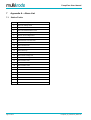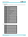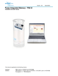
1
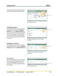
MultiTrode Web-based Pump Station Management
User Manual
PumpView User Manual
Page 2 of 54
PumpView_V5_UserManual_R05-0.doc
PumpView User Manual
This Manual is the support documentation for using the PumpView Web Interface
Document No. 00232500
PumpView Release V5
Document Revision 5-0
24 September 2009
MULTITRODE® and MULTISMART® are registered trademarks of MultiTrode Pty Ltd in Australia, USA, and Europe. PUMPVIEW® is a
registered trademark of MultiTrode Pty Ltd in the USA and Australia. Designs registered for the MultiSmart Pump Controller Remote and
Base Modules in Australia, USA, Europe and China. Patents pending in Australia, USA, and Europe. ©2009 MultiTrode Pty Ltd. This
publication is protected by copyright. No part of this publication may be reproduced by any process, electronic or otherwise, without the
express written permission of MultiTrode Pty Ltd.
PumpView_V5_UserManual_R05-0.doc
Page 3 of 54
PumpView User Manual
Contents
1
Introduction – MultiTrode PumpView ............................................................................................ 5
2
Features of PumpView Web Site V5.0 ........................................................................................... 6
3
2.1
New Features......................................................................................................................... 6
2.2
PumpView for MultiSmart....................................................................................................... 6
Login & Security.............................................................................................................................. 7
3.1
Login ...................................................................................................................................... 7
3.2
Security .................................................................................................................................. 8
4
Navigation & the Menu.................................................................................................................... 9
5
Monitoring and Controlling the System ...................................................................................... 10
6
7
Page 4 of 54
5.1
Overview page ..................................................................................................................... 10
5.2
Precedence.......................................................................................................................... 10
5.3
Region page......................................................................................................................... 11
5.4
Site Details Page ................................................................................................................. 11
5.5
Pump Control Page.............................................................................................................. 13
5.6
Monitoring page ................................................................................................................... 18
5.7
Alarms page......................................................................................................................... 29
5.8
History page......................................................................................................................... 30
Configuring the System ................................................................................................................ 37
6.1
Sites ..................................................................................................................................... 37
6.2
Organization......................................................................................................................... 46
6.3
Users.................................................................................................................................... 47
6.4
Alarming............................................................................................................................... 48
6.5
Dialout Times ....................................................................................................................... 49
6.6
Help Pages .......................................................................................................................... 50
Appendix A – Alarm List ............................................................................................................... 52
7.1
Station Faults ....................................................................................................................... 52
7.2
Pump Faults......................................................................................................................... 53
7.3
Well Faults ........................................................................................................................... 53
PumpView_V5_UserManual_R05-0.doc
PumpView User Manual
1
Introduction – MultiTrode PumpView
PumpView is a revolutionary web-based monitoring and control system. While primarily aimed at the
water and wastewater sector it can be used in a variety of industries.
Once you have installed PumpView hardware at site, you can monitor and control the site – as well as
receive alarms on your cellular phone – all via the web.
There is no software to install, no server, no radios. All you need is a web browser and an Internet
connection.
Note
Currently Internet Explorer is the primary browser supported. We have also aimed to support Mozilla
variants and test regularly using them, but full testing and verification is carried out on Internet Explorer.
Note
The PumpView website has been designed to overcome characteristic internet problems with viewing a
website from multiple browser windows simultaneously. Viewing the website via multiple browser
windows on the same PC and navigating with the Back and Forward buttons will produce stable results,
however in these circumstances critical actions may be declined by the website and the user asked to
redo the action, due to the uncertainty of what may have occurred in other windows. In this case a
warning will be shown regarding the use of actions from "stale" windows.
MultiTrode hosts the software and maintains and supports it, all for a monthly fee per site. This fee
includes the cellular data charge as well as a certain number of SMS and Voice Message (USA only)
alarms.
The system offers many of the features found in SCADA systems for a fraction of the cost.
PumpView_V5_UserManual_R05-0.doc
Page 5 of 54
PumpView User Manual
2
Features of PumpView Web Site V5.0
New features include the following:
2.1
New Features
• Dynamic “flow” menu
• Integrated “one-stop” site details page for MultiSmart
See the Installation and Commissioning manual for all site related matters.
For all the latest information on PumpView, and on all other MultiTrode products and services, visit
www.multitrode.com
2.2
PumpView for MultiSmart
PumpView Version 4 and higher has been developed to work with MultiSmart pump controllers that have
a firmware build of 1.5 or higher. If you have a previous version of the firmware the MultiSmart will still
work with PumpView, but some features will be unavailable. To access the new features the MultiSmart
can be upgraded to v1.5 or higher.
A free download of the MultiSmart firmware is available from www.multitrode.com although you will need
to first create a login and email MultiTrode for access to the firmware section.
2.2.1
PPPM2 module
V1.4 onwards of MultiSmart included an updated module for handling cellular modems. This module is
the PPPM2 module, which replaced the older PPPM module. PPPM2 offers many advantages over
PPPM in its ability to handle and recover from problems with the cellular network and its interaction with
modems.
If you are running v1.3 or earlier, or you upgraded from v1.3 to v1.4 without going through the setup
wizard, then you are probably running the original PPPM module.
How can I tell?
Go to Settings->More->More->Software Modules->Enable/Disable Modules then look and see
whether pppm is the module in the enabled column. (If you are currently running v1.3 or earlier there will
not be a reference to pppm2 in either the enabled or the disabled column).
To use pppm2 if this is not currently enabled, you must contact MultiTrode to obtain a new enable key
(you will need to tell MultiTrode your Site Code which is in Settings->More->More->Software Modules>Enable/Disable Modules->Modify).
Page 6 of 54
PumpView_V5_UserManual_R05-0.doc
PumpView User Manual
3
Login & Security
3.1
Login
PumpView is a secure system. For details about the security measures implemented behind the scenes
in PumpView, see the Security application note on our website.
All of your interaction with the PumpView website is encrypted with SSL (secure socket layer). This
means no one else can see what you are doing, or take control of your system.
Enter the web address http://www.pumpview.com in your web browser and enter your username and
password.
Figure 1 - PumpView Login Screen
To log in to the system you need a username and password. When you first become a PumpView
customer, MultiTrode issues at least one person in the organization with a username and password. That
person will be the system administrator, and, through the user interface, can add further users and
change their access level.
Note
Your username and password are the gateway into the system. It is your responsibility to choose a
password that is hard to guess, and to protect that password. It is usually a good idea to avoid your
name, names of close family members, pets’ names, and so on.
PumpView forces you to choose a password with at least 6 characters and at least 1 number. PumpView
also locks out a user after 5 incorrect password attempts. This is to protect you if someone is trying to
hack your account.
If you forget your password there is a reminder tool on the login screen to assist, however you must know
your username to use this.
Figure 2 - PumpView Login Reminder
PumpView_V5_UserManual_R05-0.doc
Page 7 of 54
PumpView User Manual
3.2
Security
There are two levels of security:
• System security
• Site security
3.2.1
System Security
System security is at two levels for the organisation: either user or administrator:
Can change their own password, and their administrative email (but not
their alarm email and phone number).
Users
Have all privileges of a user, but may also:
•
Add new users
Administrators
3.2.2
•
Change users details including their system and site permissions
(and create other users administrators, if required)
•
Change the alarm contact list for any site (PumpView supports
multiple contact lists)
•
Configure the alarm contact list and create new contact lists
•
Configure the dialout times for the different types of alarms
Site security
Each user can have different levels of security for different sites. The system administrator for the
organisation configures this. By default a new user gets the ControlHi level of site security for every site.
The different levels are:
ViewOnly
Allowed to view pages and press the "Latest data update" button
ControlLo
Allowed to Poll Site, Note/Mute PumpView Alarms, Acknowledge Site/Pump Faults
and Alarms
ControlHi
ControlLo plus change the mode of pumps into Auto /Off /Manual (Hand)
SiteAdministrator
ControlHi plus configuration of site I/O and site alarms
Page 8 of 54
PumpView_V5_UserManual_R05-0.doc
PumpView User Manual
4
Navigation & the Menu
The menu uses a dynamic “flow” style to offer the user navigation options. In addition to that a
“breadcrumb” is offered below the menu to indicate to the user their location in the system.
Figure 3 - The Menu bar and “breadcrumb”
This is the menu “at rest”. In this picture the 1st menu item LIVE allows you to monitor and control your network of
remote stations. The 2nd menu item CONFIG allows you to configure the system. The breadcrumb is showing the
user’s location upon entry to the system: >LIVE >OVERVIEW
Figure 4a - The Menu bar in action. This is showing the selection options below > LIVE
Figure 5b - The Menu bar in action. This is showing the selection options below > CONFIG
Figure 6 - In some cases, a 3rd menu level flows out to give more options.
PumpView_V5_UserManual_R05-0.doc
Page 9 of 54
PumpView User Manual
5
Monitoring and Controlling the System
Mousing over LIVE on the top menu bar gives access to the monitoring and control section of the
system.
5.1
Overview page
The default page is the Overview page that shows Regions and any Sites that have not been put into
regions.
Figure 7 - Default Overview Page
If no sites in a region have alarms, then the region gets a green tick
.
If any sites in a region are decommissioned, then the region gets a grey cross
.
If there are any alarms, including alarms that may have been cleared but not Noted on the alarms page,
there will be an alarm icon as follows:
Level Alarm
Active Alarm
Pump Unavailable Alarm
Comms Fail
You can click on a region or site icon, or you can click Region or Site on the 2nd menu bar. Creating
Regions and moving Sites into Regions is available on the > CONFIG > SITES > REGIONS page. You
can also add a Site to a Region on the > CONFIG > SITES > PUMP SITE page.
5.2
Precedence
When multiple fault and decommissioned conditions are present it is possible for the status of a
Site/Region to fit into more than one of the categories that the overview page icons refer to. In these
instances the following order of precedence is used to determine which of the icons is displayed – Site
Decommissioned (highest) Level Alarms, Comms Fails, Active Alarms and Pumps Unavailable (lowest).
Page 10 of 54
PumpView_V5_UserManual_R05-0.doc
PumpView User Manual
5.3
Region page
The > LIVE > REGION page shows the individual sites along with their alarm status, their level, and their
name. The key down the left hand side explains the alarm icons. Click on an individual site, or click the >
LIVE > PUMP SITE > PUMP CONTROL option on the menu to get into the site details.
Select Region
Drop down box
Figure 8 –Region page.
5.4
Site Details Page
The default site details page depends on the type of station selected. Currently there are a number of
types of stations:
• MultiSmart pump controller
• MultiSmart reservoir monitor
• MonitorPro & MT2PC/MT3PC pump controller
• MT2PC/MT3PC pump controller
• MonitorPro reservoir monitor
Note
The products can be used to monitor I/O in a remote site that is not either type of station,
and the I/O on the products is configurable – see Section 6.1.1 details.
The default page shown for a pump station is the Pump Control page, and for a reservoir is the
Reservoir page.
PumpView_V5_UserManual_R05-0.doc
Page 11 of 54
PumpView User Manual
5.4.1
Site Details Menu and General Information
The > LIVE > PUMP SITE menu options are as follows
Pump Control
The status and control from the pump controller –
MultiSmart or MT2PC/MT3PC
Monitoring
Flow data, supply voltage, currents, power,
energy, insulation resistance test, and
accumulators – where the appropriate module is
enabled in the MultiSmart – or with the older
product family, when a MonitorPro is installed.
Reservoir
The status and control from a reservoir.
I/O controls
General purpose I/O from this site.
All details
Every I/O point and tag from this site in one page.
Notes
All previous site notes are recorded here.
Figure 9 – Pump Site Menu
Organization
Name of the organization.
Customer
Locale/Flag
This refers to the country and time zone of the
customer, not the site. See note below for further
detail.
Login
Name of the currently logged in user.
System Level
This shows your permissions for configuring the
system. See section 3.2.1 for details.
Site Level
This shows your permissions for controlling sites,
resetting and noting alarms and setting up I/O. See
section 3.2.2 for details.
Figure 10a - Login Details Panel
Site
Level
This shows your
permissions for
controlling sites,
resetting and noting
alarms and setting up
I/O. See section 3.2.2
for details.
Figure 11b – Login Site Permission Details Panel
Note
Customer Locale – This refers to the country and time zone of the customer, not site. If the site has a
different country and time zone setting to that of the customer then the time zone and/or national flag
for the site will be displayed next to the site name. If there is no time zone / country difference
between customer and site (the normal case) then the time zone information and/or national flag is not
displayed next to the site name (so as to avoid screen clutter).
Page 12 of 54
PumpView_V5_UserManual_R05-0.doc
PumpView User Manual
5.5
Pump Control Page
The Pump Control page relates to a MultiSmart or MT2PC family at site and shows level, pump mode,
pump faults, level alarms, communications faults, and accumulators. The screen changes depending on
whether the pump controller is a MultiSmart or an MT2PC family product.
The MultiSmart must be upgraded to v1.5 or later for this functionality below.
5.5.1
MultiSmart Pump Control Page
Select Site
Drop down box
Figure 12 –MultiSmart Pump Control Page for a 2-pump system
The MultiSmart pump control page has controls for:
Poll Site - request data from the remote site
Refresh Page (Latest Data update) - updates the page you are viewing from the PumpView database.
The PumpView database is updated periodically from the field.
Note
Alarms are sent immediately, regardless of the update rate.
PumpView_V5_UserManual_R05-0.doc
Page 13 of 54
PumpView User Manual
Select (next to Hand=Manual, Off and Auto) - change the mode of the pump.
Reset Pump Alarms - reset a pump fault. The reset option only appears when a fault occurs. Resets can
only happen when the pump fault condition is no longer present.
Reset Well Alarms - reset a level alarm. This can only happen when the level alarm condition is no
longer present.
Reset Site alarms - this appears under Station Faults if any overall station faults are present – e.g.
• Under Voltage
• Over Voltage
• Volts Phase Imbalance
• Volts Phase Rotation
• DC Under Voltage
• DC Over Voltage
• Maximum Runtime Fault
• Maximum Off Time Fault
• Power Fail
• Overflow
• Pulse Start/Stop Fault
• DSP (inter-unit) Comms Fault
Note
Resetting faults and alarms will also clear the alarm on the faceplate of the field hardware.
This will not clear the alarm from the alarm page until it is noted there.
Setpoint Profile – select a new setpoint profile from a dropdown list. Profiles are stored within the
MultiSmart. Standard profiles include Default, Spill Management and Gen Set/Load Shedding.
Site Notes - Editing notes can be done by clicking in the site notes box and starting to add some text, or
replace text. As soon as a change is made, an Update Notes button appears which is used to save the
text changes.
5.5.1.1
Communications Faults
Comms fail to site means cellular communications problems. This
could be due to the cellular carrier’s traffic congestion (data
pathways can congest even while voice and wap/www is still
available), dirty modem/SIM contacts, modem malfunction, or due to
insufficient gain from the antenna.
A Comms Fail alarm is raised 122 minutes (default, settable) after a
failed site poll is detected. Sites are polled on an hourly basis, so this
means two consecutive polls must fail before the alarm is raised.
Figure 13 – Shows a comms fail to site.
Page 14 of 54
PumpView_V5_UserManual_R05-0.doc
PumpView User Manual
Figure 14 – Sample pump control screen for a MultiSmart with four pumps and two wells
PumpView_V5_UserManual_R05-0.doc
Page 15 of 54
PumpView User Manual
5.5.2
MT2PC Pump Control Page
The MT2PC family of products has a similar Pump Control page to MultiSmart, but not identical. It is
specifically orientated around the Pump Control page representing the functionality present in the
MT2PC/MT3PC and the Monitoring page representing the functionality present in the MonitorPro.
Figure 15 – MT2PC Pump Control Page
The MT2PC page has controls for:
Poll Site - request data from the remote site
Refresh Page (Latest Data update) - updates the page you are viewing from the PumpView database.
The PumpView database is updated periodically from the field.
Note
Alarms are sent immediately, regardless of the update rate.
Page 16 of 54
PumpView_V5_UserManual_R05-0.doc
PumpView User Manual
Select (next to Hand=Manual, Off and Auto) - change the mode of the pump.
Reset Pump 1 (2 or 3) - reset a pump fault. This can only happen when the pump fault is
unacknowledged and not present.
Note
This will also clear the fault on the faceplate of the field hardware.
Reset Alarms - reset a level alarm. This can only happen when the level alarm is unacknowledged and
not present.
Note
This will also clear the fault on the faceplate of the field hardware.
This will not clear the alarm from the alarm page until it is noted there.
The Faults shown on this controller page relate to the faults that are available with the MT2PC or
MultiSmart. The Monitoring page shows additional info from the MultiSmart or from a MonitorPro (if
installed) e.g. motor protection faults, as well as motor currents, 3-phase supply, flow, etc.
The pump controller I/O can be configured. This is done through the > CONFIG menu.
Peak Levels - move the MT2PC into "peak levels". This is the separate set of levels within the product
that can be used for spill management, energy management, etc.
Note
If the Peak Level input is connected to ground at site, the Peak Level condition cannot be turned off
from the PumpView interface.
Site Notes - Editing notes can be done by clicking in the site notes box and starting to add some text, or
replace text. As soon as a change is made, an Update Notes button appears which is used to save the
text changes.
5.5.2.1 Communications faults
There are 3 types of comms faults:
Network Comms – cellular communications problems. This could be due to the cellular carrier, or the
modem, or due to insufficient gain from the antenna.
PumpView Comms – the connection from the PumpView hardware to the MT2PC/MT3PC or
MonitorPro. This means that PumpView can talk to the PumpView hardware but the PumpView hardware
cannot communicate with the other MultiTrode equipment. Check cables and the device that PumpView
is connected to.
LAN Comms – for MT2PC/MonitorPro installations only. The connection between the MT2PC/MT3PC
and the MonitorPro if both are connected. Check cables. Check the setup of MT2PC/MT3PC, EDS44.
Check the setup of the MonitorPro.
PumpView_V5_UserManual_R05-0.doc
Page 17 of 54
PumpView User Manual
5.6
Monitoring page
Click on the Monitoring link in the left hand menu pane to get to the monitoring page. The pages will
have different data depending on whether the site has a MultiSmart or the MT2PC/MonitorPro family.
5.6.1
MultiSmart
The monitoring page displays a wider set of information for the MultiSmart. Faults and alarms are
summarised at the top of the page. Extensive monitoring data is listed down the page for the following
areas:
•
Event Accumulators
•
Flow Information
•
Electrical Supply
•
Power
•
Energy
•
Protection
Note
MultiSmart v1.5 firmware (or higher) must be installed in the device before this information can be
viewed.
Figure 16 - MultiSmart Monitoring Page
Additional data is obtained by clicking on the lightened “tabs” along the top of the data panel: EVENT,
FLOW, EFFICIENCY, SUPPLY, VFD SPEEDS
Page 18 of 54
PumpView_V5_UserManual_R05-0.doc
PumpView User Manual
Figure 17 – MultiSmart Monitoring Page (continued) These panels are duplicated onto the >LIVE >PUMP SITE >
PUMP CONTROL page for convenience.
Figure 18 – MultiSmart Monitoring Page (continued)
PumpView_V5_UserManual_R05-0.doc
Page 19 of 54
PumpView User Manual
Figure 19 – MultiSmart Monitoring Page (continued)
Page 20 of 54
PumpView_V5_UserManual_R05-0.doc
PumpView User Manual
Figure 20 – MultiSmart Monitoring Page (continued)
Figure 21 – MultiSmart Monitoring Page (continued)
PumpView_V5_UserManual_R05-0.doc
Page 21 of 54
PumpView User Manual
5.6.2
MT2PC/MonitorPro family
With this family of products, the Monitoring page represents all of the MonitorPro data and controls, so
this page includes any motor protection faults.
As well as repeating some information from the Controller page, (see Section 5.5), this page also
includes the faults from the MonitorPro –see the screenshot for the list.
The MonitorPro/MultiSmart data is also shown on this page (see Section 2.2):
•
3-phase supply voltages
•
Insulation resistance
•
DC supply voltage
•
Overflow data (if any)
•
3-phase currents for each pump
•
Flow data, inc. inflow, pump flow rates, etc
If no MonitorPro is installed with the MT2PC, the monitoring page will indicate this fact.
Figure 22 - MonitorPro Page - Status area
Page 22 of 54
PumpView_V5_UserManual_R05-0.doc
PumpView User Manual
Figure 23 – MonitorPro Page – Data Area
PumpView_V5_UserManual_R05-0.doc
Page 23 of 54
PumpView User Manual
5.6.3
Reservoir page
If a reservoir site is selected a Reservoir link will appear in the left hand menu pane.
A reservoir is monitored using a MultiSmart (or a MonitorPro) at site. The level from the reservoir is
communicated, via the PumpView server, to pump stations that pump into it.
The level displayed on those pump station(s) will be the level at the reservoir. This is also true of the
faceplate of the field hardware.
NOTE:
The site can be changed using the Select Site drop down box on the right hand side under the
MultiTrode logo.
Select Site
Drop down box
Figure 24 – MultiSmart Reservoir Page
Page 24 of 54
PumpView_V5_UserManual_R05-0.doc
PumpView User Manual
Select Site
Drop down box
Figure 25 – Monitor Pro Reservoir Page
PumpView_V5_UserManual_R05-0.doc
Page 25 of 54
PumpView User Manual
5.6.4
I/O Controls page
The I/O Controls page shows the current status of the digital and analog I/O on the pump controller or
MonitorPro. The I/O is configurable via the > CONFIG menu (see Section 6.1.1).
Note
Specific I/O can also be assigned as alarms.
5.6.4.1 MultiSmart
Sites with MultiSmart v1.5 or higher will see the following page:
Figure 26 – MultiSmart I/O Page
Page 26 of 54
PumpView_V5_UserManual_R05-0.doc
PumpView User Manual
5.6.4.2 MT2PC
Sites with a MT2PC pump controller will see the following page:
Figure 27 – MT2PC/MonitorPro I/O Page - Pump Controller I/O
The example page here shows the configurable I/O with some user-defined names. Additionally, the
MT2PC/MT3PC has a number of specific inputs that can be used in their “out of the box” mode, or
assigned as general telemetry inputs.
EDS70-88 on the pump controller needs to be used to set these inputs up in the field before they can be
used here. To allow these digital outputs to be remotely controlled, EDS 51-55 need to be set to the
value of 32. For more information see the MT2PC/MT3PC product manual.
PumpView_V5_UserManual_R05-0.doc
Page 27 of 54
PumpView User Manual
5.6.4.3 MonitorPro
For Sites which have a Monitor Pro, the following I/O is also visible.
Figure 28 - I/O Page - Monitor Pro I/O
Page 28 of 54
PumpView_V5_UserManual_R05-0.doc
PumpView User Manual
5.7
Alarms page
The alarms page contains a summary of the alarms across the entire network.
Figure 29 - Alarms Page
The key on the right hand side explains the alarming states.
Alarms are Muted by replying to the SMS, email or voice (USA only) alarm.
Alarms are Noted by clicking them on this Alarms page screen. (Noting an alarm also will also Mute the
alarm if the user has not previously done this).
If there has been an alarm at site that has cleared and been reset at site, but never Noted it will stay on
this page. The site icon will also display the alarm. This is to ensure that operations personnel are
alerted to alarm conditions even if onsite personnel have reset the alarm.
The following screen shows the Thermal Fault alarm being Noted.
Figure 30 - Noted Thermal Fault Alarm
PumpView_V5_UserManual_R05-0.doc
Page 29 of 54
PumpView User Manual
5.8
History page
The history page allows the user to plot trends on a Preview screen, as well as request an email of the
CSV files with the selected data. CSV files can be opened in MS Excel, which has a wide range of
options for then massaging the data into graphs and reports.
History can be generated by region or sites, or a combination of both. Altering the Regions selector will
affect the Sites selector state. (The final contents of the Sites selector determines which Site Trend
points are included.)
To generate by region, simply select one or multiple Available regions and click on
the sites within the selected region(s).
To generate by site, select one or multiple Available sites and click on
. This will select all
.
To generate by regions and select additional sites follow both steps above.
To remove sites, select one or multiple Selected sites and click on
.
Now select the desired Available tag(s) for which the history is being retrieved and click on
Page 30 of 54
.
PumpView_V5_UserManual_R05-0.doc
PumpView User Manual
Finally, select the start and finish dates using the buttons for the pop-up calendars, or by typing dates into
the text fields (note that the format must be correct as per the examples given).
Figure 31 - Hourly and Daily History Selection Page
PumpView_V5_UserManual_R05-0.doc
Page 31 of 54
PumpView User Manual
Press Preview to show the on screen graph of the selected data.
The following image shows the resulting Hourly and Daily Graph from the previous selection.
Figure 32 - Daily Data Preview
Page 32 of 54
PumpView_V5_UserManual_R05-0.doc
PumpView User Manual
The following image is of the Hourly and Daily Graph for a shorter time selection, where the data spacing
is now able to be hourly.
Figure 33 - Hourly Data Preview
PumpView_V5_UserManual_R05-0.doc
Page 33 of 54
PumpView User Manual
If the preview of the data is acceptable press Email to email the data to your administrative email address
in .csv format.
Figure 34 - History Emailed feedback
Note
Each user has an administrative email address, which can be configured differently to their alarming email
address.
The Historical Selection in the 3rd menu permits Trending of another set of data that is recorded "On
Change", rather than accumulated on an hourly or daily basis.
The following image shows the selection form for the Historical Graph.
Figure 35 - Historical (On-Change) History Selection Page
Page 34 of 54
PumpView_V5_UserManual_R05-0.doc
PumpView User Manual
The following image shows the resulting Historical Graph from the previous selection.
Figure 36 - Long-term Historical (On-Change) History Preview
The following image is of the Historical Graph for a shorter time selection.
Note
The axis data spacing is now hourly, but the data is the same (aperiodic).
PumpView_V5_UserManual_R05-0.doc
Page 35 of 54
PumpView User Manual
Figure 37 - Short-term Historical (On-Change) History Preview
Page 36 of 54
PumpView_V5_UserManual_R05-0.doc
PumpView User Manual
6
Configuring the System
The CONFIG section of the menu gives access to a number of configuration options.
For example, the menu used for configuring Sites is as accessed as follows:
Configuration is limited by your security access, see Section 3.2.
6.1
Sites
Access to this section is via > CONFIG > SITES > PUMP SITE
6.1.1
Adding a Site
From the > CONFIG > SITES > PUMP SITE location, click the “Add New Site” Tab
When supplying you with new PumpView hardware, MultiTrode support will initialise the new hardware
and allocate it to your pool of available sites to add to your system configuration.
To add a new site:
• If you wish to copy any of the configuration of an already configured site to the new site then:
o
Select the desired RTU type for the new site (noting that this is not explicitly recorded in the new
site's setup data, it is used to alter the selection of typical sites to copy from in the following
step).
o
Select the site to copy settings from.
o Select the configuration settings that should be applied (see explanatory list below)
• Select the desired unused site from the drop down list (the unused site will be identified by a 4 digit
number corresponding to the first 4 digits in the product serial number).
• Click "Add a New Site"
Not Applicable to
MultiSmart v1.5+
Figure 38 Adding a new site
PumpView_V5_UserManual_R05-0.doc
Page 37 of 54
PumpView User Manual
•
Copy the basic details – Sets the site type (sewer or water), time zone, locale, RTU type (MTxPC, MonPro or
ResMon) and the number of pumps of the new site to match the existing site.
•
Copy the region details – Sets the new site’s region membership to an existing site’s membership
•
Copy the I/O Points – Sets the configurable names and scaling factors of the new site’s I/O Points to match
the setup of the existing site. Not applicable to MultiSmart (V1.5 and onwards) sites.
•
Copy the Alarm Points – Duplicates the alarm point configuration of the existing site at the new site. Not
applicable to MultiSmart (V1.5 and onwards) sites.
•
Copy the Alarm Contacts – Sets the alarm contact list at the new site to match that of the existing site.
Note 1
Once a site has been added, it must be commissioned before it will communicate with the PumpView
Server (see Section 7.1.1.3).
Note 2
It is not currently possible to copy I/O and Alarm Points from a site using a MultiSmart (V1.5 and
onwards) pump controller. This is due to the user-configurable tag structure of the device.
6.1.2
Site Details
This section allows you to modify a site’s basic configuration details.
Figure 39 – Updating a site's basic configuration details
•
Site Name – Set the display name of the site.
•
Site Location – Set the location of the site.
•
Site Type – The type of site (either Sewer or Water).
•
RTU Type – The type of RTU that the PumpView hardware is connected to.
•
Remote Set Level Reservoir Source – Enable a booster pump station to receive its level remotely from a
reservoir site.
•
Contact List – The contact list to be used when alarm conditions occur.
•
Locale – The locale settings for the site (this will impact upon the display of dates/times within PumpView).
•
Time Zone – The time zone settings for this site (this will allow PumpView to render date/time information into
the correct time zone).
Page 38 of 54
PumpView_V5_UserManual_R05-0.doc
PumpView User Manual
Note
If changing the RTU Type, the site must be decommissioned first. Then the RTU type can be changed
and the site details updated. Remember to re-commission the site after the RTU Type has changed.
6.1.2.1 Commission / Decommission
A site can be commissioned or decommissioned. A decommissioned site cannot alarm and will not allow
the user to send poll or command requests to the remote site.
To commission a site for the first time, ensure that the PumpView hardware has been turned on. When
the PumpView hardware has successfully communicated with the PumpView Server the Commission
button will become available.
6.1.2.2 Site Region Membership
To assign a site to a region select a region from the Available list and press Include. A site can be the
member of multiple regions.
To remove a site from a region select a region from the Selected list and press Remove.
Once the region membership selection has been completed, press Update Site Regions for the changes
to take effect.
Figure 40 – Editing a Site’s Region
PumpView_V5_UserManual_R05-0.doc
Page 39 of 54
PumpView User Manual
6.1.3
Regions
The Edit Region screen has four tabs:
•
Edit Regions’ Details
•
Edit Region’s Sites
•
Delete Regions
•
Add New Region
Figure 41 – Edit Regions Screen
6.1.3.1 Updating / Deleting a Region
A region’s name can be changed by editing the name and pressing Update Changed Regions.
A region can be selected as the default region by checking the radio button next to the desired region and
pressing Update Changed Regions.
Note
The default region is selected if a user presses the region button without having previously selected a
region within the system.
One or more regions can be deleted by checking the box next to the selected regions and pressing
Delete Selected Regions.
Note
Deleting a region does not delete the sites within that region.
Page 40 of 54
PumpView_V5_UserManual_R05-0.doc
PumpView User Manual
Figure 42 Deleting Regions
6.1.3.2 Member Sites for a Region
To add member sites for a region, select the desired region from the drop-down menu. Now select the
site(s) that are to members of the region from the Available list. Multiple sites can be selected using the
Shift or Ctrl keys. Press Include to select the sites and then Update Region Sites for the changes to
take effect.
To remove member sites for a region, select the region to be removed from the Selected list and press
Remove then Update Region Sites for the changes to take effect.
The order in which sites are displayed on a region overview page can be modified by selecting the
required site(s) and pressing Move Site(s) Up or Move Site(s) Down. Press Update Region Sites for
the changes to take effect.
Figure 43 – Updating the sites that belong within a region
PumpView_V5_UserManual_R05-0.doc
Page 41 of 54
PumpView User Manual
6.1.3.3 Adding a Region
To add a new region, enter a name for the new region and press Add New Region. The new region is
now available for selection as the default region and can be assigned member sites.
Figure 44a Add a new region
6.1.4
Accumulators
PumpView Accumulator values cannot be changed for a MultiSmart. For Monitor Pro installations the
following screen is provided for altering Accumulator values stored in the Pumpview data server.
Figure 45b Update Accumulators
To alter an accumulator, enter the required value and click “Update”. This may be zero or any other
number.
6.1.5
I/O Points
I/O points can be configured through Pump View provided the points have been set in the controller to
allow control via telemetry.
All of the general purpose I/O can be renamed, scaled in the case of analogs, and made to be an alarm
point if required.
Note 1
You must click the Update I/O button to save any changes.
Note 2
If an input is reassigned, it will no longer perform its original function, i.e. the AC input will cause a
security fault, but will not cause a pump 1 critical fault and will not affect the pump control.
Page 42 of 54
PumpView_V5_UserManual_R05-0.doc
PumpView User Manual
6.1.5.1 MultiSmart
The MultiSmart I/O pages are divided in Control I/O points and Monitoring I/O points. These are then
divided into Physical and Standard I/O.
•
Control I/O are points used to control pumps in a site.
•
Monitoring I/O are points used to monitor the Well and Site.
•
Physical I/O are the physical analog and digital inputs and outputs found on the MultiSmart itself.
•
Standard I/O are points that are measured or interpreted.
Figure 46 – MultiSmart I/O Config Page
To allow points to be remotely controlled they must be set on the MultiSmart to Remote Source. Refer to
the MultiSmart product manual.
PumpView_V5_UserManual_R05-0.doc
Page 43 of 54
PumpView User Manual
6.1.5.2 MT2PC/MonitorPro
The MT2PC/MonitorPro pages are divided between Control I/O and Monitoring I/O. These are then split
between Analog, Physical and Standard I/O.
•
Control I/O is used to control pumps and are located on the MT2PC pump controller.
•
Monitoring I/O is used to monitor the well/site and is located on the MonitorPro.
•
Physical I/O is the digital inputs and outputs located on the MT2PC or MonitorPro itself.
•
Analog I/O is the analog inputs and outputs located on the MT2PC or MonitorPro itself
There is some standard configurable I/O on the MT2PC/MT3PC, (in the product keys on the page we call
this the xPC) and on the MonitorPro. These appear on this page by default, e.g. for the MT2PC it is DO1,
DO2, DO3, DO4, DO5.
To allow these digital outputs to be remotely controlled, EDS 51-55 need to be set to the value of 32. For
more information see the MT2PC/MT3PC product manual.
The MT2PC also has a number of specific I/O which by default has a meaning, e.g. AC = critical fault
input, pump 1. Using EDS70-88 on the MT2PC itself, the user can change these inputs to be generalpurpose telemetry inputs.
They can then be customised in PumpView so that they appear on this page. For example, the 'AC'
Digital Input could be renamed "Security", wired to a security input, and created as an alarm tag.
6.1.5.3 Copying I/O Points
Use the Select box to checkmark I/O Points and tags to copy to other sites.
Figure 47 – I/O Setup with option to copy the site configuration to other sites.
Note
A extra I/O is shown for Monitor Pro or MultiSmart equipped sites
Page 44 of 54
PumpView_V5_UserManual_R05-0.doc
PumpView User Manual
6.1.6
Alarm Points
Each alarm point can be configured, including the I/O or tags that have been assigned as alarms in the
I/O Points page.
Figure 48 - Alarm Points
Analog I/O Alarms - requires entering upper and lower limits of allowable values, (i.e. an alarm condition
is active for an analog I/O points if the I/O point value < lower limit OR I/O point value >= upper limit.
You can select whether the alarm is activated when a digital point goes high or low, whether the alarm is
a dial out alarm or an info alarm, how many retries on dialling, and the timeout between the dial-out.
There are certain defaults, of course, to make the setup easier.
Dial Out vs. Info Alarm - an Info alarm only shows the alarm on the summary alarm page, whereas a
Dial Out alarm also starts contacting users according to the alarm contact schedule.
Contact Retries - this setting governs how many times the entire alarm contact list is contacted after the
first time (i.e., set this value to 1 for the entire contact list to be contacted twice).
Contact Timeout - time in minutes between each contact attempt.
Alarm Priority - allows you to set higher priority alarms to always dial out, and less urgent alarms to dial
out only at more reasonable hours. The alarm priorities can be setup by clicking Alarming on the lower
menu bar, followed by Dialout Times in the left hand menu pane.
Re-alarm enable and timeout - set this if you want the alarm notification system to recommence
notifying users of an alarm condition if it remains present for a certain period of time (minutes), after the
alarm has been muted or noted. The minimum time is 10 minutes, with a typical time of >1 hour.
PumpView_V5_UserManual_R05-0.doc
Page 45 of 54
PumpView User Manual
6.1.7
Alarm Contacts
You can select different contact lists for different sites. Alarm lists are set up using the > CONFIG >
ALARMING selection in the menu.
Figure 49 – Setting up Alarm Lists for specific sites
6.2
Organization
As the Administrator you can modify the contact details for the organization and enable/disable the
reports that are emailed daily from the PumpView website.
Figure 50 Configuration of organisational details and reporting configuration
Page 46 of 54
PumpView_V5_UserManual_R05-0.doc
PumpView User Manual
Contact Name / Address / Phone – The contact details to be used by MultiTrode to contact customers
to alert them of important items relating to PumpView.
Locale / Time Zone – The time zone and locale settings will be used to correctly render date/time values
in the reports.
Reports Enabled – Enable/disable the sending of daily reports (including pump statistics, fault logs, user
interaction logs and alarm logs) via email.
Reports Email Address – The email address that shall receive the daily email reports.
6.3
Users
As the Administrator you can add users, select users and change their details and permissions, as well as
amend your own details. See Section 3.2 for details on security privileges.
6.3.1
Changing User’s Details
If you are an administrator you can select a user from the right hand side drop down box, and amend their
details.
Select User from
drop-down box
Figure 51 - User Details Page
Note
Each user has an administrative email address, (e.g. for being sent lost passwords, reports, etc) and an
alarm contact email address. These can be the same or different, as you set them.
PumpView_V5_UserManual_R05-0.doc
Page 47 of 54
PumpView User Manual
6.3.2
Add a New User
Go to the Add New User tab to add a user.
Note
Usernames can not have spaces – you also get the opportunity to enter their full name once you have
clicked the Add New User button.
Figure 52 - Add a New User
6.4
Alarming
This menu option opens up two further options in the left hand menu pane.
6.4.1
Alarm Lists
This option allows you to set up the alarm lists, change the order of users, and add a new list.
Note
Each user has multiple contact methods (if these have been added to their details): email, SMS, and
voice (USA only).
Figure 53 - Alarm Lists Page
Note
PumpView has no direct support for pagers, but many paging companies have email gateways. Contact your pager
provider for details on their email gateway then set the pager users up as email recipients, e.g. pager
[email protected]
Page 48 of 54
PumpView_V5_UserManual_R05-0.doc
PumpView User Manual
6.5
Dialout Times
This page allows you to create different priorities for different alarms. You then assign alarm points to
these priorities (via > CONFIG > SITES > ALARM POINTS –see section 6.1.6).
For example, you might want all high-level alarms to be a 24/7 dial out. However, if a pump has a critical
fault, you might want to be notified between 6am - 10pm so you can be informed if you are awake, but not
woken if you are asleep. Other alarms, like a seal fault alarm you might only want to notify you during
working hours. The choice is yours, and you can add as many alarm priority types, as you like.
Note
If an alarm does not dial out, it still appears on the alarms page with an Info alarm icon.
Figure 54 - Dialout Times Page
PumpView_V5_UserManual_R05-0.doc
Page 49 of 54
PumpView User Manual
6.6
Help Pages
There is an online help system in place as an additional aid in use of Pumpview
The Help item in the menu is a link to specific help content for the page currently selected (as shown in
the “breadbrumb”), ie: in the following image there are 2 Help items available, one for the selected page:
> CONFIG > USERS > USER, and one for extra information on the Password selection.
Help links
Figure 55 - Help links in the menu and embedded in the site.
Following is the Help content from the menu above.
Figure 56a - Help Page for the 1st menu
Page 50 of 54
PumpView_V5_UserManual_R05-0.doc
PumpView User Manual
Figure 57b - Help Page for embedded link.
PumpView_V5_UserManual_R05-0.doc
Page 51 of 54
PumpView User Manual
7
Appendix A – Alarm List
7.1
Station Faults
1
Site Under Voltage Fault
2
Site Over Voltage Fault
3
Site Volts Phase Imbalance Fault
4
Site Volts Phase Rotation Fault
5
Site DC Under Voltage Fault
6
Site DC Over Voltage Fault
7
Site Maximum Runtime Fault
8
Site Maximum Off Time Fault
9
Site Power Fail Fault
10
Site Overflow Fault
11
Site Pulse Start
12
Site Pulse Stop
13
Site DSP (inter-unit) Comms Fault
14
Site Current Config Fault
15
Site Previous Config Fault
16
Site General Fault 1
17
Site General Fault 2
18
Site General Fault 3
19
Site General Fault 4
20
Site General Fault 5
21
Site General Fault 6
22
Site General Fault 7
23
Site General Fault 8
24
Site General Fault 9
25
Site General Fault 10
Page 52 of 54
PumpView_V5_UserManual_R05-0.doc
PumpView User Manual
7.2
Pump Faults
These faults are pre-defined within MultiSmart, but a typical site would only have a subset of these faults
enabled.
7.3
1
Pump Seal Fault
2
Pump Thermal Overload Fault
3
Pump Flygt Seal Fault
4
Pump Flygt Thermal Fault
5
Pump CLS Seal Fault
6
Pump Ground (Earth) Fault
7
Pump Insulation Resistance Testing Fault
8
Pump Amps Phase Imbalance Fault
9
Pump Amps Phase Rotation Fault
10
Pump Under Current Fault
11
Pump Over Current Fault
12
Pump Contactor Aux
13
Pump Delay Fail
14
Pump Motor Temperature Fault
15
Pump CB Trip Fault
16
Pump Max Starts Fault
17
Pump High Flow Fault
18
Pump Low Flow Fault
19
Pump Critical Fault
20
Pump Non-Critical Fault
21
Pump Pulse Start
22
Pump Pulse Stop
Well Faults
1
Well High High Level Fault
2
Well High Level Fault
3
Well Low Level Fault
4
Well Low Low Level Fault
5
Well Primary Level High Range
6
Well Primary Level Low Range
7
Well Primary Level Invalid Fault
8
Well Primary Level Ain Over Range
9
Well Backup Level Ain Under Range
10
Well Pulse Start
11
Well Pulse Stop
PumpView_V5_UserManual_R05-0.doc
Page 53 of 54
PumpView User Manual
MultiTrode Pty Ltd—UK Operations MultiTrode Pty Ltd—Head Office
Ivybridge, Devon
Brisbane QLD
MultiTrode Inc—USA
Boca Raton Florida 33487
Tel: +44 1752 547355
Fax: +44 1752 894615
61 7 3340 7000
Fx: +61 7 3340 7077
Tel: +1 561 994 8090
Fax: +1 561 994 6282
E-mail:[email protected]
E-mail: [email protected]
E-mail: [email protected]
Visit www.multitrode.com for the latest information
Page 54 of 54
PumpView_V5_UserManual_R05-0.doc