1
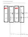
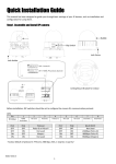
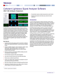
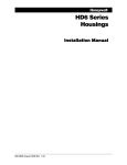
I R T Electronics Pty Ltd A.B.N. 35 000 832 575
26 Hotham Parade, ARTARMON N.S.W. 2064 AUSTRALIA
National: Phone: (02) 9439 3744
Fax: (02) 9439 7439
International:
+61 2 9439 3744
+61 2 9439 7439
Email: [email protected]
Web: www.irtelectronics.com
IRT Eurocard
Types
VA-531
Serial data subcarrier modulator
&
VA-581
Serial data subcarrier de-modulator
Designed and manufactured in Australia
IRT can be found on the Internet at:
http://www.irtelectronics.com
IRT Eurocard
Types
VA-531
Serial data subcarrier modulator
&
VA-581
Serial data subcarrier de-modulator
Instruction Book
Table of Contents
Section
General description
Technical specifications
Technical description
Operational safety
Pre-installation
Internal adjustments
Installation
Front & rear panel connector diagrams
Maintenance & storage
Warranty & service
Equipment return
Drawing index
This instruction book applies to units later than S/N 9512000.
Page
3
4
5
6
6
7
8
9
10
10
10
11
GENERAL DESCRIPTION
The VA-531 is an IRT Eurocard serial data modulator and the VA-581 is the matching de-modulator.
Two interfaces are provided, one conforming to the “RS232” standard and the other to the “RS422” standard. The
RS232 input and output is via a 9 pin ‘D’ connector and the RS422 input and output is via a 15 pin ‘D’ connector.
Selection of the active signal input on the VA-531 data modulator is done by an internal link. In the asynchronous
mode both the outputs from the VA-581 data demodulator are simultaneously available.
The special case of the synchronous 192 Kbit mode is only available via the RS422 connectors. In this mode the
user provides data and clock and the VA-531 uses a Manchester code modulator to encode the transmitted signals.
Whilst primarily intended to function as part of an IRT fibre optic system the VA-531 & VA-581 may also be used
for other applications where it is desired to include serial data modulated subcarriers in the video signal.
The VA-531 generates a subcarrier frequency, which is modulated by the incoming serial data signal using the
Frequency Shift Keying method (FSK). The VA-581 detects the particular subcarrier frequency and de-modulates it
to obtain the original serial data signal.
The modules must be supported by a subcarrier / video combiner (or splitter at the receiver end ) and Low Pass
Filter. These may be on a separate module (VA-520 / VA-570) or as an integral part of a fibre optic video
transmitter / receiver (AVT-3070 / AVR-3070, AVR-3071).
Various subcarrier frequencies are available including 9.1 MHz, 9.6 MHz & 11.7 MHz. Further frequencies may be
available allowing several module to have their outputs combined for multichannel applications.
Standard features:
•
•
•
•
•
RS232 or RS422 operation.
Asynchronous operation to 38 Kbaud
Synchronous RS422 operation at 192 Kbaud
Suitable for use with fibre optic and microwave links.
Multiple modules may be linked using active subcarrier loop through connection.
Equipment provided:
Standard:
VA-531:
VA-581:
Optional:
VA-531 Serial data modulator module.
RB-531 Rear assembly for VA-531.
VA-581 Serial data modulator module.
RB-581 Rear assembly for VA-581.
CA-5VID BNC-BNC linking cable for connecting subcarrier to
adjacent module.
Accessories available:3RU Eurocard module mounting frame:-
Provides mounting for up to 12 Eurocard modules
and one Dual AC power supply side by side or up to
10 Eurocard modules and two hot pluggable AC
supplies side by side in 134 mm of standard Rack
space (3 Rack Units).
1RU chassis conversion/PSU
Provides a means of converting Eurocards to a 1
rack unit format. The 1RU frame can be fitted with
either one or two Eurocards in a horizontal side by
side format. A single AC power supply is included
to power the cards.
TME-6 Eurocard extender board.
Instruction Book.
TECHNICAL SPECIFICATIONS
IRT Eurocard modules
Types VA-531 / VA-581
RS232:
Connector
Nominal input / output level
Maximum data rate
9 pin ‘D’ female.
±9 V minimum.
38 Kbaud (asynchronous mode only).
RS422:
Connector
Input impedance
Input threshold level
Output level
Maximum data rate
15 pin ‘D’ female.
150 Ωbalanced
200 mV differential
(for a common mode of -7 to +12 V).
5 V unloaded (differential)
>2 V (50 Ω load) (differential).
192 Kbaud synchronous mode
38 Kbaud asynchronous mode.
Subcarrier:
Type
Impedance
Nominal input / output level
Frequency (factory set according to application)
Standard
Other:
Power Requirements:
Power consumption
DC coupled.
75 Ω.
60, 100 or 240 mVp-p (factory set according to
application).
One of the following.
9.1 MHz, 9.6 MHz or 11.7 MHz
Consult factory.
28 Vac CT (14-0-14) or ± 16V DC
<5 VA
Other:
Temperature range
Mechanical
Finish:
Front escutcheon
Rear assembly
Dimensions
Optional accessories
0 - 50° C ambient
Suitable for mounting in IRT 19" rack chassis types
with input, output and power connections on the rear
panel
Grey enamel, silk screened black lettering & red
IRT logo
Detachable silk screened PCB with direct mount
connectors to Eurocard and external signals
6 HP x 3 U x 220 mm IRT Eurocard
Instruction manual
TME-6 module extender card
TECHNICAL DESCRIPTION
IRT Eurocard
Serial data Modulators & Demodulators.
The VA-531 is an IRT Eurocard serial data modulator and the VA-581 is the matching de-modulator.
Whilst primarily intended to function as part of an IRT fibre optic system they may also be used for other
applications where it is desired to include serial data modulated subcarriers in the video signal.
The VA-531 generates a subcarrier frequency which is modulated by the incoming serial data signal using the
Frequency Shift Keying method (FSK), similar to the method used for FM sub-carrier audio channels. The VA-581
detects the particular subcarrier frequency and de-modulates it to obtain the original serial data signal.
The modules must be supported by an subcarrier / video combiner (or splitter at the receiver end ) and Low Pass
Filter. These may be on a separate module (VA-520 / VA-570) or as an integral part of a fibre optic video
transmitter / receiver (AVT-3070 / AVR-3070, AVR-3071).
With the standard operating frequency and filters the data transfer rate for asynchronous operation is a maximum of
38 Kbit. For synchronous operation the data rate is exactly 192 Kbit.
Two interfaces are provided, one conforming to the “RS232” standard and the other to the “RS422” standard. The
RS232 input and output is via a 9 pin ‘D’ connector and the RS422 input and output is via a 15 pin ‘D’ connector.
Selection of the active signal input on the VA-531 Data Modulator is done by an internal link. In the asynchronous
mode both the outputs from the VA-581 Data Demodulator are simultaneously available.
The special case of the synchronous 192 Kbit mode is only available via the RS422 connectors. In this mode the
user provides data and clock and the VA-531 uses a Manchester code modulator to encode the transmitted signals.
At the VA-581 a phase locked loop tuned to 4 x 192 Kbit is used to extract the clock and data and make them
available at the output.
Various subcarrier frequencies are available including 9.1 MHz, 9.6 MHz & 11.7 MHz. Further frequencies may be
available allowing several module to have their outputs combined for multichannel applications.
Frequencies are normally allocated in the following order:
1st module: 9.6 MHz
2nd module: 11.7 MHz.
3rd module: 9.1 MHz.
Operational Safety:
WARNING
Operation of electronic equipment involves the use of voltages and currents that
may be dangerous to human life. Note that under certain conditions dangerous
potentials may exist in some circuits when power controls are in the OFF position.
Maintenance personnel should observe all safety regulations.
Do not make any adjustments inside equipment with power ON unless proper
precautions are observed. All internal adjustments should only be made by suitably
qualified personnel. All operational adjustments are available externally without the
need for removing covers or use of extender cards.
Pre-installation:
Handling:
This equipment may contain or be connected to static sensitive devices and proper static free handling precautions
should be observed.
Where individual circuit cards are stored, they should be placed in antistatic bags. Proper antistatic procedures
should be followed when inserting or removing cards from these bags.
Power:
AC mains supply:
Ensure that operating voltage of unit and local supply voltage match and that correct rating
fuse is installed for local supply.
DC supply:
Ensure that the correct polarity is observed and that DC supply voltage is maintained within
the operating range specified.
Earthing:
The earth path is dependent on the type of frame selected. In every case particular care should be taken to ensure
that the frame is connected to earth for safety reasons. See frame manual for details.
Signal earth: For safety reasons a connection is made between signal earth and chassis earth. No attempt should be
made to break this connection.
Data:
Gnd pin on ‘D’ connectors on rear assembly.
RF:
Connected to reference earth.
INTERNAL ADJUSTMENTS
The following adjustable components are factory set and should not be adjusted unless a component has been
changed. They are not 'operational' controls. Before adjusting any of these controls allow time for the module to
reach temperature stability.
VA-531
RV 1 sub-carrier deviation.
C 13
sub-carrier centre frequency
RV 2
sub-carrier output level.
VA-581
RV 1 input level to the data demodulator chip
L6
centre frequency of the demodulator circuit.
RV 2 U7A period to 4.7µs.
Nominally 800 KHz
Nominally 9.1, 9.6 or 11.7 MHz
Nominally 100 mV p-p
(Maxpro 240 mV p-p)
(GTV 9 60 mV p-p)
(Nominally 30 mV at U2 pin 15)
The operating frequency is changed by adjustment of C5 in the VA-531 and L6 in the VA-581 and the selection of
the appropriate filters in both units.
INSTALLATION
Installation in frame or chassis:
See details in separate manual for selected frame type.
Serial data connections:
RS232 Mode.
VA-531
Data is applied to pin 3 of SK 2.
Link 1 is set to ‘A’
VA-581
Data is available on pin 2 of SK 2
RS422 Asynchronous Mode
VA-531
Data is applied to pin 4 (A) and pin 11 (B) of PL 1.
Link 1 is set to ‘B’.
VA-581
Data is available on pin 4 (A) and pin 11 (B) of PL 1
LK 3 is set to ‘DIRECT’.
RS422 Synchronous Mode
VA-531
Data is applied to pin 4 (A) and pin 11 (B) of PL 1.
Link 1 is set to ‘C’.
Clock is applied to pin 6 (A) and pin 13 (B) of PL 1.
VA-581
Data is available on pin 4 (A) and pin 11 (B) of PL 1
LK 3 is set to ‘RECLOCKED’.
Clock is available on pin 6 (A) and pin 13 (B) of PL 1
‘Data Present’ is available on pin 5 (A) and pin 12 (B) of PL 1.
Note : At startup, as a consequence of the Manchester encoding used, the data output from the demodulator may be
inverted until such time as the first 1>0 or 0>1 transition occurs in the input data stream.
Subcarrier connections:
VA-531:
The RF BNC connector provides the serial data modulated sub-carriers to either the next subcarrier modulator input
or to the video combiner SC input on the VA-520, AVT-3070 or AVT-3072.
VA-581:
The RF BNC connector accepts the serial data modulated sub-carriers from either the previous subcarrier modulator
output or from the video splitter SC output on the VA-570, AVR-3070 or AVR-3072.
A short BNC-BNC cable designated CA-5VID is available as an accessory for this purpose. It is of sufficient length
to connect adjacent modules in a 3 RU frame. If other frames are used or if the module is to connect to another
location a BNC-BNC cable of high quality will need to be fabricated to a suitable length.
Front & rear panel connector diagrams
The following front panel and rear assembly drawings are not to scale and are intended to show relative positions of
connectors, indicators and controls only.
VA-581
VA-531
RB-531
RB-581
RS232
SK 2
RS232
SK 2
RF
RF
DATA
NO
DATA
DC
DC
PL 1
RS422
PL 1
RS422
Maintenance & storage
Maintenance:
No regular maintenance is required.
Care however should be taken to ensure that all connectors are kept clean and free from contamination of any kind.
This is especially important in fibre optic equipment where cleanliness of optical connections is critical to
performance.
Storage:
If the equipment is not to be used for an extended period, it is recommended the whole unit be placed in a sealed
plastic bag to prevent dust contamination. In areas of high humidity a suitably sized bag of silica gel should be
included to deter corrosion.
Where individual circuit cards are stored, they should be placed in antistatic bags. Proper antistatic procedures
should be followed when inserting or removing cards from these bags.
Warranty & service
Equipment is covered by a limited warranty period of three years from date of first delivery unless contrary
conditions apply under a particular contract of supply. For situations when “No Fault Found” for repairs, a
minimum charge of $A100.00 will apply, whether the equipment is within the warranty period or not.
Equipment warranty is limited to faults attributable to defects in original design or manufacture. Warranty on
components shall be extended by IRT only to the extent obtainable from the component supplier.
Equipment return:
Before arranging service ensure that the fault is in the unit to be serviced and not in associated equipment. If
possible, confirm this by substitution.
Before returning equipment contact should be made with IRT or your local agent to determine whether the
equipment can be serviced in the field or should be returned for repair.
The equipment should be properly packed for return observing antistatic procedures.
The following information should accompany the unit to be returned:
1.
2.
3.
4.
5.
6.
7.
A fault report should be included indicating the nature of the fault
The operating conditions under which the fault initially occurred.
Any additional information which may be of assistance in fault location and remedy.
A contact name and telephone and fax numbers.
Details of payment method for items not covered by warranty.
Full return address.
For situations when “No Fault Found” for repairs, a minimum charge of $A100.00 will apply, whether
the equipment is within the warranty period or not.
Please note that all freight charges are the responsibility of the customer.
The equipment should be returned to the agent who originally supplied the equipment or, where this is not
possible, to IRT direct as follows.
Equipment Service
IRT Electronics Pty Ltd
26 Hotham Parade
ARTARMON
N.S.W.
2064
AUSTRALIA
Phone:
Email:
61 2 9439 3744
[email protected]
Fax:
61 2 9439 7439
DRAWING INDEX
Drawing #
803591
803598
Sheet #
Description
VA-531 circuit diagram
VA-581 circuit diagram