1
FIELD SERVICE MANUAL
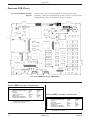
NOTE
The procedures in this manual reflect software version
6.
TRADEMARKS AND COPYRIGHT
Trademarked names appear throughout this document. Rather
than list the names and entities that own the trademarks or
insert a trademark symbol with each mention of the trademarked
name, the publisher states that it is using the names only for
editorial purposes and to the benefit of the trademark owner with
no intention of improperly using that trademark.
Registered trademarks
ACCUSKETCH, APEX, AQUA-KNOT, ARCHIVIST, BABY MAC,
CASE, CD TELEMETRY, CENTRA, CHART GUARD, CINE 35,
CORO, COROMETRICS, CRG PLUS, DIGISTORE, Digital DATAQ,
E for M, EAGLE, Event-Link, HELLIGE, IMAGE STORE, LASER
SXP, MAC, MAC-LAB, MACTRODE, MARQUETTE, MARQUETTE
UNITY NETWORK, MARS, MAX, MEI, MEI in the circle logo,
MEMOPORT C, MIDAS SYSTEM, MIDASNET, MINISTORE,
MINNOWS, Monarch 8000, MULTI-LINK, MULTISCRIPTOR,
MUSE, Neo-Trak, OXYMONITOR, PRESSURE-SCRIBE, PRES-RCUFF, QMI, QS, Quantitative Medicine, Quantitative Sentinel,
Qwik Connect Spiral, RAMS, SAM, SEER, SOLAR, Spectra 400,
Spectra-Tel, ST GUARD, TRAM, TRAM-NET, TRAM-RAC,
TRAMSCOPE, TRIM KNOB, UNITY NETWORK, UNITY twist logo,
Vari-X, Vari-X Cardiomatic, and VAS are trademarks of Marquette
Medical Systems, Inc. registered in the United States Patent and
Trademark Office.
Trademarks
12SL, 15SL, AccuVision, ADVANTAGE, AUTOSEQ, BODYTRODE,
CardioMail, CardioServ, CardioSmart, CardioSpeak, CardioSys,
CD TELEMETRY‚-LAN, CENTRALSCOPE, Corolation, Corometrics
Sensor Tip, CV Mail, CV-Web, DASH, EDIC, HI-RES, IMAGE
VAULT, INTELLIMOTION, INTER-LEAD, LIFEWATCH,
MARQUETTE MEDICAL SYSTEMS, MARQUETTE‚ RESPONDER,
MENTOR, MIDAS Com, MRT, MUSE CardioWindow, MUSE CV,
MUSEWord, O2SENSOR, OMRS, OnlineABG, Premium, RSVP,
SILVERTRACE, SMART-PAC, SMARTLOOK, SOLARVIEW,
Spectra-Overview, Trimline, UNITY, and Universal are trademarks
of Marquette Medical Systems, Inc.
Copyright
© 1997 Marquette Medical Systems, Inc. All rights reserved.
DOCUMENT DATE
12 MAY 1997
T-2
DOCUMENT PART NUMBER
407300-123
EAGLE 4000 PATIENT MONITOR
407300-123
REVISION E
GENERAL
HOW TO REACH US ...
TELEPHONE NUMBERS AND
ADDRESSES
ORDERING SUPPLY ITEMS
The following are telephone numbers and addresses for
contacting various Marquette Electronics Service and Supplies
Division departments.
Supply items are generally items used during normal operation
of a product. Leadwires, electrode paste, patient cables, and
printer paper are examples of supply items.
Make telephone inquiries about supply items at:
1-800-558-5102 (U.S. only),
1-407-575-5000 (outside the U.S.), or
1-407-575-5050 (fax).
Address orders or inquiries to:
Attn: Supplies Department
Marquette Electronics Service & Supplies Division
P.O. Box 9100
100 Marquette Drive
Jupiter, FL 33468-9100
ORDERING SERVICE PARTS
Service parts are items that are not expended in the normal
operation of the product. They are generally replacements for
defective or malfunctioning items inside the product. Service
parts include PCB assemblies, electronic components, internal
cables and harnesses, software or firmware, and operator and
service manuals. When ordering additional operator manuals,
remember to notate the software version from the start-up
screen.
A part number for the item to be replaced is necessary for
ordering a service part. If the part number for the desired item is
unobtainable, the following will be necessary to order the item:
SERVICE CALLS
•
model and serial number of the equipment,
•
part number/name of the assembly where the item is used,
•
item name, and
•
where applicable, reference designation (ex., R3, S1, U32).
To open a service call with Marquette Electronics Service
Department, contact Service Dispatch at:
1-800-558-7044 (U.S. only), or
1-407-575-5000 (outside the U.S.).
SERVICE MAINTENANCE
AGREEMENTS
For questions regarding service maintenance agreements,
contact the service and supplies division at:
1-800-552-3248, or
1-407-575-5000 ext. 4206.
REVISION E
EAGLE 4000 PATIENT MONITOR
407300-123
III
GENERAL
HOW TO REACH US ... (CONT)
Technical Support has the most current information about your
equipment and can provide assistance with any technical
questions or problems.
TECHNICAL SUPPORT
For All Hardware
For technical advice concerning any equipment in your
Marquette Electronics monitoring system, contact Tech
Support—Monitoring Hardware at:
1-800-558-7822, or
(407) 575-5000 ext. 4216.
Telemetry
For technical advice concerning your Telemetry system, contact
Tech Support—Telemetry at:
1-800-552-3243, or
(407) 575-5000 ext. 4202.
Series 7000/7010
For technical advice concerning Series 3000, 7000/7010 patient
monitoring equipment, contact Tech Support:
1-800-443-0980, or
(407) 575-5000 ext. 4217.
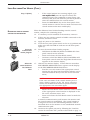
48-Hour Turnaround Repair
Some Marquette products (Input Modules, Tram modules, Series
7700 ECG Telemetry Transmitters, and CD Telemetry
Transmitters) are repaired on a 48-hour turnaround basis.
To inquire about status of 48-hour turnaround repair items, or if
you have questions before shipping an assembly to be repaired,
call:
1-800-552-3243, or
(407) 575-5000.
Service Address
Send items for 48-hour repair and all monitoring repair items to:
Attn: Monitoring Repair
Marquette Electronics Service and Supplies
P.O. Box 9100
100 Marquette Drive
Jupiter, FL 33468-9100
MAIN SWITCHBOARD
The main switchboard operator will direct your call to the person
most able to assist you. For any other questions or problems,
contact the main switchboard operator at:
1-800-558-5120, or
(407) 575-5000.
IV
EAGLE 4000 PATIENT MONITOR
407300-123
REVISION E
GENERAL
TABLE OF CONTENTS
GENERAL
Trademarks and Copyright .............................................. ii
How To Reach Us ... ............................................................ iii
Telephone numbers and addresses ................................. iii
Ordering supply items .................................................... iii
Ordering service parts .................................................... iii
Service calls ................................................................... iii
Service maintenance agreements .................................... iii
Technical Support .......................................................... iv
Main switchboard ........................................................... iv
SECTION 1
EQUIPMENT OVERVIEW
Product Description .......................................................... 1-2
About the monitor ....................................................... 1-2
Marquette Unity Network .................................................. 1-3
Monitor application ..................................................... 1-3
Patient monitoring system application ......................... 1-3
Hospital-wide network application ............................... 1-3
Front Panel Controls/Connectors ...................................... 1-4
Rear Panel Controls/Connectors ........................................ 1-5
About the remote alarm connector .............................. 1-6
Performance Specifications ............................................... 1-7
Preparation For Use ......................................................... 1-16
Power requirements .................................................. 1-16
Equipment ground requirements ............................... 1-16
Fuse and voltage setup .............................................. 1-17
Voltage selector card setup ........................................ 1-17
Monitor ventilation requirements .............................. 1-18
Mounting recommendations ...................................... 1-18
Software setup .......................................................... 1-18
Theory of Operation ........................................................ 1-19
Overall block diagram ............................................... 1-19
Overall block theory .................................................. 1-20
Power supply PCB block diagram .............................. 1-21
Power supply PCB block theory ................................. 1-22
Acquisition PCB block diagram .................................. 1-23
Acquisition PCB block theory .................................... 1-24
Processor PCB block diagram .................................... 1-25
Processor PCB block theory ....................................... 1-26
(Optional) EtCO2 PCB block diagram ........................ 1-27
(Optional) EtCO2 PCB block theory ........................... 1-28
SECTION 2
MAINTENANCE
Maintenance Schedule ....................................................... 2-2
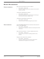
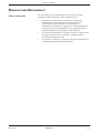
Manufacturer recommendation ................................... 2-2
Manufacturer responsibility ........................................ 2-2
Visual Inspection ............................................................... 2-3
Inspecting the monitor ................................................ 2-3
Cleaning The Monitor ........................................................ 2-4
Cleaning the display .................................................... 2-4
Cleaning the external surfaces .................................... 2-4
Manufacturer recommendation ................................... 2-4
REVISION E
EAGLE 4000 PATIENT MONITOR
407300-123
V
GENERAL
TABLE OF CONTENTS (CONT)
Section 2
Maintenance (Cont)
Checkout Procedures ......................................................... 2-5
About the checkout procedures ................................... 2-5
Manufacturer recommended test equipment................ 2-5
Power-up self-test ....................................................... 2-6
ECG tests .................................................................... 2-7
12SL ECG tests ........................................................... 2-9
Respiration tests ....................................................... 2-10
Temperature tests ..................................................... 2-11
Cardiac output tests .................................................. 2-12
Invasive blood pressure tests ..................................... 2-13
Pulse oximetry tests .................................................. 2-15
Non-invasive blood pressure tests ............................. 2-17
End-tidal carbon dioxide tests ................................... 2-22
Defib synch tests ....................................................... 2-24
Battery tests ............................................................. 2-26
Speaker tests ............................................................ 2-27
Checkout procedure completion ................................ 2-27
Electrical Safety Tests ..................................................... 2-28
Current leakage tests ................................................ 2-28
Wall receptacle tests .................................................. 2-29
Surface continuity tests ............................................ 2-29
Ground wire to ground tests ...................................... 2-30
Chassis to ground tests ............................................. 2-31
Patient source tests ................................................... 2-32
Patient sink tests ...................................................... 2-34
Test completion ......................................................... 2-35
Hi-Pot (Dielectric Withstand) Tests ............................ 2-36
SECTION 3
CALIBRATION
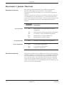
Adjustments / Jumpers / Switches ................................... 3-2
Hardware calibration ................................................... 3-2
Software calibration .................................................... 3-2
Processor PCB ................................................................... 3-3
About the procedure .................................................... 3-3
Test equipment ........................................................... 3-3
Calibration procedure ................................................. 3-3
Switch (SW1) settings - color display ........................... 3-4
Switch (SW1) settings - mono display .......................... 3-4
BP analog output null and gain calibration .................. 3-5
Low battery voltage threshold calibration .................... 3-6
Switch settings ............................................................ 3-7
Jumper setting ............................................................ 3-8
Acquisition PCB ................................................................ 3-9
About the procedure .................................................... 3-9
Test equipment ........................................................... 3-9
Calibration procedure ................................................. 3-9
Power Supply PCB ........................................................... 3-11
About the procedure .................................................. 3-11
Test equipment ......................................................... 3-11
Calibration procedure ............................................... 3-11
VI
EAGLE 4000 PATIENT MONITOR
407300-123
REVISION E
GENERAL
TABLE OF CONTENTS (CONT)
Section 3
Calibration (Cont)
Non-invasive Blood Pressure ............................................ 3-14
About the procedure .................................................. 3-14
Manufacturer recommendation ................................. 3-14
Test equipment ......................................................... 3-14
Calibration procedure ............................................... 3-15
End-tidal CO2 .................................................................. 3-22
About the procedure .................................................. 3-22
Test equipment ......................................................... 3-22
Pretest setup ............................................................. 3-22
Calibration procedure ............................................... 3-23
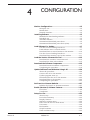
SECTION 4
CONFIGURATION
Monitor Configurations ..................................................... 4-2
Setup for use .............................................................. 4-2
Stand-alone ................................................................ 4-2
Network interface ........................................................ 4-2
Installing Software ............................................................ 4-3
Methods for downloading software ............................... 4-3
Intended use ............................................................... 4-4
Available software ....................................................... 4-4
Summarized download procedures .............................. 4-5
Summarized download procedures (Cont) .................... 4-6
Load Software For Update .................................................. 4-7
Use the Correct Loading Procedure .............................. 4-7
Load software onto a central station ............................ 4-7
Download from a central station to the monitor ......... 4-10
Use the Correct Loading Procedure ............................ 4-11
Download from memory card to the monitor .............. 4-11
Load the Version 6 Conversion Tool ................................. 4-12
Download the version 6 conversion tool ..................... 4-12
Download the boot code software .............................. 4-13
Download the Software Components ................................ 4-15
Download monitor software components ................... 4-15
Completing the procedure ......................................... 4-18
Update Software From Diskettes Using A PC .................... 4-20
About the procedure .................................................. 4-20
Connect the PC to the monitor .................................. 4-20
Update program start-up ........................................... 4-21
Download from the PC to the monitor ........................ 4-22
Download files to the monitor .................................... 4-23
Completing the procedure ......................................... 4-25
Set French or German Defaults ........................................ 4-27
Defaults for French or German monitors ................... 4-27
Enable (Version 6) Software Features ............................... 1-29
Procedure .................................................................. 1-29
Completion ............................................................... 1-31
REVISION E
EAGLE 4000 PATIENT MONITOR
407300-123
VII
GENERAL
TABLE OF CONTENTS (CONT)
Section 4
Configuration (Cont)
SECTION 5
TROUBLESHOOTING
Setup For Use .................................................................. 4-32
About setup .............................................................. 4-32
Procedure summary .................................................. 4-32
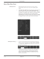
Display features ........................................................ 4-33
Software revision menu ............................................. 4-34
Enter into the service mode menu ............................. 4-35
Unit name ................................................................. 4-36
Bed number .............................................................. 4-38
Graph locations ......................................................... 4-40
Time and date setup ................................................. 4-43
Battery Failure .................................................................. 5-2
Battery replacement .................................................... 5-2
The BATT FAIL indicator ............................................. 5-2
Power Source Tests ........................................................... 5-4
Wall receptacle ............................................................ 5-4
Power cord and plug .................................................... 5-5
Main power and display power control ......................... 5-5
Data Acquisition Tests ....................................................... 5-6
ECG functional tests ................................................... 5-6
ECG test failure solutions ........................................... 5-7
Lead fail functional tests ............................................. 5-8
Lead fail test failure solutions ...................................... 5-8
Pacemaker pulse detection functional tests ................. 5-9
Pace detect test failure solutions ................................. 5-9
Invasive BP functional tests ....................................... 5-10
BP test failure solutions ............................................ 5-11
Respiration functional tests ....................................... 5-12
Respiration test failure solutions ............................... 5-13
NBP functional tests and test failure solutions .......... 5-14
Service Mode Menu ......................................................... 5-15
About the service mode menu ................................... 5-15
Access to the service mode menu .............................. 5-16
About service mode menu option items ..................... 5-17
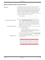
Review errors ............................................................ 5-18
More about review errors ........................................... 5-21
Error logs .................................................................. 5-22
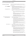
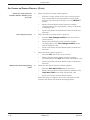
Service Tips .................................................................... 5-23
Fault/symptom analysis ........................................... 5-23
Acquisition PCB symptoms ........................................ 5-24
Processor PCB symptoms .......................................... 5-24
Power supply PCB symptoms and applications .......... 5-25
End-tidal CO2 messages ........................................... 5-26
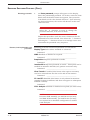
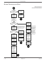
Network Troubleshooting ................................................ 5-27
VIII
EAGLE 4000 PATIENT MONITOR
407300-123
REVISION E
GENERAL
TABLE OF CONTENTS (CONT)
SECTION 6
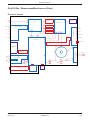
ASSEMBLY DRAWINGS
Assembly Drawings ............................................................ 6-2
About this section ....................................................... 6-2
About the assembly drawings ...................................... 6-2
Pn D412186e - Color ......................................................... 6-3
About the assembly drawings ...................................... 6-3
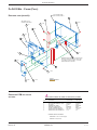
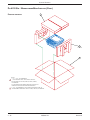
Packing materials ........................................................ 6-4
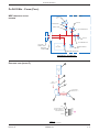
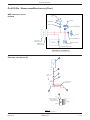
NBP pneumatic circuit diagram ................................... 6-5
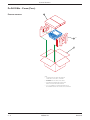
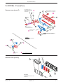
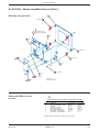
Exploded view (detail G) .............................................. 6-5
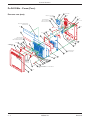
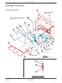
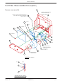
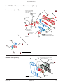
Exploded view (rear) .................................................... 6-6
Exploded view (detail B) ............................................... 6-7
Fuse replacement/voltage settings .............................. 6-8
Exploded view (detail C) ............................................... 6-9
Exploded view (detail F) ............................................... 6-9
Exploded view (front) ................................................. 6-10
Exploded view (detail A) ............................................. 6-11
Processor PCB dip switch settings ............................. 6-11
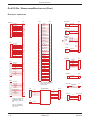
Electrical connectors ................................................. 6-12
Electrical diagram ..................................................... 6-13
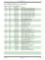
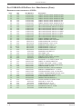
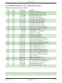
Pn. 412186-023e/-024e Parts List - Color ........................ 6-14
Pn 412185m - Monochrome/Non-Invasive ....................... 6-17
About the assembly drawings .................................... 6-17
Packing materials ...................................................... 6-18
NBP pneumatic circuit diagram ................................. 6-19
Exploded view (detail G) ............................................ 6-19
Exploded view (rear) .................................................. 6-20
Exploded view (detail B) ............................................. 6-21
Fuse replacement/voltage settings ............................ 6-22
Exploded view (detail C) ............................................. 6-23
Exploded view (detail F) ............................................. 6-23
Exploded view (front) ................................................. 6-24
Exploded view (detail A) ............................................. 6-25
Processor PCB dip switch settings ............................. 6-25
Electrical connectors ................................................. 6-26
Electrical diagram ..................................................... 6-27
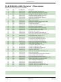
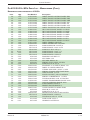
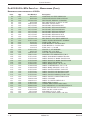
Pn 412185-021l/-022e Parts List - Monochrome .............. 6-28
Pn. 412185-012l/-023e Parts List - Non-Invasive ............. 6-31
SECTION 7
ABOUT THE MANUAL
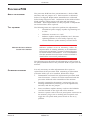
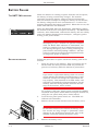
Field Service Manual ......................................................... 7-2
Intended use ............................................................... 7-2
Scope of the manual .................................................... 7-2
Manual content ........................................................... 7-2
Page Layout ....................................................................... 7-3
Related Documentation ..................................................... 7-4
Operator information .................................................. 7-4
Service information ..................................................... 7-4
Manufacturer Responsibility .............................................. 7-5
Liability disclaimer ...................................................... 7-5
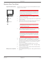
Notes, Cautions, and Warnings .......................................... 7-6
What these indicate ..................................................... 7-6
REVISION E
EAGLE 4000 PATIENT MONITOR
407300-123
IX
GENERAL
TABLE OF CONTENTS (CONT)
Section 7
About the Manual (Cont)
Parts Lists ......................................................................... 7-6
Dimension specifications ............................................. 7-6
Abbreviations .................................................................... 7-7
Page Changes .................................................................... 7-9
List of page changes .................................................... 7-9
X
EAGLE 4000 PATIENT MONITOR
407300-123
REVISION E
EQUIPMENT
OVERVIEW
1
Product Description .......................................................... 1-2
About the monitor ....................................................... 1-2
Marquette Unity Network .................................................. 1-3
Monitor application ..................................................... 1-3
Patient monitoring system application ......................... 1-3
Hospital-wide network application ............................... 1-3
Front Panel Controls/Connectors ...................................... 1-4
Rear Panel Controls/Connectors ........................................ 1-5
About the remote alarm connector .............................. 1-6
Performance Specifications ............................................... 1-7
Preparation For Use ......................................................... 1-16
Power requirements .................................................. 1-16
Equipment ground requirements ............................... 1-16
Fuse and voltage setup .............................................. 1-17
Voltage selector card setup ........................................ 1-17
Monitor ventilation requirements .............................. 1-18
Mounting recommendations ...................................... 1-18
Software setup .......................................................... 1-18
Theory of Operation ........................................................ 1-19
Overall block diagram ............................................... 1-19
Overall block theory .................................................. 1-20
Power supply PCB block diagram .............................. 1-21
Power supply PCB block theory ................................. 1-22
Acquisition PCB block diagram .................................. 1-23
Acquisition PCB block theory .................................... 1-24
Processor PCB block diagram .................................... 1-25
Processor PCB block theory ....................................... 1-26
(Optional) EtCO2 PCB block diagram ........................ 1-27
(Optional) EtCO2 PCB block theory ........................... 1-28
REVISION E
EAGLE 4000 PATIENT MONITOR
407300-123
1-1
EQUIPMENT OVERVIEW
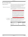
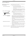
PRODUCT DESCRIPTION
The monitor is a compact, self-contained patient monitor
incorporating many advanced features previously found only in
complete modular systems.
ABOUT THE MONITOR
Compact design
Multi-lead ST and arrhythmia
monitoring
Measuring a compact 12.8 x 12.5 x 5.6 inches, and weighing just
under 18 pounds, the monitor is thin and unobtrusive enough
for locations previously considered impractical. The display is an
impressive 10.4 inches with exceptional visibility.
This full-featured vital signs monitor offers various software and
hardware options which allow it to be configured to meet the
needs of specific care
units. The basic
monitor includes multilead ECG, respiration,
two temperatures (or
cardiac output), two
invasive blood pressures
and pulse oximetry.
The monitor meets the
needs of a variety of
care areas from
subacute to acute
incorporating additional
monitoring features
such as: simultaneous
multi-lead arrhythmia
analysis, multi-lead
arrhythmia event recall,
enhanced multi-lead ST
segment measurement
capabilities,
thermodilution cardiac
output determination with cardiac indices calculation,
pulmonary and dosage calculations, non-invasive blood
pressure, end-tidal carbon dioxide and more.
1-2
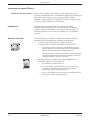
Network compatible
The monitor can be part of a patient monitoring network, an
open architecture, systems integration platform designed to
improve the efficiency and effectiveness of health care delivery,
permitting viewing of remote bed information and much more.
Easy to use
From software designed for specific care areas to the monitor's
unique Trim Knob® control, the monitor was designed to be as
easy to use as it is comprehensive. The Mentor™ user support
system provides on-screen prompts and instructions as well as
answers to operational questions to assist novice users.
EAGLE 4000 PATIENT MONITOR
407300-123
REVISION E
EQUIPMENT OVERVIEW
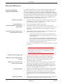
MARQUETTE UNITY NETWORK
MONITOR APPLICATION
The Marquette Unity Network (hereafter referred to as the
network) provides a method for standardized communication
with various Marquette medical systems devices. This versatile
monitor can operate both as a fully functional stand-alone device
and as a component on the network, depending upon the
application.
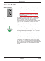
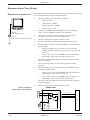
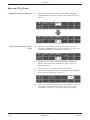
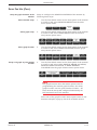
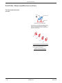
PATIENT MONITORING SYSTEM
When connected to the network, the monitor provides access to
other devices for many purposes. Marquette patient monitoring
equipment such as Centralscope central station monitor; Series
7200/7260 direct digital writer; CDT-LAN patient telemetry
system; ADU/Pager-LAN; and, Solar or other Eagle patient
monitors are examples of devices that can be used in conjunction
with the monitor when connected to the network.
APPLICATION
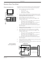
HOSPITAL-WIDE NETWORK
APPLICATION
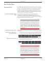
There are various types of information management and data
base systems devices which may also be integrated with the
monitor via connection to the network. Marquette medical
systems equipment such as MUSE cardiology management
system; MARS UNITY workstation; MARS 24 clinical review
station; MRT II automated vital sign and arrhythmia data
collection system; MAC-Lab cardiac catheterization system; QMI
patient data management system; and, MUSE HIS interface are
examples of systems and data bases which can be integrated
with the monitor on the network.
Patient monitoring system
application
TR
AM
SC
OP
E
12
TM
MA
RQ
UET
TE
tte
que
mar
P
GRAPH
GO/STO
!
E
SILENC
ALARM
KNOB
NBP
TRIM
ALL
ZERO
NBP
SYNC
DEFIB.
P
GO/STO SAO
2
BATT
FAIL
BP
AC
CHRGNG
BP
PWR
Y
DISPLA
ON/OFF
RDY
O
BAT
TEMP/C
ISOLATED
ECG
TR
AM
SC
OP
MA
E
RQ
12
UET
TE
tte
que
mar
P
GRAPH
GO/STO
!
E
SILENC
ALARM
NBP
KNOB
TRIM
ALL
ZERO
NBP
SYNC
DEFIB.
P
GO/STO SAO
2
BATT
FAIL
BP
AC
CHRGNG
BP
PWR
Y
DISPLA
ON/OFF
RDY
O
BAT
TEMP/C
ISOLATED
ECG
CD
T
OP SYST
ER
AT EM
IO
NA
L
ma
rqu
ette
CD
TEL
EM
ETR
Y
REVISION E
EAGLE 4000 PATIENT MONITOR
407300-123
1-3
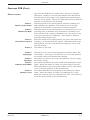
EQUIPMENT OVERVIEW
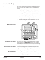
FRONT PANEL CONTROLS/CONNECTORS
NOTE
To insure patient safety, use only parts and accessories manufactured or recommended
by the manufacturer. Parts and accessories used must meet the requirements of the
applicable IEC 601 series safety standards, and/or the system configuration must meet
the requirements of the IEC 601-1-1 medical electrical systems standard.
Display: Two types are available:
Monochrome —
Hi-bright electroluminescent (EL) display panel.
Color —
Active matrix thin film transistor (TFT) LCD panel.
Screen size —
10.4-inch diagonal
Resolution —
640 x 480 pixels
Front Panel Controls: Five backlit
pushbutton operator controls provide
the following functions:
DISPLAY
ON/OFF
NBP
GO/STOP
70
5
ED
U-B
SIC
GED
AR
CH
200
80
S
P
OB
mm
60
10
D
P
B
RO
R
ITO
T
GH )
HLI reen
TH
HIG of sc ).
ING
to
ob side en
RAT
Kn ht of scre
OPE
rig
Trim ar m
the ls (f otto
er
TE labe ns (b
TA
met tions
RO meter optio
para u op
u
ra
en
CT
e yed.
pa men
LE m
SE ed g th la
and
to Relat ribin is disp
ob
Kn ns. desc n
im tio line optio
e Tr u op ge enu
enu.
S th en sa m
nm
ES d m mes ed
u.
mai
PR ls an . A light
to
ar gh
men
rn
labeappe a hi
us
io
of
retu
y an
will tion
prev
spla
ct to
lay
func
ill di
Sele
disp
uw
IN
MA
ct to
men
NU
ME
Sele
pup
S
SE
IOU
a po
EV
CLO OW
PR NU
D
from.
ME
P
EL w
WIN
g H indo
ctin ion w
le
Se rmat
info
ON
T
NEXOW
D
Y
PLA
DIS ONS
TI
OP
H&
AP
GR RMS
ALA
42
30
C
O
30
5
R
R
32
160
1
AR
20
0
60
2
SILENCE
ALARM
Sets zero references for
all invasive blood
pressure functions.
Controls patient alarm
silencing functions.
PA
0
II
GRAPH
GO/STOP
II
RR
T:
TIEN ED
PA ARG
H
ISC
E
MIZ
STO R
CU NITO
MO
S&
LC S
CA RIE
TO
HIS
WIN
C
.4°
V
Manually starts or stops
the noninvasive blood
pressure function.
P
A
2
Hg
mm
ZE
EM
ZERO ALL
A
R
1
Hg
ZER
DIS
II
N
RTI
MA
E
150 C
50 G
When operating on ac
power, controls only
display power. When
operating on battery
power, controls overall
monitor power.
D
H
APOP
GR/ST
GO
CE
EN M
SILLAR
A
BP
N
RO
Manually starts or stops
graphs to selected
writers. Manually stops
alarm graphs.
!
OB
IM
KN
TR
ALL
NC
ZE
. SY
IB
TT
BA
P P
NB TO
O2
O/S
G
DEF
SA
IL
FA
BP
NG
RG
AC
R
CH
Y
RD
PW
BP
Trim Knob Control: This is the
control that is used most often to
choose menu items and enter
data.
T
Y
PLA
FF
/O
DIS
ON
BA
CO
P/
M
TE
ED
LAT
ISO
G
EC
Patient Input
Connectors: Used to
attach patient cables
for various
electrodes, sensors
and transducers used
in patient signal
acquisition
Rotate the Trim Knob
control to highlight an
item on the display.
Press the Trim Knob
control to select the
highlighted item.
Indicators: Five LED's indicate the following power
related conditions of the monitor:
PWR-AC: Monitor is
operating on ac power
BATT-RDY: The
battery is fully
charged — monitor
is ready for battery
powered use
PWR-BATT: Monitor is
operating on battery
power
PWR
AC
BATT
RDY
BATT-CHRGNG: The battery is
charging — the monitor is not
ready for battery powered use
1-4
BATT
CHRGNG
FAIL
BATT-FAIL:
The battery
has failed and
requires
maintenance
NBP Connector: A pneumatic connector for
attaching a noninvasive blood pressure cuff
to the monitor.
DEFIB SYNC: This front panel jack provides a direct
interface between the monitor and a defibrillator for
synchonization of the two devices during emergency
defibrillation or for synchronized cardioversion. The
signals available through this connector are:
Outputs —
•
Defib sync pulse
•
Analog ECG signal
•
Analog invasive BP signal
Input —
•
Defibrillator triggered marker pulse
EAGLE 4000 PATIENT MONITOR
407300-123
REVISION E
EQUIPMENT OVERVIEW
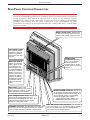
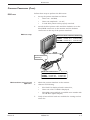
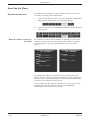
REAR PANEL CONTROLS/CONNECTORS
NOTE
The use of ACCESSORY equipment not complying with the equivalent safety requirements
of this equipment may lead to a reduced level of safety of the resulting system.
Consideration relating to the choice shall include: use of the accessory in the PATIENT
VICINITY; and evidence that the safety certification of the ACCESSORY has been
performed in accordance to the appropriate IEC 601-1 and/or IEC 601-1-1 harmonized
national standard.
Battery Access Cover: Remove two
screws to access the optional Ni-Cad
battery pack located under this cover.
Serial Number Label:
Describes the type of
equipment, date and
sequence of product
manufacture for each
monitor.
MO
DE
L NO
.
MAR
QUE
TT
E EL
EC
SE
TR
ONI
CS
RIAL
INC.
NO
.
MIL
WAU
W
CA
A
KE
UT
EW
RE RN
IO
PL IN
I. US
N
AC G:
A 70
E
PO
20
6-00
W FUS
4
E(S RIS
ER
)A KO
S
F
M FIR
V
AR E
KE
10
0V
D
I
12
0V
22
0V
24
0V
50-60 Hz
Main Power Switch:
Selects ac or battery
power. When in the
on (I) position, the
monitor operates on
ac power and battery
charging is enabled.
When in the off (0)
position, the monitor
operates on battery
power controlled by
the DISPLAY ON/OFF
pushbutton switch
located on the front
panel.
ASYNC COMM
Connectors (2): These
ports can be used for
interconnection to
remote controls, direct
digital writers and other
devices
ET
H
NEERT
RM
VIDT
AS
YN
C
RM CO
T A MM
LR
M ASY
NC
RM CO
T A MM
LR
M
Main Power: A power cord
connected between this port and a
wall receptacle is used for ac main
power operation of the monitor.
REMOTE ALARM Connector: This 9-pin
"D" connector provides interconnection to
the Marquette/Hellige Isolation Relay for a
nurse-call light system. The following
alarms will trigger these outputs:
•
CRISIS Patient Status Alarms, and
•
WARNING System Status Alarms.
Fuse/Voltage Selector Cover: Main power
fuses and the voltage selector for the
monitor are located behind this cover. The
label above the cover shows the correct
ratings for replacement fuses.
ETHERNET Connector: An IEEE 802.3 AUI cable and
transceiver can be connected to this port for monitors
used in patient monitoring network configurations.
REVISION E
RMT VID (remote video) Connector: For monitors
with color displays only, an external display monitor
can be connected to this port for viewing patient
information from a remote location.
EAGLE 4000 PATIENT MONITOR
407300-123
1-5
EQUIPMENT OVERVIEW
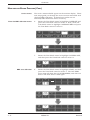
REAR PANEL CONTROLS/CONNECTORS (CONT)
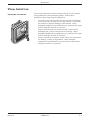
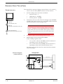
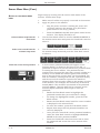
ABOUT THE REMOTE ALARM
CONNECTOR
How the system works
The remote alarm connector (REMOTE ALARM) is for use with
the Marquette/Hellige Isolation Relay, pn 303 444 77 (non-U.S.)
and pn 303 445 50 (U.S.). This accessory provides a relay
closure when either of the following alarms occur:
•
CRISIS (Patient Status Alarm), and/or
•
WARNING (System Status Alarm).
The signals from the REMOTE ALARM connector activate and
deactivate the isolation relay. When the monitor is initially
powered up or rebooted, the relay remains deactivated until the
monitor completes its power-up or reboot sequence. Once the
monitor successfully completes this sequence, the relay is then
activated.
If either of the above listed alarms occurs, the relay is
deactivated by the monitor. This causes the nurse call system to
notify personnel that an alarm situation exists at the monitor.
When the alarm has been cleared, the relay is activated. This
causes the nurse call system to notify personnel the alarm
situation has been cleared.
The relay is deactivated when AC power is removed from the
monitor.
1-6
EAGLE 4000 PATIENT MONITOR
407300-123
REVISION E
EQUIPMENT OVERVIEW
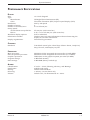
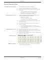
PERFORMANCE SPECIFICATIONS
DISPLAY
Size:
Type:
Monochrome:
Color:
Resolution:
Number of traces:
Number of seconds/trace:
Sweep speed:
All waveforms except EtCO2:
EtCO2:
Waveform display options:
Information window:
Display organization:
10.4-inch diagonal
Hi-Bright Electroluminescent (EL)
Thin-Film Transistor (TFT) Liquid Crystal Display (LCD)
640 by 480 pixels
6
6.0 at 25 mm/sec
25 mm/sec (with erase bar)
6.25, 12.5 or 25 mm/sec (with erase bar)
Full or individual
Displays non-real-time information without obstructing the
display of real-time information
Prioritized by parameter
CONTROLS
Standard:
Trim Knob control plus 4 hard keys: Silence Alarm, Graph Go/
Stop, Zero All, and Display On/Off
PROCESSING
Main processor:
Data acquisition processor:
Graphics processor:
Program storage:
Data storage:
MC68332 32-bit integrated microcontroller (19.968 MHz)
MC68332 32-bit integrated microcontroller (15.72 MHz)
TMS34010 32-bit graphics system processor (50 MHz)
4-MB flash memory
2-MB RAM (battery backed-up)
ALARMS
Classification:
Notification:
Setting:
Silencing:
Volume:
REVISION E
4 levels — Crisis, Warning, Advisory, and Message
Audible and visual
Default and individual
1 minute, current alarm only
Default 70%, 70 dB measured at 1 meter
EAGLE 4000 PATIENT MONITOR
407300-123
1-7
EQUIPMENT OVERVIEW
PERFORMANCE SPECIFICATIONS (CONT)
ECG
Standard leads available:
(Optional) 12SL leads available:
Leads analyzed simultaneously:
Lead fail:
Alarms:
Input specifications:
Voltage range:
Signal width:
Heart rate range:
Input impedance:
Common mode:
Differential:
Output specifications:
Frequency response:
Display:
Diagnostic:
Monitoring:
Moderate:
Maximum:
DDW:
Diagnostic:
Monitoring:
Moderate:
Maximum:
Common mode rejection:
Gain:
Linearity deviation:
Noise:
Pacemaker detection/rejection:
Input voltage range:
Input pulse width:
Rise time:
Over/under shoot:
Baseline drift:
I, II, III, V, aVR, aVL, and aVF
V2, V3, V4, V5 and V6
I, II, III, and V (multi-lead mode)
Identifies failed lead
User selectable upper and lower heart rate limits
±0.5 mV to ±5 mV
40 ms to 120 ms (Q to S)
30 to 300 BPM
>10 MΩ at 50/60 Hz
>2.5 MΩ from dc to 60 Hz
0.05 to
0.05 to
0.05 to
5 to 25
120 Hz
40 Hz
25 Hz
Hz
0.05 to 120 Hz
0.05 to 40 Hz
0.05 to 25 Hz
0.05 to 25 Hz
90 dB minimum at 50 Hz or 60 Hz
1000 ±3%
±3%
<30 µ V RTI (referred to input)
±2 mV to ±700 mV
0.1 ms to 2 ms
10 µ s to 100 µ s
2 mV (max)
<0.5 mV/hour with a ±700-mV, 2-ms pacemaker pulse applied
RESPIRATION
Measurement technique:
Impedance variation detection
Range:
Respiration rate:
1 - 200 breaths per minute
Base impedance:
100 - 1000 Ω at 52.6 kHz excitation frequency
Detection sensitivity:
0.4 to 10 Ω variation
Waveform display bandwidth:
0.1 to 1.8 Hz (–3 dB)
Alarms:
User-selectable upper and lower respiration rate limits, and user-selectable apnea limit
1-8
EAGLE 4000 PATIENT MONITOR
407300-123
REVISION E
EQUIPMENT OVERVIEW
PERFORMANCE SPECIFICATIONS (CONT)
TEMPERATURE (TEMP)
Number of channels:
2
Input specifications:
Probe type:
Temperature range:
Resolution:
YSI Series 400 or 700 thermistor (determined by input cable)
0°C to 45°C (32°F to 113°F)
±0.1°C
Output specifications:
Parameters displayed:
Gain:
Linearity:
dc drift:
Error:
Noise:
Alarms:
T1, T2
121.95 ±1%
<1% from 30°C to 42°C
<1 mV/°C
(independent of source) ±0.1°C for YSI series 400 probes; ±0.3°C
for YSI series 700 probes
<20 mV from dc to 100 Hz
User-selectable upper and lower limits for T1, T2
CARDIAC OUTPUT (CO)
Availability:
Input specifications:
Probe type:
Catheter size:
Injectate volume:
Output specifications:
Parameters displayed:
Included in 7020, 7025, and 7030 software packages. Not
available in 7015 software package.
In-line or bath probe
5F, 6F, 7F, 7.5F, and 8F
3, 5, or 10 cc
Cardiac output, blood temperature, injectate temperature, trial
number
Range:
Cardiac output:
0.2 - 15 liters per minute
Blood temperature:
30 - 42°C
Injectate temperature:
0 - 30°C
Noise: <20 mV from dc to 100 Hz
Accuracy:
Cardiac output:
Blood temperature:
Injectate temperature:
Frequency response:
Noise:
REVISION E
±5% (liters of blood/min)
±0.2°C
±0.3°C
dc to 15 Hz ±2 Hz
<20 mV from dc to 100 Hz
EAGLE 4000 PATIENT MONITOR
407300-123
1-9
EQUIPMENT OVERVIEW
PERFORMANCE SPECIFICATIONS (CONT)
INVASIVE BLOOD PRESSURE (BP)
Number of channels:
Transducer sites:
Transducer requirements:
Excitation voltage:
Transducer output:
Input specifications:
Range:
Offset:
Input impedance:
Common mode:
Differential:
Output specifications:
Gain:
Frequency response:
Gain stability:
Zero balance range:
Zero balance accuracy:
Zero balance drift:
Common mode rejection:
Noise:
Accuracy:
Alarms:
2
Arterial (ART), femoral artery (FEM), pulmonary artery (PA),
central venous (CVP), right atrial (RA), left atrial (LA), intracranial
(ICP), and special (SP)
±2.5 Vdc ±0.1%
50 µ V/V/cm Hg
–25 mmHg to 300 mmHg
±150 mmHg
>100 kΩ at 50/60 Hz
>100 kΩ from dc to 60 Hz
976 ±1%
dc to 50 Hz (+0/-3 dB)
< ±0.1%/°C, and < ±0.1% over any 24 hour period
±150 mmHg
±1 mmHg
±1 mmHg over 24 hours
>60 dB at 60 Hz
<5 mVp-p from dc to 30 Hz
±2% or ±1 mmHg, whichever is greater (exclusive of transducer)
User-selectable upper and lower limits for systolic, diastolic, and
mean pressures
PULSE OXIMETRY (SPO2)
Parameters monitored:
SpO2 range:
PPR range:
Accuracy
SpO2:
PPR
Alarms:
1 - 10
Arterial oxygen saturation (SpO2) and peripheral pulse rate (PPR)
50 - 100%
20 - 250 beats per minute (±3 beats per minute)
Actual accuracy depends on probe. Please reference
manufacturer’s specifications.
± 2% (70 - 100% SpO2) ±1 standard deviation
± 3% (50 - 69% SpO2) ±1 standard deviation
± 3 beats per minute
User-selectable upper and lower limits for SpO2 and PPR
EAGLE 4000 PATIENT MONITOR
407300-123
REVISION E
EQUIPMENT OVERVIEW
PERFORMANCE SPECIFICATIONS (CONT)
NON-INVASIVE BLOOD PRESSURE (NBP)
Measurement technique:
Displayed parameters:
Measurement modes:
Heart rate detection:
Total cycle time:
Automatic cycle times:
Auto zero:
Tubing length:
Adult:
Neonatal:
Automatic cuff deflation:
Cuff sizes:
Disposable:
Reusable:
Alarms:
REVISION E
Oscillometric
Systolic, diastolic, and mean pressures, pulse rate, time of last
measurement
Manual, auto, and stat
30 to 300 beats per minute
20 to 40 seconds typical (dependent on heart rate and motion
artifact)
0 to 24 hours
Zero pressure reference prior to each cuff inflation
12 feet
8 feet
Cycle time exceeding 3 minutes (90 seconds neonatal), power off,
or cuff pressure exceeds 300 mmHg (+10%) adult, 150 mmHg
(+10%) neonatal
Large adult, adult, small adult, pediatric, small pediatric, and
infant
Thigh, large adult, adult, child, and infant
User-selectable upper and lower limits for systolic, diastolic, and
mean pressures
EAGLE 4000 PATIENT MONITOR
407300-123
1 - 11
EQUIPMENT OVERVIEW
PERFORMANCE SPECIFICATIONS (CONT)
END-TIDAL CARBON DIOXIDE (ETCO2)
Information displayed:
Measurement technique:
Sensor type:
Patient interface:
Inspired and expired carbon dioxide measurement, respiration
rate measurement.
Non-dispersive infrared absorption, dual wavelength ratiometric.
Novametrix Medical Systems’ Capnostat III
Compatible with Novametrix Medical Systems’ Capnogard monitoring product.
Airway adaptor specifications:
Airway adaptor types:
Adult reusable (standard), adult disposable, neonatal
Airway adaptor dead space/chamber volumes:
Adult reusable:
<5 cc
Adult disposable:
<5 cc
Neonatal:
<0.5 cc
CO2 measurement specifications:
Measurement range:
Pi CO2/Fi CO2:
Pe CO2/Fe CO2:
RR:
Accuracy:
Display update interval:
CO2 averaging:
CO2 measurement stability:
Resolution:
Noise:
Repeatability:
Step response time:
Mainstream adult:
Mainstream neonate
Interference:
N2O gas:
O2 gas:
Barometric pressure:
Water vapor:
Anesthetic agent:
Airway adaptor variability:
Warm-up time:
Calibration:
Factory settings:
Verification:
CO2 sweep speed:
1 - 12
0 to 100 Torr/0 to 13%
0 to 100 Torr/0 to 13%
0 to 120 breaths/min
±2 mmHg or 5%, whichever is greater.
2 sec
Selectable from single breath, 10 seconds, or 20 seconds.
Accuracy maintained over 8 hours.
1 mmHg
0.5 mmHg or 2% (maximum), whichever is greater, measured
over a 10 second period.
±1 mmHg or ±2.5% (maximum), whichever is greater.
<60 ms (10-90%)
<50 ms (10-90%)
±2 mmHg or ±5% (maximum), whichever is greater, with N2O
compensation enabled.
±2 mmHg or ±5% (maximum), whichever is greater, with O2
compensation enabled.
±2 mmHg (maximum) from 500 to 800 mmHg, with barometric
pressure compensation enabled.
±0.5 mmHg or 1.5% (maximum), whichever is greater.
±0.5 mmHg (maximum) for concentration of no more than 5% of
halogenated agents.
±1.5 mmHg or 3% (maximum), whichever is greater, with same or
different adaptor; not applicable after adaptor zero.
Less than 15 seconds to initial CO2 indication, full specification
within 120 seconds; waveform immediate upon power up.
Factory calibration settings stored in nonvolatile memory within
the sensor; 15 second adaptor calibration when switching airway
types.
Zero and span performance check with on-cable verifier.
Selectable 6.25, 12.5, or 25 mm/sec
EAGLE 4000 PATIENT MONITOR
407300-123
REVISION E
EQUIPMENT OVERVIEW
PERFORMANCE SPECIFICATIONS (CONT)
Respiration rate specifications:
Range (for 5% step size):
Accuracy:
Resolution:
0-120 breaths per minute
±1 breath per minute
±1 breath per minute
Barometric pressure sensor specifications:
Range:
530-785 mmHg
Accuracy:
±7 mmHg
Calibration:
Calibrated at factory; user calibration in service menu.
Capnostat III sensor specifications:
Operating temperature:
Storage temperature:
Humidity:
Barometric pressure:
Shock resistance:
Moisture resistance:
10° to 40° C (50° to 104° F)
-30° to 65° C (-22° to 149° F)
5 to 95%, relative humidity, non-condensing.
500 to 800 mmHg
Able to withstand 6 ft. drop to tile floor.
Splash resistant sealed transducer
Cleaning and sterilization:
Sensor:
Transducer, cable and verifier may be wiped with cold chemical
disinfectant; no steam sterilization or EtO gas permitted; fluid
immersion not recommended.
Adult reusable airway adaptor: Disinfect with buffered glutaraldehyde, EtO gas, isopropyl alcohol, household bleach; also steam sterilizable and pasteurizable.
ESD susceptibility:
60 Hz interference:
Alarms:
REVISION E
No damage to the sensor from electrostatic discharge of 0.01 J at
up to 15 kV, applied to sensor connector pins.
<0.5 mmHg at 38 mmHg
Selectable upper and lower limits for CO2 and RR.
EAGLE 4000 PATIENT MONITOR
407300-123
1 - 13
EQUIPMENT OVERVIEW
PERFORMANCE SPECIFICATIONS (CONT)
ANALOG OUTPUT
ECG:
Gain:
DC offset:
Noise:
Frequency response:
Blood pressure:
Gain:
DC offset:
Noise:
Frequency response:
1 V/mV ±10%
±100 mV (max)
<5 mVp-p (0-300 Hz)
0.05 Hz to 100 Hz +7/–0 Hz
10 mV/mmHg ±2%
±20 mV (max)
<5 mVp-p (0-300 Hz)
dc to 50 Hz +2/–0 Hz
DEFIBRILLATOR SYNCHRONIZATION PULSE
Marker out:
Time delay:
35 ms (maximum), R-wave peak to leading edge of pulse.
Amplitude (selectable via internal DIP switch):
+5 V selection:
3.5 V (min) at 1 mA sourcing; 0.5 V (max) at 5 mA sinking.
+12 V selection:
11.0 V (min) at 1 mA sourcing; 0.75 V (max) at 5 mA sinking.
Pulse width:
10 ms ±10% or 100 ms ±10% in service menu (selectable via
internal DIP switch).
Output impedance:
50 Ω nominal
Current limit:
15 mA nominal, both sourcing and sinking.
Marker in:
Input threshold:
Input hysteresis:
Maximum input voltage:
Input impedance:
Pulse width:
1 - 14
VIH = ±2.5 V (min); VIL - ±1.5 V (max)
650 mV typical
±30 V (with respect to ground on pin 2)
10 kΩ (min) for -25 V < Vin < 25 V
1.0 ms (min), Vin > 2.5 V
EAGLE 4000 PATIENT MONITOR
407300-123
REVISION E
EQUIPMENT OVERVIEW
PERFORMANCE SPECIFICATIONS (CONT)
ENVIRONMENTAL SPECIFICATIONS
Power requirements:
AC voltage selections:
100 Vac ±10%
120 Vac ±10%
220 - 230 Vac ±10%
240 Vac ±10%
Power consumption:
Cooling:
Heat dissipation:
Battery:
Fuses:
100 Vac:
120 Vac:
220 – 230 Vac:
240 Vac:
Design (general):
Battery operation time:
General:
Monochrome EL display:
TFT Color LCD display:
Operating conditions:
Ambient temperature:
Relative humidity:
Storage conditions:
Maximum:
Minimum:
1.5 A
1.4 A
800 mA
700 mA
<50 watts
Convection
240 BTu/hr
Optional, nickel-cadmium (Ni-Cad), 12V, 1.8 ampere hour
T2.5A, 250 VAC, 5 x 20 mm
2.5 A, SB, 250 VAC
T1.25A, 250 VAC, 5 x 20 mm
T1.25A, 250 VAC, 5 x 20 mm
Continuous, not protected against ingress of liquids
Battery age will affect operating time. Not recommended for
transport. Serves as backup power source in the event of shortterm power loss. SpO2, EtCO2 and NBP monitoring, as well as
battery age, reduce operating time.
Typical operation time while monitoring ECG is 45 to 55 minutes
from a new, fully-charged battery.
Typical operation time while monitoring ECG is 15 to 30 minutes
from a new, fully-charged battery.
10 to 35°C (50 to 95°F)
30 - 70%
50°C (122°F) at 50% relative humidity, or
70°C (158°F) at 15% relative humidity
–25°C (–13°F)
PHYSICAL SPECIFICATIONS
Height:
32.6 cm (12.8 inches)
Width:
32 cm (12.5 inches)
Depth:
14.1 cm (5.6 inches)
Weight (optional battery pack installed):
With color display:
17.9 lb
With monochrome display:
17.5 lb
CERTIFICATION
UL:
IEC:
UL 2601-1 Listed.
C22.2 No. 601.1-M90
IEC 601-1 Certified.
WARRANTY
Standard:
Optional:
REVISION E
One year
Other options are available. Contact the manufacturer sales
representative for more information.
EAGLE 4000 PATIENT MONITOR
407300-123
1 - 15
EQUIPMENT OVERVIEW
PREPARATION FOR USE
POWER REQUIREMENTS
At least one grounded duplex wall receptacle should be provided
for each monitor. The wall receptacle should be hospital grade
and installed in a suitable junction box. Power should be
provided by a power line dedicated solely to equipment requiring
emergency power.
WARNING
Loss of power to the monitor results in the loss of all
monitoring functions.
EQUIPMENT GROUND
REQUIREMENTS
The ground pin of the wall receptacles and all exposed metal
parts (beds, radiators, water pipes, etc.) in the patient area
should be connected together and tied to the nearest
equipotential ground point through a bonded grounding system,
or with a 10-AWG stranded copper grounding cable. This
equipotential ground point should be as close to earth ground as
possible. Use only three-prong, polarized, hospital-grade wall
receptacles to accept the three-wire, polarized plug on the power
cord of the monitor.
If a bonded grounding unit is not available, interconnect the
ground pins of all wall receptacles in the patient and monitor
areas with 10-AWG (or larger) stranded copper cables. This
copper cable must connect to the central grounding point. Do
not jumper from ground pin to ground pin, then to the central
grounding point. The ground cabling must not carry current,
such as a grounded neutral, since the current flow will produce
differences in potential along the ground. These potential
differences are the main source for shock hazards to the users
and patients.
Do not rely on conduit as a ground conductor. Plastic (PVC)
pipes or fittings used as conduit break up the ground path,
which can present potential shock hazards. The electrical
ground system must be connected to actual earth ground. If this
is not possible, then a good reference ground such as a metal
cold water pipe or an electrically conductive building component
should be used. It is more important that all grounded objects in
the patient area are at the same potential than at true earth
potential.
1 - 16
EAGLE 4000 PATIENT MONITOR
407300-123
REVISION E
EQUIPMENT OVERVIEW
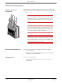
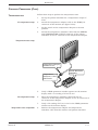
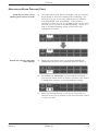
PREPARATION FOR USE (CONT)
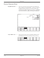
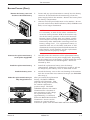
FUSE AND VOLTAGE SETUP
USE ONLY WITH 100V
120V
250V FUSES
I
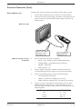
O
220V
240V
Fuse holder removal
To change the fuse arrangement and operating voltage setup of
the monitor, the settings on the power input module (located on
the rear panel of the monitor) must be configured properly.
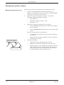
First, change the fuse arrangement. Follow these steps:
1.
Using a flat blade screwdriver, remove the fuse holder from
the power input module.
2.
Remove the fuse block from the fuse holder by loosening
the Phillips-head screw 2 full turns counterclockwise.
3.
Separate the fuse block from the fuse
holder by tilting it up and away from the
mount.
4.
Arrange fuses as required for proper
monitor operating voltage.
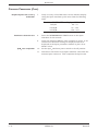
NOTE
Two fuses are required for 230/240 Vac operation. A
dummy fuse may be used in the neutral (lower)
holder. Fuse(s) inserted into the power input module
first, are the active set.
100/120 Vac setup
5.
To change fuse arrangement, invert the fuse holder and
reassemble it to the fuse block in the reverse order of steps
2 and 3.
230/240 Vac setup
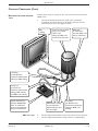
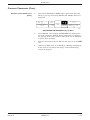
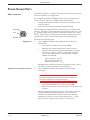
VOLTAGE SELECTOR CARD SETUP
Next, change the voltage selector for the correct operating voltage
of the monitor. Continue with these steps:
1.
With the fuse holder remaining out of the power input
module, remove the voltage selector card from the power
input module as well by pulling it straight out.
2.
Holding the indicator pin in the upright position, rotate the
selector card so the desired voltage is readable at the
bottom.
3.
Insert the voltage selector card into the power input module
such that the voltage lettering imprinted on the card is
facing the power on/off switch.
4.
Replace the fuse holder into the power input module and
verify the desired voltage is indicated, when viewed from the
rear panel.
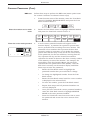
240
220
100
120
I
O
USE ONLY WITH 100V
120V
250V FUSES
220V
240V
Selected voltage
REVISION E
EAGLE 4000 PATIENT MONITOR
407300-123
1 - 17
EQUIPMENT OVERVIEW
PREPARATION FOR USE (CONT)
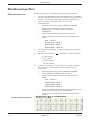
MONITOR VENTILATION
REQUIREMENTS
The monitor is capable of producing as much as 170 BTu per
hour of heat load. This is equivalent to approximately 50 watts
of energy.
WARNING
Failure to properly ventilate the monitor may cause
equipment failure or improper monitoring conditions which may endanger the patient being monitored.
MO
DEL
NO.
MA
RQU
ETT
E ELE
SER
CTR
IAL
ONI
NO.
CS
INC
. MIL
WA
W
CA
UKE
AR
UT
E WI.
RE NI
ION
NG
AC :
E
FU
ER SE(S) RIS
AS K OF
MA
PL
PO
CAUTION
Do not locate the monitor in an enclosed area that
may restrict the heat dissipated by it. Any restriction
in air flow causes a rise in internal temperature
which may result in equipment failure.
USA
702
06-0
04
FIR
RK E
ED
50-60 Hz
W
V
100
120V
220V
240V
V
I
ET
HE
NE
RT
RM
VIDT
AS
YN
C
RM CO
T AL MM
RM AS
YN
C
RM CO
T AL MM
RM
CAUTION
The monitor must be located no closer than 4 inches
(10 cm) from any partition or wall. The monitor can
be no closer than 12 inches (30 cm) from any
overhead partition or the ceiling.
MOUNTING RECOMMENDATIONS
SOFTWARE SETUP
Tram Critical Care Monitoring System Reference Guide:
•
pn. 403799-010
•
Manufacturer recommended methods of mounting the
monitor to various locations.
Section 6: Configuration
•
1 - 18
Information regarding connection of the monitor to
peripherals
EAGLE 4000 PATIENT MONITOR
407300-123
REVISION E
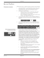
EQUIPMENT OVERVIEW
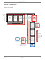
THEORY OF OPERATION
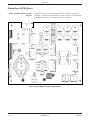
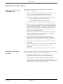
OVERALL BLOCK DIAGRAM
F
SpO2
EtCO2
C i r c u i t
BP2
Analog
Input
Hybrids
e
x
C
i
r
c
u
Main
Processing
Circuit
(MC68332)
DAS
Processing
Circuit
(MC68332)
Signal
Multiplexing
&
ADC
i
t
Expansion Interface
BP1
F l e x
Temp/CO
Patient Connectors
ECG/Resp
l
EtCO2
PCB
Assembly
NIBP
Isolated Power Supply
NOTE:
All supply voltages are sent to
the processor pcb assembly,
then dc power is distributed to
other electrical assemblies in
the monitor.
REVISION E
EAGLE 4000 PATIENT MONITOR
407300-123
Network
&
Serial
Comm.
Graphics
System
Processing
(TMS34010)
Front Panel
Flex
PCB
Assembly
Memory Card Slot
Communication PCB Assembly
Processor PCB Assembly
AC Powe r
Power
Supply
PCB
Assembly
D a t a Bu s
PCMCIA
Flex Circuit
Analog Out
User Panel
Defib Sync
NIBP Control
Acquisition PCB Assembly
Optional
Battery
Pack
16-ohm Speaker
Audio
ETHERNET
ASYNC COMM
ASYNC COMM
RMT VID
Display
Panel
Assembly
1 - 19
EQUIPMENT OVERVIEW
THEORY OF OPERATION (CONT)
OVERALL BLOCK THEORY
The block level theory of operation, as covered in this section, is
intended for service technicians and provides a general overview
of the monitor and its main electrical assemblies. An
understanding of the block level theory of operation is essential
for effectively installing, maintaining or troubleshooting the
monitor.
Power supply PCB assembly
The power supply PCB mounts internally to the monitor rear
casting assembly. The board accepts both low voltage AC power
from the main step down isolation transformer or 12 Vdc from
the optional battery pack. Both the step down transformer and
the battery pack are located off of the power supply PCB,
mounting into the rear casting assembly. The power supply PCB
provides four independent output voltages and appropriate power
control and status input/output (I/O) signals required by the
monitor electronic assemblies.
Acquisition PCB assembly
The acquisition PCB provides an electrically isolated patient data
acquisition system (DAS) to acquire real time patient data for the
monitor. Analog sensor/electrode patient input signals are
amplified and conditioned, then converted to digital data. The
digital patient data is transferred across an optically coupled
isolation barrier to the processor PCB for analysis and display.
The DAS consists of an isolated and non-isolated section which
are separated by a coupled inductor power supply and opticalisolation for signals crossing the barrier.
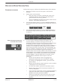
Processor PCB assembly
Communication PCB assembly
(Optional) End-tidal CO2 PCB
assembly
1 - 20
The processor PCB provides signal processing, system control,
user interface, and communications functions for the monitor,
both TFT color LCD and High-Bright EL display versions. It
receives and processes digitized patient data from the isolated
DAS assembly (acquisition PCB), text and waveform information
for the video display, interfaces with the operator via the front
panel switches and Trim Knob control, and communicates with
other products on the Ethernet network. Additional capabilities
include support for an external color CRT slave display
(functional only in color or "normal scan" mode) and a pair of
asynchronous communications ports for devices like a DDW
and/or remote control.
The communication PCB is responsible for the dispersion of
signals between the processor PCB and the monitor rear panel
connectors. Ethernet, remote video, asynchronous
communication, remote alarms and static protection are the
primary functions of the board.
The optional end-tidal CO2 PCB is designed to plug directly into
the expansion interface connector on the processor PCB
assembly. The main microcontroller on the processor PCB
controls the EtCO2 PCB assembly. This optional board provides
patient interface, signal acquisition and processing for all carbon
dioxide monitoring functions. The CO2 patient signals are
processed and stored by an on-board microcontroller. The
acquired CO2 data is then sent to the processor PCB for display,
communication and long-term patient data storage purposes.
EAGLE 4000 PATIENT MONITOR
407300-123
REVISION E
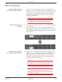
EQUIPMENT OVERVIEW
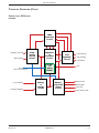
THEORY OF OPERATION (CONT)
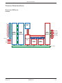
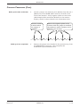
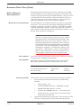
POWER SUPPLY PCB BLOCK
DIAGRAM
PWM
Controller
Circuit
Display On/Off
Shut Down
Power
Supply
On/Off
Control
Magnetics
&
Converter
Circuit
Bridge
&
ORing
Diodes
AC In
(From Transformer)
C/10 Enable
Charger Enable
REVISION E
Battery
&
Charger
Circuit
Post
Regulator
Circuit
+12V Analog
-12V Analog
+12V Main
+5V
Battery/
Line Power
Status
Circuit
NiCad Low
NiCad Fail
Line Clk
Line Power OK*
EAGLE 4000 PATIENT MONITOR
407300-123
1 - 21
EQUIPMENT OVERVIEW
THEORY OF OPERATION (CONT)
POWER SUPPLY PCB BLOCK
THEORY
Power supply PCB functional
circuits
Calibration
1 - 22
The power supply PCB mounts internally to the monitor rear
casting assembly. The board accepts both low voltage AC power
from the main step down isolation transformer or 12 Vdc from
the optional battery pack. Both the step down transformer and
the battery pack are located off of the power supply PCB,
mounting into the rear casting assembly. The power supply PCB
provides four independent output voltages and appropriate power
control and status input/output (I/O) signals required by the
monitor electronic assemblies.
Functional circuits on the power supply PCB include:
•
Power on/off control, and
•
Power forward converter/magnetics,
•
Pulse width modulation (PWM) controller,
•
Post regulator,
•
Battery and charger, and
•
Battery/line power status.
The calibration procedure for this assembly is found in the
section titled Calibration in this manual.
EAGLE 4000 PATIENT MONITOR
407300-123
REVISION E
EQUIPMENT OVERVIEW
THEORY OF OPERATION (CONT)
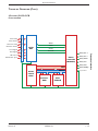
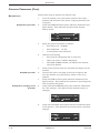
ACQUISITION PCB BLOCK
DIAGRAM
RA
RL
V3
V4
V5
Signal
Generation
(hybrids)
Analog
Signal
Multipexing
DAS
µController
(MC68332)
Data
V6
Isolation Barrier
V2
ECG Defib Protection
LL
V1
ADC Data
12-Bit
ADC
LA
DAS_FRZ
DAS_PCS0*
DAS_MISO
DAS_MISI
DAS_SCLK
Address
TEMP/CO
BP
SpO2
DAS Control
ASIC
Processor
RAM
Flash
EEPROM
NBP
Isolated Power Supply
REVISION E
EAGLE 4000 PATIENT MONITOR
407300-123
12V_MAIN
1 - 23
EQUIPMENT OVERVIEW
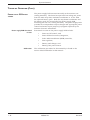
THEORY OF OPERATION (CONT)
ACQUISITION PCB BLOCK
THEORY
The acquisition PCB, or data acquisition system (DAS), located in
the monitor, is responsible for the acquisition of all vital-sign
patient data. Analog sensor/electrode input signals are
amplified and conditioned by hybrid assemblies, then converted
to digital data. The digital patient data is transferred across an
isolation barrier via high-speed opto-couplers to the processor
PCB for analysis and display.
The DAS consists of an isolated and non-isolated section which
are separated by a barrier that is capable of withstanding up to
6000 Vdc with respect to earth ground. Isolation is
accomplished by using a coupled inductor power supply and
opto-isolation for signals crossing the barrier.
Functional circuits
Calibration
1 - 24
Functional circuits on the acquisition PCB include:
•
Isolated power supplies generation,
•
Patient input connector interface,
•
ECG defibrillator protection,
•
Patient signal generation (hybrids interface),
•
Analog-to-digital conversion (patient signals),
•
DAS microcontroller and processing, and
•
DAS communication interface (isolation barrier).
The calibration procedure for this assembly is found in the
section titled Calibration in this manual.
EAGLE 4000 PATIENT MONITOR
407300-123
REVISION E
EQUIPMENT OVERVIEW
THEORY OF OPERATION (CONT)
PROCESSOR PCB BLOCK
DIAGRAM
Flash
Program
Memory
Bus
Control
EPLD
DAS_FRZ
DAS_PCS0*
DAS_MOSI
MC68332
Buffer
DAS_MISO
DAS_SCLK
32-Bit
Integrated
µController
Serial
Async
Comm
Interface
I/O
Address
Driver
LA0-23
I/O
Data
Xcvr.
LD0-15
DAS_ENBL*
IOA0-15
Ethernet
Xcvr
Interface
IOD0-15
COMM_TX1±
COMM_RX1
COMM_TX2±
COMM_RX2
+12VMAIN±
LAN_RX±
LAN_TX±
LAN_CD±
Compressor
3V / 1AH
Lithium
Battery
RA1-19
RAM
Data
Xcvr.
RD0-15
Expansion
Interface
Address
Driver
XA1-19
Expansion
Interface
Data
Xcvr.
XD0-15
Solenoid Valve1
System
Interface
ASIC
Defib Sync Jack
User
Panel
Interface
Trim Knob Control
Front Panel Pushbuttons
Analog
Output
(DAC)
Memory
Card
Interface
TMS34010
Graphics
System
Processor
(GSP)
Pressure Switches
Solenoid Valve0
Expansion Interface
RAM
Address
Driver
NBP
Interface
ASIC
Battery Backed SRAM
µProcessor
Supervisory
Circuit
50 MHz
Oscillator
High Freq Isolation Region
Crystal
Oscillator
(31.2 kHz)
RTC
&
Audio
XA1-19
XD0-15
PCMCIA
Card
Slot
16Ω Speaker
LAD0-15
GD0-15
WUA0-9
GSP
Program
DRAM
+5VID/±12VID
GSP
Memory
Interface
Logic
Text
VRAM
TD0-15
EPD0-7
TA0-7
External
Display
Interface
RMT_RED/GREEN/BLUE_VID
RMT_HSYNC*/VSYNC*
Graphics
Controller
ASIC
Waveform
VRAM
RMT_ID
Internal Display Backlight Power
WD0-15
IPD0-7
WLA0-7
Internal
Display
Interface
D0-7
Internal Display Data
Internal Display Power
Internal Display Control
REVISION E
EAGLE 4000 PATIENT MONITOR
407300-123
1 - 25
EQUIPMENT OVERVIEW
THEORY OF OPERATION (CONT)
PROCESSOR PCB BLOCK THEORY
Functional circuits
The processor PCB provides signal processing, system control,
user interface, and communications functions for the monitor,
both TFT color LCD and High-Bright EL display versions. It
receives and processes digitized patient data from the isolated
DAS assembly (acquisition PCB), text and waveform information
for the video display, interfaces with the operator via the front
panel switches and Trim Knob, and communicates with other
products on the network using a built-in Ethernet interface.
Additional capabilities include support for an external color CRT
slave display (functional only in color or "normal scan" mode)
and a pair of asynchronous communications ports for devices
like a DDW and/or remote control.
As a result of the complexity of this board, there are many
functional circuits. The functional circuits on the processor PCB
include:
•
Main processing circuit:
»
»
»
»
»
»
»
•
Serial asynchronous serial communications interface
DUART (ASYNC COMM ports),
•
Serial network interface controller (ETHERNET port),
•
Non-invasive blood pressure (NBP) interface ASIC,
•
Analog output 12-bit DAC (ECG and blood pressure),
•
Real-time clock/calendar and audio generation,
•
User panel interface (Trim Knob control/push-buttons),
•
Memory card (PCMCIA) interface,
•
Video processing circuit (waveforms and text for display):
»
»
»
»
»
»
»
»
»
•
Calibration
1 - 26
Motorola MC68332 32-bit integrated microcontroller
(19.968 MHz internally),
Clock - 31.2 kHz crystal oscillator,
Bus control EPLD,
Microprocessor support circuit (watchdog) and 3 volt
lithium battery,
Flash EEPROM (4 megabytes),
Static RAM (2 megabytes),
System interface ASIC.
Texas Instruments TMS34010 graphics co-processor (50
MHz),
Clock - 50 MHz CMOS/TTL oscillator,
Video control LCA,
Graphics system processor memory interface LCA,
Graphics system processor program memory - DRAM (512
kilobytes),
Waveform display memory - VRAM (256 kilobytes),
Text display memory - VRAM (256 kilobytes),
Display driver circuit,
Remote display video interface (RMT VID port).
DAS interface and power supply interface.
The calibration procedure for this assembly is found in the
section titled Calibration in this manual.
EAGLE 4000 PATIENT MONITOR
407300-123
REVISION E
EQUIPMENT OVERVIEW
THEORY OF OPERATION (CONT)
(OPTIONAL) ETCO2 PCB
BLOCK DIAGRAM
Case heater
Detector temp
Detector heater
CO2 signal
Ref signal
Barometric pres
SRXD
STXD
12-Bit
ADC
SCLK
ADCCS*
EXP_PS0-3
EtCO2
µController
(MC68332)
EXP_ID0-3
EXP_HRST*
EXP_TXD
EXP_RXD
Data
Address
EtCO2
Control
EPLD
Processor
RAM
REVISION E
EXP_MSIRQ*
+5/+12 V
Flash
EEPROM
EAGLE 4000 PATIENT MONITOR
407300-123
1 - 27
Expansion Interface
IR source
Signal/Control Circuitry
Case temp
EQUIPMENT OVERVIEW
THEORY OF OPERATION (CONT)
(OPTIONAL) ETCO2 PCB
BLOCK THEORY
Reference
Detector
Ref Signal
Gas
to
be
Analyzed
IR
Source
CO2
Detector
CO2 Signal
Optical
Beam
Splitter
EtCO2 Transducer Head
Functional circuits
The Eagle Capnostat CO2 System (ECCS) is a self-contained
printed circuit assembly that interfaces Novametrix Capnostat 3
sensors to the Eagle 4000 Patient Monitor. The ECCS has the
necessary circuitry to interface to the Capnostat 3. It acquires
raw signals from the Capnostat 3, processes these signals to
produce CO2 waveform data and respiration parameters. These
parameters are sent to the host system via an asynchronous
serial communication link.
The Mainstream Capnometer measures End-tidal Carbon Dioxide
using a non-invasive technique that relies on the selective
absorption properties of CO2 to specific frequencies of infrared
radiation. In the transducer head, a thick film infrared source is
pulsed at a rate of approximately 87 Hz, generating a broad band spectrum of IR. Selective filtering separates this into two
narrow regions, one inside the band of CO2 absorption, the other
outside the region of CO2 absorption. Behind each filter is a
detector which produces an electrical signal proportional to the
amount of light energy it receives. The detector associated with
the filter outside the band of CO2 absorption always records the
maximum level of the source energy since the signal it receives is
not affected by CO2. As the level of CO2 increases, more of the
light energy is absorbed by the CO2 gas molecules in the airway
and less signal reaches the detector. This signal, inverted by the
detector is referred to as the CO2 Input signal. To acquire a
precise level of CO2, both channels are sampled simultaneously
and the level of CO2 in the sampling chamber is determined from
the ratio of CO2 Input and Reference channels. The ratio is
compared to a lookup table in memory to establish the correct
value in units of mmHg (which can be converted to units of kPa
or %).
The functional circuits on the EtCO2 PCB include:
•
Signal/control circuitry
»
Power Converter Circuit
»
Source Pulser
»
Heater Circuits
»
Pump circuitry
»
Barometric pressure measurement
•
Analog to digital conversion circuit.
•
EtCO2 microcontroller circuit,
»
Motorola MC68332 32-bit integrated microcontroller
running at the clock rate of 15.9744 MHz from the
crystal frequency of 31.2 kHz
»
Time processing unit (TPU) channels
»
Memory,
Flash EEPROM; 128 kB; 80 ns,
SRAM; 128 kB; 80 ns,
Serial EEPROM.
•
1 - 28
EtCO2 control EPLD,
EAGLE 4000 PATIENT MONITOR
407300-123
REVISION E
EQUIPMENT OVERVIEW
THEORY OF OPERATION (CONT)
Calibration
REVISION E
The calibration procedure for the EtCO2 PCB assembly is found
in the section titled Calibration in this manual.
EAGLE 4000 PATIENT MONITOR
407300-123
1 - 29
EQUIPMENT OVERVIEW
For your notes.
1 - 30
EAGLE 4000 PATIENT MONITOR
407300-123
REVISION E
2
MAINTENANCE
Maintenance Schedule ....................................................... 2-2
Manufacturer recommendation ................................... 2-2
Manufacturer responsibility ........................................ 2-2
Visual Inspection ............................................................... 2-3
Inspecting the monitor ................................................ 2-3
Cleaning The Monitor ........................................................ 2-4
Cleaning the display .................................................... 2-4
Cleaning the external surfaces .................................... 2-4
Manufacturer recommendation ................................... 2-4
Checkout Procedures ......................................................... 2-5
About the checkout procedures ................................... 2-5
Manufacturer recommended test equipment................ 2-5
Power-up self-test ....................................................... 2-6
ECG tests .................................................................... 2-7
12SL ECG tests ........................................................... 2-9
Respiration tests ....................................................... 2-10
Temperature tests ..................................................... 2-11
Cardiac output tests .................................................. 2-12
Invasive blood pressure tests ..................................... 2-13
Pulse oximetry tests .................................................. 2-15
Non-invasive blood pressure tests ............................. 2-17
End-tidal carbon dioxide tests ................................... 2-22
Defib synch tests ....................................................... 2-24
Battery tests ............................................................. 2-26
Speaker tests ............................................................ 2-27
Checkout procedure completion ................................ 2-27
Electrical Safety Tests ..................................................... 2-28
Current leakage tests ................................................ 2-28
Wall receptacle tests .................................................. 2-29
Surface continuity tests ............................................ 2-29
Ground wire to ground tests ...................................... 2-30
Chassis to ground tests ............................................. 2-31
Patient source tests ................................................... 2-32
Patient sink tests ...................................................... 2-34
Test completion ......................................................... 2-35
Hi-Pot (Dielectric Withstand) Tests ............................ 2-36
REVISION E
EAGLE 4000 PATIENT MONITOR
407300-123
2-1
MAINTENANCE
MAINTENANCE SCHEDULE
MANUFACTURER
RECOMMENDATION
To make sure the monitor remains in proper operational and
functional order, a good maintenance schedule must be adhered
to. The manufacturer's recommendations in this regard is as
follows:
•
Inspection: Operators should perform this prior to
admitting each patient to the monitor. Service personnel
should perform this prior to servicing the monitor.
•
General Cleaning: Operators should perform this prior to
admitting each patient to the monitor. Service personnel
should perform this after servicing the monitor.
•
Checkout Procedures: These should be performed by
qualified service personnel upon receipt of the equipment,
one time per year thereafter, and each time the monitor is
serviced.
•
Leakage Current Tests: These should be performed by
qualified service personnel upon receipt of the equipment,
one time per year thereafter, and each time the monitor is
serviced.
•
Hi-Pot Tests: High-potential tests should be performed by
qualified service personnel whenever a circuit board is
removed, repaired or replaced in the monitor. These tests
should also be performed if any component or assembly
effecting patient isolation is removed, repaired or replaced
in the monitor.
NOTE
The Hi-Pot Tests provide a means of checking the
patient isolation circuitry such that a patient receiving defibrillation, while attached or admitted to the
monitor, will receive the full energy of each shock and
that the monitor will not absorb the energy, when
delivered.
MANUFACTURER RESPONSIBILITY
2-2
Failure on the part of all responsible individuals, hospitals or
institutions, employing the use of this monitor, to implement the
recommended maintenance schedule may cause equipment
failure and potential operator and patient health hazards. The
manufacturer does not in any manner, unless an Equipment
Maintenance Agreement exists, assume the responsibility for
performing the recommended maintenance schedule. The sole
responsibility rests with all individuals, hospitals, or institutions
utilizing the monitor.
EAGLE 4000 PATIENT MONITOR
407300-123
REVISION E
MAINTENANCE
VISUAL INSPECTION
The monitor should be carefully inspected prior to each patient
being admitted to the monitoring system. Follow these
guidelines when inspecting the equipment:
INSPECTING THE MONITOR
70
5
-BED
SICU
ED
RG
HA
RO
DISC
RO
60
10
D
BP
TH
XT
NE W
DO
S&
LC S
CA ORIE
HIST
WIN
Y
LA
DISPONS
TI
OP
H&
AP
GR MS
AR
AL
V
32.4
160
1
•
Inspect all front and rear panel external connectors for
damaged pins, prongs and connector housings. Refer
damaged equipment to qualified service personnel for repair
before using the monitor on a patient.
•
Inspect all cables, insulation, strain-reliefs and connectors
for damage, cracks or degradation. Refer damaged
equipment to qualified service personnel for repair before
using the monitor on a patient.
P
A
2
Hg
mm
ZE
R
NITO
HT
LIG reen)
E MO
HIGH sc
to e of n).
ob sid
ER
Kn ht scree
OP
m r rig m of
Tri
the els (fa(botto
r
TE
ete ns
TA r lab ns
tio
RO ete optio
op
param
nu
d.
nu
CT
param
LE me the playe
me
SE ed
and
to Relat ribingis dis
ob
Kn ns. e desc tion
m
.
Tri optio e lin nu op
nu
ag
me
S themenu ss ted me
in
ES d
me
.
ma
PR an A hligh
nu
to
els ar.
me
lab appe a hig
us
urn
of
ret
vio
y an
will on
pla
t to
y pre
cti
lec
dis
pla
fun
Se
will
dis
IN
nu
t to
MA
lec
NU
p me
ME
Se
E
pu
US
OS
a po
VIO
CL W
m
PRE NU
DO
fro .
ME
LP
WIN
HE ndow
ting wi
lec on
Se ati
inform
ING
AT
A
R
1
Hg
mm
ZE
II
Carefully inspect the monitor for obvious physical damage
to the outer case, display screen and controls. Do not use
the monitor if physical damage is determined. Refer
damaged equipment to qualified service personnel for repair
before using the monitor on a patient.
TIN
MAR
E
0
15 C
50 G
0
20
80
S
BP
•
°C
AR
20
0
60
2
42
30
C
O
30
5
R
R
PA
0
II
II
RR
T:
TIEN ED
RG
HA
PA
DISC
IZE
OM
ST
CU ITOR
MON
H
P
AP
GR/STO
GO
!
E
NC
LE M
SI AR
AL
P
NB
L
OB
IM
KN
TR
AL
RO
NC
ZE
. SY
FIB
TT
P P
NB TO
/S
O2
GO
SA
DE
BA
IL
FA
BP
NG
RG
CH
AC
R
Y
PW
RD
T
Y
LA
SP FF
DI /O
ON
ATED
ISOL
G
EC
REVISION E
BA
CO
P/
M
TE
BP
EAGLE 4000 PATIENT MONITOR
407300-123
2-3
MAINTENANCE
CLEANING THE MONITOR
CLEANING THE DISPLAY
To clean the display on the monitor, use a soft, clean , lint-free
cloth dampened with a glass cleaner similar to Windex, or a 1:1
mixture of isopropyl alcohol and water.
WARNING
Do not spray glass cleaner or general cleaning solutions directly onto the display. Do not use hospital
disinfectants, like Cidex, on the display.
Filter lens characteristics
CLEANING THE
EXTERNAL SURFACES
The monitor display uses a circular-polarized filter with antireflective (AR) coating, which is the exposed external surface.
This type of filter increases the display contrast while, at the
same time, reducing glare from ambient light sources. Upon
close inspection of this filter lens while the display is turned off,
milky-white streaks may be noticed. Visible streaks do not
indicate that the display needs to be cleaned. This phenomena is
inherent of displays incorporating this technology.
Clean the external surfaces of the monitor before each time a
patient is admitted to the system. The exterior surfaces may be
cleaned with a lint-free cloth dampened with one of these
approved solutions:
ammonia (diluted),
Cidex,
mild soap (dissolved), or
sodium hypochlorite bleach (diluted).
MANUFACTURER
RECOMMENDATION
The manufacturer recommends the following guidelines to avoid
damaging the monitor:
•
Dilute all cleaning solutions according to respective
manufacturer recommendations.
•
Use a clean, dry, lint-free cloth to wipe off excess cleaning
solution after each application.
•
Do not pour water or cleaning solutions directly onto the
monitor. Do not allow fluids to run into crevices,
connectors or cooling vents on the monitor.
•
Never use these cleaning agents:
abrasive cleaners or solvents of any kind,
alcohol-based cleaning agents,
wax containing a cleaning substance,
acetone, or
betadine.
CAUTION
Follow these cleaning instructions exactly. Failure
to follow the instructions may melt, distort, or dull
the finish of the case, blur lettering on the labels, or
cause equipment failures.
2-4
EAGLE 4000 PATIENT MONITOR
407300-123
REVISION E
MAINTENANCE
CHECKOUT PROCEDURES
ABOUT THE CHECKOUT
PROCEDURES
This part of the section contains all of the checkout procedures
for the monitor. The checkout procedures provide service
personnel with a method of verifying operational and functional
performance of the monitor without having to disassemble the
unit. Failure to attain the prescribed results indicates a need for
calibration or potential malfunction of the monitor.
Perform the checkout procedures upon receipt of the monitor,
every year thereafter, and each time a circuit board is removed or
replaced.
The checkout procedures are based on the assumption that the
monitor being tested is used with known, good cables and test
equipment. It also requires that the user be somewhat familiar
with the operation of the monitor and all test equipment used for
the checkout procedures. For more information concerning the
operation of these components, refer to the respective operator
manual.
MANUFACTURER RECOMMENDED
TEST EQUIPMENT
The following table lists the manufacturer's recommended test
equipment, adaptors, and cables necessary to successfully
complete the checkout procedures. The checkout procedures
were written for the test equipment in the following table. If test
equipment other than the manufacturer's recommendation is
used, it may be necessary to slightly modify some test steps.
Description
Multifunction Microsimulator
Qty
MARQ1
1
Multi-Link ECG cable, 5-Lead, AHA
412931-001
1
Multi-Link ECG cable, 12-Lead, AHA
416035-001
1
Multi-Link Leadwire Set, 5-Lead, AHA
414556-001
1
Multi-Link Leadwire Set, V-Leads, AHA 415467-003
1
BP Adapter
700095-001
2
Temperature Adaptor
402015-004
1
6770031
1
Cardiac Output Simulator II
900028-001
1
CO Adaptor
700092-001
1
SenSym 1200
1
SpO2 Simulator
408610-001
1
SpO2 Simulator Cable, Nellcor
700232-004
1
Capnostat (CO2) Sensor Cable
412340-001
1
TEMP-to-Simulator Cable
Mercury manometer
REVISION E
Part Number
EAGLE 4000 PATIENT MONITOR
407300-123
2-5
MAINTENANCE
CHECKOUT PROCEDURES (CONT)
The following steps are used to run the monitor power-up self
tests.
POWER-UP SELF-TEST
PWR
AC
BATT
RDY
PWR
AC
BATT
RDY
2-6
BATT
CHRGNG
FAIL
BATT
CHRGNG
1.
Turn the monitor rear panel power switch to the off (0)
position.
2.
If the display is on, press the DISPLAY ON/OFF key to turn
it off.
3.
Connect a power cord between a properly wired wall
receptacle and the monitor power connector.
4.
Turn the monitor rear panel power switch to the on (1)
position.
5.
Verify all of the front panel indicators illuminate for a
second or two.
6.
Verify the PWR-AC indicator stays illuminated.
7.
For monitors with the optional battery installed, verify one
of the BATT indicators stays illuminated.
•
If the RDY indicator is on, continue with the tests.
•
If the CHRGNG indicator is on, wait for the battery to
fully charge and the RDY indicator to illuminate.
•
If the FAIL indicator is on, replace the battery as
described in the Battery Failure portion of Section 4:
Troubleshooting.
FAIL
EAGLE 4000 PATIENT MONITOR
407300-123
REVISION E
MAINTENANCE
CHECKOUT PROCEDURES (CONT)
Follow these steps to perform the ECG tests.
ECG TESTS
1.
2.
Set up the patient simulator as follows:
•
Heart rate - 80 BPM,
•
Heart rate amplitude - 1.0 mV,
•
5-Lead ECG patient cable properly attached.
Attach the ECG patient cable and ECG leadwire set to the
ECG/RESP connector on the monitor and the leadwire
connectors on the top of the patient simulator.
ECG test setup
Multi-Link ECG Cable Part Numbers:
AHA
IEC
5-Lead
412931-001 412931-002
12-Lead 416035-001 416035-002
V
H
P
AP
GR/STO
GO
!
E
NC
LE M
SI AR
AL
P
NB
L
OB
IM
KN
TR
AL
RO
NC
ZE
. SY
FIB
DE
P P
NB TO
/S
O2
GO
TT
SA
BA
IL
FA
BP
NG
RG
CH
AC
R
BP
Y
PW
RD
T
BA
Y
LA
SP FF
DI /O
ON
O
/C
MP
TE
TED
ISOLA
G
EC
Patient Simulator,
PNMARQ1
C
AD
LE INU
NT
CO
/V
1
ITY
SY
ST
OL
0
2.
E
5
0.
L
E
G
A
C
0
1.
R
A
P
E
S
40
N
R
IO
L
D
L
T
G
NE
O
A
S
R
L
E
T
A
P
m
1 A
C
VP 2 E
VP S
AV
NE
R
U
EC
AP
0
75
G
Hg
T
PU
10
E
12
5
0.
A
AV
NE
W
0
AP
1
0.
TEM
RABP
0
E
25 LINE
NC
SE DA
BA PE MS
OH
IM
UT
S
O mm
PO G
NE 0
20 0
15 0
10
50
30
m
H
50
12
0 B
16 0 P
M
12
80
IR
O
P
L
S
CT
LE
SE
E
B
TY
RI
S LA
PO PO
1 E
0. UD
IT
PL mV
AM
R
EC
T
M
15
MS
P
0
2.
30
E
C
30
˚
40 ˚
37 ˚
0 B
60
OH
T
P
A
AD
LE
R 0
E 4.
10 .6
98 .0
86
II
IC
M
P
E
O
T
I&
W
LO T.
BA
T
U
R
E
III
CT
LE
SE
40
N
O
ER
W
FF
O PO
30
C
ES
F GRE
DE
37
400
——
PRBLOO
ES D
TE SE
SU
MP RIE
120
RE
S ——
/80 1
OUERAT
TP UR 700
UT E
PRBLOO
ES D
SU
30/ RE
10 2
Multi-Link Leadwire Set:
AHA Colors IEC Colors
5-Lead
414556-001 414556-003
V-Leads 415467-003 415467-004
ECG waveform, heart rate and
QRS tones
3.
Admit the patient simulator to the monitor.
4.
Observe the following:
5.
REVISION E
•
ECG lead II is displayed and is noise-free,
•
Heart rate of 80 ±1 BPM is displayed,
•
With QRS tones enabled, an audible tone sounds with
each R-Wave (QRS complex).
Verify all seven ECG leads are available for viewing and are
noise-free.
EAGLE 4000 PATIENT MONITOR
407300-123
2-7
MAINTENANCE
CHECKOUT PROCEDURES (CONT)
Pacemaker detection test setup
Lead-fail detection test setup
Calibration pulse test setup
6.
Select DETECT PACE and set to NORMAL.
7.
Select the VP2 pacemaker pulse on the simulator.
8.
Observe the following while viewing ECG leads II, III, aVR,
aVF, and V:
9.
•
a P appears above the PVC count indicating
pacemaker pulse detection is enabled, and
•
the heart rate still reads 80 ±1 BPM.
Disable pacemaker pulse detection on the monitor and
return the simulator to these conditions:
•
Heart rate - 80 BPM,
•
Heart rate amplitude - 1.0 mV,
•
5-Lead ECG patient cable properly attached.
10.
Select ECG lead II for viewing in the top trace position on
the monitor display.
11.
Disconnect the RA leadwire from the patient simulator.
12.
Observe following:
•
a RA FAIL message appears on the display, and
•
lead III automatically displays in place of lead II in the
top trace position.
13.
Reconnect the RA leadwire to the patient simulator.
14.
Inject a 1 mV calibration signal using the patient simulator
and start a manual graph.
15.
Observe that the calibration pulse is properly displayed and
graphed (see figure below).
16.
This completes the ECG tests. Continue to the next steps
of these checkout procedures.
Graphed cal pulses
ECG test completion
2-8
EAGLE 4000 PATIENT MONITOR
407300-123
REVISION E
MAINTENANCE
CHECKOUT PROCEDURES (CONT)
12SL ECG TESTS
Follow these steps to perform the 12SL ECG tests.
1.
REVISION E
Set up the patient simulator as follows:
•
Heart rate - 80 BPM,
•
Heart rate amplitude - 1.0 mV,
•
12-Lead ECG patient cables properly attached.
2.
Attach the ECG patient cable and ECG leadwire sets to the
ECG/RESP connector on the monitor and the leadwire
connectors on the top of the patient simulator.
3.
Admit the patient (simulator) to the monitor.
4.
From the Main Menu of the monitor, rotate the Trim Knob
to highlight the ECG parameter box then press the Trim
Knob to select it.
5.
Select 12 LEAD ECG ANALYSIS from the ECG parameter
menu option items.
6.
Observe the 12 ECG traces are noise-free and properly
displayed,
EAGLE 4000 PATIENT MONITOR
407300-123
2-9
MAINTENANCE
CHECKOUT PROCEDURES (CONT)
RESPIRATION TESTS
Respiration tests setup
ECG lead II respiration test
Using the same test setup as used for the ECG tests, follow these
steps to perform the respiration tests.
1.
2.
3.
ECG lead I respiration test
Respiration tests completion
2 - 10
With the ECG patient cable attached to the ECG/RESP
connector of the monitor, setup the patient simulator as
follows:
•
Respiration (RESP) baseline impedance - 750Ω,
•
RESP ∆R - 0.5Ω,
•
RESP lead select - I & II,
•
RESP rate (respirations per minute) - 30.
Set up the monitor as follows:
•
RESP waveform - on,
•
RESP waveform lead select - lead II (RESP waveform
derived from ECG lead II).
Observe the following:
•
RESP parameter window appears on the monitor with
a reading of 30 ±2 (respirations per minute),
•
RESP waveform appears distortion-free on the
monitor.
4.
Change the RESP waveform lead select of the monitor to
lead I (RESP waveform derived from ECG lead I).
5.
Observe the following:
6.
•
RESP parameter window appears on the monitor with
a reading of 30 ±2 (respirations per minute),
•
RESP waveform appears distortion-free on the
monitor.
Disconnect the ECG patient cable from the ECG/RESP
connector of the monitor. Proceed to the next steps in
these checkout procedures.
EAGLE 4000 PATIENT MONITOR
407300-123
REVISION E
MAINTENANCE
CHECKOUT PROCEDURES (CONT)
TEMPERATURE TESTS
T1 temperature setup
Follow these steps to perform the temperature tests.
1.
Set up the patient simulator for a temperature output of
37°C.
2.
Attach the temperature adaptor cable to the TEMP/CO
connector of the monitor (see figure below).
3.
Set the switch on the temperature adaptor to the 400
position.
4.
Attach the temperature simulator cable from the SERIES
400 TEMPERATURE OUTPUT connector of the patient
simulator to the T1 connector of the temperature adaptor.
Temperature tests setup
V
H
AP P
GR/STO
GO
!
E
NC
LE M
SI AR
AL
P
OB
IM
NB
KN
TR
L
AL
RO
NC
ZE
. SY
FIB
DE
P P
NB TO
/S
O2
GO
SA
TT
BA
IL
FA
BP
NG
RG
CH
AC
R
BP
Y
PW
RD
T
BA
Y
LA
SP FF
DI /O
ON
O
/C
MP
TE
ATED
ISOL
G
EC
Temperature Adapter,
PN402015-001
Patient Simulator,
PNMARQ1
C
AD
LE IN
NT
CO
UI
/V
Temperature
Simulator Cable,
PN6770031
1
TY
SY
ST
OL
0
2.
E
5
0.
L
E
G
A
C
0
1.
A
P
R
E
S
40
N
80
IO
L
D
L
T
G
E
N
O
A
0 B
16 0 P
M
12
IR
O
P
L
S
T
C
LE
E
S
E
B
Y
IT
R
S LA
O
P PO
R
1 E
0. D
TU
LI
P mV
M
A
R
S
R
L
A
E
R
U
NE
m
T P
EC 1 A
C
VP 2 E
VP
VS
A
AP
H
G
IM
30
OH
10
W
PN
0
A
A
VE
12
5
0.
EA
1
0.
TE
AM
R BP
T
U
TP Hg
0 E E
25 LIN C
E N
S A
A D
B PE MS
0
75
U
S
O mm
PO
EG
N 0
20 0
15 0
10
50
m
50
12
60
EC
T
M
15
P
˚
40 ˚
37 ˚
30
0 B
MS
0
2.
30
OH
E
C
T
P
E
II
IC
M
P
E
O
T
I&
R
A
T
U
R
E
III
T
C
LE
E
S
40
0
4.
10 .6
98 .0
86
D
A
LE
W
LO T.
A
B
37
N
O
R
E
W
FF O
O P
30
C
S
E
E
F GR
E
D
40
0 ——
PRBLOO
ES D
TE SE
SU
MP RIE
120
RE
S ——
/80 1
OUERAT
TP UR 70
UT E 0
PRBLOO
ES D
SU
30/ RE
10 2
T2 temperature setup
Temperature tests completion
REVISION E
5.
Verify a TEMP parameter window appears on the monitor
display with a T1 reading of 37.0° ±0.4° C.
6.
Move the temperature simulator cable from the T1
connector of the temperature adaptor to the T2 connector of
the temperature adaptor.
7.
Verify a T2 reading of 37.0° ±0.4° C in the TEMP parameter
window on the monitor display.
8.
Remove the temperature adaptor and temperature
simulator cable from the monitor and patient simulator.
EAGLE 4000 PATIENT MONITOR
407300-123
2 - 11
MAINTENANCE
CHECKOUT PROCEDURES (CONT)
CARDIAC OUTPUT TESTS
Follow these steps to perform the cardiac output tests.
1.
Connect the cardiac output (CO) cable adaptor to the
TEMP/CO connector of the monitor.
2.
Connect a simulator cable between the CO cable adaptor
and the CO simulator.
CO test setup
V
H
AP
GR/STO
GO
P
!
E
NC
LE M
SI AR
AL
P
NB
AL
ZE
TR
L
RO
IM
KN
OB
NC
. SY
FIB
TT
P P
NB TO
/S
O2
GO
DE
SA
BA
IL
FA
BP
NG
Cardiac Output
Cable Adapter,
PN700092-001
RG
CH
AC
R
Y
PW
BP
RD
T
Y
LA
SP FF
DI /O
ON
BA
O
/C
MP
TE
ATED
ISOL
G
EC
T
C
JE
IN
P
M
29
.6
24
O
30
<
C
JE
4
1
W
A
SH
O
SE UT
LE C
C U
T RV
E
2
3
IN
<
–2
0
TA
TE
TE
8
M
P
˚C
>
30
15
B
LO
D
TE
35
30 .1
.3
˚C
>
42
36
41
.7
37
C
BA HA
TT NG
ER E
Y
C
A
R
SIM D
IA
U C
LA O
TO U
R TPU
II T
Cardiac Output
Simulator II,
PN900028-001
Blood temperature test
3.
Set the CO simulator to output blood temperature (BT)
readings. Verify a CO parameter window appears on the
monitor display with BT readings in the ranges as shown in
the table below:
Simulator BT Setting
30.3°C
35.1°C
36.0°C
37.0°C
41.7°C
Injectate temperature test
4.
Set the CO simulator to output injectate temperature (IT)
readings. Verify a CO parameter window appears on the
monitor display with IT readings in the ranges as shown in
the table below:
Simulator IT Setting
0.0°C
8.0°C
15.0°C
24.0°C
29.6°C
CO test completion
2 - 12
5.
Monitor BT Reading Range
30.1 – 30.5
34.9 – 35.3
35.8 – 36.2
36.8 – 37.2
41.5 – 41.9
Monitor IT Reading Range
–0.3 – +0.3
7.7 – 8.3
14.7 – 15.3
23.7 – 24.3
29.3 – 29.9
Disconnect the CO cable adaptor from the TEMP/CO
connector of the monitor. This completes the CO tests.
EAGLE 4000 PATIENT MONITOR
407300-123
REVISION E
MAINTENANCE
CHECKOUT PROCEDURES (CONT)
INVASIVE BLOOD PRESSURE TESTS
The invasive blood pressure (BP) tests provide a method of
verification for both BP connectors (BP1 and BP2) of a monitor
equipped with this optional function. Follow these steps:
1.
BP1 connector (AR1) tests
Set up the patient simulator as follows:
2.
•
Blood pressure (BP) polarity - POS,
•
BP output - 0 mmHg.
Connect the BP simulator cable from the BLOOD
PRESSURE 1 - 120/80 connector of the patient simulator
to the BP1 (left-most BP) connector of the monitor.
BP test setup
Blood Pressure
Simulator Cable,
PN700095-001
V
H
AP P
GR/STO
GO
!
E
NC
LE M
SI AR
AL
P
NB
TR
L
KN
IM
OB
AL
RO
NC
ZE
. SY
FIB
TT
DE
P P
NB TO
/S
O2
GO
SA
BA
IL
FA
BP
NG
RG
CH
AC
R
Y
PW
BP
RD
T
Y
LA
SP FF
DI /O
ON
BA
O
/C
MP
TE
ATED
ISOL
G
EC
C
AD
LE IN
NT
CO
/V
UI
1
TY
SY
ST
OL
0
2.
E
5
0.
L
E
G
A
C
0
1.
R
A
P
E
S
40
N
R
IO
L
D
L
T
G
E
N
O
A
S
R
L
A
E
R
U
NE
G
T P
EC 1 A
C
VP 2 E
VP
VS
A
AP
0
75
T
U
TP Hg
W
PN
0
A
A
VE
12
5
0.
EA
1
0.
TE
AM
R BP
0 E E
25 LIN C
E N
S A
A D
B PE MS
OH
IM
U
S
O mm
PO
EG
N 0
20 0
15 0
10
50
m
30
m
H
10
50
12
0 B
16 0 P
M
12
80
IR
O
P
L
S
T
C
LE
E
S
E
B
Y
IT
R
S LA
O
P PO
1 E
0. D
TU
LI
P mV
M
A
R
60
T
M
15
P
EC
30
E
C
30
˚
40 ˚
37 ˚
0 B
MS
0
2.
OH
T
P
A
T
R
E
III
T
C
LE
E
S
U
D
A
LE
R 0
E 4.
10 .6
98 .0
86
II
IC
M
P
E
O
T
I&
W
LO T.
A
B
40
37
30
N
O
R
E
W
FF O
O P
C
S
E
E
F GR
E
D
Patient Simulator,
PNMARQ1
40
0 ——
PRBLOO
ES D
TE SE
SU
MP RIE
120
RE
S ——
/80 1
OUERAT
TP UR 70
UT E 0
PRBLOO
ES D
SU
30/ RE
10 2
3.
Verify the AR1 parameter window, waveform label,
corresponding graticules, and waveform appear on the
monitor display, along with a BP waveform requiring zero
reference.
Zero-reference AR1
4.
Press the ZERO ALL push-button on the front panel of the
monitor to zero-reference the AR1 BP waveform.
Static pressure verification
5.
Change the patient simulator BP output to 200 mmHg.
6.
Observe a reading of 200/200 (200) ± 4 mmHg in the AR1
parameter window on the monitor display.
7.
Change the patient simulator BP output to WAVE
(simulated BP waveform).
8.
Set the AR1 BP waveform gain on the monitor to auto.
9.
Observe a distortion-free AR1 BP waveform and a reading of
approximately 120/80 (93) in the AR1 parameter window
on the monitor display.
10.
Disconnect the BP simulator cable from the BP1 connector
of the monitor. Continue to the next step for the BP2 test.
Dynamic pressure verification
BP1 test completion
REVISION E
EAGLE 4000 PATIENT MONITOR
407300-123
2 - 13
MAINTENANCE
CHECKOUT PROCEDURES (CONT)
BP2 connector (PA2) tests
Set up the patient simulator as follows:
•
BP polarity - POS,
•
BP output - 0 mmHg.
12.
Connect the BP simulator cable to the BP2 (right-most BP)
connector of the monitor.
13.
Verify a PA2 parameter window, waveform label and
corresponding graticules appear on the monitor display,
along with a PA2 BP waveform requiring zero reference.
Zero-reference PA2
14.
Press the ZERO ALL push-button on the front panel of the
monitor to zero reference the PA2 BP waveform.
Static pressure verification
15.
Change the patient simulator BP output to 200 mmHg.
16.
Observe a reading of 200/200 (200) ± 4 mmHg in the PA2
parameter window on the monitor display.
17.
Change the patient simulator BP output to WAVE
(simulated BP waveform).
18.
Set the PA2 BP waveform gain on the monitor to auto.
19.
Observe a distortion-free PA2 BP waveform and a reading of
approximately 120/80 (93) in the PA2 parameter window on
the monitor display.
20.
Remove the BP simulator cable from the BP2 connector of
the monitor. This completes the BP tests.
Dynamic pressure verification
Invasive BP test completion
2 - 14
11.
EAGLE 4000 PATIENT MONITOR
407300-123
REVISION E
MAINTENANCE
CHECKOUT PROCEDURES (CONT)
PULSE OXIMETRY TESTS
Follow these steps to perform the pulse oximetry (SpO2) tests.
1.
Set the SpO2 simulator power switch to the off position.
2.
Connect the Nellcor-style SpO2 simulator cable between the
SpO2 connector of the monitor and the SpO2 simulator as
shown below.
SpO2 test setup
V
H
AP P
GR/STO
GO
!
E
NC
LE M
SI AR
AL
P
NB
L
IM
TR
OB
KN
AL
RO
NC
ZE
. SY
FIB
TT
P P
NB TO
/S
O2
GO
SA
DE
BA
IL
FA
BP
NG
RG
CH
AC
R
Y
PW
BP
RD
T
Y
LA
SP FF
DI /O
ON
BA
O
/C
MP
TE
ATED
ISOL
G
EC
Nellcor-style SpO2
simulator cable,
PN700232-004.
SpO2 percentage accuracy
verification
3.
Set up the SpO2 simulator as follows:
•
SpO2 - 99% (using the white NELLCOR values),
•
PULSE RATE - 100 B/M (beats per minute),
•
MODE - NELLCOR,
•
Power switch - on.
4.
Verify a SpO2 parameter window, waveform label and
corresponding graticules appear on the monitor display.
5.
Verify the following appear on the monitor display:
6.
REVISION E
SpO2 Simulator,
PN408610-001.
•
Sinusoidal SpO2 waveform,
•
SPO2% parameter reading of 97-102 (%),
•
PPR parameter reading of 97-103 (beats per minute).
Verify accuracy of the SPO2% values (these are the white
NELLCOR values shown on the SpO2 simulator) on the
monitor display using the SpO2 simulator settings from the
following table:
SpO2 Simulator Setting
Displayed SPO2% Value
99%
97 – 102
85.5%
83 – 88
68.4%
66 – 71
EAGLE 4000 PATIENT MONITOR
407300-123
2 - 15
MAINTENANCE
CHECKOUT PROCEDURES (CONT)
Peripheral pulse rate accuracy
verification
Interference detection test
SpO2 tests completion
2 - 16
7.
Verify accuracy of the PPR values on the monitor display
using the SpO2 simulator pulse rates from the following
table:
Simulator PULSE RATE
Displayed PPR Value
70 B/M
68 – 72
100 B/M
97 – 103
160 B/M
156 – 164
8.
Press the INTERFERENCE TEST button on the SpO2
simulator for 30 seconds.
9.
Verify the displayed SPO2% value remains 97-102%, or an
interference detection message is displayed and XX is
displayed in the SpO2 parameter window in place of an
SPO2% value.
10.
Set the SpO2 simulator power switch to the off position.
11.
Disconnect the Nellcor-style SpO2 simulator cable from the
monitor SpO2 connector. This completes the SpO2 tests.
EAGLE 4000 PATIENT MONITOR
407300-123
REVISION E
MAINTENANCE
CHECKOUT PROCEDURES (CONT)
Follow these steps to setup for the non-invasive blood pressure
(NBP) tests.
NON-INVASIVE BLOOD PRESSURE
TESTS
1.
Attach the digital manometer, NBP cuff, pneumatic
plumbing tees and tubing to the NBP connector on the
monitor front panel (see figure below).
NBP
tubing,
H
AP P
GR/STO
GO
CE
EN M
SILLAR
A
BP
N
RO
6-inch diameter PVC
pipe (or 1-pound
coffee can):
Wrap the NBP cuff
around this for tests.
NBP cuff,
pn 9461-301:
Any size NBP cuff
will be sufficient.
!
OB
IM
KN
TR
ALL
NC
ZE
. SY
IB
TT
G
P P
NB TO
O2
O/S
DEF
SA
BA
IL
FA
BP
NG
RG
CH
AC
R
Y
PW
BP
RD
T
Y
PLA
FF
/O
DIS
ON
BA
CO
P/
M
TE
ED
LAT
ISO
G
EC
Coupling,
pn 46100-002:
Connects manometer
tubing to NBP tubing.
3-way tee,
pn 4745-101:
Connects manometer
tubing, NBP tubing
and NBP cuff tubing.
Digital manometer,
Sensym PDM200M:
Note: A calibrated
mercury manometer
may be substituted.
NBP test setup
REVISION E
Manometer tubing,
pn 401582-001:
Approximately two
feet in length.
Coupling,
pn 400787-001:
Connects manometer
tubing to NBP cuff
tubing.
2.
Set the digital manometer power switch to the on position.
3.
Set the digital manometer range switch to 1000mmHg.
EAGLE 4000 PATIENT MONITOR
407300-123
2 - 17
MAINTENANCE
CHECKOUT PROCEDURES (CONT)
NBP tests
Follow these steps to perform the NBP tests (menu option items
for version 5 software are shown in these steps).
1.
From the main menu of the monitor, rotate the Trim Knob
control to highlight MONITOR SETUP and press the Trim
Knob control to select it.
ALARM
CONTROL
Enter the monitor service mode
menu
2.
VIEW OTHER
PATIENTS
WAVEFORMS
ON/OFF
DISPLAY:
INDIVIDUAL
PRINT
CRG PLUS
0
2 - 18
1
0
6
SERVICE
MODE
3.
MONITOR
SETUP
PATIENT:
DISCHARGED
Rotate the Trim Knob control to highlight SERVICE MODE,
and press the Trim Knob control to select it.
MAIN
MENU
Enter the service mode password
PATIENT
DATA
COLOR:
CLINICAL
PARAMETERS
ON/OFF
GRAPH
SETUP
MONITOR
DEFAULTS
LEARN THE
MONITOR
SOFTWARE
REVISION
SOFTWARE
COMPATIBILITY
SERVICE
MODE
A service menu password window will appear on the
monitor display. A password is required to prevent nonservice personnel from accessing the service menus. The
password is four numbers that represent the date that
currently resides in a memory circuit within the monitor
(please note that this may or may not be the correct date).
In the password, the first two numbers, starting from the
left, represent the day and the second two numbers
represent the month of whatever date that currently resides
in the memory circuits of the monitor. For example, the
seventh day of the third month (March 7th) would be
represented in the password as 0703 (ddmm). Note the
date that is currently on the monitor display and follow
these steps to enter the password;
•
Rotate the Trim Knob control to highlight the
password number that you would like to change.
•
To change the highlighted number. Press the Trim
Knob control.
•
Rotate the Trim Knob control until the correct number
is displayed in the selected field.
•
To enter the number, press the Trim Knob control.
•
Repeat these steps until all password numbers are
correctly displayed.
•
Once you have entered the correct password numbers,
rotate the Trim Knob control to highlight SERVICE
MODE in the enter password window.
•
Press the Trim Knob control one more time to enter
the password and access the service menus of the
monitor.
EAGLE 4000 PATIENT MONITOR
407300-123
REVISION E
MAINTENANCE
CHECKOUT PROCEDURES (CONT)
NBP calibration verification
Enter the NBP calibration service
menu
From the service mode menu, follow these steps for testing NBP
calibration. If desired test results are not obtained, NBP
calibration will be required.
4.
Rotate the Trim Knob control to highlight CALIBRATE and
press the Trim Knob control to select it. Next, rotate the
Trim Knob control to highlight CALIBRATE NBP and press
the Trim Knob control to select it.
MAIN
MENU
SOFTWARE
LEVEL
MAIN
MENU
MEMORY
MONITOR
REVIEW
ERRORS
PATIENT-MONITOR TYPE:
ADULT-ICU
CALIBRATE
NBP
ADMIT MENU:
STANDARD
CALIBRATE
SET UNIT
NAME
SET BED
NUMBER
SET INTERNET
ADDRESS
TIME AND
DATE
CO2
SERVICE
PREVIOUS
MENU
Start the NBP calibration test
5.
6.
REVISION E
Rotate the Trim Knob control to highlight CHECK CAL OFF
and press the Trim Knob control to select it.
MAIN
MENU
CAL ZERO
OFF
PREVIOUS
MENU
CAL GAIN
OFF
CHECK CAL
OFF
Rotate the Trim Knob control to highlight START and press
the Trim Knob control to select it.
MAIN
MENU
CAL ZERO
OFF
PREVIOUS
MENU
CAL GAIN
OFF
CHECK CAL
OFF
EAGLE 4000 PATIENT MONITOR
407300-123
> START
STOP
2 - 19
MAINTENANCE
CHECKOUT PROCEDURES (CONT)
Verify NBP calibration
7.
The text on the menu item will change from CHECK CAL
OFF to CHECK CAL IN PROGRESS. Verify the readings in
the NBP parameter window on the monitor display and
readings on the digital manometer are equal (± 1 mmHg) for
at least one full minute. If the readings are not equal for at
least one full minute, the NBP circuit requires calibration.
1-JUN-1995 10:21
ICU-BED5
DISCHARGED
X
150
50
E
C
G
X X
CUFF 250
200
80
S
N
B
P
II
ARTIFACT
PVC X
LEADS FAIL
mmHg
V
I
III
OPENS POPUP TO START/STOP A CALIBRATION CHECK
Stop the NBP cal test
2 - 20
8.
MAIN
MENU
CAL ZERO
OFF
PREVIOUS
MENU
CAL GAIN
OFF
CHECK CAL
IN PROGRESS
Rotate the Trim Knob control to highlight CHECK CAL IN
PROGRESS and press the Trim Knob control to select it.
MAIN
MENU
CAL ZERO
OFF
PREVIOUS
MENU
CAL GAIN
OFF
CHECK CAL
IN PROGRESS
EAGLE 4000 PATIENT MONITOR
407300-123
REVISION E
MAINTENANCE
CHECKOUT PROCEDURES (CONT)
Select STOP from the NBP cal
menu
9.
Rotate the Trim Knob control to highlight STOP and press
the Trim Knob control to select it. The pneumatic control
circuit of the monitor will vent air pressure in the
pneumatic circuit of the monitor to atmosphere, causing
the NBP cuff to deflate.
1-JUN-1995 10:21
ICU-BED5
DISCHARGED
X
150
50
E
C
G
X X
CUFF 236
200
80
S
N
B
P
II
ARTIFACT
PVC X
LEADS FAIL
mmHg
V
I
III
OPENS POPUP TO START/STOP A CALIBRATION CHECK
NBP test completion
REVISION E
10.
MAIN
MENU
CAL ZERO
OFF
PREVIOUS
MENU
CAL GAIN
OFF
CHECK CAL
OFF
> START
STOP
Remove the NBP test setup apparatus from the monitor.
The NBP tests are complete.
EAGLE 4000 PATIENT MONITOR
407300-123
2 - 21
MAINTENANCE
CHECKOUT PROCEDURES (CONT)
END-TIDAL CARBON DIOXIDE
TESTS
Follow these steps to test the end-tidal carbon dioxide (EtCO2)
functions of the monitor.
1.
Connect the Capnostat Sensor Cable, pn 412340-001, into
the EtCO2 patient input connector on the front of the
monitor (see below). The CO2 parameter window will
appear on the monitor display.
te
et
qu
ar
m
H
APOP
GR/ST
GO
CE
EN M
SILLAR
A
BP
N
L
RO
!
OB
IM
KN
TR
AL
NC
ZE
. SY
IB
TT
BA
G
P P
NB TO
O2
O/S
DEF
SA
IL
FA
BP
NG
RG
CH
AC
R
Y
PW
RD
T
AY
PL FF
/O
DIS
ON
BA
BP
CO
P/
M
TE
ED
LAT
ISO
G
EC
Sensor
Cable
REF and -0Cells
Capnostat Sensor
NOTE
When the Capnostat sensor cable is first connected
to the monitor, there is warm-up period of approximately two minutes. The message WARMING UP is
displayed in the CO2 parameter window.
When the Capnostat sensor is finished warming up, the
message CAL SENSOR TO ZERO CELL will appear in the
CO2 parameter window.
The Capnostat sensor cable is equipped with two cells (see
figure at left). The -0- cell is used to zero calibrate the
sensor and the REF cell is used for verifying the accuracy
of the Capnostat Sensor.
Capnostat Sensor
-0Cell
REF
Cell
Capnostat Sensor Cable
2 - 22
WARNING
The Capnostat Sensor should not be used in the
presence of strong electromagnetic fields such as
radio station transmitters, citizen’s band radios,
cellular phones, etc.
2.
Place the sensor on the -0- cell.
EAGLE 4000 PATIENT MONITOR
407300-123
REVISION E
MAINTENANCE
CHECKOUT PROCEDURES (CONT)
End-tidal carbon dioxide tests
(Cont)
3.
Select CAL SENSOR TO ZERO CELL option from the CO2
Menu. A pop-up menu with READY and ABORT choices is
displayed.
MAIN
MENU
UNITS:
MMHG
O2 COMPENSATION:
0-60% O2
>
READY
ABORT
CO2 AVERAGING:
SINGLE BREATH
↑ ↓
CAL SENSOR
TO ZERO CELL
N2O COMPENSATION:
0-40%
CALIBRATE
ADAPTER
SPEED:
6.25
391A
CAL SENSOR TO ZERO CELL Pop-up Menu
REVISION E
4.
Select READY. The message CALIBRATING is displayed in
the CO2 parameter window. When calibration is complete,
the pop-up menu clears and an EXP value of 0 is displayed
in place of the message.
5.
Remove the sensor from the -0- cell and place it on the REF
cell.
6.
Observe an EXP value of 38 mmHg (±2 mmHg) is displayed.
If the value is not within this range, contact Monitoring
Technical Support.
EAGLE 4000 PATIENT MONITOR
407300-123
2 - 23
MAINTENANCE
CHECKOUT PROCEDURES (CONT)
DEFIB SYNCH TESTS
ECG - 1
Ground - 2
Marker Out - 3
2 - 24
DEFIB. SYNC.
6 - Arterial BP
5 - Analog Ground
4 - Marker In
To perform the defibrillator synchronization (DEFIB. SYNC.)
tests, check the ECG, Arterial BP and Marker Out signals from
the DEFIB SYNC front panel connector of the monitor (reference
figure at left). The signals displayed on the oscilloscope should
closely resemble the waveforms shown in the figures below.
There are two Marker Out figures shown below. The uppermost
figure references the frequency characteristics of the Marker Out
signal and the bottom figure references the pulse width
characteristics of that signal.
DEFIB SYNC connector:
ECG
Signal Pin:
Ground Pin:
Probe Type:
Time/Division:
Volts/Division:
1
5
x10
0.2S
0.5V
DEFIB SYNC connector:
Arterial BP
Signal Pin:
Ground Pin:
Probe Type:
Time/Division:
Volts/Division:
6
5
x10
0.2S
0.2V
DEFIB SYNC connector:
Marker Out (frequency)
Signal Pin:
Ground Pin:
Probe Type:
Time/Division:
Volts/Division:
3
2
x10
0.2S
1V
DEFIB SYNC connector:
Marker Out (pulse width)
Signal Pin:
Ground Pin:
Probe Type:
Time/Division:
Volts/Division:
3
2
x10
5mS
1V
EAGLE 4000 PATIENT MONITOR
407300-123
REVISION E
MAINTENANCE
CHECKOUT PROCEDURES (CONT)
Defib synch marker verification
3.
Attach a jumper wire between pin 3 (Marker Out) and pin 4
(Marker In) of the DEFIB SYNC connector located on the
front of the monitor. Verify negative spikes in each of the
QRS Complex (ECG waveform) R-Waves on the monitor
display, similar to those shown in the illustration below.
Observe normal
R-waves before
the jumper is
installed.
Defib synch test completion
REVISION E
4.
Observe the negative spikes in the
R-waves while the jumper is installed.
The spikes are small, and they can be
difficult to see at times.
Remove the jumper wire installed in the previous step, from
the DEFIB SYNC connector. This completes the
defibrillator synchronization tests.
EAGLE 4000 PATIENT MONITOR
407300-123
2 - 25
MAINTENANCE
CHECKOUT PROCEDURES (CONT)
BATTERY TESTS
Verify battery operation
Follow these steps to perform the battery tests.
1.
Turn the monitor rear panel power switch to the off (0)
position and disconnect the power cord plug from the wall
receptacle.
2.
Verify the PWR-BATT front panel indicator illuminates (see
figure below). This indicates operation from monitor
battery power.
3.
4.
Verify AC operation
Verify battery charging circuit
operation
AC
BATT
RDY
BATT
CHRGNG
FAIL
Setup the patient simulator as follows:
•
ECG heart rate - 80 BPM,
•
ECG amplitude - 1.0 mV,
•
5-lead patient cable attached.
Observe the following:
•
ECG Lead II is displayed and is noise-free,
•
Heart rate of 80 ±1 BPM is displayed,
•
With QRS TONES enabled, an audible tone sounds
with each R-Wave.
5.
Verify all seven ECG leads are selectable for display on the
monitor.
6.
Connect the power cord plug to the wall receptacle and
turn the monitor rear panel power switch to the on (1)
position.
7.
Verify the PWR-AC front panel indicator illuminates (see
figures below). This indicates the monitor is operating from
wall receptacle (AC) power.
8.
Verify the BATT-CHRGNG front panel indicator illuminates
for a few minutes. This indicates the monitor battery is
charging.
9.
2 - 26
PWR
PWR
AC
BATT
RDY
BATT
CHRGNG
FAIL
Verify the BATT-RDY front panel indicator illuminates after
a few minutes. This indicates the monitor battery has fully
charged.
PWR
AC
BATT
RDY
EAGLE 4000 PATIENT MONITOR
407300-123
BATT
CHRGNG
FAIL
REVISION E
MAINTENANCE
CHECKOUT PROCEDURES (CONT)
SPEAKER TESTS
CHECKOUT PROCEDURE
COMPLETION
REVISION E
Follow these steps to perform the speaker tests.
1.
Change the alarm volume of the monitor to 100%.
2.
Verify the speaker volume of the monitor changes
accordingly.
3.
Return the volume of the monitor to the level it was
previously set to, before you changed it for this test.
Upon completing all tests described in these checkout
procedures, disconnect the monitor from the test equipment in
the following manner:
1.
Set all test equipment power switches to the off position.
2.
Set the monitor rear panel power switch to the off (0)
position.
3.
Remove all test equipment from the monitor.
EAGLE 4000 PATIENT MONITOR
407300-123
2 - 27
MAINTENANCE
ELECTRICAL SAFETY TESTS
CURRENT LEAKAGE TESTS
Manufacturer recommendation
Leakage current tests provide a method of determining potential
electrical health hazard to the patient exist in the monitor. These
tests generally are required by the National Fire Protection
Agency (NFPA) as a part of National Electrical Code (NEC)
guidelines for medical device electrical safety.
It is recommended that these tests be performed upon receipt of
the equipment, once per year thereafter, and each time the main
enclosure is disassembled or a circuit board is removed, tested,
repaired, or replaced.
WARNING
Failure to perform leakage current tests may cause
undue equipment failure and potential health hazards to patients connected to the monitor. The
manufacturer does not in any manner, unless an
Equipment Maintenance Agreement exists, assume
the responsibility for performing the leakage current
tests. The sole responsibility rests with the individual or institution using the equipment. Manufacturer service representatives may, at their discretion, use this procedure as a helpful guide during
visits to the equipment site.
2 - 28
Test conditions
Leakage current tests may be performed under normal ambient
conditions of temperature, humidity, and pressure.
Test equipment
The Manufacturer recommended test equipment required to
perform leakage current tests is listed below. Equivalent
equipment may be substituted as necessary.
Name
Manufacturer
Part Number
Digital Multimeter
Fluke
8060A
Leakage Tester - 115V/60Hz
MEI
MT-1216-01
ECG test body
MEI
MT-3387
EAGLE 4000 PATIENT MONITOR
407300-123
REVISION E
MAINTENANCE
ELECTRICAL SAFETY TESTS (CONT)
WALL RECEPTACLE TESTS
Before starting the tests, the wall receptacle from which the
monitor will get electrical power must be checked. This test
checks the condition of the wall receptacle to ensure correct
results from leakage tests.
Connect the leakage tester to the wall receptacle. Observe the 0,
K, and R lamps with the GND switch in the down position. For
safe conditions, the lamps should reflect normal polarity and
ground as shown below.
If other than normal polarity and
ground is indicated
SURFACE CONTINUITY TESTS
REVISION E
K
R
Condition
On
On
Off
Normal polarity and ground
Off
On
On
Reverse polarity
Off
On
Off
No ground
On
Off
Off
No neutral
Off
Off
On
No neutral/reverse polarity
Off
Off
Off
No power
If other than normal polarity and ground is indicated, corrective
action must be taken before proceeding to the following steps.
The results of the following steps will be meaningless unless a
properly wired wall receptacle is used.
The surface continuity test provides a method of checking the
integrity of the monitor relative to proper internal and external
electrical ground. This test determines whether the monitor has
a power ground fault.
1.
Disconnect the monitor (unit under test) from any wall
receptacle.
2.
Connect the negative lead of a digital multimeter (DMM) to
the ground pin of the unit under test’s power cord plug.
The figure to the left shows the location of the ground pin
on a 120 Vac power cord plug used in the United States. If
your monitor uses a different voltage, or you live in a
different country, your outlet will look different.
3.
Set the DMM to the milliohms (mΩ) range.
4.
Connect the positive lead of the DMM to any exposed metal
surface on the unit under test.
5.
Read the resistance displayed on the DMM. If the
resistance is higher than 100 mΩ, the unit under test fails
this test and should be repaired and tested again.
Ground
Pin
Power cord plug (120 Vac)
0
EAGLE 4000 PATIENT MONITOR
407300-123
2 - 29
MAINTENANCE
ELECTRICAL SAFETY TESTS (CONT)
GROUND WIRE TO GROUND TESTS
Perform this test to measure leakage current through the ground
wire of the monitor during normal operation.
1.
≤300 µA
(120 V/60 Hz; U.S.)
≤500 µA
(220-240 V/50-60 Hz; non-U.S.)
Set the leakage tester switches as follows:
•
Selector knob - 1,
•
GND switch - OPEN,
•
Polarity switch - NORM,
•
Power switch - OFF.
2.
Connect the DMM to the METER jacks on the leakage
tester. Set the DMM to measure AC millivolts.
3.
Connect the power cord of the monitor to the power
receptacle on the rear of the leakage tester.
4.
Set the leakage tester power switch to ON.
5.
Set the rear panel power switch of the monitor to ON.
6.
Read leakage current indicated on DMM. If the reading is
greater than:
•
300 microamperes (µ A, read as 0.3 volts on the
DMM), and the monitor is operating at 120 V/60 Hz
(U.S.); or
•
500 µ A (0.5 volts on the DMM), and the monitor is
operating at 220-240 V/50-60 Hz (non-U.S.);
the unit under test fails this test and should be repaired
and tested again.
7.
Set the polarity switch on the leakage tester to RVS
(reverse).
8.
Read the leakage current indicated on the DMM. If the
reading is greater than:
•
300 µ A, (0.3 volts on the DMM), and the monitor is
operating at 120 V/60 Hz (U.S.); or
•
500 µ A (0.5 volts on the DMM), and the monitor is
operating at 220-240 V/50-60 Hz (non-U.S.);
the unit under test fails this test and should be repaired
and tested again.
9.
Set the leakage tester power switch to OFF.
Electrical diagram:
ground wire to ground tests
POWER CORD
Leakage Tester
HIGH
NORM
POWER CORD
LOW
GND
RVS
GND
UNIT
UNDER
TEST
0.15µF
1K
V*
10
*Meter reading: 1 mV = 1 µA (leakage current)
2 - 30
EAGLE 4000 PATIENT MONITOR
407300-123
REVISION E
MAINTENANCE
ELECTRICAL SAFETY TESTS (CONT)
CHASSIS TO GROUND TESTS
Perform this test to measure leakage current through exposed
conductive surfaces on the monitor during normal operation.
1.
Power
GND Switch
Open
120 V
Closed
Set the leakage tester switches as follows:
•
Selector knob - 2,
•
GND switch - OPEN,
•
Polarity switch - NORM.
2.
Connect a meter lead between the CHAS connector on the
rear of the leakage tester and an unpainted, non-anodized
chassis ground on the unit under test.
3.
Set the leakage tester power switch to ON.
4.
Read the leakage current indicated on the DMM. If the
reading is greater than:
≤300 µA ≤300 µA
220-240 V ≤500 µA ≤500 µA
•
300 µ A, (0.3 volts on the DMM), and the monitor is
operating at 120 V/60 Hz (U.S.); or
•
500 µ A (0.5 volts on the DMM), and the monitor is
operating at 220-240 V/50-60 Hz (non-U.S.);
the unit under test fails this test and should be repaired
and tested again.
5.
Set the polarity switch to RVS and observe the same meter
readings as in the previous step.
6.
Set the GND switch on the leakage tester to CLOSED.
7.
Read the leakage current indicated on the DMM. If the
reading is greater than:
•
300 µ A, (0.3 volts on the DMM), and the monitor is
operating at 120 V/60 Hz (U.S.); or
•
500 µ A (0.5 volts on the DMM), and the monitor is
operating at 220-240 V/50-60 Hz (non-U.S.);
the unit under test fails this test and should be repaired
and tested again.
8.
Set the polarity switch to RVS and observe the same meter
readings as in the previous step.
9.
Set the leakage tester power switch to OFF and remove the
meter lead connected in step 2.
Electrical diagram:
chassis to ground tests
POWER CORD
Leakage Tester
HIGH
NORM
POWER CORD
LOW
GND
RVS
UNIT
UNDER
TEST
GND
0.15µF
Probe to exposed chassis
1K
V*
10
*Meter reading: 1 mV = 1 µA (leakage current)
REVISION E
EAGLE 4000 PATIENT MONITOR
407300-123
2 - 31
MAINTENANCE
ELECTRICAL SAFETY TESTS (CONT)
PATIENT SOURCE TESTS
This test checks leakage current from the ECG/RESP connector
of the monitor relative to ground.
1.
≤10 µA
(120 V/60 Hz; U.S.)
≤50 µA
(220-240 V/50-60 Hz; non-U.S.)
Set leakage tester switches as follows:
•
Selector knob - 3,
•
GND switch - GND OPEN,
•
Polarity switch - NORM,
•
Power switch - OFF.
2.
Connect an ECG test body to the ECG/RESP connector of
the monitor.
3.
Connect a short length of cable between the ECG test body
installed in the last step and the jacks on the top of the
leakage tester.
4.
Set the leakage tester power switch to ON.
5.
Set the rear panel power switch of the monitor to ON.
6.
Read the leakage current indicated on the DMM.
If the reading is greater than 10 µ A (10 mV on the DMM),
the unit under test fails this test and should be repaired
and tested again.
7.
Change the leakage tester polarity switch to the RVS
position.
8.
Read the leakage current indicated on the DMM.
9.
•
10 µ A, (0.01 volts on the DMM), and the monitor is
operating at 120 V/60 Hz (U.S.); or
•
50 µ A (0.05 volts on the DMM), and the monitor is
operating at 220-240 V/50-60 Hz (non-U.S.);
Change the GND switch to the CLOSED position.
Electrical diagram:
patient source tests
POWER CORD
Leakage Tester
HIGH
NORM
POWER CORD
LOW
GND
RVS
0.15µF
GND
PATIENT JACKS
(TOP)
UNIT
UNDER
TEST
TEST BODY
1K
V*
10
*Meter reading: 1 mV = 1 µA (leakage current)
2 - 32
EAGLE 4000 PATIENT MONITOR
407300-123
REVISION E
MAINTENANCE
ELECTRICAL SAFETY TESTS (CONT)
Patient source tests (Cont)
10.
•
10 µ A, (0.01 volts on the DMM), and the monitor is
operating at 120 V/60 Hz (U.S.); or
•
50 µ A (0.05 volts on the DMM), and the monitor is
operating at 220-240 V/50-60 Hz (non-U.S.);
11.
Change the leakage tester polarity switch to the RVS
position.
12.
Read the leakage current indicated on the DMM.
13.
REVISION E
Read the leakage current indicated on the DMM.
•
10 µ A, (0.01 volts on the DMM), and the monitor is
operating at 120 V/60 Hz (U.S.); or
•
50 µ A (0.05 volts on the DMM), and the monitor is
operating at 220-240 V/50-60 Hz (non-U.S.);
Set the power switch of the leakage tester to OFF.
EAGLE 4000 PATIENT MONITOR
407300-123
2 - 33
MAINTENANCE
ELECTRICAL SAFETY TESTS (CONT)
PATIENT SINK TESTS
This tests ECG connector leakage current from a 115 or 220 Vac
source into the ECG/RESP connector of the monitor.
1.
2.
≤300 µA
(120 V/60 Hz; U.S.)
Set the leakage tester switches as follows:
•
Selector knob - 5,
•
GND switch - CLOSED,
•
Polarity switch - NORM.
Disconnect the test cable from the leakage tester PATIENT
JACKS (TOP) and reconnect it to the PATN JACK connector
on the front panel of the leakage tester.
≤500 µA
(220-240 V/50-60 Hz; non-U.S.)
WARNING
The following step will cause high voltage (120 Vac to
240 Vac) to appear at the PATN JACK on the leakage
tester. Do not touch the PATN JACK posts or ECG
lead clips during this test as an electrical shock will
occur.
120 V/60 Hz (U.S.)
220-240 V/50-60 Hz (non-U.S.)
3.
Set power switch on the leakage tester to ON.
4.
Read leakage current indicated on DMM.
If the reading is greater than:
•
10 µ A, (0.01 volts on the DMM), and the monitor is
operating at 120 V/60 Hz (U.S.); or
•
50 µ A (0.05 volts on the DMM), and the monitor is
operating at 220-240 V/50-60 Hz (non-U.S.);
the unit under test fails this test and should be repaired
and tested again.
Electrical diagram:
patient sink tests
POWER CORD
Leakage Tester
HIGH
NORM
POWER CORD
LOW
GND
RVS
120K
0.15µF
1K
V*
UNIT
UNDER
TEST
GND
10
TEST BODY
PATN JACK
(FRONT)
(Keep test body
cable length as
short as possible.)
*Meter reading: 1 mV = 1 µA (leakage current)
2 - 34
EAGLE 4000 PATIENT MONITOR
407300-123
REVISION E
MAINTENANCE
ELECTRICAL SAFETY TESTS (CONT)
Patient sink tests (Cont)
5.
Change the leakage tester polarity switch to the RVS
position.
6.
Read the leakage current indicated on the DMM.
If the reading is greater than:
•
10 µ A, (0.01 volts on the DMM), and the monitor is
operating at 120 V/60 Hz (U.S.); or
•
50 µ A (0.05 volts on the DMM), and the monitor is
operating at 220-240 V/50-60 Hz (non-U.S.);
the unit under test fails this test and should be repaired
and tested again.
Patient sink tests completion
TEST COMPLETION
REVISION E
7.
Set the power switch on the leakage tester to OFF.
Disconnect all test equipment from the monitor. Disconnect the
monitor power cord plug from the leakage tester power receptacle. Disconnect the leakage tester from the wall receptacle.
EAGLE 4000 PATIENT MONITOR
407300-123
2 - 35
MAINTENANCE
ELECTRICAL SAFETY TESTS (CONT)
HI-POT (DIELECTRIC
WITHSTAND) TESTS
Manufacturer recommendation
The high potential (Hi-Pot) tests provide a method of checking
patient isolation circuits and protect patients connected to the
monitor from potential electrical health hazards. These tests are
recommended for direct patient-connected medical devices to
check the integrity of the patient isolation circuitry after any
isolated component in the device has been repaired.
The manufacturer recommends that hi-pot tests be performed
whenever a circuit board in the patient-isolated portion of the
monitor is removed, repaired, or replaced. Examples of patientisolated components include, but are not limited to, the front
panel patient cable connectors, the isolated power supply, or any
patient data acquisition assemblies.
WARNING
Failure to perform hi-pot tests may cause undue
equipment failure and possible health hazards. The
manufacturer does not in any manner, unless an
Equipment Maintenance Agreement exists, assume
the responsibility for performing these recommended
hi-pot tests. The sole responsibility rests with the
individuals, hospitals or institutions utilizing this
equipment. Manufacturer service representatives
may, at their discretion, use this procedure as a
helpful guide during visits to the equipment site.
Test conditions
These tests may be performed under normal ambient conditions
of temperature, humidity, and pressure.
Test equipment
Equipment required to perform these tests is listed below.
Equivalent equipment may be substituted as necessary.
Pretest preparation
Name
Manufacturer
Part Number
AC/DC Hi-Pot Generator
Hipotronics
AD125
ECG Test Body
MEI
MT-3387
Follow these steps in the same order in which they are listed.
1.
2.
2 - 36
Set up the AC/DC Hi-Pot Generator in the following
manner:
•
Power switch - ON,
•
VOLTAGE RANGE selector - MEDIUM (10 kVA),
•
RAISE VOLTAGE selector - 0 volts,
•
OUTPUT & CURRENT selector - 1 mA range, and
•
Allow the tester to warm up for 15 minutes before
continuing with this test.
Connect the ground pin on the power cord connector of the
monitor to the ground of the AC/DC Hi-Pot Generator.
EAGLE 4000 PATIENT MONITOR
407300-123
REVISION E
MAINTENANCE
ELECTRICAL SAFETY TESTS (CONT)
High Potential Tests (Cont)
Perform the AC hi-pot tests only on the ECG/RESP front panel
connector of the monitor.
CAUTION
Never attempt to perform this test on any of the other
front panel connectors of the monitor. Damage to the
monitor may occur if this test is performed on any of
the other front panel connectors.
≤1 mA
1.
Install the ECG test body in the ECG/RESP front panel
connector of the monitor.
2.
Connect one end of a high voltage lead to the exposed lead
of the test body.
3.
Connect the other end of the high voltage lead to the AC
OUT connector of the AC/DC Hi-Pot Generator.
4000 Vac
WARNING
The following step will cause high voltage (4000 Vac)
to appear at the test body.
4.
Set the HIGH VOLTAGE switch to ON. The high voltage
indicator should illuminate with this action.
NOTE
During this test, watch the analog meter to ensure
the current level never exceeds 1mA. If it does, the
unit has failed the test and must be repaired then
tested again.
AC hi-pot tests completion
REVISION E
5.
Slowly turn the RAISE VOLTAGE selector to 4000 volts.
6.
Wait for 60 seconds. If the breakdown warning lamp
illuminates or the buzzer activates before the time expires,
then the unit has failed the test and should be repaired
then tested again.
7.
Slowly turn the RAISE VOLTAGE selector to 0 volts.
8.
Set the HIGH VOLTAGE switch to OFF. The high voltage
indicator should turn off.
9.
If the unit under test fails, repairs must be made and the
unit must be tested again.
10.
This completes the AC hi-pot test. Next, perform the dc hipot test.
EAGLE 4000 PATIENT MONITOR
407300-123
2 - 37
MAINTENANCE
For your notes.
2 - 38
EAGLE 4000 PATIENT MONITOR
407300-123
REVISION E
3
CALIBRATION
Adjustments / Jumpers / Switches ................................... 3-2
Hardware calibration ................................................... 3-2
Software calibration .................................................... 3-2
Processor PCB ................................................................... 3-3
About the procedure .................................................... 3-3
Test equipment ........................................................... 3-3
Calibration procedure ................................................. 3-3
Switch (SW1) settings - color display ........................... 3-4
Switch (SW1) settings - mono display .......................... 3-4
BP analog output null and gain calibration .................. 3-5
Low battery voltage threshold calibration .................... 3-6
Switch settings ............................................................ 3-7
Jumper setting ............................................................ 3-8
Acquisition PCB ................................................................ 3-9
About the procedure .................................................... 3-9
Test equipment ........................................................... 3-9
Calibration procedure ................................................. 3-9
Power Supply PCB ........................................................... 3-11
About the procedure .................................................. 3-11
Test equipment ......................................................... 3-11
Calibration procedure ............................................... 3-11
Non-invasive Blood Pressure ............................................ 3-14
About the procedure .................................................. 3-14
Manufacturer recommendation ................................. 3-14
Test equipment ......................................................... 3-14
Calibration procedure ............................................... 3-15
End-tidal CO2 .................................................................. 3-22
About the procedure .................................................. 3-22
Test equipment ......................................................... 3-22
Pretest setup ............................................................. 3-22
Calibration procedure ............................................... 3-23
REVISION E
EAGLE 4000 PATIENT MONITOR
407300-123
3-1
CALIBRATION
ADJUSTMENTS / JUMPERS / SWITCHES
HARDWARE CALIBRATION
The following table summarizes the hardware adjustments,
switches, and jumpers on the monitor. The hardware
adjustments are only necessary if a circuit board is repaired or
replaced.
Leakage current tests, checkout procedures and hi-pot tests are
recommended by the manufacturer if a circuit board has been
repaired or replaced in the monitor. The tests and procedures for
these can be found in the section titled Maintenance in this
manual.
Reference
Designation
Processor PCB
R1
Blood pressure analog output zero offset
adjustment
R2
Blood pressure analog output gain adjustment
R6
Low battery voltage threshold adjustment
SW1
Multipurpose, 8-station DIP switch
W1
Battery backup enable jumper
Acquisition PCB
R33
Isolated +5-volt supply level adjustment
Power Supply PCB
R38
+12-volt main adjustment
R43
+5-volt output adjustment
R50
Frequency adjustment
SOFTWARE CALIBRATION
3-2
Description
Non-invasive blood pressure (NBP) is the only function requiring
software calibration. The manufacturer recommends performing
this calibrations upon receipt of the monitor initially, and once
each year thereafter. The calibration should also be performed
whenever the monitor is opened for service purposes. This will
ensure the pneumatic circuit plumbing has not developed any air
leaks as a result of disassembly.
EAGLE 4000 PATIENT MONITOR
407300-123
REVISION E
CALIBRATION
PROCESSOR PCB
ABOUT THE PROCEDURE
The processor PCB has three potentiometers, a bank of DIP
switches, and one jumper on it. Each monitor is calibrated
before it is shipped. Replacement assemblies are calibrated
before being shipped as well. Calibration of this PCB includes
blood pressure analog output null/gain and low-battery
threshold. These adjustments are only required if components
on the board have been replaced.
TEST EQUIPMENT
The following items are required to perform the adjustment:
•
Variable DC power supply capable of generating 0.03.0 Vdc.
•
Voltmeter accurate to 1.0 mV.
•
Software update memory (PCMCIA) card. Because
updating software is not actually required, any
version software update memory card will work.
NOTE
Software updates occur as necessary, either for
improvement of existing software or for additional
features for the monitor. Contact Technical Support
for latest software information. It is recommended
that the monitor have the latest revision of software
installed for best overall performance.
Maintain the latest software
version in the monitor
The following pages describe the adjustments as well as how to
set jumpers and switches if the processor PCB is replaced in the
monitor.
CALIBRATION PROCEDURE
REVISION E
It is only necessary to make adjustments after repair or
replacement of the processor PCB. Assuming a replacement
processor PCB is yet to be installed, follow these steps:
1.
Disassemble and install the replacement processor PCB
into the monitor. Connect all cables associated with the
processor PCB and other assemblies of the monitor.
2.
Partially reassemble the monitor, leaving only the rear
housing disassembled, allowing access to adjustments,
switches, and the one jumper.
3.
Insert a software update memory card into the PCMCIA
card slot located on the right side of the monitor.
4.
Connect a power cord to the rear panel power connector on
the monitor, plug it into a working wall receptacle and
toggle the rear panel main power switch to the on (1)
position.
EAGLE 4000 PATIENT MONITOR
407300-123
3-3
CALIBRATION
PROCESSOR PCB (CONT)
Processor PCB parts location
diagram
Below is the parts location diagram for the processor PCB
assembly. Reference this diagram for the location of components
(highlighted) relative to calibration of this assembly.
Processor PCB Assembly (pn 800704-004)
SWITCH (SW1) SETTINGS - COLOR DISPLAY
POS.
FUNCTION
ON (CLOSE)
OFF (OPEN)
1.
2.
3.
4.
5.
6.
7.
8.
PROGRAM MEMORY UPDATE
BOOT FROM MEMORY CARD
50/60 HZ
NOT USED
DISPLAY SCAN MODE
PROBE TYPE
DEFIB SYNC PULSEWIDTH
DEFIB SYNC PULSE AMPLTD.
DISABLE
ENABLE
50 Hz
N/A
NORMAL
N/A
100 mS
12 V
ENABLE
DISABLE
60 Hz
N/A
SPLIT
NORMAL
10 mS
5V
NORMAL SWITCH SETTINGS:
SWITCHES 1-4 & 6-8 OFF (OPEN)
SWITCH 5 ON (CLOSED)
SWITCH (SW1) SETTINGS - MONO DISPLAY
POS.
FUNCTION
ON (CLOSE)
OFF (OPEN)
1.
2.
3.
4.
5.
6.
7.
8.
PROGRAM MEMORY UPDATE
BOOT FROM MEMORY CARD
50/60 HZ
NOT USED
DISPLAY SCAN MODE
PROBE TYPE
DEFIB SYNC PULSEWIDTH
DEFIB SYNC PULSE AMPLTD.
DISABLE
ENABLE
50 Hz
N/A
NORMAL
N/A
100 mS
12 V
ENABLE
DISABLE
60 Hz
N/A
SPLIT
NORMAL
10 mS
5V
NORMAL SWITCH SETTINGS:
ALL SWITCHES OFF (OPEN)
3-4
EAGLE 4000 PATIENT MONITOR
407300-123
REVISION E
CALIBRATION
PROCESSOR PCB (CONT)
BP ANALOG OUTPUT NULL AND
GAIN CALIBRATION
Use potentiometers R1 and R2 to adjust the BP analog output
null (zero offset) and gain, respectively.
1.
Start the boot loader program
Connect a voltmeter to the Defib
sync jack
DEFIB. SYNC.
2.
6 - Arterial BP
Start the monitor Boot Loader program:
•
Press and hold the NBP GO/STOP and ZERO ALL
front panel controls on the monitor,
•
Press and release the Trim Knob front panel control
on the monitor,
•
Continue holding the NBP GO/STOP and ZERO ALL
front panel controls until the EAGLE BOOT LOADER
MENU appears on the monitor display.
Connect a voltmeter to the Arterial BP pins of the DEFIB
SYNC front panel connector (refer to the figure at left) on
the monitor:
•
Connect the positive test lead of the voltmeter to pin
6, Arterial BP, of the Defib Sync jack.
•
Connect the negative test lead of the voltmeter to pin
5, Analog Ground, of the Defib Sync jack.
5 - Analog Ground
Calibrate BP analog output null
(zero offset)
Calibrate BP analog output gain
Completion of this adjustment
REVISION E
3.
Dedicated circuitry on the processor PCB writes a static
blood pressure value to a DAC. That value is shown on the
bottom of the monitor display in both hexadecimal and
decimal form. Rotate the Trim Knob control until the
hexadecimal value displayed is 0x800 (the decimal value
will be 2048).
4.
Adjust potentiometer R1 until the voltmeter reads precisely
0.0 Vdc. Turning R1 clockwise increases the voltage
reading on the meter and turning R1 counterclockwise
decreases it.
5.
Rotate the Trim Knob control until the hexadecimal value
shown at the bottom of the monitor display is 0xFFF (the
decimal value will be 4095).
6.
Adjust potentiometer R2 until the voltmeter reads precisely
9.995 Vdc. Turning R2 clockwise increases the voltage
reading on the meter and turning R1 counterclockwise
decreases it.
Each adjustment affects the other, therefore steps 8 through 11
must be repeated until accurate results are achieved. When
finished with this process, press and release the Trim Knob
control to exit the calibration mode.
EAGLE 4000 PATIENT MONITOR
407300-123
3-5
CALIBRATION
PROCESSOR PCB (CONT)
LOW BATTERY VOLTAGE
THRESHOLD CALIBRATION
A 3-volt lithium battery on the processor PCB provides backup
power for memory circuits used for retaining data when the
monitor is powered off. When the battery voltage diminishes to
2.1 volts, reliable memory data retention is jeopardized. The low
battery voltage threshold adjustment controls the point at which
the monitor posts a call service message on the display if, in fact,
the battery reaches or falls below the 2.1-volt threshold level.
Follow these steps to make this calibration:
Remove jumper W1
1.
Carefully remove jumper W1 to disable battery power from
the memory circuits. Do not loose the jumper, it is quite
small and can easily be misplaced.
Adjust R6 fully cw
2.
Turn potentiometer R6 fully clockwise.
Turn the monitor on and jumper
J2, pins 5 & 7
3.
Power the monitor up using AC power from the wall
receptacle. Place a jumper wire across connector J2, pin-5
and pin-7. This holds the processor PCB in a constant
reset state.
Connect the power supply, turn it
on and adjust it to 3-volts
4.
Follow these steps to apply 3.0 Vdc from an adjustable DC
power supply to the processor PCB:
•
Connect the positive test lead of the adjustable DC
power supply to the pin on jumper W1 that is closest
to connector J4.
•
Connect the negative test lead of the adjustable DC
power supply to a ground point on the processor PCB.
Connector J2, pin-3 or pin-5 are probably the most
convenient ground points for this.
Turn on the adjustable DC power supply and set the output
to 3.0 Vdc.
NOTE
If current draw from the adjustable DC power supply
reads greater than 25.0 µ A, replacement of the
processor PCB is required
Verify U17, pin-10 is logic high
5.
Using an oscilloscope or a voltmeter, verify pin 10 on
microprocessor support circuit U17 is a logic high.
Adjust the power supply down to
2.1 volts
6.
Slowly and evenly adjust the DC power supply down to
exactly 2.1 volts. It is extremely important not to
undershoot this 2.1-volt level.
Adjust R6 ccw to set the trip
point of the threshold
7.
While continuously observing the logic level of pin 10 on
microprocessor support circuit U17, slowly and evenly
adjust potentiometer R6 counterclockwise to set the trip
point of the threshold. When pin 10 of U17 toggles to a
logic low, the threshold has been set.
Check calibration
8.
Check the calibration by varying the adjustable DC power
supply from 3.0 volts down to 2.1 volts once again while
observing the logic level of pin 10 on microprocessor
support circuit U17. Pin 10 of U17 must switch from a
logic high to a logic low state between 2.05 Vdc and 2.15
Vdc.
Replace jumper W1
9.
Remove AC power from the monitor and replace jumper W1
to enable battery backup to the memory circuits.
3-6
EAGLE 4000 PATIENT MONITOR
407300-123
REVISION E
CALIBRATION
PROCESSOR PCB (CONT)
The processor PCB has one switch, SW1, which is a 8-station
DIP switch. Station 1 is the left-most station of the DIP switch.
The switches are open when in the upward-most position (away
from the circuit board). Each of the eight stations has a different
function, as described in the following:
SWITCH SETTINGS
Station 1:
Software update disable
Station 2:
Boot/Service Mode
With this switch in the closed position, two functions are set: the
watchdog timer is disabled; and, the monitor is enabled to run
from code stored in a memory (PCMCIA) card. This switch is set
to the open position for all monitors. This switch is closed for
manufacturing purposes only.
Station 3:
Power Filter Frequency
With this switch in the closed position, AC power with 50 Hz line
frequency can be used with the monitor. With this switch in the
open position, AC power with 60 Hz line frequency can be used
with the monitor.
Station 4:
REVISION E
With this switch in the closed position, software updating and
NBP calibration are disabled. This switch is set to the open
position for all monitors, except those located in Germany.
This switch is not used.
Station 5:
Display Type
This switch is set to the closed position for monitors with a TFT
color display. Conversely, this switch is set to the open position
for monitors with an EL monochrome display.
Station 6:
Probe Type
This switch can only be set to the open position. Do not change
the factory setting.
Station 7:
Defib Sync Pulse Width
This switch determines the pulse-width of the Defib Sync output
signal. When this switch is closed, the pulse-width is 100 mS.
When this switch is open, the pulse-width is 10 mS. This switch
is set to the open position by the manufacturer.
Station 8:
Defib Sync Level
This switch determines the amplitude of the Defib sync output
signal. When this switch is closed, the amplitude is 12 volts.
When the switch is open, the amplitude is 5 volts. This switch is
set to the open position by the manufacturer.
EAGLE 4000 PATIENT MONITOR
407300-123
3-7
CALIBRATION
PROCESSOR PCB (CONT)
Jumper W1 is the only jumper located on the processor PCB.
Jumper W1, when installed, enables memory circuit battery
backup. Jumper W1 is used during the low battery voltage
threshold adjustment calibration, mentioned earlier in this
section. Jumper W1 is installed by the manufacturer and must
remain installed on the processor PCB for proper operation of the
monitor during normal use.
JUMPER SETTING
If removal of this jumper is necessary, be careful not to lose it or
drop it into the monitor as it is quite small.
Completion
3-8
Upon completion of the processor PCB calibration, follow these
steps:
1.
Turn the monitor rear panel main power switch to the off
(0) position. Unplug the monitor power cord from the AC
power wall receptacle.
2.
Remove the software update memory card from the card
(PCMCIA) slot located on the right side of the monitor.
3.
Power down and disconnect all test equipment and test
leads from the processor PCB.
4.
Finish the reassembly process by securing the rear housing
to the monitor using associated hardware.
5.
Perform the checkout procedures and leakage current tests
as described in the section of this manual titled
Maintenance.
EAGLE 4000 PATIENT MONITOR
407300-123
REVISION E
CALIBRATION
ACQUISITION PCB
ABOUT THE PROCEDURE
The acquisition PCB requires calibration after a repair to ensure
the accuracy of the isolated power supply voltages.
The following procedure describes calibration for the acquisition
PCB +5-volt isolated power supply voltage. Potentiometers for
adjusting null (zero offset) and gain of analog-to-digital converter
(ADC) U32 are also located on the acquisition PCB. The ADC
calibration cannot be made in the field and, therefore, no
procedure for this is included in this section.
Calibration of the acquisition PCB in the field is required only
after repair. Every acquisition PCB is calibrated by the
manufacturer initially and after manufacturer repair.
Replacement acquisition PCB's do not require calibration as a
result.
TEST EQUIPMENT
A digital multimeter (DMM) accurate to 0.01-volt is required to
successfully perform the calibration.
CALIBRATION PROCEDURE
To calibrate the +5-volt isolated power supply voltage, follow
these steps:
1.
Install the acquisition PCB into the monitor. Connect all of
the cables, but do not install the RFI shield that covers the
acquisition PCB.
WARNING
In the following step, line voltage appears at the
power inlet module. Be very careful not to touch the
power inlet module during the following steps.
REVISION E
2.
Plug the monitor power cord into an AC power wall
receptacle and turn the rear panel main power switch to
the on (1) position.
3.
Connect a DMM across capacitor C33 and measure the +5volt isolated supply voltage.
4.
Adjust potentiometer R33 until the DMM reads +5.0 Vdc
(±0.01V).
5.
Turn the monitor rear panel main power switch to the off
(0) position and unplug the power cord from the wall
receptacle .
6.
Reassemble the monitor with the associated hardware.
7.
Perform the checkout procedures, leakage current tests,
and hi-pot tests as described in the section of this manual
titled Maintenance.
EAGLE 4000 PATIENT MONITOR
407300-123
3-9
CALIBRATION
ACQUISITION PCB (CONT)
Acquisition PCB parts location
diagram
Below is the parts location diagram for the acquisition PCB
assembly. Reference this diagram for the location of components
(highlighted) relative to calibration of this assembly.
Acquisition PCB Assembly (pn 800376-002)
3 - 10
EAGLE 4000 PATIENT MONITOR
407300-123
REVISION E
CALIBRATION
POWER SUPPLY PCB
ABOUT THE PROCEDURE
It is important to calibrate your power supply PCB assembly if
you ever repair it. When you calibrate the power supply, you’ll
make sure the +5-volt and +12-volt main output voltages are at
the proper levels. You’ll also make sure that the pulse width
modulation controller on the circuit board is operating at the
correct frequency.
You only need to calibrate the power supply PCB assembly if you
repair or replace it.
TEST EQUIPMENT
CALIBRATION PROCEDURE
The following test equipment is required to successfully complete
the calibration:
•
Oscilloscope (a digital voltmeter and frequency
counter may be substituted)
•
5Ω/5W load resistor
To complete the power supply PCB calibration, follow these
steps:
1.
Disconnect all cables from the power supply PCB assembly.
CAUTION
The following step is very important. If power is
applied to the power supply PCB without first connecting a load resistor to the +5-volt output, damage
to the circuit board may occur, and voltage readings
may be incorrect.
2.
Connect a 5Ω / 5W load resistor across connector J4, pin-7
and pin-8.
3.
Connect cable harness plug P1 from the power transformer
located in the rear housing (casting) of the monitor, to
connector J2 on the power supply PCB.
4.
Verify the voltage selector on the power inlet module located
on the rear panel on the monitor, is in the appropriate
position for the AC power being applied to the monitor.
5.
Plug the power cord of the monitor into an AC power wall
receptacle.
WARNING
In the following step, line voltage appears at the
power inlet module. Be very careful not to touch the
power inlet module during the following steps.
6.
REVISION E
Turn the monitor rear panel main power switch to the on
(1) position.
EAGLE 4000 PATIENT MONITOR
407300-123
3 - 11
CALIBRATION
POWER SUPPLY PCB (CONT)
Power supply PCB parts location
diagram
Below is the parts location diagram for the power supply PCB
assembly. Reference this diagram for the location of components
(highlighted) relative to calibration of this assembly.
Power Supply PCB Assembly (pn 800378-002)
3 - 12
EAGLE 4000 PATIENT MONITOR
407300-123
REVISION E
CALIBRATION
POWER SUPPLY PCB (CONT)
Frequency calibration
+5 Vdc calibration
+12 Vdc main calibration
Completion
REVISION E
7.
Wait at least 2 minutes for the power supply PCB to warm
up and stabilize sufficiently before proceeding to the next
steps.
8.
Connect the oscilloscope (or frequency counter) to the
output of controller U9.
•
Connect the positive test lead to controller U9, pin 11,
•
Connect the negative test lead to controller U9, pin
12.
9.
Adjust potentiometer R50 until the oscilloscope measures
(or the frequency counter reads) 112 ±0.25 kHz.
10.
Connect the DMM (or oscilloscope) to the +5 Vdc output:
•
Connect the positive test lead to connector J4, pin-8,
•
Connect the negative test lead to connector J4, pin-6.
11.
Adjust potentiometer R43 until the DMM reads (or the
oscilloscope measures) +5 ±0.01 Vdc.
12.
Connect the DMM (or oscilloscope) to the +12 Vdc (12V_MN)
output:
•
Connect the positive test lead to connector J4, pin-4.
•
Connect the negative test lead to connector J4, pin-6.
13.
Adjust potentiometer R38 until the DMM reads (or the
oscilloscope measures) 12 ±0.02 Vdc.
14.
Turn the monitor rear panel main power switch to the off
(0) position and unplug the power cord from the wall
receptacle.
15.
Power down all test equipment and disconnect all test leads
from the power supply PCB.
16.
Disconnect the 5Ω 5W load resistor from connector J4.
17.
Completely reassemble the monitor.
18.
Perform the checkout procedures and leakage current tests
as described in the section of this manual titled
Maintenance.
EAGLE 4000 PATIENT MONITOR
407300-123
3 - 13
CALIBRATION
NON-INVASIVE BLOOD PRESSURE
ABOUT THE PROCEDURE
The overall accuracy of non-invasive blood pressure (NBP)
readings by the monitor depend on the following:
•
the zero pressure reading, and
•
the voltage span of the NBP sensor in the monitor.
This procedure provides a method of verifying these items are
accurate and also checks the NBP pneumatic circuit plumbing
for leaks.
MANUFACTURER
RECOMMENDATION
TEST EQUIPMENT
The manufacturer recommends performing this procedure upon
initially receiving the monitor, before it is used on a patient, and
once each year thereafter. Also, perform the procedure each time
the monitor is opened for service or repair, simply to verify the
NBP pneumatic circuit plumbing did not develop inadvertent air
leaks.
The following items are required to successfully complete the
NBP calibration procedure:
•
Manometer (Sensym PDM200M or mercury
manometer),
•
NBP tube, pn. 9461-203,
•
NBP cuff, pn. 9461-301 (any size will work),
•
Something to wrap the NBP cuff around (PVC pipe or
coffee can),
•
The table below lists items for connecting the NBP
tube between the manometer and NBP cuff:
Description
NBP cuff coupling
NBP hose coupling
NBP tee
NBP tubing
Part Number
Qty
400787-001
1
46100-002
1
4745-101
1
401582-001
2
WARNING
When the NBP cuff is used in this procedure, it must
be tightly wrapped around a rigid cylinder or pipe.
Do not put the NBP cuff around a human arm during
the calibration procedures due to the potential for
injury.
3 - 14
EAGLE 4000 PATIENT MONITOR
407300-123
REVISION E
CALIBRATION
NON-INVASIVE BLOOD PRESSURE (CONT)
CALIBRATION PROCEDURE
Follow these steps to calibrate the NBP functions of the monitor.
1.
Remove all cables except for the power cord from the
monitor.
2.
Apply power to the monitor.
3.
•
Plug the power cord into a working AC power wall
receptacle and turn the monitor rear panel main
power switch to the on (1) position,
•
Press the DISPLAY ON/OFF front panel control on the
monitor. The display should be on.
Use the Trim Knob control to scroll to MONITOR SETUP in
the monitor main menu and press the Trim Knob control to
select it.
ALARM
CONTROL
4.
VIEW OTHER
PATIENTS
WAVEFORMS
ON/OFF
DISPLAY:
INDIVIDUAL
PRINT
CRG PLUS
0
REVISION E
1
0
6
SERVICE
MODE
5.
MONITOR
SETUP
PATIENT:
DISCHARGED
Use the Trim Knob control to scroll to SERVICE MODE in
the monitor setup menu and press the Trim Knob control
to select it.
MAIN
MENU
Enter the proper password to
access the service menu
PATIENT
DATA
COLOR:
CLINICAL
PARAMETERS
ON/OFF
GRAPH
SETUP
MONITOR
DEFAULTS
LEARN THE
MONITOR
SOFTWARE
REVISION
SOFTWARE
COMPATIBILITY
SERVICE
MODE
A service menu password window will appear on the
monitor display, as shown in the figure at the left. A
password is required to prevent non-service personnel from
accessing the service menus. The password is four
numbers that represent the date that currently resides in a
memory circuit within the monitor (please note that this
may or may not be the correct date). In the password, the
first two numbers, starting from the left, represent the day
and the second two numbers represent the month of
whatever date that currently resides in the memory circuits
of the monitor. For example, the seventh day of the third
month (March 7th) would be represented in the password
as 0703 (ddmm). Note the date that is currently on the
monitor display and follow these steps to enter the
password;
•
Rotate the Trim Knob control to highlight the
password number that you would like to change.
•
To change the highlighted number, press the Trim
Knob control.
•
Rotate the Trim Knob control until the correct number
is displayed in the selected field.
•
To enter the number, press the Trim Knob control.
•
Repeat these steps until all password numbers are
correctly displayed.
•
Once you have entered the correct password numbers,
rotate the Trim Knob control to highlight SERVICE
MODE in the enter password window.
•
Press the Trim Knob control one more time to enter
the password and access the service menus of the
monitor.
EAGLE 4000 PATIENT MONITOR
407300-123
3 - 15
CALIBRATION
NON-INVASIVE BLOOD PRESSURE (CONT)
Service menus
Enter the NBP calibration menus
The service menus should appear on the monitor display. These
next steps guide you through the service menus associated with
checking NBP calibration. If desired test results are not
obtained, NBP calibration will be necessary.
6.
Rotate the Trim Knob control to highlight CALIBRATE and
press the Trim Knob control to select it. Next, rotate the
Trim Knob control to highlight CALIBRATE NBP and press
the Trim Knob control to select it.
MAIN
MENU
SOFTWARE
LEVEL
MAIN
MENU
REVIEW
ERRORS
PATIENT-MONITOR TYPE:
ADULT-ICU
ADMIT MENU:
STANDARD
CALIBRATE
SET UNIT
NAME
SET BED
NUMBER
SET INTERNET
ADDRESS
TIME AND
DATE
CALIBRATE
NBP
PREVIOUS
MENU
7.
NBP zero calibration
8.
Rotate the Trim Knob control to highlight CAL ZERO OFF,
and then press the Trim Knob control to select it.
MAIN
MENU
CAL ZERO
OFF
PREVIOUS
MENU
CAL GAIN
OFF
Rotate the Trim Knob control to highlight START, and then
press the Trim Knob control to select it. The CAL ZERO
menu item will show that it’s IN PROGRESS, and when it’s
done it will show that it’s OFF again.
MAIN
MENU
CAL ZERO
OFF
PREVIOUS
MENU
3 - 16
CHECK CAL
OFF
MAIN
MENU
CAL ZERO
IN PROGRSS
PREVIOUS
MENU
CAL GAIN
OFF
MAIN
MENU
CAL ZERO
OFF
PREVIOUS
MENU
CAL GAIN
OFF
> START
STOP
CHECK CAL
OFF
CHECK CAL
OFF
EAGLE 4000 PATIENT MONITOR
407300-123
REVISION E
CALIBRATION
NON-INVASIVE BLOOD PRESSURE (CONT)
9.
NBP calibration setup
Connect a cuff and manometer to the monitor as shown
below.
NBP
tubing,
H
APOP
GR/ST
GO
CE
EN M
SILLAR
A
BP
NBP cuff,
pn 9461-301:
Any size NBP cuff
will be sufficient.
!
OB
IM
KN
TR
N
O
ER
6-inch diameter PVC
pipe (or 1-pound
coffee can):
Wrap the NBP cuff
around this for tests.
ALL
NC
Z
. SY
IB
T
BAT
G
P P
NB TO
O2
O/S
DEF
SA
IL
FA
BP
NG
RG
AC
R
PW
DY
Y
PLA
FF
/O
DIS
ON
CH
BP
R
BAT
CO
P/
M
TE
ED
LAT
ISO
G
EC
Coupling,
pn 46100-002:
Connects manometer
tubing to NBP tubing.
3-way tee,
pn 4745-101:
Connects manometer
tubing, NBP tubing
and NBP cuff tubing.
Digital manometer,
Sensym PDM200M:
Note: A calibrated
mercury manometer
may be substituted.
Set up the manometer
REVISION E
Manometer tubing,
pn 401582-001:
Approximately two
feet in length.
10.
Coupling,
pn 400787-001:
Connects manometer
tubing to NBP cuff
tubing.
Turn the manometer on and adjust the range switch to the
1000mmHg setting.
EAGLE 4000 PATIENT MONITOR
407300-123
3 - 17
CALIBRATION
NON-INVASIVE BLOOD PRESSURE (CONT)
Start the gain calibration test
11.
12.
13.
Rotate the Trim Knob control to highlight CAL GAIN OFF,
and then press the Trim Knob control to select it.
MAIN
MENU
CAL ZERO
OFF
PREVIOUS
MENU
CAL GAIN
OFF
Rotate the Trim Knob control to highlight CAL GAIN OFF,
and then press the Trim Knob control to select it.
MAIN
MENU
CAL GAIN
OFF
PREVIOUS
MENU
ENTER CAL
PRESSURE
Rotate the Trim Knob control to highlight START, and then
press the Trim Knob control to select it. The second line of
text on the CAL GAIN menu item changes from HOLDING to
INFLATING. Then, the monitor starts pumping up the
pressure bulb or cuff—the audible whirring sound of the
NBP pump motors will occur and an increase in displayed
pressures on both the monitor and the manometer will be
observed.
MAIN
MENU
CAL GAIN
OFF
PREVIOUS
MENU
3 - 18
CHECK CAL
OFF
MAIN
MENU
CAL GAIN
HOLDING
PREVIOUS
MENU
ENTER CAL
PRESSURE
MAIN
MENU
CAL GAIN
INFLATING
PREVIOUS
MENU
ENTER CAL
PRESSURE
> START
STOP
EAGLE 4000 PATIENT MONITOR
407300-123
REVISION E
CALIBRATION
NON-INVASIVE BLOOD PRESSURE (CONT)
Verify the pneumatic circuit
plumbing does not have air leaks
Perform the software calibration
of the monitor
14.
15.
16.
The pump shuts off at about 250 mmHg, and the pressure
drops slowly to about 240 mmHg before stabilizing. The
second line of text on the CAL GAIN menu item changes
from INFLATING back to HOLDING. If the pressure
continues to drop at a rate of 1 mmHg or more for every five
seconds, there is a leak in the NBP plumbing. If there is a
leak in the NBP plumbing, repair it and restart this
calibration procedure.
MAIN
MENU
CAL GAIN
INFLATING
PREVIOUS
MENU
ENTER CAL
PRESSURE
MAIN
MENU
CAL GAIN
HOLDING
PREVIOUS
MENU
ENTER CAL
PRESSURE
Rotate the Trim Knob control to highlight ENTER CAL
PRESSURE and press the Trim Knob control to select it.
MAIN
MENU
CAL GAIN
HOLDING
PREVIOUS
MENU
ENTER CAL
PRESSURE
An ENTER CAL PRESSURE pop-up window will appear.
Use the Trim Knob control to select a pressure value that is
1 mmHg lower than the current manometer reading.
MAIN
MENU
ENTER CAL
PRESSURE
247
PREVIOUS
MENU
17.
REVISION E
When the manometer falls to exactly the value that you
selected in the pop-up window, press the Trim Knob control
to enter the value.
EAGLE 4000 PATIENT MONITOR
407300-123
3 - 19
CALIBRATION
NON-INVASIVE BLOOD PRESSURE (CONT)
Start the cal check
18.
19.
Verify pressure readings are
accurate
20.
Rotate the Trim Knob control to highlight CHECK CAL OFF,
and then press the Trim Knob control to select it.
MAIN
MENU
CAL ZERO
OFF
PREVIOUS
MENU
CAL GAIN
OFF
CHECK CAL
OFF
Rotate the Trim Knob control to highlight START and press
the Trim Knob control to select it.
MAIN
MENU
CAL ZERO
OFF
PREVIOUS
MENU
CAL GAIN
OFF
CHECK CAL
OFF
> START
STOP
The text on the menu item will change from CHECK CAL
OFF to CHECK CAL IN PROGRESS. Verify the pressure
readings (shown as CUFF in the NBP parameter box) on the
monitor and manometer are equal (±1 mmHg) for at least
one full minute.
1-JUN-1995 10:21
ICU-BED5
DISCHARGED
X
150
50
E
C
G
X X
CUFF 250
200
80
S
N
B
P
II
ARTIFACT
PVC X
LEADS FAIL
mmHg
V
I
III
OPENS POPUP TO START/STOP A CALIBRATION CHECK
3 - 20
MAIN
MENU
CAL ZERO
OFF
PREVIOUS
MENU
CAL GAIN
OFF
CHECK CAL
IN PROGRESS
EAGLE 4000 PATIENT MONITOR
407300-123
REVISION E
CALIBRATION
NON-INVASIVE BLOOD PRESSURE (CONT)
Stop the cal check
21.
22.
Rotate the Trim Knob control to highlight CHECK CAL IN
PROGRESS and press the Trim Knob control to select it.
MAIN
MENU
CAL ZERO
OFF
PREVIOUS
MENU
CAL GAIN
OFF
CHECK CAL
IN PROGRESS
Rotate the Trim Knob control to highlight STOP and press
the Trim Knob control to select it. The monitor
automatically releases pneumatic pressure in the entire
plumbing circuit.
1-JUN-1995 10:21
ICU-BED5
DISCHARGED
X
150
50
E
C
G
X X
CUFF 236
200
80
S
N
B
P
II
ARTIFACT
PVC X
LEADS FAIL
mmHg
V
I
III
OPENS POPUP TO START/STOP A CALIBRATION CHECK
Calibration procedure completion
REVISION E
23.
MAIN
MENU
CAL ZERO
OFF
PREVIOUS
MENU
CAL GAIN
OFF
CHECK CAL
IN PROGRESS
> START
STOP
Turn the monitor rear panel main power switch to the off
(0) position, turn the manometer off and remove the test
apparatus from the monitor.
EAGLE 4000 PATIENT MONITOR
407300-123
3 - 21
CALIBRATION
END-TIDAL CO2
ABOUT THE PROCEDURE
The overall accuracy of end-tidal CO2 (EtCO2) readings by the
monitor depend on the following:
•
the barometric pressure calibration, and
•
the null and gain of the CO2 sensor in the monitor.
This procedure provides a method of verifying these items are
accurate.
TEST EQUIPMENT
PRETEST SETUP
3 - 22
The following items are required to successfully complete the
EtCO2 calibration procedure:
•
Mercury manometer (SenSym PDM200M or laboratory
grade mercury manometer),
•
Two 12-inch lengths of silicone tubing (1/8” ID x 1/4”
OD),
•
Tubing tee fitting (3-way, 1/8”), and
•
10 cc syringe (any size will work).
The following steps describe the test setup for calibrating the
end-tidal CO2 functions of the monitor.
1.
Remove the 4 screws on the back of the monitor.
2.
Remove the front and rear housings from the monitor.
3.
Unsnap the processor PCB to gain access to the EtCO2
calibration tube located in the recess behind the processor
PCB.
4.
Connect the 3-way tee fitting to the EtCO2 calibration tube
affixed to the mounting frame.
5.
Connect one length of silicone tubing between one of the
unused tee fittings and the mercury manometer.
6.
Connect the other length of silicone tubing between the
remaining unused tee fitting and the 10 cc syringe.
EAGLE 4000 PATIENT MONITOR
407300-123
REVISION E
CALIBRATION
END-TIDAL CO2 (CONT)
CALIBRATION PROCEDURE
Follow these steps to calibrate the EtCO2 function of the monitor.
1.
Turn the manometer on and adjust the range switch to the
200mmHg setting. Remove all cables from the monitor
except for the AC power cord and the EtCO2 sensor.
2.
Apply power to the monitor.
3.
•
Plug the power cord into a working AC power wall
receptacle and turn the monitor rear panel main
power switch to the on (1) position,
•
Press the DISPLAY ON/OFF front panel control on the
monitor. The display should be on.
Use the Trim Knob control to scroll to MONITOR SETUP in
the monitor main menu and press the Trim Knob control to
select it.
ALARM
CONTROL
4.
VIEW OTHER
PATIENTS
WAVEFORMS
ON/OFF
DISPLAY:
INDIVIDUAL
PRINT
CRG PLUS
0
REVISION E
1
0
6
SERVICE
MODE
5.
MONITOR
SETUP
PATIENT:
DISCHARGED
Use the Trim Knob control to scroll to SERVICE MODE in
the monitor setup menu and press the Trim Knob control
to select it.
MAIN
MENU
Enter the proper password to
access the service menu
PATIENT
DATA
COLOR:
CLINICAL
PARAMETERS
ON/OFF
GRAPH
SETUP
MONITOR
DEFAULTS
LEARN THE
MONITOR
SOFTWARE
REVISION
SOFTWARE
COMPATIBILITY
SERVICE
MODE
A service menu password window will appear on the
monitor display, as shown in the figure at the left. A
password is required to prevent non-service personnel from
accessing the service menus. The password is four
numbers that represent the date that currently resides in a
memory circuit within the monitor (please note that this
may or may not be the correct date). In the password, the
first two numbers, starting from the left, represent the day
and the second two numbers represent the month of
whatever date that currently resides in the memory circuits
of the monitor. For example, the seventh day of the third
month (March 7th) would be represented in the password
as 0703 (ddmm). Note the date that is currently on the
monitor display and follow these steps to enter the
password;
•
Rotate the Trim Knob control to highlight the
password number that you would like to change.
•
To change the highlighted number, press the Trim
Knob control.
•
Rotate the Trim Knob control until the correct number
is displayed in the selected field.
•
To enter the number, press the Trim Knob control.
•
Repeat these steps until all password numbers are
correctly displayed.
•
Once you have entered the correct password numbers,
rotate the Trim Knob control to highlight SERVICE
MODE in the enter password window.
•
Press the Trim Knob control one more time to enter
the password and access the service menus of the
monitor.
EAGLE 4000 PATIENT MONITOR
407300-123
3 - 23
CALIBRATION
END-TIDAL CO2 (CONT)
Service menus
Enter the CO2 service menu
The service mode menu should appear on the monitor display.
These next steps guide you through the service menus associated
with checking CO2 calibration. If desired test results are not
obtained, CO2 calibration will be necessary.
6.
Rotate the Trim Knob control to highlight CALIBRATE and
press the Trim Knob control to select it. Next, rotate the
Trim Knob control to highlight CO2 SERVICE and press the
Trim Knob control to select it.
MAIN
MENU
SOFTWARE
LEVEL
MAIN
MENU
REVIEW
ERRORS
PATIENT-MONITOR TYPE:
ADULT-ICU
CALIBRATE
NBP
ADMIT MENU:
STANDARD
CALIBRATE
SET UNIT
NAME
SET BED
NUMBER
SET INTERNET
ADDRESS
TIME AND
DATE
CO2
SERVICE
PREVIOUS
MENU
Enter the barometric pressure
calibration menu
7.
Rotate the Trim Knob control to highlight CALIBRATE
BARO PRESS, and press the Trim Knob control to select it.
MAIN
MENU
CALIBRATE
BARO PRESS
CO2
SERVICE
PREVIOUS
MENU
High barometric pressure
calibration
8.
Use the 10 cc syringe to create a 35 ±1 mmHg reading on
the manometer.
9.
Rotate the Trim Knob control to highlight ENTER HIGH
BARO PRESS, and press the Trim Knob control to select it.
The ENTER HIGH BARO PRESS pop-up window will appear
on the display.
MAIN
MENU
ENTER LOW
BARO PRESS
ENTER HIGH
BARO PRESS
CONFIRM
CALIBRATION
PREVIOUS
MENU
MAIN
MENU
ENTER HIGH
BARO PRESS
700
PREVIOUS
MENU
3 - 24
EAGLE 4000 PATIENT MONITOR
407300-123
REVISION E
CALIBRATION
END-TIDAL CO2 (CONT)
Enter the high barometric
pressure value into the monitor
9.
Take the current atmospheric barometer reading (local
weather service can provide this data if a laboratory grade
barometer is not available) and add 35 mmHg. Rotate the
Trim Knob control until the correct number (mmHg) is
displayed and press the Trim Knob control to enter the
value into the monitor.
NOTE
785 mmHg is the maximum barometric pressure
value which can be entered into the monitor.
Low barometric pressure
calibration
10.
Use the 10 cc syringe to create a -100 ±1 mmHg reading on
the manometer.
11.
Rotate the Trim Knob control to highlight ENTER LOW
BARO PRESS, and press the Trim Knob control to select it.
The ENTER LOW BARO PRESS pop-up window will appear
on the display.
MAIN
MENU
ENTER LOW
BARO PRESS
ENTER HIGH
BARO PRESS
CONFIRM
CALIBRATION
PREVIOUS
MENU
MAIN
MENU
ENTER LOW
BARO PRESS
600
PREVIOUS
MENU
Enter the low barometric
pressure value into the monitor
12.
Take the current atmospheric barometer reading (local
weather service can provide this data if a laboratory grade
barometer is not available) and subtract 100 mmHg.
Rotate the Trim Knob control until the correct number
(mmHg) is displayed and press the Trim Knob control to
enter the value into the monitor.
NOTE
530 mmHg is the minimum barometric pressure
value which can be entered into the monitor.
CAUTION
The high and low barometric pressures must have a
100 mmHg differential minimum for calibration to be
successfully confirmed.
REVISION E
EAGLE 4000 PATIENT MONITOR
407300-123
3 - 25
CALIBRATION
END-TIDAL CO2 (CONT)
Confirm the pressure calibration
13.
Rotate the Trim Knob control to highlight CONFIRM
CALIBRATION, and then press the Trim Knob control to
select it.
MAIN
MENU
ENTER LOW
BARO PRESS
ENTER HIGH
BARO PRESS
CONFIRM
CALIBRATION
ENTER LOW
BARO PRESS
ENTER HIGH
BARO PRESS
CONFIRM
CALIBRATION
PREVIOUS
MENU
MAIN
MENU
PREVIOUS
MENU
Select confirm from the pop-up
menu
14.
CONFIRM
> ABORT
Rotate the Trim Knob control to move the cursor so it
points at CONFIRM in the pop-up window, and press the
Trim Knob control to confirm the calibration.
MAIN
MENU
ENTER LOW
BARO PRESS
ENTER HIGH
BARO PRESS
PREVIOUS
MENU
CONFIRM
CALIBRATION
> CONFIRM
ABORT
15.
Rotate the Trim Knob control to highlight PREVIOUS
MENU, and press the Trim Knob to move to the CO2
SERVICE menu.
16.
Remove the 10 cc syringe from the test setup.
17.
Rotate the Trim Knob control to highlight CO2 SERVICE,
and press the Trim Knob to select it.
MAIN
MENU
CALIBRATE
BARO PRESS
CO2
SERVICE
PREVIOUS
MENU
18.
3 - 26
Verify the displayed barometric pressure listed in the popup window on the monitor is the same as the current
atmospheric barometric pressure reading ±5 mmHg.
EAGLE 4000 PATIENT MONITOR
407300-123
REVISION E
CALIBRATION
END-TIDAL CO2 (CONT)
Verify calibration using the
Capnostat sensor
REVISION E
19.
Return to the main menu of the monitor.
20.
With the Capnostat sensor attached to the front panel
connector of the monitor, put the sensor into the zero
reference (→ 0 ←) cell mode.
21.
Use the Trim Knob control to select the CO2 parameter
menu. Rotate the Trim Knob control to highlight CAL
SENSOR TO ZERO CELL, and press the Trim Knob to select
it. A CALIBRATING message will appear in the CO2
parameter box.
22.
After zero calibration is complete, put the sensor into the
reference (REF) cell mode.
23.
Verify the reading in the CO2 parameter box displays 38 ±2
mmHg.
EAGLE 4000 PATIENT MONITOR
407300-123
3 - 27
CALIBRATION
For your notes.
3 - 28
EAGLE 4000 PATIENT MONITOR
407300-123
REVISION E
4
CONFIGURATION
Monitor Configurations ..................................................... 4-2
Setup for use .............................................................. 4-2
Stand-alone ................................................................ 4-2
Network interface ........................................................ 4-2
Installing Software ............................................................ 4-3
Methods for downloading software ............................... 4-3
Intended use ............................................................... 4-4
Available software ....................................................... 4-4
Summarized download procedures .............................. 4-5
Summarized download procedures (Cont) .................... 4-6
Load Software For Update .................................................. 4-7
Use the Correct Loading Procedure .............................. 4-7
Load software onto a central station ............................ 4-7
Download from a central station to the monitor ......... 4-10
Use the Correct Loading Procedure ............................ 4-11
Download from memory card to the monitor .............. 4-11
Load the Version 6 Conversion Tool ................................. 4-12
Download the version 6 conversion tool ..................... 4-12
Download the boot code software .............................. 4-13
Download the Software Components ................................ 4-15
Download monitor software components ................... 4-15
Completing the procedure ......................................... 4-18
Update Software From Diskettes Using A PC .................... 4-20
About the procedure .................................................. 4-20
Connect the PC to the monitor .................................. 4-20
Update program start-up ........................................... 4-21
Download from the PC to the monitor ........................ 4-22
Download files to the monitor .................................... 4-23
Completing the procedure ......................................... 4-25
Set French or German Defaults ........................................ 4-27
Defaults for French or German monitors ................... 4-27
Enable (Version 6) Software Features ............................... 1-29
Procedure .................................................................. 1-29
Completion ............................................................... 1-31
Setup For Use .................................................................. 4-32
About setup .............................................................. 4-32
Procedure summary .................................................. 4-32
Display features ........................................................ 4-33
Software revision menu ............................................. 4-34
Enter into the service mode menu ............................. 4-35
Unit name ................................................................. 4-36
Bed number .............................................................. 4-38
Graph locations ......................................................... 4-40
Time and date setup ................................................. 4-43
REVISION E
EAGLE 4000 PATIENT MONITOR
407300-123
4-1
CONFIGURATION
MONITOR CONFIGURATIONS
SETUP FOR USE
The last part of this section is devoted to setup or configuration
of the monitor. Also refer to the Marquette Unity Network
User's Manual (pn 403799-023), for information relative to setup
or configuration of other patient monitoring system components.
STAND-ALONE
The monitor is fully functional with respect to patient monitoring
capabilities when operating without connection to a network or
any other devices for that matter.
Refer to the Eagle 4000 Monitor Operator's Manual, pn 407300145 (version 5 software), for more information regarding all
patient monitoring functions of the monitor.
NETWORK INTERFACE
4-2
The monitor can be connected to many peripheral devices, other
patient monitoring devices, diagnostic devices, as well as other
hospital-wide network systems by direct connection to The
Marquette Unity Network.
EAGLE 4000 PATIENT MONITOR
407300-123
REVISION E
CONFIGURATION
INSTALLING SOFTWARE
METHODS FOR DOWNLOADING
SOFTWARE
This part of the section describes three procedures for
downloading software to the monitor flash memory circuits.
Following is a brief description of each procedure:
Update from network
•
Update from Network — One procedure is for downloading
software to the monitor from a Centralscope Central Station
in networked patient monitoring system configurations.
Using floppy disks, software is loaded to a central station
hard disk drive. The central station then acts as a file
server for downloading software over the network to each
monitor. This procedure is only for monitors networked
with a Centralscope Central Station;
Update from memory cards
•
Update from Memory Cards — This procedure is for
downloading software to the monitor from a memory card
plugged directly into the PCMCIA card slot on the side of
the monitor. This is for monitors that operate in one of the
following patient monitoring system configurations:
• Stand-alone monitors not connected to a networked
patient monitoring system, or
• Monitors connected to a networked patient monitoring
system without Centralscope Central Station
monitors.
In either case, a memory card is plugged into the PCMCIA
memory card slot and software is download directly to
permanent memory circuits in the monitor;
Update from diskettes using a PC
•
Update from Diskette — In this procedure the monitor is
connected directly to a personal computer (PC) or PC
laptop. This is for monitors that operate in one of the
following patient monitoring system configurations:
• Stand-alone monitors not connected to a networked
patient monitoring system, or
• Monitors connected to a networked patient monitoring
system without Centralscope Central Station
monitors.
NOTE
The monitor being updated must already be running
software version 6a or later in order to update from
diskettes. Refer to the Update from Diskette section
later in these instructions.
In either case, the Update Program is run off the update
disketes and the software is downloaded to the monitor via
serial communication.
REVISION E
EAGLE 4000 PATIENT MONITOR
407300-123
4-3
CONFIGURATION
INSTALLING SOFTWARE (CONT)
Follow the correct procedure
Follow the procedure best suited for each application of the
monitor. The manufacturer recommends completely reading all of
these instructions prior to any attempt to load or update
software. This is particularly important if this is a first attempt
to load or update software in the monitor.
AVAILABLE SOFTWARE
The following types of software media are available from the
manufacturer for downloading software to the monitor:
So
•
Disk 2
ftw
ar
e
This document is prepared for the purpose of loading
manufacturer software into the monitor initially, reloading
software when the possibility of corrupted software exists, or
updating software in the event of a release of a new software
revision.
Disk 1
INTENDED USE
®
2 MByte Memory Card
4-4
•
3.5-inch floppy diskettes are available from the
manufacturer to download software to the monitor if:
•
the monitor and at least one Centralscope Central
Station monitor are interconnected in a networked
patient monitoring system configuration, or
•
the monitor and a PC or PC laptop are interconnected
via serial communication and the monitor is already
running software version 6a or later.
Memory cards are available from the manufacturer to
download software to the monitor if:
•
the monitor is stand-alone, or
•
a Centralscope central station is not connected or
available to the monitor in a networked patient
monitoring system configuration, or
•
a PC or PC laptop is not connected or available to the
monitor via serial communication.
EAGLE 4000 PATIENT MONITOR
407300-123
REVISION E
CONFIGURATION
INSTALLING SOFTWARE (CONT)
SUMMARIZED DOWNLOAD
PROCEDURES
The following summary is for service personnel already
experienced in downloading software to the monitor.
NOTE
The serial download option using a PC is only available
for updating monitors already running software
version 6a or later. Refer to the section Update
Software from Diskette later in these instructions for
more information on the serial download process.
REVISION E
1.
Disconnect any DDW cables or remote controls from the
monitor. If using the memory card to download software to
the monitor, disconnect the attachment unit interface (AUI)
cable from the ETHERNET rear panel connector on the
monitor.
2.
Verify that the monitor has AC power.
3.
If using a central station monitor to download software to
the monitor, load the software from the diskettes onto a
central station first. If using a memory card to download
software to the monitor, insert it into the PCMCIA card slot
on the right side of the monitor.
4.
Start the monitor boot loader. Select the appropriate option
(the care unit name of the central station, Memory Card, or
localHost) from the file server selection menu.
5.
If you are updating from software version 5c or earlier, a
conversion procedure must be done before updating the
software:
•
Select /update.net/eagle from the mount pt selection
menu.
•
Select tool.scr from the script name selection menu.
•
Select YES when prompted LOAD THESE tool.scr
PARTS?.
•
When the conversion process is complete, the screen
will return to the file server selection menu. Continue
with step 6.
6.
If you have already loaded the conversion tool, continue by
loading the boot code (boot.scr) from the script name
selection menu. If you are updating a monitor already
running software version 6a or later, you do not need to
load the boot code. Continue with step 7.
7.
Load the acquisition processor code (das.scr) from the
script selection menu.
8.
If the monitor being updated is equipped with option CO2,
load the CO2 main code (co2main.scr) from the script
selection menu.
9.
Load the main code (main.scr) from the script selection
menu.
EAGLE 4000 PATIENT MONITOR
407300-123
4-5
CONFIGURATION
INSTALLING SOFTWARE (CONT)
SUMMARIZED DOWNLOAD
PROCEDURES (CONT)
4-6
10.
Set up a graph location for each of the three types of graphs
in the GRAPH LOCATION MENU, accessed from the
monitor setup menu.
11.
Verify that the software was downloaded to the monitor
successfully by viewing the SOFTWARE REVISION pop-up
window from the monitor setup menu.
12.
Perform the procedures described in “Setup for Use” in the
configuration section of the service manual.
13.
If software was downloaded for the purpose of updating the
monitor to a new version of software, documentation will be
supplied by the manufacturer in a software update kit.
Completely fill out all documentation as required by the
manufacturer.
EAGLE 4000 PATIENT MONITOR
407300-123
REVISION E
CONFIGURATION
LOAD SOFTWARE FOR UPDATE
USE THE CORRECT LOADING
PROCEDURE
To update software from a Centralscope Central Station, follow
the procedure described below. If you are updating software
from memory cards, see page 10 for instructions on loading
software from memory cards. If you are updating software from
a PC using diskettes, refer to the section “Update Software From
Diskette” later in these instructions.
LOAD SOFTWARE ONTO A
This procedure assumes that the Centralscope Central Station is
currently running version 8 (or later) software. If the central
station has an earlier version of software, it must be updated to
the current version before proceeding. Refer to the Centralscope
Central Station Update Instructions for more information.
Contact your regional sales representative for the latest revision
level and part numbers. Refer to the addendum at the beginning
of these instructions for current Eagle 4000 revision levels and
part numbers.
Disk 2
Disk 1
CENTRAL STATION
Load software
from disk #1
onto a central
station
REVISION E
1.
Insert Diskette #1 into the floppy disk drive on the front
panel of the central station monitor.
CAUTION
This installation requires all diskettes to be available
for successful downloading of software to the central
station monitor internal hard disk drive.
2.
Press the MAIN MENU front panel control on the
Centralscope central station.
3.
Rotate the Trim Knob control until CENTRAL SETUP from
the main menu of the central station is highlighted and
press the Trim Knob control to make the selection.
4.
Rotate the Trim Knob control until SERVICE from the
central setup menu is highlighted and press the Trim Knob
control to make the selection.
5.
The central station service menu requires a password for
entry. Type mei cs 123 (note the spaces between each part
of the password; the password is not upper/lower case
sensitive) and press the ENTER key on the central station
keyboard to enter the password.
6.
Rotate the Trim Knob control until LOAD SOFTWARE from
the service menu is highlighted and press the Trim Knob
control to make the selection.
7.
Wait for approximately ten seconds.
EAGLE 4000 PATIENT MONITOR
407300-123
4-7
CONFIGURATION
LOAD SOFTWARE FOR UPDATE (CONT)
8.
Rotate the Trim Knob control until FLOPPY appears in the
load software pop-up window and press the Trim Knob
control to make the selection. The central station monitor
will display a LOADING FROM...FLOPPY message in the
upper-left corner of the display. The message is soon
replaced by LOADING DISK EAGLE E4_6X #1 OF 3... .
Diskette #1 will take approximately 10 minutes to load
completely.
NOTE
The central station monitor may display status messages other than those described in these instructions. If, after waiting at least 20 minutes, the floppy
drive ejects diskette #1 and diskette #2 is requested
to be inserted, continue with the next step. Otherwise, you will have to reboot the central station
monitor and start over from step 1, an error occurred
and the download automatically aborted.
Load software from disk #2 onto a
central station
9.
When disk #1 is finished loading, the central station will
automatically eject the disk and display the message:
INSERT DISK EAGLE E4_6X #2 OF 3... . Insert Disk #2
into the floppy disk drive on the front panel of the central
station monitor.
NOTE
A message is displayed in the upper left corner of the
central station display: LOADING DISK EAGLE E4_6X
#2 OF 3... . Diskette #2 will take approximately 5–10
minutes to download.
Load software from disk #3 onto a
central station
10.
When diskette #2 is finished loading, the central station will
automatically eject the disk and display the message:
INSERT DISK EAGLE E4_6X #3 OF 3... . Insert Disk #3
into the floppy disk drive on the front panel of the central
station monitor.
NOTE
A message is displayed in the upper left corner of the
central station display: LOADING DISK EAGLE E4_6X
#3 OF 3... . Diskette #3 will take approximately 5–10
minutes to download. When downloading of diskette
#3 is complete, the central station floppy disk drive
will automatically eject the diskette and display the
message: LOAD FROM FLOPPY COMPLETE.
4-8
EAGLE 4000 PATIENT MONITOR
407300-123
REVISION E
CONFIGURATION
LOAD SOFTWARE FOR UPDATE (CONT)
NOTE
For Centralscope Central Stations that have version
9A (or later) software installed, skip Step 11 and
proceed to Step 12.
If the central station has never
been used to load software to a
monitor before, it must "learn"
how to make the software
available to the monitor via the
network
11.
The central station (with version 8E or earlier software
installed) has now downloaded the monitor software onto
its internal hard disk drive. If the central station has never
been used to download software to a monitor before, it
must be taught how to make the software available to the
monitor via the network. To do this, simultaneously press
the Ctrl, Alt, and Delete (backspace) keys on the keyboard
to reboot the central station.
CAUTION
Central station monitoring functions will be disrupted for approximately 90 seconds while the device
reboots.
If it is possible to reboot the central station without
interrupting patient monitoring, by moving monitored
patients to another central station for instance, do that
before proceeding.
If a monitor has never downloaded software from a central
station via the network before, and the central station is
busy monitoring patients, follow these steps:
REVISION E
•
Rotate the Trim Knob control until SERVICE
MONITOR from the service menu is highlighted and
press the Trim Knob control to make the selection.
The right side of the central station display will turn
into an area for command entry with a prompt at the
bottom of that part of the display screen; it appears
very similar to a DOS-prompt on a PC display screen.
•
Type: ps eaglefs (note the space between the
command parts; this command is upper/lower case
sensitive) and press the Enter key on the keyboard to
enter the command into the central station. The
central station responds in one of two ways:
a.
If the central station is not running eaglefs, it
responds with an invalid process id or name message.
If this is the case, start eaglefs to teach the central
station how to download software to the monitor.
b.
If the central station lists eaglefs as a running
process, you can just press the MAIN MENU key on
the front panel to exit the service mode and proceed to
step 12.
EAGLE 4000 PATIENT MONITOR
407300-123
4-9
CONFIGURATION
LOAD SOFTWARE FOR UPDATE (CONT)
Step 11 (Cont)
DOWNLOAD FROM A CENTRAL
STATION TO THE MONITOR
Start the
monitor boot
loader program
tte
ue
rq
ma
PH
GRA TOP
GO/S
!
NCE
M
SILE
ALAR
NBP
O
ALL
ZER
. SYNC
DEFIB
NBP
TOP
GO/S
BATT
FAIL
BP
NG
AC
CHRG
BP
PWR
RDY
BAT
LAY
FF
DISP
ON/O
ISOLATED
ECG
/CO
TEMP
2
SAO
B
KNO
TRIM
Select the
central station to
load software
from
•
If the central station isn't running eaglefs, type:
run eaglefs HDØ (note the spaces between the
command parts; this command is upper/lower case
sensitive) and press the Enter key on the keyboard to
enter the command into the central station.
•
Press the MAIN MENU key on the front panel of the
central station to exit the service mode and return the
central station main menu and display.
When the diskettes have finished loading onto the central
station, complete the remaining steps.
12.
If a memory card is installed in the monitor, remove it.
13.
If there are any remote controls or DDWs connected to the
monitor, disconnect them.
14.
Apply AC power to the monitor.
15.
Turn the rear panel power switch to the on (1) position and
make sure that the PWR AC indicator on the front panel
lights up.
16.
To start the monitor Boot Loader program:
17.
•
Hold down the NBP GO/STOP and ZERO ALL front
panel controls on the monitor,
•
Press and release the Trim Knob control.
•
Continue to hold the NBP GO/STOP and ZERO ALL
front panel controls until the Eagle Boot Loader menu
appears on the monitor display.
Observe the monitor display. In less than ten seconds a
FILE SERVER SELECTION menu appears on the display.
At the FILE SERVER SELECTION menu:
•
Find the care unit name of the appropriate central
station (the one that has the monitor software on its
internal hard disk drive) in the file server selection
menu,
NOTE
If the care unit name of the central station you are
using doesn’t appear in the file server selection
menu, use the Search for fileserver option to look for
the appropriate care unit name again.
•
Rotate the Trim Knob control until the correct number
of the appropriate central station is displayed in the
file server selection menu, and
•
Press and release the Trim Knob control to make the
selection.
A network communication path between the monitor and
the central station is established. The central station is
acting as a file server for downloading software from its
hard disk drive to the monitor via the established network
communication path.
18.
4 - 10
Continue the update process by following the “Load the
version 6 conversion tool” procedure described on page 11.
EAGLE 4000 PATIENT MONITOR
407300-123
REVISION E
CONFIGURATION
LOAD SOFTWARE FOR UPDATE (CONT)
USE THE CORRECT LOADING
PROCEDURE
To update software using memory cards, follow the procedure
described below. If you are updating software from a
Centralscope Central Station, see page 6 for instructions on
loading software from the central station. If you are updating
software from a PC using diskettes, refer to the section “Update
Software From Diskettes Usinbg A PC” later in these
instructions.
DOWNLOAD FROM MEMORY CARD
Follow these steps to download software from the memory cards
to the monitor. Refer to the addendum at the beginning of these
instructions for current Eagle 4000 revision levels and part
numbers.
TO THE MONITOR
®
2 MByte Memory Card
tte
ue
rq
ma
PH
GRA TOP
GO/S
!
NCE
M
B
SILE
ALAR
KNO
NBP
O
ALL
ZER
. SYNC
DEFIB
NBP
TOP
GO/S
2
SAO
BATT
FAIL
BP
NG
AC
CHRG
BP
PWR
RDY
BAT
LAY
FF
DISP
ON/O
/CO
TEMP
ISOLATED
ECG
TRIM
Start the monitor
boot loader
program
Insert the memory card into the
monitor card slot
1.
If a memory card is installed in the monitor, remove it by
pushing in the black button above the PCMCIA card slot on
the right side of the monitor.
2.
If there are any remote controls or DDWs connected to the
monitor, disconnect them. If the monitor is connected to
the network, disconnect the AUI cable from the monitor
rear panel (ETHERNET) connector.
3.
Apply AC power to the monitor.
4.
Turn the rear panel power switch to the on (1) position and
make sure that the PWR AC indicator on the front panel
lights up.
5.
Start the monitor Boot Loader program:
Hold down the NBP GO/STOP and ZERO ALL front
panel controls on the monitor,
•
Press and release the Trim Knob control,
•
Continue to hold the NBP GO/STOP and ZERO ALL
front panel controls until the Eagle Boot Loader menu
appears on the monitor display.
6.
Insert the first memory card into the PCMCIA card slot on
the right side of the monitor. The side of the memory card
with the purple stripe and the word “Flash” should face the
rear of the monitor and Marquette’s label should face the
front of the monitor. Insert the edge of the memory card
with the connector interface into the PCMCIA card slot first.
7.
Observe the monitor display. In less than ten seconds a
FILE SERVER SELECTION menu appears on the display. If
the FILE SERVER SELECTION menu does not appear after
10 seconds, use the Search for Fileserver option to look for
it again. At the FILE SERVER SELECTION menu:
8.
REVISION E
•
•
Find the localHost or Memory Card option in the file
server selection menu,
•
Rotate the Trim Knob control until the number
corresponding to the localHost or Memory Card
menu item is displayed, and
•
Press and release the Trim Knob control to make the
selection.
Continue the update process by following the “Load the
version 6 conversion tool” procedure described on the next
page.
EAGLE 4000 PATIENT MONITOR
407300-123
4 - 11
CONFIGURATION
LOAD THE VERSION 6 CONVERSION TOOL
DOWNLOAD THE VERSION 6
CONVERSION TOOL
Monitors running software version 5C or earlier must have a
special software conversion tool loaded in order to update the
software to version 6a or later. The procedure below describes
how to load this conversion tool.
NOTE
If the monitor being updated is already running
software version 6a or later, you do not need to load
the conversion tool. Proceed to the Download the
Software Components section on page 14.
Load update.net/eagle
Load tool.scr
Reply YES to the prompt
4 - 12
1.
2.
3.
When the MOUNT PT SELECTION menu appears on the
monitor display:
•
Find the /update.net/eagle option in the mount pt
selection menu,
•
Rotate the Trim Knob control until the number
corresponding to the /update.net/eagle menu item is
displayed, and
•
Press and release the Trim Knob control to make the
selection.
When the SCRIPT NAME SELECTION menu appears on the
monitor display:
•
Find the tool.scr option in the script name selection
menu,
•
Rotate the Trim Knob control until the number
corresponding to the tool.scr menu item is displayed,
and
•
Press and release the Trim Knob control to make the
selection.
The monitor then displays the part number, version, and
date of the conversion tool about to be installed. A prompt
appears on the monitor display requiring verification of the
software about to be installed. This prompt allows the user
to either continue with the download or abort. Rotate the
Trim Knob control until YES appears, and press and
release the Trim Knob control to make the selection.
EAGLE 4000 PATIENT MONITOR
407300-123
REVISION E
CONFIGURATION
LOAD THE VERSION 6 CONVERSION TOOL (CONT)
The conversion tool is
downloaded to the monitor
4.
Various messages appear on the monitor display. These
messages indicate how the download is going. Be patient
during this part of the procedure — it can take a couple of
minutes.
CAUTION
Do not reboot or power down the monitor unless the
download is successfully completed, or the monitor
shows no indication of download activity for over 5
full minutes.
DOWNLOAD THE BOOT CODE
SOFTWARE
Once the conversion tool (tool.scr) has been loaded, download the
monitor boot code (boot.scr) using the following procedure. Do
NOT reboot the monitor in between the two procedures.
1.
At the FILE SERVER SELECTION menu, choose one of the
following:
•
If you are downloading the software from a
Centralscope central station, find the care unit name
of the appropriate central station (the one that has the
monitor software on its internal hard disk drive) in the
file server selection menu. Rotate the Trim Knob
control until the number of the appropriate central
station is displayed in the file server selection menu,
then press and release the Trim Knob control to make
the selection.
NOTE
If the care unit name of the central station you are
using doesn’t appear in the file server selection
menu, use the Search for fileserver option to look for
the appropriate care unit name again. Occasionally,
the monitor must search the network more than
once before it “finds” all the care units on the
network.
•
REVISION E
If you are downloading the software from memory
cards, find the Memory Card option in the file server
selection menu. Rotate the Trim Knob control until
the number corresponding to the Memory Card menu
item is displayed, then press and release the Trim
Knob control to make the selection.
EAGLE 4000 PATIENT MONITOR
407300-123
4 - 13
CONFIGURATION
LOAD THE VERSION 6 CONVERSION TOOL (CONT)
Load boot.scr
2.
When the SCRIPT NAME SELECTION menu appears on the
monitor display:
•
Find the boot.scr option in the script name selection
menu,
•
Rotate the Trim Knob control until the number
corresponding to the boot.scr menu item is displayed,
and
•
Press and release the Trim Knob control to make the
selection.
Reply YES to the prompt
3.
The monitor then displays the part number, version, and
date of the boot code about to be installed. A prompt
appears on the monitor display requiring verification of the
software about to be installed. This prompt allows the user
to either continue with the download or abort. Rotate the
Trim Knob control until YES appears, and press and
release the Trim Knob control to make the selection.
The boot code is downloaded to
the monitor
4.
Various messages appear on the monitor display. These
messages indicate how the download is going. Be patient
during this part of the procedure — it can take a couple of
minutes.
CAUTION
Do not reboot or power down the monitor unless the
download is successfully completed, or the monitor
shows no indication of download activity for over 5
full minutes.
Continue downloading the other
software update components
4 - 14
5.
When the conversion tool and the boot code have been
successfully loaded, proceed to the Download the Software
Components section for instructions on how to download
the other software components needed for this update.
EAGLE 4000 PATIENT MONITOR
407300-123
REVISION E
CONFIGURATION
DOWNLOAD THE SOFTWARE COMPONENTS
DOWNLOAD MONITOR SOFTWARE
COMPONENTS
Software components must be
updated in order
The monitor requires certain software to make it operational as a
fully capable patient monitor. The procedure below describes
how to load this software.
There are four different software components that may need to
be updated. The components must be downloaded in the
following order:
•
Boot code (boot.scr)
NOTE
If the conversion tool for updates from pre-version 6
software has been downloaded, it is not necessary to
download the boot code. Begin the software component download with the acquisition processor code.
•
Acquisition processor code (das.scr)
•
CO2 main code (co2main.scr)
NOTE
CO2 is an optional feature. If the monitor being
updated is not equipped with the CO2 feature, the
CO2 main code cannot be updated.
•
Main processor code (main.scr)
Download procedures are the
same for each software
component
The procedure for downloading the software components is the
same for each component.
Start the monitor boot loader
program
1.
REVISION E
Follow the directions below for each component that needs to be
updated.
To start the monitor Boot Loader program:
•
Hold down the NBP GO/STOP and ZERO ALL front
panel control keys on the monitor,
•
Press and release the Trim Knob control, and
•
Continue to hold the NBP GO/STOP and ZERO ALL
front panel control keys until the Eagle Boot Loader
menu appears on the monitor display.
EAGLE 4000 PATIENT MONITOR
407300-123
4 - 15
CONFIGURATION
DOWNLOAD THE SOFTWARE COMPONENTS (CONT)
Select the source to load the
software from
2.
Observe the monitor display. In less than ten seconds a
FILE SERVER SELECTION menu appears on the display. At
the FILE SERVER SELECTION menu, choose one of the
following:
•
If you are downloading the software from a
Centralscope central station, find the care unit name
of the appropriate central station (the one that has the
monitor software on its internal hard disk drive) in the
file server selection menu. Rotate the Trim Knob
control until the number of the appropriate central
station is displayed in the file server selection menu,
then press and release the Trim Knob control to make
the selection.
NOTE
If the care unit name of the central station you are
using doesn’t appear in the file server selection
menu, use the Search for fileserver option to look for
the appropriate care unit name again. Occasionally,
the monitor must search the network more than
once before it “finds” all the care units on the
network.
•
If you are downloading the software from memory
cards, find the Memory Card option in the file server
selection menu. Rotate the Trim Knob control until
the number corresponding to the Memory Card menu
item is displayed, then press and release the Trim
Knob control to make the selection.
NOTE
When updating the main processor code (main.scr),
you must remove memory card #1 and insert memory
card #2 at this point. For instructions on inserting or
removing the memory card, refer to page 10.
Load /update.net/egl4000/6x
4 - 16
3.
When the DIRECTORY SELECTION menu appears on the
monitor display:
•
Find the /update.net/egl4000/6X option in the
directory selection menu,
•
Rotate the Trim Knob control until the number
corresponding to the /update.net/egl4000/6X menu
item is displayed, and
•
Press and release the Trim Knob control to make the
selection.
EAGLE 4000 PATIENT MONITOR
407300-123
REVISION E
CONFIGURATION
DOWNLOAD THE SOFTWARE COMPONENTS (CONT)
Load the appropriate option
4.
When the SCRIPT NAME SELECTION menu appears on the
monitor display:
•
Find the appropriate option (boot.scr, das.scr,
co2main.scr, or main.scr) in the script name
selection menu,
•
Rotate the Trim Knob control until the number
corresponding to the appropriate menu item is
displayed, and
•
Press and release the Trim Knob control to make the
selection.
Reply YES to the prompt
5.
The monitor then displays the part number, version, and
date of the software components that are about to be
installed. A prompt appears on the monitor display
requiring verification of the software about to be installed.
This prompt allows the user to either continue with the
download or abort. Rotate the Trim Knob control until YES
appears, and press and release the Trim Knob control to
make the selection.
The software is downloaded to
the monitor
6.
Various messages appear on the monitor display. These
messages indicate how the download is going. First, the
program erases flash memory. Then it downloads each
software component to the monitor flash memory circuits.
Be patient during this part of the procedure — it can take a
couple of minutes.
CAUTION
Do not reboot or power down the monitor unless the
download is successfully completed, or the monitor
shows no indication of download activity for over 5
full minutes.
Errors may occur during download. For most errors, try
starting the procedure over again. If you continue to
experience problems, contact Marquette Service (refer to
How to Reach Us… at the beginning of this manual).
7.
REVISION E
Repeat steps 2 through 6 for each additional software
component that needs to be updated. Keep the following in
mind as you update:
•
The software components must be updated in order.
See page 14 for the update order.
•
The boot code (boot.scr) does not need to be loaded if
the conversion tool (tool.scr) has been downloaded. It
is loaded as part of the conversion tool.
•
CO2 is optional, so co2main.scr does not need to be
loaded if the monitor being updated is not equipped
with CO2.
•
To load the main processor code (main.scr) from
memory cards, the second memory card must be
inserted. Refer to Step 2 for more details.
EAGLE 4000 PATIENT MONITOR
407300-123
4 - 17
CONFIGURATION
DOWNLOAD THE SOFTWARE COMPONENTS (CONT)
COMPLETING THE PROCEDURE
Perform the Checkout
Procedures
8.
Before putting the monitor into normal service, perform the
procedures described in “Setup for Use” in the
configuration section of the service manual to verify proper
operation. The monitor battery should be fully charged
before starting these procedures.
Set up graph locations
9.
To set up proper graph locations for the monitor, connect
the monitor to the network, then from the monitor main
menu:
Select a writer for each of the
three possible locations
Test the monitor
4 - 18
Verify that the downloading of software into the monitor was
successful. The following steps must be completed for each
monitor.
10.
11.
•
Scroll to the MONITOR SETUP menu selection and
select it by pressing and releasing the Trim Knob
control,
•
In the monitor setup menu, scroll to the GRAPH
SETUP menu selection and select it by pressing and
releasing the Trim Knob control,
•
In the graph setup menu, scroll to the GRAPH
LOCATION menu selection and select it by pressing
and releasing the Trim Knob control.
From the graph location menu option items, use the Trim
Knob to scroll to and select:
•
The MANUAL GRAPH LOCATION option item (the
monitor may take up to a minute to poll the network
for available writers), then choose one of the manual
graph locations from that list of writers; then
•
The ALARM GRAPH LOCATION option item, then
choose one of the alarm graph locations from that list
of writers; and finally,
•
The PRINT WINDOW LOCATION option item, then
choose one of the print window locations from that list
of writers.
Connect a patient simulator to the monitor. Admit and
generate patient waveforms at the monitor with the
simulator powered up. Perform the following steps to test
the communication paths between the monitor and each
selected writer.
•
Press the GRAPH GO/STOP button on the monitor
front panel and verify the graph output arrives at the
selected manual graph location. Press the GRAPH
GO/STOP again to stop the manual graph.
•
Cause a CRISIS alarm by switching the simulator
power off and verify the graph output arrives at the
selected alarm graph location.
•
Bring up a non-real-time window on the monitor
display and print the window. Verify the print output
arrives at the selected print window location.
EAGLE 4000 PATIENT MONITOR
407300-123
REVISION E
CONFIGURATION
DOWNLOAD THE SOFTWARE COMPONENTS (CONT)
Verify that the software is loaded
into monitor memory
12.
Verify that the software was downloaded to the monitor
properly. From the monitor main menu:
•
Rotate the Trim Knob control until the MONITOR
SETUP menu selection is highlighted,
•
Press and release the Trim Knob control to make the
selection,
•
Rotate the Trim Knob control until the SOFTWARE
REVISION menu selection is highlighted,
•
A list of the installed software components, their part
numbers, versions, and dates will appear on the
monitor display. Verify that these match the revisions
shown on the addendum at the beginning of these
instructions.
•
Press the Trim Knob control to exit the software
revision pop-up window on the monitor display.
Documentation requirements
13.
If software was downloaded for the purpose of updating the
monitor to a new version of software, documentation will be
supplied by the manufacturer in a software update kit.
Completely fill out all documentation as required by the
manufacturer.
Repeat the procedure for each
monitor
14.
Go to each monitor in the system that requires software
downloading and repeat the entire procedure, beginning
with the Load Software for Update section.
REVISION E
EAGLE 4000 PATIENT MONITOR
407300-123
4 - 19
CONFIGURATION
UPDATE SOFTWARE FROM DISKETTES USING A PC
ABOUT THE PROCEDURE
This procedure describes how to update software in the monitor
from a PC or PC laptop floppy disk drive using update diskettes
provided in the Software Update Kits. Refer to the addendum
included with each set of update instructions for current monitor
software revision levels and associated part numbers.
NOTE
This procedure can only be used if the monitor being
updated is already running software version 6a or
later. It is recommended that either the network or
memory card method be used when possible for all
software boot code update procedures, since these
methods are more reliable. Refer to the Load Software
for Update section in the procedures for more
information.
This update procedure requires the following:
1.
2.
PC or PC laptop, to download software, with the following
minimum requirements:
•
MS-DOS compatible,
•
1.4M, 3.5-inch floppy disk drive, and
•
RS-232C serial port.
Download kit including:
•
RS-232C to RS-422 converter,
•
monitor cable assembly, and
•
PC cable assembly.
NOTE
Contact your regional Marquette sales representative
for the download kit part numbers.
3.
Manufacturer software update diskettes.
CONNECT THE PC TO THE
Connect the PC to the monitor by following these steps:
MONITOR
1.
Attach the monitor cable assembly to the 9-pin D-type
connector labeled Async Comm (the connector closest to
the Ethernet connector) on the monitor rear panel.
2.
Connect the other end of the monitor cable assembly to the
RS-232C to RS-422 converter. Note the RS-232C to RS-422
converter is powered by the monitor and does not require a
separate power source.
3.
Connect the PC cable assembly from the RS-232C to RS422 converter to the D-type connector labeled COMMS or
COMM 1 at the rear of the PC.
4 - 20
EAGLE 4000 PATIENT MONITOR
407300-123
REVISION E
CONFIGURATION
UPDATE SOFTWARE FROM DISKETTE (CONT)
UPDATE PROGRAM START-UP
Boot up the PC to a DOS
operating system
Start the update download program from an update diskette to
begin loading software into the monitor by following these steps:
4.
Apply power to the PC and wait for the C:\> prompt to
appear on the PC display.
CAUTION
The manufacturer recommends operating the PC (or
PC laptop) on AC power for the duration of the update
process. This will prevent inadvertent power
interruptions to the PC or PC laptop. Interruption of
power will cause the update process to fail. While
downloading the boot code components, interruptions
in the update process may result in monitor
malfunction or being rendered completely useless.
The monitor may require factory service as a result.
NOTE
If the PC being used for this procedure automatically
launches any version of Windows, perform the
necessary steps to quit Windows and return to DOS.
Insert diskette #4
5.
Insert diskette #4 into the PC floppy disk drive.
Run the update program from the
PC
6.
Type a: at the c:\> prompt and press the ENTER key on the
PC keyboard to change directories to the floppy drive. Then
type update at the a:\> prompt and press the ENTER key
on the PC keyboard to launch the update program. The
UPDATE UTILITIES menu will appear on the PC display.
Select the update bedside utility
7.
Select UPDATE BEDSIDE from the update utilities menu by
pressing the F2 key on the PC keyboard. The UPDATE
BEDSIDE utilities menu will appear on the PC display.
REVISION E
EAGLE 4000 PATIENT MONITOR
407300-123
4 - 21
CONFIGURATION
UPDATE SOFTWARE FROM DISKETTE (CONT)
DOWNLOAD FROM THE PC TO
THE MONITOR
Start the
monitor boot
loader program
The PC and the monitor are serially linked, communication-wise.
The following steps describe how to download a specific file into
monitor memory. In order to proceed, the monitor must be
enabled to receive update files. Follow these steps to enable the
monitor for download, then select and load a specific file to the
monitor.
8.
If a memory card is installed in the monitor, remove it.
9.
If there are any remote controls or DDW’s connected to the
monitor, disconnect them.
10.
Apply AC power to the monitor.
11.
Turn the rear panel power switch to the on (1) position and
make sure that the PWR AC indicator on the front panel
lights up.
12.
To start the monitor Boot Loader program, follow these
steps:
•
Hold down the NBP GO/STOP and ZERO ALL keys,
•
Press and release the Trim Knob control,
•
Continue holding the NBP GO/STOP and ZERO ALL
keys until the Boot Loader menu appears on the
monitor display.
tte
ue
rq
ma
PH
GRA TOP
GO/S
!
NCE
M
SILE
ALAR
NBP
O
B
KNO
TRIM
ALL
ZER
. SYNC
DEFIB
NBP
TOP
GO/S
2
SAO
BATT
FAIL
BP
NG
AC
CHRG
BP
PWR
RDY
BAT
LAY
FF
DISP
ON/O
ISOLATED
ECG
/CO
TEMP
Bring up the
service menu on
the monitor display
Select the code to be downloaded
13.
14.
At this point, one of two situations will be present:
•
For a monitor not connected to a patient monitoring
network, the Boot Loader will take approximately 30
seconds to activate and the Service Menu will appear
on the monitor display. If this is the case, proceed to
the next step.
•
For a monitor connected to a patient monitoring
network, the File Server Selection menu will appear in
approximately 10 seconds. Use the Trim Knob to
scroll to and select the number corresponding to
Service Menu from the file server selection menu list.
The service menu will then appear on the monitor
display.
Select the code to be updated. Refer to the addendum at the
beginning of these instructions to identify which
components need to be updated. The code must be updated
in the following order:
•
Acquisition processor code (DAS)
•
Boot code (Boot)
•
CO2 main code (CO2 Main)
NOTE
CO2 is an optional feature. If the monitor being
updated is not equipped with this feature, the CO2
main code cannot be updated.
•
4 - 22
Main processor code (Main)
EAGLE 4000 PATIENT MONITOR
407300-123
REVISION E
CONFIGURATION
UPDATE SOFTWARE FROM DISKETTE (CONT)
Select the appropriate serial
download routine
15.
Use the Trim Knob to scroll to and select the number
corresponding to the Serial Download routine for each file
requiring update. Be sure to update files in the order listed
in Step 14.
NOTE
A warning message and prompt will appear on the
monitor display. Use the Trim Knob to scroll to and
select YES to proceed with the download only if the
selected code that currently resides in the monitor is
an earlier version as compared to the software contained on the update diskettes.
DOWNLOAD FILES TO THE
MONITOR
Select the file for download from
the PC
At this point, the monitor is ready to start accepting download
files and the PC has been set up to provide the files for download.
Follow the next steps once the PC and monitor have been set up
for download.
16.
Moving back to the PC, find and select (highlight) the file
requiring download from the UPDATE BEDSIDE utility
menu list of files. If the list does not include the necessary
file, eject the diskette from the floppy drive and insert the
correct diskette. Press the HOME key on the PC keyboard
to refresh the UPDATE BEDSIDE utility menu list.
Use the up/down arrow keys on the PC keyboard to scroll
through the list of files contained on the update diskettes.
Download the selected file
17.
To begin the process of downloading the selected file,
simply press the ENTER key on the PC keyboard.
CAUTION
In the process of loading update software into the
monitor, the update download program first erases
all of the memory locations associated with each file.
Problems in the download process may cause the
monitor to be rendered useless. Do not interrupt the
download process once it has begun. If problems are
encountered, rendering the monitor useless, contact
the appropriate technical support group listed in the
beginning of this document.
REVISION E
EAGLE 4000 PATIENT MONITOR
407300-123
4 - 23
CONFIGURATION
UPDATE SOFTWARE FROM DISKETTE (CONT)
The monitor will indicate a warning if the file name from
the PC does not match the file name residing in monitor
memory.
If incorrect files are chosen, a
prompt appears on the monitor
display
NOTE
The main processor code is on two diskettes. When
downloading the main processor code, the PC will
prompt you to insert the second diskette at the
proper time.
CAUTION
Do not reboot or power down the monitor while
downloading boot code files. The monitor will be
rendered useless and require factory service.
Verify PC-to-monitor
communication
Messages will appear on the monitor and PC displays
indicating how the update is going. Verify that the Received
bytes advance. When the selected file has finished
downloading, the monitor will return to the Boot Loader
program and display the Service Menu, and the PC will give
an audible indication (a "beep") as well as indicate a
completed download process on the PC display. The
monitor automatically restarts itself after any main
processor code (MAIN or BOOT) is finished loading.
Errors may occur during the
download process
For most errors, simply press the RETURN key on the PC or
repeat the download procedure. If the byte numbers stop
advancing for more than two minutes, contact the
appropriate technical support group listed in the beginning
of this document.
Repeat these steps for each file
requiring update
4 - 24
18.
Perform steps 12 through 17 for each file that requires
updating before proceeding to the next steps. When all
code has been loaded, turn monitor power off, then on.
EAGLE 4000 PATIENT MONITOR
407300-123
REVISION E
CONFIGURATION
UPDATE SOFTWARE FROM DISKETTE (CONT)
COMPLETING THE PROCEDURE
Perform the Checkout
Procedures
19.
Before putting the monitor into normal service, perform the
procedures described in “Setup for Use” in the
configuration section of the service manual to verify proper
operation. The monitor battery should be fully charged
before starting these procedures.
Set up graph locations
20.
To set up proper graph locations for the monitor, connect
the monitor to the network, then from the monitor main
menu:
Select a writer for each of the
three possible locations
Test the monitor
REVISION E
Verify that the downloading of software from the PC into the
monitor was successful. The following steps must be completed
for each monitor.
21.
22.
•
Scroll to the MONITOR SETUP menu selection and
select it by pressing and releasing the Trim Knob
control,
•
In the monitor setup menu, scroll to the GRAPH
SETUP menu selection and select it by pressing and
releasing the Trim Knob control,
•
In the graph setup menu, scroll to the GRAPH
LOCATION menu selection and select it by pressing
and releasing the Trim Knob control.
From the graph location menu option items, use the Trim
Knob to scroll to and select:
•
The MANUAL GRAPH LOCATION option item (the
monitor may take up to a minute to poll the network
for available writers), then choose one of the manual
graph locations from that list of writers; then
•
The ALARM GRAPH LOCATION option item, then
choose one of the alarm graph locations from that list
of writers; and finally,
•
The PRINT WINDOW LOCATION option item, then
choose one of the print window locations from that list
of writers.
Connect a patient simulator to the monitor. Admit and
generate patient waveforms at the monitor with the
simulator powered up. Perform the following steps to test
the communication paths between the monitor and each
selected writer.
•
Press the GRAPH GO/STOP button on the monitor
front panel and verify the graph output arrives at the
selected manual graph location. Press the GRAPH
GO/STOP again to stop the manual graph.
•
Cause a CRISIS alarm by switching the simulator
power off and verify the graph output arrives at the
selected alarm graph location.
•
Bring up a non-real-time window on the monitor
display and print the window. Verify the print output
arrives at the selected print window location.
EAGLE 4000 PATIENT MONITOR
407300-123
4 - 25
CONFIGURATION
UPDATE SOFTWARE FROM DISKETTE (CONT)
Verify that the software is loaded
into monitor memory
23.
Verify that the software was downloaded to the monitor
properly. From the monitor main menu:
•
Rotate the Trim Knob control until the MONITOR
SETUP menu selection is highlighted,
•
Press and release the Trim Knob control to make the
selection,
•
Rotate the Trim Knob control until the SOFTWARE
REVISION menu selection is highlighted,
•
A list of the installed software components, their part
numbers, versions, and dates will appear on the
monitor display. Verify that these match the revisions
shown on the addendum at the beginning of these
instructions.
•
Press the Trim Knob control to exit the software
revision pop-up window on the monitor display.
Documentation requirements
24.
If software was downloaded for the purpose of updating the
monitor to a new version of software, documentation will be
supplied by the manufacturer in a software update kit.
Completely fill out all documentation as required by the
manufacturer.
Repeat the procedure for each
monitor
25.
Go to each monitor in the system that requires software
downloading and repeat the entire procedure, beginning
with the Load Software for Update section.
4 - 26
EAGLE 4000 PATIENT MONITOR
407300-123
REVISION E
CONFIGURATION
SET FRENCH OR GERMAN DEFAULTS
DEFAULTS FOR FRENCH OR
GERMAN MONITORS
Start the monitor boot loader
program
Access the service menu
Select the set configuration
option
Select the country selection
option
REVISION E
There are various operating software defaults contained in the
main code of the monitor software that was just downloaded. If
the monitor is to be used in France or Germany, follow this
procedure to set the respective software defaults. If the monitor
is to be used anywhere other than France or Germany, you do
not need to complete this procedure.
1.
2.
3.
4.
To enable either French or German software defaults, you
will have to start the boot loader program again:
•
Hold down the NBP GO/STOP and ZERO ALL front
panel controls on the monitor,
•
Press and release the Trim Knob control.
•
Continue to hold the NBP GO/STOP and ZERO ALL
front panel controls until the Eagle Boot Loader menu
appears on the monitor display.
Observe the monitor display. The FILE SERVER
SELECTION menu appears on the display. At the FILE
SERVER SELECTION menu:
•
Find the Service Menu option in the file server
selection menu,
•
Rotate the Trim Knob control until the correct number
of the Service Menu selection is displayed in the file
server selection menu, and
•
Press and release the Trim Knob control to select the
Service Menu.
When the service menu appears on the monitor display:
•
Find the Set Configuration option in the service
menu,
•
Rotate the Trim Knob control until the number
corresponding to the Set Configuration menu item is
displayed, and
•
Press and release the Trim Knob control to make the
selection.
When the Configuration Menu appears on the monitor
display:
•
Find the Country Selection option in the set
configuration menu,
•
Rotate the Trim Knob control until the number
corresponding to the Country Selection menu item is
displayed, and
•
Press and release the Trim Knob control to make the
selection.
EAGLE 4000 PATIENT MONITOR
407300-123
4 - 27
CONFIGURATION
SET FRENCH OR GERMAN DEFAULTS (CONT)
Select the country that the
monitor software defaults are to
be set for
Save changes and exit
5.
6.
7.
Reboot into normal monitoring
mode
8.
When the Select Country menu appears:
•
Find the country option in the select country menu
that corresponds to the appropriate country (if the
monitor is not German or French, use the DEFAULT
option),
•
Rotate the Trim Knob control until the number
corresponding to the appropriate country (or Default)
is displayed, and
•
Press and release the Trim Knob control to make the
selection.
When the Select Country menu reappears:
•
Find the Save Changes and Exit item in the select
country menu,
•
Rotate the Trim Knob control until the number
corresponding to the Save Changes and Exit menu
item is displayed, and
•
Press and release the Trim Knob control to make the
selection.
When the Service Menu appears:
•
Find the Exit item in the service menu,
•
Rotate the Trim Knob control until the number
corresponding to the Exit menu item is displayed, and
•
Press and release the Trim Knob control to make the
selection.
When the File Server Selection menu appears:
•
Find the Goto Main Flash item in the menu,
•
Rotate the Trim Knob control until the number of the
Goto Main Flash menu item is displayed, and
•
Press and release the Trim Knob control.
When this step is complete, the screen will flash and the
monitor will reboot into normal monitoring mode.
4 - 28
EAGLE 4000 PATIENT MONITOR
407300-123
REVISION E
CONFIGURATION
ENABLE (VERSION 6) SOFTWARE FEATURES
The monitor has optional patient monitoring features that are
enabled through the use of passwords. The passwords are
derived from the Ethernet address and stored in memory on the
comm/processor PCB flex assembly. Passwords are provided
from the factory and are unique for each of the features which
require them. If the comm/processor PCB flex assembly is
replaced or software features need to be changed, it will be
necessary to enable/disable features in the monitor. Follow this
procedure to setup features in the monitor.
PROCEDURE
Ethernet address:
_________________________________
Serial number:
_________________________________
Follow these instructions to enable features in the monitor:
Start the boot loader program
1.
Start the Eagle 4000 Boot Loader program. To do this,
press and hold the NBP GO/STOP and ZERO ALL front
panel control keys. Press and release the Trim Knob
control while continuing to hold the NBP GO/STOP and
ZERO ALL keys until the Eagle 4000 Boot Loader menu
appears on the monitor display.
Open the Options Menu
2.
Within approximately 30 seconds, one of the two following
menus will be displayed:
•
the SERVICE MENU, or
•
the FILE SERVER SELECTION menu (if this menu
appears, rotate and press the Trim Knob to select
SERVICE MENU at the prompt).
From the SERVICE MENU, rotate and press the Trim Knob
to select the number corresponding to the Options Menu
item from the SERVICE MENU list.
Enabling features
3.
Use the Trim Knob to select one of the features from the
Options Menu list.
NOTE
Individual passwords are required for each optional
feature. Have the Ethernet address, serial number
and software revision available for each monitor
when requesting passwords from the manufacturer.
REVISION E
EAGLE 4000 PATIENT MONITOR
407300-123
4 - 29
CONFIGURATION
ENABLING SOFTWARE FEATURES (CONT)
Entering passwords
4.
An Enter password: prompt will appear on the display.
Enter the password(s) provided. To do this, rotate the Trim
Knob until the desired character appears, then press the
Trim Knob to select the desired character. Upon selecting
the desired character, the cursor will advance to the next
character field.
NOTE
Select the < character to erase or change the
previous character, if an error is made.
Repeat this procedure until the correct characters for the
password have been selected, then select the ^ character.
Selecting the ^ character serves as a carriage return and
terminates the password entry sequence.
Features, brief explanations and
passwords
Following is the list and brief explanation of each feature:
Display Type: Select either standard or enhanced.
Password:
________________________________________
NIBP: Enabled or disabled as required.
Password:
________________________________________
Respiration: Requires password to enable.
Password:
________________________________________
Invasive BP’s: Requires password to enable. This option can be
enabled on monitors with BP (red ) patient connectors only.
Password:
________________________________________
Hires Trends: If enabled, this feature also requires a memory
card to be inserted into the slot on the side of the monitor.
Password:
________________________________________
12 Lead ST: Disabled (this feature is only shown for monitors
running Version 6A software and does not appear in subsequent
software versions).
Password:
________________________________________
12SL Analysis: Enabled or disabled as required (see note below).
Password:
________________________________________
NOTE
Processor PCB assembly, pn 800704-003 (or later),
and DAS PCB assembly, pn 800376-002 (or later),
are required as a minimum configuration to enable
12SL Analysis.
4 - 30
EAGLE 4000 PATIENT MONITOR
407300-123
REVISION E
CONFIGURATION
ENABLING SOFTWARE FEATURES (CONT)
Features, brief explanations and
passwords (Cont)
Set options in hexadecimal form (xx) Do not alter.
Password:
________________________________________
Change Software Level: Requires password to enable. Select
the software feature level (7015, 7020 or 7025/30) to enable
operating features that correspond to those purchased for the
monitor.
Password:
________________________________________
WARNING
Select and enable only the software level that operators have been trained for. The 7025 software feature
level replaces the 7030 software feature level that
was available in early production units.
Program Genesis Card Used for manufacturing/service
purposes (do not alter).
Change Ethernet Address Select this to configure the network
address in the monitor.
Password:
________________________________________
Clear Configuration Memory Select this to clear the erasable
memory in the monitor.
Password:
________________________________________
Enable Trial Options Select this to temporarily configure all of
the features for demonstration purposes only. After 5 days, the
monitor will default to the previous configuration.
Password:
________________________________________
Save Changes and Exit Select this to make the feature settings
permanent and exit the Options Menu.
Enabling selected features
COMPLETION
REVISION E
5.
When the Options Menu has been properly configured,
select Exit to return to the SERVICE MENU. Restart the
monitor to enable the selected features.
6.
If any labels are included in the service kit, apply them to
the appropriate location on the monitor.
After the software feature level has been changed, it may be
necessary to configure the monitor for the feature that was
selected.
EAGLE 4000 PATIENT MONITOR
407300-123
4 - 31
CONFIGURATION
SETUP FOR USE
This part of the section contains the procedure for initial setup or
configuration of the monitor. The procedure addresses use in
both types of patient monitoring system configurations:
ABOUT SETUP
Monitor setup parameters
•
Stand-alone patient monitor: The monitor is not
interconnected to other patient monitoring system devices,
and
•
Networked patient monitor: The monitor is interconnected
to other patient monitoring system devices for the sake of
sharing patient data.
Both configurations require some initial setup before the monitor
can be used to full potential on patients. The following is a
description of each area requiring setup or configuration:
Unit name
•
UNIT NAME: This a general identification parameter (seven
characters in length) for the monitor to establish
communication links between other devices on the network.
The unit name acts as a means of separating groups of
patient monitoring devices on the network.
Bed number
•
BED NUMBER: This is also an identification parameter (five
characters in length) for the monitor to establish
communication links between other devices on the network.
The bed number acts as a means of separating each
monitor within groups of patient monitoring devices on the
network.
Graph locations
•
GRAPH LOCATION: This is a setup parameter for the
monitor to establish communication links between graph
devices directly connected to the monitor or those located
on the network. The graph location must be setup or
configured for each of the following types of graphs:
•
MANUAL GRAPH LOCATION: Where the manual graph will
print,
•
ALARM GRAPH LOCATION: Where the alarm graph will
print, and
•
PRINT WINDOW LOCATION: Where windows (displayed by
the operator for various purposes) will print.
Although information in this part of the section relates to a
specific version of software, the process generally remains similar
from version to version of software.
PROCEDURE SUMMARY
Below is a summary of the procedure to setup the monitor for
normal operation:
1.
Determine the current monitor software revision level.
2.
Setup the monitor care UNIT NAME.
3.
Setup the monitor BED NUMBER.
4.
Configure graph locations for:
5.
4 - 32
•
Select MANUAL GRAPH LOCATION;
•
Select ALARM GRAPH LOCATION; and,
6.
Select PRINT WINDOW LOCATION.
Verify setup or configuration of the above items.
EAGLE 4000 PATIENT MONITOR
407300-123
REVISION E
CONFIGURATION
SETUP FOR USE (CONT)
DISPLAY FEATURES
The monitor display shows features that are mentioned in this
part of the section. Use the figure below to locate these three
features.
1.
Along the top of the display are two text fields.
•
The first text field consists of a care UNIT NAME
followed by a BED NUMBER. These both must be
setup or configured on the monitor before initial use.
•
The second text field is the PATIENT NAME. This may
be entered by the user (optionally) each time a patient
is admitted to the monitor.
2.
The center part of the display shows each of the monitored
patient parameters in both a graphic and text format.
3.
Along the bottom of the display (shown below is an ECG
Menu) are menu option items.
Care Unit
Name
Bed
Number
Display feature locations
ICU-BED5
150
50
E
C
G
120 80
(94)
120 80
(94)
200
80
S
N
B
P
AUTO
160
10:15
AR1
0
Menu Option
Items
MARTIN
70
II
SPO2
***70
98
PPR
20
RRII
II
MAIN
MENU
DISPLAY
LEAD II
ECG SIZE
1X
ARRHYTHMIA
ON
RELEARN
ST:
OFF
DISPLAY
ON/OFF
PWR
BAT
AC
FAIL
BATT
CHRGNG
FAIL
BP
BP
DETECT PACE
OFF
ZERO ALL
200
80
S
mmHg
A
R
1
105
90
%
S
P
O
2
30
5
R
R
Patient
Name
ECG
LIMITS
QRS VOLUME:
OFF
NBP
GO/STOP
mmHg
SILENCE
ALARM
LD ANALYSIS:
MULTI-LEAD
GRAPH
GO/STOP
ISOLATED
ECG
TEMP/CO
SPO 2
DEFIB. SYNC
NBP
!
TRIM KNOB
The main menu of the monitor
Menu option items of the monitor
More about the menus
REVISION E
The topmost level (master directory) of the monitor operating
system software is the main menu; the menu that normally
remains displayed when there is no operator intervention on the
monitor. The main menu includes a normal patient monitoring
display plus five menu option items.
In lower levels (sub-directories) of monitor operating system
software are menu option items. These are used for further
navigation through monitor operating system software for
purposes that are specific to previous menu selections. Note that
these may sometimes be referred to as menu "buttons."
When most groups of menu option items are displayed on the
monitor, an option item labeled MAIN MENU allows the user to
immediately step back to the main menu, or topmost menu, on
the monitor display. The only Main Menu option item discussed
in this section is MONITOR SETUP.
EAGLE 4000 PATIENT MONITOR
407300-123
4 - 33
CONFIGURATION
SETUP FOR USE (CONT)
SOFTWARE REVISION MENU
To determine the software revision under which the monitor is
currently operating, follow these steps:
1.
Use the Trim Knob control to scroll to and select MONITOR
SETUP from main menu on the monitor display.
ALARM
CONTROL
2.
PATIENT
DATA
MONITOR
SETUP
PATIENT:
DISCHARGED
Scroll to and select SOFTWARE REVISION from the monitor
setup menu.
MAIN
MENU
WAVEFORMS
ON / OFF
PRINT
CRG PLUS
About the software revision popup window
VIEW OTHER
PATIENTS
DISPLAY:
INDIVIDUAL
COLOR:
CLINICAL
PARAMETERS
ON / OFF
GRAPH
SETUP
MONITOR
DEFAULTS
BRIGHTNESS:
100%
LEARN THE
MONITOR
SOFTWARE
REVISION
SOFTWARE
COMPATIBILITY
SERVICE
MODE
The software revisions of the monitor, in general, as well as the
software revisions of each processing circuit within the monitor
are displayed in a pop-up window similar to the one shown
below.
SOFTWARE REVISION DISPLAY
7015 - STANDARD
PRODUCT:
SOFTWARE REVISION DISPLAY
7015 - STANDARD
BOOTCODE:
409263-017 5B 7MAY96
409265-001 4C 22NOV95
MAINuP:
409258-002 5B 7MAY96
6E
DASuP:
409259-001 5B 7MAY96
CO2 BOOT:
415225-001 1A 11JAN96
REMOTE CONTROL:
CO2uP
415226-001 1A 11JAN96
The PRODUCT software revision is the first item listed in the
pop-up window. This is the overall software revision level of the
monitor. The various processing circuits listed below PRODUCT,
each may have different revision levels.
A part number for the software (409263-018), the version of the
software (5B), and the software release date (22MAY96)
immediately follow each item in the list.
4 - 34
EAGLE 4000 PATIENT MONITOR
407300-123
REVISION E
CONFIGURATION
SETUP FOR USE (CONT)
ENTER INTO THE SERVICE MODE
MENU
Select monitor setup from the
main menu
Begin setup by entering into the service mode menu of the
monitor. Follow these steps:
1.
Make sure all cables are properly connected to the monitor.
2.
Apply AC power to the monitor.
3.
•
Plug the power cord into a working AC power wall
receptacle and turn the monitor rear panel main
power switch to the on (1) position,
•
Press the DISPLAY ON/OFF front panel control on the
monitor. The display should be on.
Use the Trim Knob control to scroll to MONITOR SETUP in
the monitor main menu and press the Trim Knob control to
select it.
ALARM
CONTROL
Select service mode from the
monitor setup menu
4.
PRINT
CRG PLUS
0
1
0
6
SERVICE
MODE
5.
MONITOR
SETUP
PATIENT:
DISCHARGED
WAVEFORMS
ON / OFF
DISPLAY:
INDIVIDUAL
COLOR:
CLINICAL
PARAMETERS
ON / OFF
GRAPH
SETUP
MONITOR
DEFAULTS
BRIGHTNESS:
100%
LEARN THE
MONITOR
SOFTWARE
REVISION
SOFTWARE
COMPATIBILITY
SERVICE
MODE
A service menu password window will appear on the
monitor display, as shown in the figure at the left. A
password is required to prevent non-service personnel from
accessing the service menus. The password is four
numbers that represent the date that currently resides in a
memory circuit within the monitor (please note that this
may or may not be the correct date). In the password, the
first two numbers, starting from the left, represent the day
and the second two numbers represent the month of
whatever date that currently resides in the memory circuits
of the monitor. For example, the seventh day of the third
month (March 7th) would be represented in the password
as 0703 (ddmm). Note the date that is currently on the
monitor display and follow these steps to enter the
password;
•
Rotate the Trim Knob control to highlight the
password number that you would like to change.
•
To change the highlighted number, press the Trim
Knob control.
•
Rotate the Trim Knob control until the correct number
is displayed in the selected field.
•
To enter the number, press the Trim Knob control.
•
Repeat these steps until all password numbers are
correctly displayed.
•
Once you have entered the correct password numbers,
rotate the Trim Knob control to highlight SERVICE
MODE in the enter password window.
•
REVISION E
PATIENT
DATA
Use the Trim Knob control to scroll to SERVICE MODE in
the monitor setup menu and press the Trim Knob control
to select it.
MAIN
MENU
Enter the service menu password
VIEW OTHER
PATIENTS
Press the Trim Knob control one more time to enter
the password and access the service menus of the
monitor.
EAGLE 4000 PATIENT MONITOR
407300-123
4 - 35
CONFIGURATION
SETUP FOR USE (CONT)
UNIT NAME
About the monitor unit name
Setup the unit name of the
monitor
From the service mode menu option items which appear on the
monitor display, follow the next steps of the procedure to setup
or configure the UNIT NAME of the monitor.
The monitor UNIT NAME provides a means of differentiating
groups of devices on the network. Groups of devices with similar
care unit names auto-segment themselves from other groups of
devices with different care unit names on the network. The care
UNIT NAME is part of a software address that is integrated into
electronic packets of information which are transmitted or
received to or from the network. The UNIT NAME is
programmable and therefore allows users to define groups of
devices on the network.
Setup or configure the UNIT NAME of the monitor by following
these steps:
1.
Use the Trim Knob control on the front panel of the monitor
to scroll to and select SET UNIT NAME from the service
mode menu option items.
MAIN
MENU
SOFTWARE
LEVEL
2.
REVIEW
ERRORS
PATIENT - MON ITOR TYPE:
ADULT - ICU
ADMIT MENU:
STANDARD
CALIBRATE
SET UNIT
NAME
SET BED
NUMBER
SET INTERNET
ADDRESS
TIME AND
DATE
The SET UNIT NAME pop-up window appears on the
monitor display as shown below.
MAIN
MENU
SOFTWARE
LEVEL
REVIEW
ERRORS
PATIENT - MON ITOR TYPE:
ADULT - ICU
SET UNIT
NAME
A
B
C
4
5
6
7
TIME AND
DATE
The UNIT NAME pop-up window displays either the current
care UNIT NAME or is completely blank. The software
supports up to seven alphanumeric characters to be used
in the UNIT NAME field.
NOTE
It is important that the correct UNIT NAME be
entered with regard to spelling, spaces and special
characters programmed into the field. If a mistake is
made in programming the UNIT NAME field, the
monitor will not be available on the network for
display at central stations within the same care unit.
WARNING
Never use the word "none" as a care UNIT NAME.
This name can be very confusing to users and make
network troubleshooting extremely difficult.
4 - 36
EAGLE 4000 PATIENT MONITOR
407300-123
REVISION E
CONFIGURATION
SETUP FOR USE (CONT)
Setup the unit name of the
monitor (Cont)
CAUTION
It is very difficult to visually detect spaces ("spaces"
are characters) when programmed into the UNIT
NAME. The manufacturer recommends avoiding the
use of spaces in the UNIT NAME.
3.
REVISION E
Two sets of arrow icons appear in the UNIT NAME pop-up
window.
•
The horizontal (left/right) arrow icons, when
highlighted, allow the user to select a specific
character for change by rotating the Trim Knob
control. Press and release of the Trim Knob while a
specific character is highlighted, enables that
specified character for change.
•
The vertical (up/down) arrow icons, when highlighted,
allow the user to scroll through all of the
alphanumerics available for each character. Rotating
the Trim Knob control at this point allows the user to
select a specific alphanumeric to be entered into the
specified character position within this field. To enter
the chosen character into memory, press and release
the Trim Knob control one more time.
4.
Repeat step 3 for each character to be entered as part of the
UNIT NAME. Up to seven characters may be setup or
configured. The manufacturer recommends UNIT NAME
fields that are less than seven characters to be left-justified,
leaving unused character positions (immediately to the
right of the user-entered unit name) blank.
5.
When finished making each character entry, use the Trim
Knob control to select the SET UNIT NAME menu option
item. Press the Trim Knob control. This programs the
newly entered UNIT NAME into the monitor memory and
closes the pop-up window.
EAGLE 4000 PATIENT MONITOR
407300-123
4 - 37
CONFIGURATION
SETUP FOR USE (CONT)
BED NUMBER
About the monitor bed number
Setup the bed number of the
monitor
From the service mode menu option items which appear on the
monitor display, follow the next steps of the procedure to setup
or configure the BED NUMBER of the monitor.
The monitor BED NUMBER is manually programmed into
monitor. The monitor has flash memory which stores the user
programmed BED NUMBER. This acts as a software
identification code for the following applications:
•
For networked monitors, the BED NUMBER provides
unique network identification for each monitor from
groups of devices sharing the same unit name on the
network. The monitor BED NUMBER software is
integrated into electronic packets of information
which are either sent to or received from other devices
on the network.
•
General identification: The BED NUMBER also is used
for annotation purposes on all graphs generated by
the monitor.
Setup or configure the BED NUMBER of the monitor by following
these steps:
1.
Use the Trim Knob control on the front panel of the monitor
to scroll to and select SET BED NUMBER from the service
mode menu option items.
MAIN
MENU
SOFTWARE
LEVEL
2.
REVIEW
ERRORS
PATIENT - MON ITOR TYPE:
ADULT - ICU
ADMIT MENU:
STANDARD
CALIBRATE
SET UNIT
NAME
SET BED
NUMBER
SET INTERNET
ADDRESS
TIME AND
DATE
The SET BED NUMBER pop-up window appears on the
monitor display as shown below.
MAIN
MENU
SOFTWARE
LEVEL
REVIEW
ERRORS
PATIENT - MON ITOR TYPE:
ADULT - ICU
A
B
C
4
5
SET BED
NUMBER
TIME AND
DATE
The SET BED NUMBER pop-up window displays either the
current BED NUMBER or is completely blank. The software
supports up to five alphanumeric characters to be used in
the BED NUMBER field.
NOTE
It is important that the correct BED NUMBER be
entered with regard to other monitors within the
same care unit. If a mistake is made in programming
the BED NUMBER field, the worse-case being a
duplicate BED NUMBER on two different monitors
within the same care unit, the monitor will not
communicate properly on the network and will present
problems when the monitor is setup or configured for
display at central stations.
4 - 38
EAGLE 4000 PATIENT MONITOR
407300-123
REVISION E
CONFIGURATION
SETUP FOR USE (CONT)
Setup the bed number of the
monitor (Cont)
WARNING
Never use the word "none" as a BED NUMBER. This
name can be very confusing to users and make
network troubleshooting extremely difficult.
CAUTION
It is very difficult to visually detect spaces ("spaces"
are characters) when programmed into the BED
NUMBER. The manufacturer recommends avoiding
the use of spaces in the BED NUMBER.
Use the Trim Knob to initially
setup or change the monitor bed
number
There are five characters in the
monitor bed number
REVISION E
3.
Two sets of arrow icons appear in the BED NUMBER popup window. Rotate the Trim Knob to highlight one of the
sets of arrows and press it to enable each function:
•
The horizontal (left/right) arrows, when highlighted
and enabled, allow the user to select a specific
character for change by rotating the Trim Knob
control. A press and release of the Trim Knob while a
specific character is highlighted, enables that
specified character for change.
•
The vertical (up/down) arrows, when highlighted,
allow the user to scroll through all of the
alphanumerics available for each character in the
BED NUMBER. Rotating the Trim Knob control at
this point allows the user to select a specific
alphanumeric to be entered into the specified
character position within this field. To enter the
chosen character into memory, press and release the
Trim Knob control one more time.
4.
Repeat step 3 for each character to be entered as part of the
BED NUMBER. Up to five characters may be setup or
configured. The manufacturer recommends that userdefined BED NUMBER consisting of less than five
characters, be left-justified and leave unused character
positions (those to the right of the user-defined bed
number) blank.
5.
When finished making each character entry, use the Trim
Knob control to select the SET BED NUMBER menu option
item. Press the Trim Knob control. This programs the
newly entered BED NUMBER into the monitor memory and
closes the pop-up window.
EAGLE 4000 PATIENT MONITOR
407300-123
4 - 39
CONFIGURATION
SETUP FOR USE (CONT)
GRAPH LOCATIONS
Monitor application determines
which writer/printer may be
selected
One area of monitor setup or configuration that most often is
overlooked, is the setup or configuration of each GRAPH
LOCATION for the monitor. Three types of graphs can be
generated by the monitor: manual, alarm and print windows.
The application of the monitor plays an important role in the
selection of GRAPH LOCATIONS. The following describes each
application:
•
For a networked monitor, each type of graph is setup or
configured individually and can be directed to various
writer/printer locations on the network. Each type of graph
can be sent to a writer/printer on the network, or to an
external writer directly connected to the ASYNC rear panel
connector on the monitor. Each type of graph can be setup
or configured on the monitor to print at one of the following
destinations:
Centralscope Central Station (with internal or external
writer),
Solar Patient Monitor (with external writer),
Eagle Patient Monitor (with external writer), and/or
Network laser printer.
•
Three graph locations can be
setup on the monitor
For a stand-alone monitor, each type of graph is setup or
configured individually and can be directed only to an
external writer (optional) directly connected to the ASYNC
rear panel connector on the monitor.
Three separate graph locations can be setup or configured in the
monitor. The following describes each GRAPH LOCATION:
•
MANUAL GRAPH LOCATION: The graph device that prints
patient waveforms and annotation. Manual graphs are
generated by the monitor whenever the GRAPH GO/STOP
front panel control on the monitor is pressed.
•
ALARM GRAPH LOCATION: The graph device that prints
patient waveforms and annotation. Alarm graphs are
automatically generated by the monitor whenever a Crisis
Alarm or Warning Alarm is sensed.
•
PRINT WINDOW LOCATION: The graph device that prints
patient information displayed in various types of screens on
the monitor. Print windows are generated by the monitor
whenever a menu option item for each specific function is
displayed and selected by an operator.
NOTE
Graphs can be sent to locations other than the writer
directly connected to the monitor.
4 - 40
EAGLE 4000 PATIENT MONITOR
407300-123
REVISION E
CONFIGURATION
SETUP FOR USE (CONT)
Setup the graph locations of the
monitor
Select monitor setup
Setup or configure the GRAPH LOCATIONS of the monitor by
following these steps:
1.
Use the Trim Knob control on the front panel of the monitor
to scroll to and select MONITOR SETUP from the main
menu option items.
ALARM
CONTROL
Select graph setup
2.
WAVEFORMS
ON / OFF
PRINT
CRG PLUS
Setup each graph or print window
location
3.
4.
PATIENT
DATA
MONITOR
SETUP
PATIENT:
DISCHARGED
Use the Trim Knob control on the front panel of the monitor
to scroll to and select GRAPH SETUP from the monitor
setup menu option items.
MAIN
MENU
Select graph location
VIEW OTHER
PATIENTS
DISPLAY:
INDIVIDUAL
COLOR:
CLINICAL
PARAMETERS
ON / OFF
GRAPH
SETUP
MONITOR
DEFAULTS
BRIGHTNESS:
100%
LEARN THE
MONITOR
SOFTWARE
REVISION
SOFTWARE
COMPATIBILITY
SERVICE
MODE
Use the Trim Knob control on the front panel of the monitor
to scroll to and select GRAPH LOCATION from the graph
setup menu option items.
MAIN
MENU
ECG 1
LEAD II
WAVEFORM 2:
OFF
PREVIOUS
MENU
SPEED:
25
CRG PLUS
OPTIONS
WAVEFORM 3:
OFF
WAVEFORM 4:
OFF
GRAPH
LOCATION
ALARM
GRAPH: ON
Use the Trim Knob control on the front panel of the monitor
to scroll to and select either MANUAL GRAPH LOCATION,
MANUAL GRAPH LOCATION, or PRINT WINDOW
LOCATION from the graph location menu option items.
MAIN
MENU
MANUAL GRAPH LOCATION:
ICU BED1 WRITER
ALARM GRAPH LOCATION:
ICU CS -1 WRITER
PRINT WINDOW LOCATION:
ICU LW1 WRITER
PREVIOUS
MENU
NOTE
The graph location menu has menu option items for
programming the manual graph location, the alarm
graph location and the print window location. All
three must be setup and configured individually for
full functional use of the monitor.
Select one of the graph location menu option items on the
monitor to display a pop-up list of all available writers.
REVISION E
EAGLE 4000 PATIENT MONITOR
407300-123
4 - 41
CONFIGURATION
SETUP FOR USE (CONT)
Select a writer from the pop-up
list on the monitor display
The graph location pop-up list appears in the upper left portion
of the monitor display.
MANUAL GRAPH
SELECT A LOCATION:
> RETURN
ICUCS-1WRITER
ICUCS-1LASER
ICUBED2 WRITER
ICUBED14WRITER
Unit Name
or
Care Unit Name
Type of
graph device
Bed Number
or
Central Name
MAIN
MENU
MANUAL GRAPH LOCATION:
CCU BED7 WRITER
ALARM GRAPH LOCATION:
ICU CS -1 WRITER
PRINT WINDOW LOCATION:
ICU LW1 WRITER
PREVIOUS
MENU
The pop-up list includes the unit name (or care unit name), the
bed number (or central name), as well as the type of graph device
for:
6.
•
The writer (DDW’s) connected directly to the monitor
itself, and/or
•
Writers connected to devices that have an identical
care UNIT NAME on the network.
Rotate the Trim Knob control to scroll (move the cursor) to
a desired graph location and press the Trim Knob control to
program the selected writer graph location into the monitor
flash memory. The graph location menu option item will
change to show the selected graph location and the pop-up
list will close.
MAIN
MENU
MANUAL GRAPH LOCATION:
ICU BED2 WRITER
ALARM GRAPH LOCATION:
ICU CS -1 WRITER
PRINT WINDOW LOCATION:
ICU LW1 WRITER
PREVIOUS
MENU
7.
4 - 42
When finished making each graph location selection, use
the Trim Knob control to scroll to MAIN MENU from the
graph location menu option items. Press the Trim Knob
control to exit all of the menus and return to the main
menu.
EAGLE 4000 PATIENT MONITOR
407300-123
REVISION E
CONFIGURATION
SETUP FOR USE (CONT)
TIME AND DATE SETUP
Leap years and daylight savings
time
The TIME AND DATE function of the monitor provides a means
for the real time clock circuit to be setup correctly or changed by
the user. The TIME AND DATE setup or configuration of the
monitor is used mainly for the purpose of documentation of
patient events and history files stored in the monitor each time a
patient is admitted. Therefore, it is important that the correct
time and date be entered into the monitor.
The internal real time clock circuit of the monitor will
automatically compensate for leap years, but will not
automatically compensate for daylight savings time changes.
The latter requires manual setup or configuration of the monitor
TIME AND DATE field each spring and fall.
CAUTION
For networked monitors, changing the TIME AND
DATE field on the monitor causes the new time and
date to be broadcast over the network. All other
devices on the network will change the time and data
to match the newly entered TIME AND DATE on the
monitor. This may cause other monitors on the
network to change time-dated patient data stored in
each monitor.
Procedure for time/date setup
Follow these steps to setup or configure the TIME AND DATE of
the monitor:
From the service mode menu,
select time and date
1.
From the service mode menu, use the Trim Knob control to
scroll to and select the TIME AND DATE menu option item.
MAIN
MENU
SOFTWARE
LEVEL
Select set time or set date
2.
REVIEW
ERRORS
PATIENT - MON ITOR TYPE:
ADULT - ICU
ADMIT MENU:
STANDARD
CALIBRATE
SET UNIT
NAME
SET BED
NUMBER
SET INTERNET
ADDRESS
TIME AND
DATE
Use the Trim Knob control to scroll to and select one of the
time and date menu option items.
MAIN
MENU
SET
TIME
PREVIOUS
MENU
SET
DATE
WARNING
TIME AND DATE parameters are actively enabled for
change each time the SET TIME or SET DATE menu
option items are selected. If time and date information on the monitor is correct, do not select these
menu option items. For monitors connected to the
network, changing time and date parameters will
cause this information to change on all monitors and
central stations connected to the same network.
REVISION E
EAGLE 4000 PATIENT MONITOR
407300-123
4 - 43
CONFIGURATION
SETUP FOR USE (CONT)
Select set time/date
3.
To enter or change time on the monitor, select SET TIME
from the time and date menu option items. To enter or
change the date on the monitor, select SET DATE from the
time and date menu option items.
MAIN
MENU
SET
TIME
18 : 25
PREVIOUS
MENU
Enter or change the desired time/
date parameter
4.
To enter or change a SET TIME or SET DATE parameter,
rotate the Trim Knob control to select a parameter for
change. Press the Trim Knob control to enable the selected
parameter for change.
MAIN
MENU
SET
TIME
18 : 25
PREVIOUS
MENU
Use the Trim Knob to scroll and
select
5.
Rotate the Trim Knob control to enter or change the
selected time or date parameter. Press the Trim Knob
control to enter new time or date parameters into
temporary memory in the monitor.
MAIN
MENU
SET
TIME
18 : 37
PREVIOUS
MENU
NOTE
Changes are written to memory in the monitor when
SET TIME or SET DATE is selected and set.
Enter the changes into the
monitor
6.
When each desired time or date entry has been made,
immediately rotate the Trim Knob control to select SET
TIME or SET DATE in the time and date menu on the
monitor. Press the Trim Knob control to enter the new time
or date into the monitor.
MAIN
MENU
SET
TIME
18 : 37
PREVIOUS
MENU
4 - 44
EAGLE 4000 PATIENT MONITOR
407300-123
REVISION E
5
TROUBLESHOOTING
Battery Failure .................................................................. 5-2
Battery replacement .................................................... 5-2
The BATT FAIL indicator ............................................. 5-2
Power Source Tests ........................................................... 5-4
Wall receptacle ............................................................ 5-4
Power cord and plug .................................................... 5-5
Main power and display power control ......................... 5-5
Data Acquisition Tests ....................................................... 5-6
ECG functional tests ................................................... 5-6
ECG test failure solutions ........................................... 5-7
Lead fail functional tests ............................................. 5-8
Lead fail test failure solutions ...................................... 5-8
Pacemaker pulse detection functional tests ................. 5-9
Pace detect test failure solutions ................................. 5-9
Invasive BP functional tests ....................................... 5-10
BP test failure solutions ............................................ 5-11
Respiration functional tests ....................................... 5-12
Respiration test failure solutions ............................... 5-13
NBP functional tests and test failure solutions .......... 5-14
Service Mode Menu ......................................................... 5-15
About the service mode menu ................................... 5-15
Access to the service mode menu .............................. 5-16
About service mode menu option items ..................... 5-17
Review errors ............................................................ 5-18
More about review errors ........................................... 5-21
Error logs .................................................................. 5-22
Service Tips .................................................................... 5-23
Fault/symptom analysis ........................................... 5-23
Acquisition PCB symptoms ........................................ 5-24
Processor PCB symptoms .......................................... 5-24
Power supply PCB symptoms and applications .......... 5-25
End-tidal CO2 messages ........................................... 5-26
Network Troubleshooting ................................................ 5-27
REVISION E
EAGLE 4000 PATIENT MONITOR
407300-123
5-1
TROUBLESHOOTING
BATTERY FAILURE
THE BATT FAIL INDICATOR
PWR
AC
BATT
RDY
BATT
CHRGNG
FAIL
While the monitor is running on power from the wall receptacle,
the battery is being continuously charged. The monitor
internally checks the battery voltage at 30-second intervals.
After the monitor attempts to charge the battery for 30 minutes,
the battery voltage must reach a minimum of 11.7 volts or the
monitor determines the battery has failed. When this occurs, the
BATT FAIL indicator will illuminate.
When the BATT FAIL indicator illuminates, immediately remove
the monitor from service and replace the battery. The BATT FAIL
indicator, when illuminated, indicates the battery will not reliably
power the monitor during patient transport , emergency power
testing, or AC power failure.
WARNING
Attempting to use a monitor for patient transport
while the BATT FAIL indicator is illuminated, will
result in complete loss of all monitoring functions.
Use during emergency power testing or during AC
power failure with this pending condition , will also
result in complete loss of all monitoring functions for
as long as AC power is removed.
Follow this procedure to replace a defective battery pack in the
monitor.
BATTERY REPLACEMENT
1.
Apply AC power to the monitor. This is necessary due to
the fact that the main processor PCB only senses the
presence of a battery while the monitor is powered on.
NOTE
If you insert a replacement battery while it is turned
off, the monitor will assume the failed battery is still
installed, and will not charge the replacement battery properly. This situation is rectified with a cold
start after you install the replacement battery, but all
memory used for storing trends, histories and settings in the monitor, will be erased.
To perform a cold start, simply press and hold the GRAPH
GO/STOP front panel control while turning the monitor on,
using the rear panel main power control switch.
2.
Turn the rear panel power switch on. The PWR—AC
indicator will illuminate.
3.
Remove the two screws which secure the battery cover.
WARNING
Do not insert these screws without the battery cover.
The screws are long enough to potentially cause
damage to the PCB located nearest the rear of the
monitor if inserted without the battery cover.
MOD
EL
NO.
MAR
QUE
TTE
ELEC
SER
TRO
IAL
NICS
NO.
INC.
MILW
50-60 Hz
WA
AUK
CAU
EE
REPRN
TIO
WI.
LACING
N
USA
:
7020
POW E FUS
6-004
E(S RIS
ER
) AS K
OF
MA FIR
V
RKE E
100
D
I
120V
220V
240V
V
ETH
NEERT
RM
VIDT
AS
YN
C
RM CO
T AL MM
RM AS
YN
C
RM CO
T AL MM
RM
4.
5-2
Remove the battery cover.
EAGLE 4000 PATIENT MONITOR
407300-123
REVISION E
TROUBLESHOOTING
BATTERY FAILURE (CONT)
Remove the battery cover and
disconnect the failed battery
5.
Locate and pay special attention to exactly how the battery
connector is attached before disconnecting it from the
power supply PCB in the monitor. Remove the battery from
the battery compartment.
6.
Observe the front panel indicators on the monitor. Do not
proceed until all three BATT indicators, RDY, CHRGNG and
FAIL, are no longer illuminated.
MOD
EL
MAR
NO.
QUE
TTE
ELEC
SERI
TRO
AL
NICS
INC.
NO.
MILW
NOTE
It is necessary to wait for the above condition because the main processor PCB in the monitor only
checks for battery presence at 30-second intervals.
Because battery voltage does not change rapidly,
microcomputer circuitry on the main processor performs many other tasks before returning to test the
battery voltage level. If a replacement battery is
installed while one of the BATT indicators is still
illuminated, the main processor PCB will assume the
failed battery is still installed, and the replacement
battery will not be properly charged.
50-60 Hz
WA
AUK
CAU
EE
REPRN
TIO
WI.
LACING
N
USA
:
7020
POW E FUS
6-004
E(S RIS
ER
) AS K
OF
MA FIR
V
RKE E
100V
D
I
120V
220V
240V
ETH
NEERT
RM
VIDT
AS
YN
C
RM CO
T ALRMM
M ASYN
C
CO
T ALRMM
M
RM
PWR
AC
BATT
RDY
BATT
CHRGNG
FAIL
Connect the replacement battery
to the power supply PCB
7.
Carefully mate the connector of the replacement battery
with the connector on the power supply PCB. Depending
on the voltage level of the battery, a small spark may occur
when the connectors are mated together. Do not be
alarmed by this.
Install the replacement battery
8.
Install the replacement battery into the battery
compartment, folding the cable harness so that it will not
be crimped by the battery cover or associated screws.
Install the battery cover
9.
Attach the battery cover to the rear housing of the monitor
with the screws that were removed in step 3 (see WARNING
after step 3).
Allow the replacement battery to
fully charge before use
PWR
AC
BATT
RDY
BATT
CHRGNG
FAIL
After you install the replacement
battery, the BATT CHRGNG
indicator will illuminate. This
may take as long as 30 seconds,
for reasons explained in
previous steps. The BATT
CHRGNG indicator will remain
illuminated for a duration of
time necessary to fully charge
the replacement battery
(approximately 12-16 hours)
before the BATT RDY indicator
illuminates. Do not use the
monitor on a patient with or
without AC power until the BATT RDY indicator illuminates.
MOD
EL
NO.
MAR
QUE
TTE
ELEC
SER
TRO
IAL
NICS
NO.
INC.
MILW
50-60 Hz
WA
AUK
CAU
EE
REPRN
TIO
WI.
LACING
N
USA
:
7020
POW E FUS
6-004
E(S RIS
ER
) AS K
OF
MA FIR
V
RKE E
100
D
I
120V
220V
240V
V
ETH
NEERT
RM
VIDT
AS
PWR
AC
BATT
RDY
REVISION E
BATT
CHRGNG
FAIL
YN
C
RM CO
T AL MM
RM AS
YN
C
RM CO
T AL MM
RM
EAGLE 4000 PATIENT MONITOR
407300-123
5-3
TROUBLESHOOTING
POWER SOURCE TESTS
Use this procedure to confirm AC power from the wall receptacle
which the monitor is plugged into.
WALL RECEPTACLE
Use a digital multimeter (DMM) to verify the wall receptacle is
wired correctly. This is accomplished by performing a:
•
voltage measurement between all three connections of the
wall receptacle;
•
ground-to-neutral loop resistance measurement.
Wall receptacles consist of three connections: line, neutral and
ground. The figure at left indicates the location of each on a 120
Vac hospital grade wall receptacle commonly used in the United
States. The location and shape of pins may be different on wall
receptacles used in countries other than the United States.
Ground
Line
Neutral
Perform the following tests:
Voltage tests
1.
Use a DMM to measure the voltage between the three
connections.
•
Select the AC voltage scale on the DMM.
•
Measure the voltage from line to neutral, line to
ground, and neutral to ground and make sure these
are correct. With a correctly wired wall receptacle
used in the United States, the following readings
should be obtained:
Line to neutral: 120 Vac
Line to ground: 120 Vac
Neutral to ground: < 3 Vac
Readings other than these indicate improper wiring. Have
the wall receptacle checked by an electrician.
Ground to neutral loop resistance
2.
Use a DMM to measure the ground-to-neutral loop
resistance.
CAUTION
Do not check the ground to neutral loop resistance if
the wall receptacle is wired improperly.
•
5-4
•
Select the milliohms (mΩ) scale on the DMM.
•
Measure resistance across the power cord ground and
neutral.
Measure from the ground lug on the rear power connector
to any exposed metal of the monitor. The resistance
between the ground and neutral connections, after the
ohmmeter is nulled, must be less than 100 mΩ. If not,
have the wall receptacle checked by an electrician.
EAGLE 4000 PATIENT MONITOR
407300-123
REVISION E
TROUBLESHOOTING
POWER SOURCE TESTS (CONT)
POWER CORD AND PLUG
MAIN POWER AND DISPLAY
POWER CONTROL
Verify the power cord being used with the monitor is good. The
following are a couple of things to check for in this regard:
•
Failure of the power cord strain relief is very common.
Often times users of the equipment will pull on the power
cord itself, rather than the power cord plug, to unplug the
monitor from a wall receptacle. If in doubt, test for
continuity through each conductor of the power cord
connector and plug.
•
Verify line, neutral, and ground conductors are properly
connected to the power cord plug and are not shortcircuited. Rewire and tighten these, or replace the power
cord, as necessary.
Turn the rear panel main power switch of the monitor to the on
(1) position. During normal operation, the main power switch is
typically left in the on position. The DISPLAY ON/OFF front
panel control on the monitor is used for turning the display on or
off, depending on whether a patient is admitted to the monitor or
not.
The position of the main power switch determines if battery
power or AC power from the wall receptacle is the monitor power
source. The following describes the main power switch
functions:
•
In the on (1) position, the main power switch enables AC
power from a wall receptacle. If, for whatever reason, AC
power is not available from the wall receptacle, the monitor
will automatically sense this condition and enable battery
power.
•
In the off (0) position, the main power switch enables
battery power when the DISPLAY ON/OFF switch is on.
NOTE
The battery does not charge when the main power
switch on the rear panel of the monitor is in the off
(0) position. Because of this, the manufacturer
recommends use of the DISPLAY ON/OFF front
panel control for turning the monitor off and on
during normal use. This will allow the battery to
remain fully charged for continued patient monitoring during transport or any AC power loss.
REVISION E
EAGLE 4000 PATIENT MONITOR
407300-123
5-5
TROUBLESHOOTING
DATA ACQUISITION TESTS
ECG FUNCTIONAL TESTS
Follow these steps to test all ECG functions of the monitor.
1.
Connect the MEI Multifunction Microsimulator, pn MARQ1,
and appropriate patient cables, to the ECG connector of the
monitor. Turn the monitor and the patient simulator on.
2.
Set the monitor to display leads I, II, III, and V
simultaneously:
•
From the main menu, select DISPLAY OPTIONS.
•
Make sure the DISPLAY menu item shows
INDIVIDUAL. If it shows FULL, change it to
INDIVIDUAL.
•
Select WAVEFORMS ON/OFF from the menu.
•
Set the displayed waveforms for the following ECG
leads:
ECG 1: LEAD II
WAVEFORM 2: LEAD V
WAVEFORM 3: LEAD I
WAVEFORM 4: LEAD III
3.
Set the patient simulator to output calibration (cal) pulses
at 1.0 mV.
4.
Measure the cal pulse (
) amplitude. These should be:
0.5 mV: Lead I
1 mV: Lead II
0.5 mV: Lead III
–0.5 mV: Lead V
5.
It may be necessary to run a graph to accurately measure
the cal pulses. Perform these steps to graph all four
waveforms.
•
From the main menu, select GRAPH & ALARMS.
•
Select GRAPH CONTROL from the menu.
•
Set the graphed waveforms for the following ECG
leads:
ECG 1: LEAD II
WAVEFORM 2: LEAD V
WAVEFORM 3: LEAD I
WAVEFORM 4: LEAD III
•
Press the GRAPH GO/STOP front panel control on the
monitor to start and stop a manual graph.
•
Compare the printed graph with the sample shown
below.
Cal pulse graphed waveforms
5-6
EAGLE 4000 PATIENT MONITOR
407300-123
REVISION E
TROUBLESHOOTING
DATA ACQUISITION TESTS (CONT)
ECG functional tests (Cont)
6.
Change the patient simulator output from cal pulses to an
80-BPM ECG waveform.
•
The displayed ECG waveforms should be similar to
those shown in the figure below.
•
If this is the case, the ECG functions of the
acquisition PCB, as well as communication between
the acquisition and processor PCB's are functioning
as designed.
II
V
I
III
ECG TEST FAILURE SOLUTIONS
ECG waveforms displayed
incorrectly
ECG waveforms not displayed
REVISION E
Following are symptoms and solutions for ECG functional test
failures.
1.
If the calibration pulses were not correct, test the patient
simulator using a working monitor. If the patient simulator
is functioning as designed, calibration of the acquisition
PCB may be necessary. Refer to Chapter 5: Calibration
information in this regard.
2.
If displayed ECG waveforms contain a significant amount of
noise (see figure at left), check the ECG patient cables.
3.
Test the patient simulator and ECG patient cables on a
working monitor to verify the ECG signal.
4.
If the ECG signal, patient simulator and ECG patient cables
are good, the acquisition PCB is suspect. Swap a working
acquisition PCB into the monitor to verify the malfunction.
1.
Test the ECG patient cables on a working monitor.
2.
Test the patient simulator on a working monitor.
3.
Swap the acquisition PCB into a working monitor. If the
symptoms follow the PCB into the working monitor, replace
the acquisition PCB.
4.
If these three steps do not provide positive results, the
processor and/or power supply PCB are suspect. Swap a
working processor and/or power supply PCB into the
monitor to verify the malfunction.
EAGLE 4000 PATIENT MONITOR
407300-123
5-7
TROUBLESHOOTING
DATA ACQUISITION TESTS (CONT)
LEAD FAIL FUNCTIONAL TESTS
LEAD FAIL TEST FAILURE
SOLUTIONS
5-8
Follow these steps to test lead fail detection functions of the
monitor.
1.
With the monitor displaying ECG Lead I, Lead II, Lead III,
and V-Lead (from the patient simulator), remove the RA
leadwire from the patient simulator terminal.
2.
The monitor should display a RA FAIL alarm message and
automatically switch to monitoring only ECG Lead III. Lead
fail detection is functioning properly if this is the case.
3.
Reattach the RA leadwire to the patient simulator. The
monitor should automatically switch back to the lead
selections displayed previous to the removal of the RA
leadwire from the patient simulator.
Lead fail detection is not functioning properly if the criteria above
is not successfully achieved. The acquisition PCB is the most
likely suspect component. Swap a working acquisition PCB into
the monitor to verify the malfunction.
EAGLE 4000 PATIENT MONITOR
407300-123
REVISION E
TROUBLESHOOTING
DATA ACQUISITION TESTS (CONT)
PACEMAKER PULSE DETECTION
FUNCTIONAL TESTS
PACE DETECT TEST FAILURE
SOLUTIONS
REVISION E
Follow these steps to test the pacemaker pulse detection
functions of the monitor.
1.
With the monitor configured to display ECG Leads I, II, III,
and V, set the patient simulator to output a VP1
(ventricular pacemaker simulation #1) waveform.
2.
Enable the pacemaker detection function of the monitor:
•
select ECG from the display main menu,
•
select DETECT PACE and set to PACE 1.
3.
Verify the heart rate remains at approximately 80 BPM.
4.
Select the VP2 output (ventricular pacemaker simulation
#2) on the patient simulator. The heart rate number may
disappear from the display for a few seconds and return to
the screen shortly thereafter. Verify the heart rate is at
approximately 80 BPM. Verify the pacemaker spikes
display at the same amplitude.
5.
Disable the pacemaker detection function of the monitor.
Verify the displayed pacemaker spikes have a different
amplitude than in the previous step.
6.
Select the AVS output (A/V sequential pacemaker
simulation) on the patient simulator. Again, verify the
displayed pacemaker spikes are at different amplitudes.
7.
Enable the pacemaker detection function of the monitor
once again.
8.
Verify a stable heart rate display of approximately 80 BPM.
Verify the pacemaker spikes are again at the same
amplitude.
9.
Disable the pacemaker detection function of the monitor.
If the pacemaker detection test results are incorrect as described
above, follow these steps to determine the problem.
1.
Verify the patient simulator is functioning properly by
performing the above tests on a working monitor,
2.
If the patient simulator is determined to be operating
correctly, the acquisition PCB is most likely suspect
component to have failed. Swap a working acquisition PCB
into the monitor to verify the malfunction.
EAGLE 4000 PATIENT MONITOR
407300-123
5-9
TROUBLESHOOTING
DATA ACQUISITION TESTS (CONT)
INVASIVE BP FUNCTIONAL TESTS
The following invasive blood pressure (BP) functional tests
require the use of a MEI Multifunction Microsimulator, pn.
MARQ1. If a different patient simulator is used, adjust the
following steps and readings as necessary.
Setup BP1
1.
Connect the BLOOD PRESSURE 1 output of the patient
simulator to the P1 patient connector on the front panel of
the monitor.
Setup BP2
2.
Connect the BLOOD PRESSURE 2 output of the patient
simulator to the P2 patient connector on the front panel of
the monitor.
Zero-reference both BP's
3.
Properly zero-reference each BP input:
Generate dynamic BP waveforms
Verify dynamic BP results
•
Set the patient simulator BP output to 0 mmHg
•
Press the ZERO ALL front panel control on the
monitor.
4.
Set the patient simulator BP output to WAVE.
5.
Setup the BP scales on the monitor for auto gain:
6.
•
Select AR1 from the main menu of the monitor
•
Select ART SCALES from the AR1 menu
•
Select AUTO gain from the ART SCALES menu
•
Return to the main menu of the monitor and setup
auto gain for the PA2 waveform as you did for AR1.
Once the BP waveforms are setup as described above verify
the following:
•
Both the AR1 and PA2 BP waveforms are noise-free,
as shown in the figure at the left.
•
BP displayed parameters are within tolerance as
indicated here:
BP Parameter:
AR1
PA2
Systolic (mmHg):
116 – 124
28 – 32
Diastolic (mmHg):
78 – 82
9 – 11
NOTE
These tests are designed for use with a MEI Multifunction Microsimulator, pn. MARQ1. Accuracy
specifications of the patient simulator in combination with the monitor (±2% or 1 mmHg, whichever is
greater) is how the parameter values listed above,
were derived. Use of any other manufacturer patient
simulator and associated specifications, will potentially change these test results.
Generate static BP waveforms
7.
Set the patient simulator BP output to 200 mmHg, static
pressure.
Verify static BP results
8.
Verify the BP channels are working correctly if systolic,
diastolic, and mean pressure values for both AR1 and PA2
are displaying parameter readings between 194 and 206
mmHg.
5 - 10
EAGLE 4000 PATIENT MONITOR
407300-123
REVISION E
TROUBLESHOOTING
DATA ACQUISITION TESTS (CONT)
BP TEST FAILURE SOLUTIONS
BP waveforms do not appear
correctly on the display
BP waveforms do not appear on
the display at all
REVISION E
Perform the following if any part of the previously described
invasive BP functional test has failed to yield the desired results.
Follow these steps if the BP waveforms displayed on the monitor
appear noisy or distorted (example shown on the left).
1.
Test the Patient simulator and simulator test cables and on
a working monitor to determine the source of the problem.
2.
If the static pressure test results were inaccurate, test the
Patient simulator and simulator test cables and on a
working monitor to determine the source of the problem.
3.
If the patient simulator and associated test cables are
determined to be functioning correctly, the acquisition PCB
is suspect. Swap the acquisition PCB into a working
monitor to determine if replacement is necessary.
Follow these steps if the AR1 or PA2 parameter labels, readings
and associated waveforms do not display on the monitor at all.
1.
Verify the patient simulator and associated test cables on a
working monitor.
2.
Inspect the BP front panel connectors on the monitor for
bent or broken pins.
3.
Perform continuity tests between the front panel connectors
of the monitor, front panel flex circuit assembly located
behind the front panel connectors and connection to the
acquisition PCB.
4.
If the patient simulator and associated test cables are
determined to be functioning correctly and the continuity
tests yield no malfunction, the acquisition PCB is suspect.
Swap the acquisition PCB into a working monitor to
determine if replacement is necessary.
EAGLE 4000 PATIENT MONITOR
407300-123
5 - 11
TROUBLESHOOTING
DATA ACQUISITION TESTS (CONT)
RESPIRATION FUNCTIONAL TESTS
Follow these steps to test respiration monitoring functions.
1.
Connect the MEI Multifunction Microsimulator, pn.
MARQ1, and appropriate patient cables to the ECG/RESP
front panel connector on the monitor.
2.
Adjust the patient simulator to output a respiration
waveform using the following settings:
3.
•
Rate BPM - 30
•
Baseline Impedance Ohms - 750,
•
∆R Ohms - 2.0.
Enable the respiration function of the monitor:
•
Select MONITOR SETUP from the main menu display
on the monitor,
•
Select PARAMETERS ON/OFF from the monitor setup
menu.
Next, turn and push the Trim Knob to:
Inspiration Markers
Expiration Markers
5 - 12
4.
•
scroll to and select RR in the parameters on/off popup window.
•
toggle and select ON in the RR line of the parameters
on/off pop-up window.
Verify the following:
•
Respiration rate is displayed and accurate.
•
Respiration waveform is displayed and noise-free.
•
Markers appear in the displayed respiration waveform
(refer to figure at left). These indicate the points at
which the monitor senses inspiration and expiration
for determination of the respiration rate.
EAGLE 4000 PATIENT MONITOR
407300-123
REVISION E
TROUBLESHOOTING
DATA ACQUISITION TESTS (CONT)
RESPIRATION TEST FAILURE
SOLUTIONS
No respiration waveform or rate
appear on the display
Markers do not appear on the
respiration waveform; respiration
rate is inaccurate
Perform the following if any part of the previously described
respiration functional test has failed to yield the desired results.
If the respiration waveform or rate does not appear on the
monitor display, perform the following steps to isolate the
problem:
1.
Vary the baseline impedance on the patient simulator
2.
Vary the ∆R on the patient simulator.
3.
Test the patient simulator and appropriate patient cables
on a working monitor to determine the source of the
problem.
4.
If none of the previous recommendations corrects the
problem, the acquisition PCB is suspect. Swap the PCB
into a working monitor to determine the source of the
problem and replace as necessary.
If the markers on the respiration waveform do not appear on the
display or the respiration rate count is inaccurate, try changing
the respiration sensitivity level on the monitor. To do this, use
the Trim Knob on the monitor to:
1.
Scroll to and select RR (respiration parameter) from the
monitor main menu,
2.
Scroll to and select SENSITIVITY from the respiration
parameter menu, and
3.
Scroll to and select a different sensitivity percentage (%)
from the sensitivity menu
NOTE
Usually, a lower respiration sensitivity % level rectifies this problem.
Respiration functions work
properly when using a patient
simulator but not on an actual
patient
Refer to the Operator’s Manual for detailed information regarding
patient preparation relative to respiration monitoring functions.
Achieving optimum results for respiration waveforms and
accurate respiration rate detection by the monitor, requires
proper preparation for ECG electrode placement on the patient.
An example of a noisy respiration waveform, usually due to bad
patient preparation, is shown at the left.
NOTE
With patients that exhibit excessively high baseline
chest impedance, proper respiration monitoring will
be extremely difficult, if not impossible.
REVISION E
EAGLE 4000 PATIENT MONITOR
407300-123
5 - 13
TROUBLESHOOTING
DATA ACQUISITION TESTS (CONT)
NBP FUNCTIONAL TESTS AND
TEST FAILURE SOLUTIONS
Perform the non-invasive blood pressure (NBP) Checkout
Procedure found in Section 3: Maintenance. This procedure will
determine whether the NBP functions of the monitor are working
as designed or whether the monitor requires NBP calibration.
If, after performing the prescribed checkout procedure, it is
determined that there are potential problems that NBP
calibration does not cure, try the following:
1.
2.
NBP alarms occur continuously
Cannot get NBP readings from a
patient in under 3 minutes
NBP displayed readings are
inaccurate
If calibration is unsuccessful and cannot be properly
performed, there could be leaks in the pneumatic circuit
plumbing. The following steps will assist you in
determining this:
•
The NBP cuff and tubing is the easiest area to inspect
for leaks and is also the most likely area for failure in
this regard. Closely inspect these items for cracks or
leaks. Test the NBP cuff and tubing on a working
monitor to determine the source of the problem.
•
If the NBP cuff and tubing are determined to be good
after testing them on a working monitor, the leaks are
probably internal to the monitor. Disassemble the
monitor and check inspect all internal tubing and
connections in the pneumatic circuit plumbing.
If no leaks are found after performing the previous step, the
NBP pump assembly is suspect. Swap the NBP pump
assembly with one from a working monitor and/or replace
as necessary.
If the monitor is not configured properly, a variety of NBP
problems may occur. To determine monitor configuration, rotate
then push the Trim Knob to:
•
Scroll to and select CUSTOMIZE MONITOR from the
main menu of the monitor,
•
Scroll to and select PATIENT-MONITOR TYPE from
the customize monitor menu of the monitor.
Verify the configured monitor type matches the environment in
which the monitor is being used. If it is set to a neonatal ICU
when the monitor is used for the adult ICU application or vice
versa, problems listed to the left may occur.
5 - 14
EAGLE 4000 PATIENT MONITOR
407300-123
REVISION E
TROUBLESHOOTING
SERVICE MODE MENU
ABOUT THE SERVICE MODE MENU
The SERVICE MODE menu option items provide the user access
to several general and technical built-in software functions of the
monitor. Only persons responsible for configuring and
maintaining the monitor should access the service mode menu
option items.
WARNING
The Service Mode menu is intended for use only by
qualified service technicians. Experimentation with
service mode menu option items can be detrimental
to the monitor. Lost patient data, damaged operating
system software for the monitor, even network related problems are but a few examples of problems
that can be induced as the result of tampering with
service mode menu option items.
Service mode menu option items
Access to the service mode menu option items is necessary for
the following functions of the monitor:
•
REVIEW ERRORS - Troubleshooting difficult equipment
problems or network problems on a software engineering
level,
•
ADMIT MENU - Setup or configuration of the monitor to
admit a patient with one of the following network
configuration features enabled:
Standard,
»
Rover,
»
Combo, or
»
Rover Combo.
•
CALIBRATE - Checkout or calibration of the non-invasive
blood pressure and end-tidal CO2 functions of the monitor,
•
SOFTWARE LEVEL - For setup or configuration of one of
four monitor operating system software feature levels. The
three feature levels of the monitor are:
•
REVISION E
»
»
7015,
»
7020, or
»
7025,
PATIENT - MONITOR TYPE - Setup or configuration of one
of three monitor operating modes. The three modes of
operation for the monitor are:
»
Adult ICU,
»
Neonatal ICU, or
»
Operating Room.
•
SET UNIT NAME - Setup or configuration of the monitor
care unit name,
•
SET BED NUMBER - Setup or configuration of the monitor
bed number or bed name,
•
SET INTERNET ADDRESS - Setup or configuration of the
monitor Internet address for the network,
•
TIME AND DATE - Set or change time and date information
in the monitor.
EAGLE 4000 PATIENT MONITOR
407300-123
5 - 15
TROUBLESHOOTING
SERVICE MODE MENU (CONT)
ACCESS TO THE SERVICE MODE
MENU
Select monitor setup from the
main menu
Begin setup by entering into the service mode menu of the
monitor. Follow these steps:
1.
Make sure all cables are properly connected to the monitor.
2.
Apply AC power to the monitor.
3.
•
Plug the power cord into a working AC power wall
receptacle and turn the monitor rear panel main
power switch to the on (1) position,
•
Press the DISPLAY ON/OFF front panel control on the
monitor. The display should be on.
Use the Trim Knob control to scroll to MONITOR SETUP in
the monitor main menu and press the Trim Knob control to
select it.
ALARM
CONTROL
Select service mode from the
monitor setup menu
4.
PRINT
CRG PLUS
0
5 - 16
1
0
6
SERVICE
MODE
5.
PATIENT
DATA
MONITOR
SETUP
PATIENT:
DISCHARGED
Use the Trim Knob control to scroll to SERVICE MODE in
the monitor setup menu and press the Trim Knob control
to select it.
MAIN
MENU
Enter the service menu password
VIEW OTHER
PATIENTS
WAVEFORMS
ON / OFF
DISPLAY:
INDIVIDUAL
COLOR:
CLINICAL
PARAMETERS
ON / OFF
GRAPH
SETUP
MONITOR
DEFAULTS
BRIGHTNESS:
100%
LEARN THE
MONITOR
SOFTWARE
REVISION
SOFTWARE
COMPATIBILITY
SERVICE
MODE
A service menu password window will appear on the
monitor display, as shown in the figure at the left. A
password is required to prevent non-service personnel from
accessing the service menus. The password is four
numbers that represent the date that currently resides in a
memory circuit within the monitor (please note that this
may or may not be the correct date). In the password, the
first two numbers, starting from the left, represent the day
and the second two numbers represent the month of
whatever date that currently resides in the memory circuits
of the monitor. For example, the seventh day of the third
month (March 7th) would be represented in the password
as 0703 (ddmm). Note the date that is currently on the
monitor display and follow these steps to enter the
password;
•
Rotate the Trim Knob control to highlight the
password number that you would like to change.
•
To change the highlighted number, press the Trim
Knob control.
•
Rotate the Trim Knob control until the correct number
is displayed in the selected field.
•
To enter the number, press the Trim Knob control.
•
Repeat these steps until all password numbers are
correctly displayed.
•
Once you have entered the correct password numbers,
rotate the Trim Knob control to highlight SERVICE
MODE in the enter password window.
•
Press the Trim Knob control one more time to enter
the password and access the service menus of the
monitor.
EAGLE 4000 PATIENT MONITOR
407300-123
REVISION E
TROUBLESHOOTING
SERVICE MODE MENU (CONT)
ABOUT SERVICE MODE MENU
OPTION ITEMS
Service mode menu option items are used for many purposes in
the monitor. The majority of the functions of these menu option
items are for initial setup and configuration. Some of the
functions are for troubleshooting as well. Caution should always
be exercised when using any of these password-protected
functions.
Service mode menu option items are used by service technicians
to: relay software information to design engineers; calibrate and
troubleshoot NBP functions of the monitor; set admit menu
options, software feature levels and operating mode of the
monitor; configure the monitor unit name, bed number and
Internet address for use on the network; and enter or change the
time and date on the monitor. None of these options should be
used unless specifically instructed to do so.
WARNING
Some of the service mode menu option items are to
be used only by qualified service technicians and
others are for general use. Because of this, unnecessary tampering with service mode menu option
items for experimentation purposes is not recommended by the manufacturer and may cause a
malfunction of the monitor.
REVISION E
EAGLE 4000 PATIENT MONITOR
407300-123
5 - 17
TROUBLESHOOTING
SERVICE MODE MENU (CONT)
REVIEW ERRORS
About the monitor error log
Downloading the error log
Accessing the review errors menu
option item
The REVIEW ERRORS menu option item is mostly used as an
advanced troubleshooting technique by manufacturer
engineering personnel. Some of the information recorded in the
monitor error log can be useful for field service troubleshooting.
Details included in this part of the section will provide an
introduction to error log usage and meaning. Because the
information contained in the error log is engineering-oriented,
the intent of the manual is to simply provide a general
understanding of this monitor function.
A method for downloading error log data over the network to a
central station is included in this part of the section. Once
downloaded to a central station, the error log data can be loaded
onto floppy diskettes, or reviewed on the central station.
To access the error log and learn more about the REVIEW
ERRORS menu option item, follow these steps:
1.
Rotate and press the Trim Knob control to scroll to and
select REVIEW ERRORS from the service mode menu
option items.
MAIN
MENU
SOFTWARE
LEVEL
Viewing output errors
5 - 18
2.
REVIEW
ERRORS
PATIENT - MON ITOR TYPE:
ADULT - ICU
ADMIT MENU:
STANDARD
CALIBRATE
SET UNIT
NAME
SET BED
NUMBER
SET INTERNET
ADDRESS
TIME AND
DATE
The review errors menu option items include four possible
selections; one each for viewing output or input errors
along with one each for clearing output or input errors.
Rotate and press the Trim Knob control to scroll to and
select VIEW OUTPUT ERRORS from the review errors menu
option items.
MAIN
MENU
VIEW OUTPUT
ERRORS
VIEW INPUT
ERRORS
PREVIOUS
MENU
CLEAR OUTPUT
ERRORS
CLEAR INPUT
ERRORS
EAGLE 4000 PATIENT MONITOR
407300-123
REVISION E
TROUBLESHOOTING
SERVICE MODE MENU (CONT)
Run time error log pop-up
window
3.
The RUN TIME ERROR LOG pop-up window appears on the
left side of the monitor display. One time-dated output
software error appears in the pop-up window at a time.
RUN TIME ERROR LOG
Status Register :
2000
Program Counter :
10017A
User Stack Pointer :
981794
Super Stack Pointer :
94FFAE
Heap Pointer :
910F78
Process Name :
system
Error Code :
warmstart:0
Severity :
Continue
Date :
JUL 19 1995
Time :
13: 34: 52
Error Number :
1
MAIN
MENU
PREVIOUS
MENU
Use the Trim Knob to navigate
through the error log
REVISION E
VIEW OUTPUT
ERRORS
NEXT
> PREVIOUS
QUIT
The Trim Knob control can be used to scroll through each
logged error, perusing all of the parameters associated with
each output software error. Rotate the Trim Knob control
to move the cursor ( > ) to a position for viewing the NEXT
or PREVIOUS error as well as the position that allows the
user to QUIT viewing output errors.
EAGLE 4000 PATIENT MONITOR
407300-123
5 - 19
TROUBLESHOOTING
SERVICE MODE MENU (CONT)
Selecting QUIT closes the run time error log pop-up
window and returns to the review errors menu option
items.
View input errors
4.
The VIEW INPUT ERRORS menu option item, when selected
using the Trim Knob, causes a RUN TIME ERROR LOG
pop-up window to appear on the monitor display. The popup window now displays input software errors and provides
basically the same information as the VIEW OUTPUT
ERRORS pop-up window provided. The appearance of both
pop-up windows are similar, the difference being errors that
are logged as input versus output to/from the monitor.
RUN TIME ERROR LOG
Clearing the error log
5.
Status Register :
0
Program Counter :
22234
User Stack Pointer :
0
Super Stack Pointer :
0
Heap Pointer :
20EFB6C
Process Name :
dasmsg_in
Error Code :
2001
Severity :
Continue
Date :
JUN 25 1995
Time :
09: 37: 06
Error Number :
5
Parameter :
4F7
MAIN
MENU
VIEW OUTPUT
ERRORS
PREVIOUS
MENU
CLEAR OUTPUT
ERRORS
VIEW INPUT
ERRORS
> NEXT
PREVIOUS
QUIT
To clear out the stored run time error logs, use the Trim
Knob to scroll to and select the CLEAR OUTPUT ERRORS
or CLEAR INPUT ERRORS menu option item, respectively.
OUTPUT SOFTWARE ERRORS HAVE BEEN CLEARED
MAIN
MENU
VIEW OUTPUT
ERRORS
VIEW INPUT
ERRORS
PREVIOUS
MENU
CLEAR OUTPUT
ERRORS
CLEAR INPUT
ERRORS
Immediately following the assertion of the Trim Knob to
clear one of the error logs, a message appears directly
above the menu option items, on the right side of the
display. The message verifies the actuation of the Trim
Knob for this function.
5 - 20
EAGLE 4000 PATIENT MONITOR
407300-123
REVISION E
TROUBLESHOOTING
SERVICE MODE MENU (CONT)
MORE ABOUT REVIEW ERRORS
How much data actually is in the
error log
Using information in the error log
RUN TIME ERROR LOG
Status Register :
2000
Program Counter :
10017A
User Stack Pointer :
981794
Super Stack Pointer :
94FFAE
Heap Pointer :
910F78
Process Name :
system
Error Code :
warmstart:0
Severity :
Continue
Date :
JUL 19 1995
Time :
13: 34: 52
Error Number :
1
This part of the section describes in greater detail what
information the error log contains and what can be learned from
error logs.
An error log in the monitor is constructed as a circular file (not
referring to a wastepaper basket). This circular file can hold up
to 50 events. As an event occurs, error information is stored in
the log. Subsequent events are stored sequentially as they occur.
When the 50-event limit is reached, the next error (the 51st
error) is written over the first event that was logged, erasing that
event and replacing it with the latest event. The 52nd event is
written over the second event, and so on. If errors occur
infrequently the error log could span a period of weeks and
months, maybe even years. For example; if a problem with the
network begins, repeating frequently, the error log might consist
only of errors from the last few hours. In any case the error log
will contain the most recent 50 errors that were detected and
recorded.
A sample of the monitor error log pop-up window appears at the
left. If using the error log to troubleshoot a potential problem
with the monitor, the parameters from the pop-up window which
are of greatest interest are listed in the following table.
Process Name: The task that was operating when the event
or problem occurred,
Error Code: A software code for the type of event or
problem that occurred,
Severity: Indicates the level of impact of the event or
problem on the system,
Date: The date the event or problem occurred,
Time: The time the event or problem occurred,
and
Error number: A sequential number (0-50) used to identify
each event or problem.
How network errors are logged
If certain types of network errors or problems occur, two
additional parameters are added to the error log pop-up window.
The table below lists the additional parameters.
Network Error: Identifies a network error or problem
occurred,
Channel Number: Identifies the network channel exhibiting
the error
REVISION E
EAGLE 4000 PATIENT MONITOR
407300-123
5 - 21
TROUBLESHOOTING
SERVICE MODE MENU (CONT)
Something to remember about the error log is that it contains
more than just operating system errors. Many events that occur
that might have an impact upon the system are entered into the
log. The 700-series of error codes include many such events.
ERROR LOGS
Error code descriptions
Some of the event/error codes you might find useful are
described in the following table:
Error Code Description
400-4FF Network errors were detected.
703 Diagnostics test were completed.
70B Internet address was changed (network address
for the monitor was changed; network address
changes should only be done by qualified service
personnel only).
70E Time was changed from this monitor (helps determine how the system-wide time may have been
altered).
70F Date was changed from this monitor (helps determine how system-wide time was altered).
Severity of the error
Severity of errors is an indication of how the event (error) affected
the system. There are three levels of severity. The following
table provides a list of the levels including a description of each:
CONTINUE The event or error was logged, the task may
or may not have completed, but the system
was able to continue operating. Most error
log entries will have this severity level.
FATAL The event or error was logged, the task did
not complete, and the system was unable
to continue operating as recovery was not
possible. This level of severity in an event
or error is always followed by an automatic
warm start.
FORCED RESTART The operating system restarted normally
after a known condition, such as an
Internet address change, patient discharge,
etc.
5 - 22
EAGLE 4000 PATIENT MONITOR
407300-123
REVISION E
TROUBLESHOOTING
SERVICE TIPS
FAULT/SYMPTOM ANALYSIS
This information is provided for the benefit of service technicians
responsible for the maintenance and repair of the monitor. The
symptoms covered in this part of the Troubleshooting section
represent only a select number of faults that you may encounter
and by no means are intended to cover every possible failure that
may occur.
A systematic approach to the diagnosis of problems as well as a
general understanding of the architecture, both hardware and
software, of the monitor are essential to ensure successful
troubleshooting of this device. The manufacturer recommends
formal service training before repairs are attempted on the
monitor. The Service Tips listed below combined with formal
training should provide the service technician with skills
necessary to service and repair a monitor, in the event of a
malfunction.
The power LED on the front panel
flashes every 2 seconds
The LED's on the front panel
continually flash and the monitor
never boots-up
Video problem - the patient
waveforms are displayed correctly
but the alphanumerics are
displayed improperly or are not
displayed at all or vice-versa
REVISION E
Reason: The +5 Vdc supply voltage is in an over-current
condition.
•
Replace the processor PCB assembly. This is the only
board that uses the +5 Vdc supply voltage. The power
supply PCB assembly is working properly by the fact that it
is restarting after detection of the over-current condition,
thus causing the front panel LED to flash at a regular
interval.
•
Check the power supply PCB assembly. This board can be
bench-tested as per the Calibration section of this manual.
Reason: The monitor is stuck in its boot-up sequence due to the
lack of processor-to-processor communication.
•
Replace the acquisition PCB. Typically, with a fault of this
type, the processor PCB has successfully booted-up but is
unable to boot-up the acquisition PCB assembly. This fault
is verified if the display flashes the monitor main menu
intermittently during the boot-up process.
•
Replace the processor PCB if replacing the acquisition PCB
does not fix the problem.
Reason: The graphics processing (video) circuitry on the
processor PCB has problems attempting to "clock-out" the text
information data that is stored in video memory circuits (VRAM).
•
Replace the processor PCB. This is the only area of the
monitor where text (alphanumerics) information and
graphics (patient waveforms) information is processed
separately.
EAGLE 4000 PATIENT MONITOR
407300-123
5 - 23
TROUBLESHOOTING
SERVICE TIPS (CONT)
Video problem - there are bars/
strips of pixels missing on the
display in rows/columns. Or only
one row/column of pixels on the
display is missing or never turned
on. The remaining portion of the
display functions properly.
Reason: The active matrix display has a defective row or column
driver. If the entire driver has failed, the display will have a
whole missing strip of display area. If just a part of the driver
has failed, the display will have only a single missing line of
display area.
•
Replace the display assembly. This will be either a TFT
(thin-film transistor) color display assembly or an EL
(electroluminescent) monochrome display assembly
depending on the monitor. Both displays have specific
drivers for rows and columns integrated into the display
assembly and, therefore, cannot be repaired.
ACQUISITION PCB SYMPTOMS
Symptoms relative to patient signal acquisition such as missing
parameter text and waveform(s) may be associated with
acquisition PCB assembly failure. It is important that you are
able to distinguish the difference between the general format of
the display, which is generated by the processor PCB assembly,
versus the patient signals and data that is associated with these
patient signals, a function of data acquisition, which is generated
by the acquisition PCB assembly.
PROCESSOR PCB SYMPTOMS
Symptoms with network communications, asynchronous
communications, NBP control, PCMCIA communications, analog
output, audio/sound generation, and remote video signals/
communications as well as other display-related problems all
may be associated with processor PCB assembly failure. All of
these are functions controlled by microcontroller or graphics
processing circuitry located on the processor PCB assembly.
5 - 24
EAGLE 4000 PATIENT MONITOR
407300-123
REVISION E
TROUBLESHOOTING
SERVICE TIPS (CONT)
POWER SUPPLY PCB SYMPTOMS
AND APPLICATIONS
The power supply PCB assembly provides power that is used
throughout the Eagle monitor. All of the supply voltages are
distributed to the processor PCB assembly for various
application. Below is a list of the supply voltages and where and
how these voltages are applied. Problems in any of the following
areas may be associated with power supply PCB assembly
failure.
Following is the list of applications for each supply voltage
generated by the power supply PCB:
+12 Vdc (+12 MAIN) supply
applications
+5 Vdc (+5) supply applications
±12 Vdc (±12 ANALOG) supply
applications
REVISION E
•
Acquisition PCB - main power source
•
Ethernet transceiver - power source
•
Display assembly - backlight power source
•
Expansion interface - flash memory programming power
source
•
Memory card (PCMCIA) slot - programming power source
•
Defib marker out - power source for Defib Sync jack
•
Audio amplifier - power source (speaker)
•
NBP compressor (pump assembly) and solenoid valves power source
•
Main memory - flash memory programming power source
•
Processor PCB - logic power source
•
Display assembly - logic power source
•
Expansion interface - logic power source
•
Memory card (PCMCIA) slot - logic power source
•
Remote display - logic power source
•
Remote display - analog signal power source
•
Expansion interface - analog power source
•
Analog ECG/blood pressure - signal generation for Defib
Sync jack
EAGLE 4000 PATIENT MONITOR
407300-123
5 - 25
TROUBLESHOOTING
SERVICE TIPS (CONT)
END-TIDAL CO2 MESSAGES
CAL SENSOR TO ZERO CELL
Following is a list of messages that may appear on the monitor
when monitoring EtCO2. The message should clear when normal
operating criteria are met or a solution is found. If a message
persists, call Monitoring Technical Support.
Cause: A new sensor was introduced into the system or possible
signal drift in sensor electronics.
Solution: Zero CO2 sensor.
CANNOT CALIBRATE
Cause: Message appears when attempting calibration in an
unstable condition such as sensor still warming up, or
other error condition.
Solution: Calibrate sensor when no error condition exists.
CHANGE AIRWAY ADAPTER
Cause: Sensor signal is out of tolerance.
Solution: Check for obstructions in airway adapter or other
defects.
CHECK ADAPTER / ADAPTER
CAL
Cause: Adapter is not attached to sensor, adapter is obstructed,
or adapter used is of a different type than the one last
calibrated to sensor.
Solution: Check connections. Check for possible obstructions in
the adapter. Calibrate adapter.
INCOMPATIBLE SENSOR
Cause: Capnostat sensor is of older type and not supported by
monitor software.
Solution: Use only a Mainstream Capnostat III CO2 sensor.
NO BREATH DETECTED
Cause: No breath detected or sensor is disconnected from
patient airway.
Solution: Check the patient and all patient connections.
NOT CALIBRATED
Cause: Sensor signal is out of tolerance.
Solution: Calibrate the sensor on the Zero cell and then on the
Reference cell to double check.
SERVICE CO2 SENSOR
Cause: CO2 sensor feature failure.
Solution: Call Marquette for service.
SERVICE CO2 SENSOR-SENSOR
TEMP
WARMING UP
Cause: CO2 sensor is too warm.
Solution: Remove sensor from external heat source. If message
persists, call Marquette for service.
Cause: Appears whenever a sensor is first plugged in and when
a sensor is first powered on.
Solution: Message will clear when warmed up. If it persists
beyond 4 minutes, call Marquette service.
5 - 26
EAGLE 4000 PATIENT MONITOR
407300-123
REVISION E
TROUBLESHOOTING
NETWORK TROUBLESHOOTING
BS: Bedside Monitor
CS: Central Station Monitor
Start
Is more
than one CS having
a problem?
N
Y
A
NOTE- If there is only one
CS on the network,
'A' may pertain only if a
network problem exists.
Is more
than one BS display
missing at the
CS?
Is there a
NO PARAMETERS
message at the
CS?
Y
Is there
any display at all at
the CS?
N
Refer to the
troubleshooting
section in the CS
service manual.
N
N
Is there a
NO COMM
message at the
CS?
Y
Verfiy the BS is
operating. Also
verfiy BS is under
AC power and not in
battery fail.
Y
Is there a
NO COMM
message at the
CS?
N
Under LISTWHAT,
the BS's on the
network should be
present. Possible
incorrect UNIT.
Y
Under LISTWHAT,
check to see if the
BS in question is on
the network.
End
BS should not be
present. There is a
problem at the BS.
Go to the BS and
check the AUI cable.
Y
Under LISTWHAT
no BS's should be
available. Only CS
is.
Attempt to view
BS's on another
CS.
End
Connect AUI cable
to the ETHERNET
port at the BS. The
BS should appear
on the network.
NOTE- You should
be able to view BS's
on another CS.
N
Is the AUI
cable connected at
the BS?
N
Under LISTWHAT,
check to see if the
BS in question is on
the network.
BS should be
present. The UNIT
name at the BS
should be incorrect.
At the BS, enter the
correct UNIT name.
The BS should
appear on the
network.
Y
End
Possible problem at
CS. Defective LAN
pcb, AUI cable or
MAU (Transceiver).
B
End
Replace MAU.
If BS's ID
themselves, it's a
defective MAU.
If BS's still don't ID
themselves.
Replace AUI.
NOTE-If the MAU or AUI cable do not solve
the problem, the CS LAN Controller pcb
may be defective. Check status LEDs and
event log. Reboot system and check for
errors.
End
REVISION E
EAGLE 4000 PATIENT MONITOR
407300-123
5 - 27
TROUBLESHOOTING
NETWORK TROUBLESHOOTING (CONT)
BS: Bedside Monitor
CS: Central Station Monitor
A
Is there a
NO COMM
message at the
CS?
Under LISTWHAT,
the BS's should be
listed.
N
Y
Probable incorrect
UNIT name at either
the BS or the CS.
Under LISTWHAT,
there should not be
any BS's listed.
Only the CS itself
should be listed..
Verify with
ocilliscope proper
network signal
voltage levels
( 0 Vdc to -2Vdc)
Do
voltage
levels swing from
0Vdc to -4Vdc?
End
NO COMM
message at CS
indicates possible
short in the network
cable.
N
Y
Excessive collisions
across the network.
Possible hardware
failure. BS's/CS's
'talking' too much.
Are
voltage levels OK?
NOTE-A device 'talking' too much on the
network may cause dropout at the CS.
A possible ground-loop or an excessive
ground potential difference may exist.
Normal ground potential difference is
1Vac or less.
Under LOG directory
at the CS, list and
read the contents
from the current
and/or previous day.
Y
N
Inspect SCOPE ER
-RORS under REVIEW ERRORS at
BS. If errors are ex
-cessive, reboot BS.
Possible open in
network cable. NO
COMM message
appears in all BS
windows at CS.
Unsuccessful boot
indicates BS failure.
Remove all AUI
cables from each
MAU. Remove one
50Ω terminator from
the network cable.
Using an ohmmeter,
measure from shield
to center conductor.
High Ω indicates an
open in the cable.
End
Remove all AUI
cables from each
MAU. Remove one
50Ω terminator from
the network cable.
Using an ohmmeter,
measure from shield
to center conductor.
0 ohms indicates a
short in the cable.
For Thin-net:
Reinstall the 50Ω
terminator. Break
the network at midpoint. Measure
resistance each
way.
For Thick-net:
A time domain
reflectometer (TDR)
is necessary to
scope the cable.
Isolate shorted
section of network
cable. Replace
defective section or
defective connector.
For Thin-net:
Reinstall the 50Ω
terminator. Break
the network at midpoint. Measure
resistance each
way.
For Thick-net:
A time domain
reflectometer (TDR)
is necessary to
scope the cable.
Isolate opened
section of network
cable. Replace
defective section or
defective connector.
5 - 28
NOTE-You can check
the network cable for a
short using an o'scope.
With the system still
connected, scope one
end of the cable
monitoring the network
activity. If the data
signal swings above
and below the dc
baseline, there is a
short in the cable. The
data signal should
swing from 0 to -2Vdc
since it is ECL logic.
End
End
EAGLE 4000 PATIENT MONITOR
407300-123
REVISION E
TROUBLESHOOTING
NETWORK TROUBLESHOOTING (CONT)
BS: Bedside Monitor
CS: Central Station Monitor
B
Possible defective
MAU or AUI cable.
Also check for a bad
connection on the
MAU.
Possible incorrect
internet address.
On ETHERNET
connector at BS,
check if 12Vdc is
present at pin 13.
Is 12Vdc present?
N
Possible defective
processor pcb
Y
Possible defective
MAU or AUI cable.
End
NOTE-There is a possibility that the MAU is defective. On a busy
network, it may be difficult to determine whether the MAU is detecting carriers properly. The MAU may be continually detecting
carriers and will not allow the BS to transmit.
REVISION E
EAGLE 4000 PATIENT MONITOR
407300-123
5 - 29
TROUBLESHOOTING
For your notes.
5 - 30
EAGLE 4000 PATIENT MONITOR
407300-123
REVISION E
ASSEMBLY
DRAWINGS
6
Assembly Drawings ............................................................ 6-2
About this section ....................................................... 6-2
About the assembly drawings ...................................... 6-2
Pn D412186e - Color ......................................................... 6-3
About the assembly drawings ...................................... 6-3
Packing materials ........................................................ 6-4
NBP pneumatic circuit diagram ................................... 6-5
Exploded view (detail G) .............................................. 6-5
Exploded view (rear) .................................................... 6-6
Exploded view (detail B) ............................................... 6-7
Fuse replacement/voltage settings .............................. 6-8
Exploded view (detail C) ............................................... 6-9
Exploded view (detail F) ............................................... 6-9
Exploded view (front) ................................................. 6-10
Exploded view (detail A) ............................................. 6-11
Processor PCB dip switch settings ............................. 6-11
Electrical connectors ................................................. 6-12
Electrical diagram ..................................................... 6-13
Pn. 412186-023e/-024e Parts List - Color ........................ 6-14
Pn 412185m - Monochrome/Non-Invasive ....................... 6-17
About the assembly drawings .................................... 6-17
Packing materials ...................................................... 6-18
NBP pneumatic circuit diagram ................................. 6-19
Exploded view (detail G) ............................................ 6-19
Exploded view (rear) .................................................. 6-20
Exploded view (detail B) ............................................. 6-21
Fuse replacement/voltage settings ............................ 6-22
Exploded view (detail C) ............................................. 6-23
Exploded view (detail F) ............................................. 6-23
Exploded view (front) ................................................. 6-24
Exploded view (detail A) ............................................. 6-25
Processor PCB dip switch settings ............................. 6-25
Electrical connectors ................................................. 6-26
Electrical diagram ..................................................... 6-27
Pn 412185-021l/-022e Parts List - Monochrome .............. 6-28
Pn. 412185-012l/-023e Parts List - Non-Invasive ............. 6-31
REVISION E
EAGLE 4000 PATIENT MONITOR
407300-123
6-1
ASSEMBLY DRAWINGS
ASSEMBLY DRAWINGS
ABOUT THIS SECTION
Two sets of drawings
ABOUT THE ASSEMBLY DRAWINGS
6-2
Included in this section is a complete set of engineering assembly
drawings. These drawings provide reference for components of
the monitor in the form of mechanical and electrical diagrams.
There are two complete sets of assembly drawings (6 individual
drawings per set) included in this section. The two sets include
assembly drawings for the following:
•
Monitors with a TFT color display, and
•
Monitors with a monochrome EL display (standard and/or
non-invasive configurations).
The assembly drawings for all of the monitors configurations are
broken down as follows:
•
Packing materials: These diagrams provide reference to the
manufacturer shipping container used for the monitors.
•
Electrical diagrams: These diagrams provide a reference to
electrical assemblies in the monitors.
•
Interconnect diagrams: These diagrams provide a reference
to electrical signals used for all of the assemblies in the
monitor. The diagrams show connector to connector pin
designations for each wiring harness, cable and flex circuit.
•
Exploded views: These diagrams provide an exploded view
of the monitor with itemized reference to the parts lists.
•
Parts Lists: These lists provide part numbers and
descriptive cross-reference to parts and subassemblies
found in the exploded views.
EAGLE 4000 PATIENT MONITOR
407300-123
REVISION E
ASSEMBLY DRAWINGS
PN D412186E - COLOR
ABOUT THE ASSEMBLY DRAWINGS
The TFT color monitor assembly drawings provide reference for
components of the monitor in the form of mechanical and
electrical diagrams.
The following assembly drawings for monitors with TFT color
displays can be found in this part of the section:
Packing materials: This diagram provides a reference to
the manufacturer packing materials used for shipping
the monitor from the factory.
Exploded views: These diagrams provide reference to the
individual parts and assemblies used in the monitor.
Electrical connectors: This diagram provides a reference
to electrical signals for each cable or wiring harness
used for interconnection of electrical assemblies in the
monitor.
Electrical diagram: This diagram provides a reference for
the electrical assemblies in the monitor and respective
interconnections.
Parts List: This list provides part numbers and a
descriptive cross-reference to parts and
subassemblies found in each of the drawings.
REVISION E
EAGLE 4000 PATIENT MONITOR
407300-123
6-3
ASSEMBLY DRAWINGS
PN D412186E - COLOR (CONT)
PACKING MATERIALS
79
77 2 PLS
76
NOTES:
1. PLACE INSTRUCTION CARD, ITEM 84 AND CONNECTOR
COVERS, ITEM 81, IN BAG, ITEM 91, FOR SHIPPING.
6-4
2.
PLACE INSTRUCTION CARD, ITEM 92, IN BAG, ITEM 93,
FOR SHIPPING.
3.
LOOSE ITEMS MAY BE SHIPPED WITH THE UNIT IF SPACE
PERMITS OR PACKAGED AND SHIPPED SEPARATELY.
4.
-010 & -021 ASSEMBLIES: PLACE INSTRUCTION SHEET, ITEM 130,
AND ASSEMBLED PNEUMATIC CIRCUIT IN BAG, ITEM 93, FOR SHIPPING.
EAGLE 4000 PATIENT MONITOR
407300-123
REVISION E
ASSEMBLY DRAWINGS
PN D412186E - COLOR (CONT)
NBP PNEUMATIC CIRCUIT
MONITOR ASSEMBLY
PUMP
B1
DIAGRAM
M
VALVE L2
IN-LINE FILTER
CHECK VALVE
.06 DIA RESTRICTOR
VALVE L1
.03 DIA RESTRICTOR
DUAL TUBE
PATIENT CUFF
A1
DAS PCB
PRESSURE SWITCH
SW2
PNEUMATIC
CONNECTOR
PRESSURE TRANSDUCER
PNEUMATIC SCHEMATIC
EXPLODED VIEW (DETAIL G)
37
B1
71
2.50
70
2.50
FLOW
DIRECTION
66 TYP
1.00
TO BULKHEAD
FITTING ON IT. 3
3.50
SW2
3.50
41
36
30
PIN 1
.03 RSTR SOLENOID L1
.06 RSTR SOLENOID L2
PRESS SWITCH SW2
PUMP B1
BLACK
BLACK
BLACK
BLACK
BLUE
BLACK
YELLOW
N/C
N/C
N/C
BLACK
RED
H
DETAIL G
NBP PLUMBING ASSEMBLY
REVISION E
EAGLE 4000 PATIENT MONITOR
407300-123
6-5
ASSEMBLY DRAWINGS
PN D412186E - COLOR (CONT)
EXPLODED VIEW (REAR)
43
TORQUE TO 5.0 IN-LBS
2 PLACES
SP1
123 APPLY TO ITEM 3
41 REF
54
55 2 PLS
REF 37
WRAP THRU FRAME,
ITEM 3, AND AROUND
PUMP MOTOR, ITEM 37
11 2 PLS
86
55 2 PLS
ROUTE LEADS UNDER BATTERY
WHEN INSTALLING
BT1
94
3
132
64
112
REF
L
L1 2
5 PLS
4.50 LG 66
51
MARK LABEL WITH:
MODEL NO. PER TABLE A, 48
SERIAL NUMBER AND BARCODE
2 PLS
APPROXIMATELY
CENTERED ON
ITEM 2
28
113
98
97
55
122
114
A7
2 PLS
36 REF
12
19 SOLDER TO ITEM 24
IN LOCATION BK1
24
A1
13
6
103
104
REF
121
120
65
TORQUE TO
17.0 IN-LBS
57
115
8
83
56
2 PLS
63
4 PLS
2 PLS
APPLY LOCTITE ITEM 89 TO LAST FEW THREADS
TORQUE TO 5.0 IN-LBS
2 PLS
4 PLS
2
6-6
EAGLE 4000 PATIENT MONITOR
407300-123
REVISION E
ASSEMBLY DRAWINGS
PN D412186E - COLOR (CONT)
EXPLODED VIEW (DETAIL B)
6
INSTALL SPACER BETWEEN
BOSS AND INSIDE OF
TRANSFORMER
101
INSTALL AROUND TRANSFORMER LEADS
AND POWER AND SIGNAL HARNESSES
(ITEM 44 AND 45)
55
73
4 PLS
26
58
A5
2 PLS
55
25 A3
SWIJ1
55
4 PLS
50
T1
P3
29
W6
P2
16
60
39
2 PLS
59
102
75
APPLY HEAT SHRINK
TUBING OVER SOLDER
CONNECTION
APPLY TO ITEM 38
38
T1
SUPPLIED WITH
TRANSFORMER
DETAIL B
52
POWER SUPPLY ASSEMBLY
REF 39
W6P2
60
E1
58
CHASSIS GROUND DETAIL
GROUND STUD IN CASTING, ITEM 6
REVISION E
EAGLE 4000 PATIENT MONITOR
407300-123
6-7
ASSEMBLY DRAWINGS
PN D412186E - COLOR (CONT)
FUSE REPLACEMENT/VOLTAGE
FUSE
FUSE BLOCK
99
SETTINGS
COVER
FUSE BLOCK/COVER ASSY
TO CHANGE TO 5 X 20 MM FUSES REMOVE FUSE
BLOCK BY LOOSENING SCREW AND INVERT BLOCK.
INSTALL FUSES AND REPLACE INTO HOUSING.
NOTE:THE FUSE(S)THAT GO INTO HOUSING FIRST
ARE THE ACTIVE FUSE(S).
0V
12
0V
22
0V
10
0V
24
VOLTAGE SELECTOR CARD ORIENTATION:
ROTATE WHITE KEYING PIN TO POSITION
SHOWN. FOR CORRESPONDING VOLTAGE
INSTALL WITH PRINTED SIDE FACING
IEC CONNECTOR (AS SHOWN)
FUSE/VOLTAGE SETTING
SCALE 1:1
6-8
EAGLE 4000 PATIENT MONITOR
407300-123
REVISION E
ASSEMBLY DRAWINGS
PN D412186E - COLOR (CONT)
EXPLODED VIEW (DETAIL C)
NUT IS PART OF IT. 31
TORQUE TO 10.0 IN-LBS
APPLY ADHESIVE IT. 90
AFTER ASSY
H
4
HARDWARE PART OF SWITCH
TORQUE NUT TO 10.0 IN-LBS
15
61 2 PLS
H
10
66
31
3.75 LG
2 PLS
72 2 PLS
TO BULKHEAD
FITTINGS ON ITEM 3
95
67
27
53
TORQUE NUT TO
H 10.0 IN-LBS
5
20 88
55
3 PLS
REF
APPLY TAPE TO INSIDE
OF BRACKET AS REQUIRED
3 PLS
DETAIL C
CONTROL PANEL ASSEMBLY
H 125 A11
15
REF H
H 127
H 126 2 PLS
H
CO2 CONNECTOR DETAIL
EXPLODED VIEW (DETAIL F)
35
BLUE
RED
33
32
5
DETAIL F
CONN FRAME FLEX CKT ASSY
SCALE 1:1
REVISION E
EAGLE 4000 PATIENT MONITOR
407300-123
34
21 A4
BROWN
6-9
ASSEMBLY DRAWINGS
PN D412186E - COLOR (CONT)
EXPLODED VIEW (FRONT)
APPROXIMATELY 1.12 LENGTH
EXTENDING BEYOND ITEM 131 66
7.00 LG
3
17
23
22
4
131
LOCATE AGAINST SIDE WALL
AND APPROXIMATELY 4.25 DOWN
FROM TOP WALL OF RECESS
REF
REF
REF
18
49
1
FROM NBP CONN.
REF DETAIL C
108
82
7
55
3 PLS
62
3 PLS
106
109
110
6 - 10
EAGLE 4000 PATIENT MONITOR
407300-123
REVISION E
ASSEMBLY DRAWINGS
PN D412186E - COLOR (CONT)
EXPLODED VIEW (DETAIL A)
ROUTE WIRES THRU
CABLE CLAMPS, ITEM 74
22
46
SEE SHEET 5 FOR
DIPSWITCH SETTINGS
23
55
A2
42
9
45
4 PLS
74 2 PLS
W1
W8
W4
40
W5 44
A9
85
ASSEMBLE FLEX HARNESS TO DISPLAY AND
SECURE TO BACK OF DISPLAY USING TWO
3 IN. STRIPS OF TAPE, ITEM 85, LOCATED
APPROXIMATELY AS SHOWN.
124 A10
47
55
4 PLS
DETAIL A
66
REF
55
4 PLS
DISPLAY ASSEMBLY
PROCESSOR PCB DIP SWITCH
SETTINGS
H
PROCESSOR BRD DIP SWITCH SETTINGS (A2SW1)
POS.
1.
2.
3.
4.
5.
6.
7.
8.
FUNCTION
PROGRAM MEMORY UPDATE
BOOT FROM MEMORY CARD
50/60 Hz
ENGLISH/SI UNITS
DISPLAY SCAN MODE
PULSE OXIMETRY MODE
DEFIB SYNC PULSEWIDTH
DEFIB SYNC PULSE AMPLTD.
ON (Closed)
DISABLE
ENABLE
50 Hz
SI
NORMAL
Not Used
100 mS
12 V
OFF (Open)
ENABLE
DISABLE
60 Hz
ENGLISH
SPLIT
NELLCOR
10 mS
5V
NORMAL SWITCH SETTINGS:
SWITCHES 1-4 & 6-8 OFF (Open)
SWITCH 5 ON (Closed)
REVISION E
EAGLE 4000 PATIENT MONITOR
407300-123
6 - 11
ASSEMBLY DRAWINGS
PN D412186E - COLOR (CONT)
ELECTRICAL CONNECTORS
TEMP/CO
+0.25VREF
1
DT/CO_IN1
2
CO_OFFSET
3
NC
4
700*/400_ID
5
FSHIELD
6
ISOAGND
7
DT/CO_IN2
8
CO_PROBE_ID*
9
TEMP_PROBE_ID*
10
ISOGND
11
A1J1
A2J6
3,5
7
1
1
2
3
4
5
6
7
8
9
10
11
12
13
14
15
16
17
18
19
20
21
22
23
24
25
26
27
28
29
30
31
32
33
34
35
36
37
38
39
40
19
23,25
9,11
13
15
17
21
A4J1
BP1
*
BP1_EXCI+
1
BP1_SIG+
2
NC
3
AGND1 ISOAGND
4
NC
5
FSHIELD
6
BP1_EXCI7
BP1_SIG8
9
BP1_ID
10
NC
11
27
31
**
35
**
39,41
29
33
**
37
A4J2
BP2
*
BP2_EXCI+
1
BP2_SIG+
2
NC
3
AGND2 ISOAGND
4
NC
5
FSHIELD
6
BP2_EXCI7
BP2_SIG8
NC
9
BP2_ID
10
NC
11
43
47
51
55
45
49
53
A4J3
SAO2
RESENSE
1
RED_LED
2
IR_LED
3
LED_PWR
4
POX+
5
FSHIELD
6
RSENSE_COMMON
7
POX_ID*
8
POX9
OHMEDA/NELCOR*
10
ISOGND
11
A4J4
71
69
67
65
61
57
73
75
59,63
77
79
A4J5
* AGND1 & AGND2 ARE
COMMONLY TIED TO
ISOAGND AT THE CKT BD
1
2
3
4
+12V_VAL1
BLK
BLK
3
4
VAL1_DRV
L2
PRESS SW
OVP_300*
OVP_RTN
BLUE
BLK
YEL
N/C
5
6
7
8
N/C
N/C
9
10
OVP_150*
SW2
PUMP
PUMP_DRV
+V_PUMP
BLKRED+
B1
W2P1
BATTERY
A3J1
PWRGND
PWRGND
BAT+
BAT+
P_RESH
P_RESL
BT1
+
-
A2J7
SPEAKER+
SPEAKER-
SP1
SW1GND
SW1J1
RED
GRAY
BRN
YELL
BLK
A
B
C
D
E
F
T1P4
W7P1
1
2
SP1P1
CHASGND
L3
GND CHOKE
SW1J2
L
N
GD
1
2
3
4
5
6
BTIP1
SPEAKER
TRANSFORMER
11
12
E1
W6P2
AC SOURCE
HOT
NUETRAL
GND
W7P2
E2
CHASSIS
T1P3
6 - 12
L1
W6P1
AC_L
AC_L
AC_H
AC_H
1
2
SOLENOID
A7P2
A7P1
** VID_RTN IS COMMONLY
TIED TO VGND AT
THE CKT BD
A3J2
A2J5
+12V_VAL0
VALO_DRV
BLK
BLK
1
2
3
4
5
6
7
8
9
RMT_BLUE_VID_RTN
10
RMT_RED_VID
11
RMT_GREEN_VID_RTN
12
RMT_VSYNC*
13
RMT_RED_VID_RTN
14
RMT_ID
15
VGND VID_RTN
16
RMT_HSYNC*
17
VGND VID_RTN
18
COMM_TX2+
19
VGND VID_RTN
20
COMM_TX1+
21
COMM_TX222
COMM_RX2
23
COMM_TX124
COMM_RX1
25
VGND
26
+5VID
27
VGND
28
RELAY1
29
RELAY2
30
EE_DIO
31
VGND
32
+12VMAIN
33
EE_CLK
34
+12VMAIN
35
+12VMAIN_RTN
36
+12VMAIN
37
+12VMAIN_RTN
38
+12VMAIN_RTN
39
+12VMAIN_RTN
40
T1P1
FOR A1J1 EVEN NO.
PINS TO BE FSHIELD
2,4...78,80
SOLENOID
A5J1
LAN_RX+
N/C
LAN_TX+
LAN_RXLAN_CD+
LAN_TXRMT_BLUE_VID
LAN_CDRMT_GREEN_VID
T1
EAGLE 4000 PATIENT MONITOR
407300-123
REVISION E
ASSEMBLY DRAWINGS
PN D412186E - COLOR (CONT)
ELECTRICAL DIAGRAM
B1
NBP PUMP
A5J4
A2J6
A7P2
ETHERNET
REMOTE ALARM
SP1P1
A2J1
E2
CHASSIS
A11J1
A10J3
A10
EtCO2 PCB
SW1
AC INLET/FUSEHOLDER
GRN/YEL
L3
GND CHOKE
W7
W6P1
SW1GND
A2J12
W6
W6P2
T1P3
AC SOURCE
SW1J2
W7P1
A2
PROCESSOR PCB
SP1
SPEAKER
A11
ETCO2 FLEX ASSY
T1P4
SW1J1
T1
TRANSFORMER
A8J2
A2J9
A8J3
A8SW1
A11J2
REVISION E
REMOTE VIDEO
A7
FLEX ASSY COMM/PROCESSOR
GRN/YEL
A9
DISPLAY
FLEX ASSY
A2J14
A10J14
ETCO2
ASYNC 2
W5
A8
KEYPAD
FLEX ASSY
TRIM
KNOB
A5
COMMUNICATIONS PCB
A2J2
W8P1
A2J15
W4
A2J7
A9J2
A6
COLOR
DISPLAY
DEFIB
SYNC
A3J2
T1P1
ASYNC 1
A6P1
A2J13
W8
A3J4
W5P1
A7P1
A5J1
W2P1
A2J5
A2J11 A2J10
W5P2 W4P2
A4J3
W1P2
A2J4
A9J1
A2J8
SAO2
A3J3
W4P1
W2
W1
A4J4
BP 2
SW2
PRESSURE SWITCH
A5J3
L2
SOLENOID
A1J3
W1P1
A5J5
A3
POWER SUPPLY PCB
A5J2
A4
FLEX CKT CONN PANEL
BT1
BATTERY 12V
A5J6
L1
SOLENOID
A4J5
A1J1
A4J1
BP 1
A4J2
A1
DAS PCB
TEMP/CO
A3J1
BT1P1
A1P1
ECG
A1U21
A1J2
E1
CHASSIS
A2J3
MEMORY
CARD
EAGLE 4000 PATIENT MONITOR
407300-123
6 - 13
P2
ASSEMBLY DRAWINGS
PN. 412186-023E/-024E PARTS LIST - COLOR
REFERENCE ASSEMBLY DRAWING PN D412186E
Item
1
2
3
4
5
6
7
8
9
11
12
13
15
16
17
18
19
20
21
22
23
24
25
26
27
28
29
30
31
32
33
34
35
36
37
38
39
40
41
42
43
44
45
46
47
48
49
49
49
6 - 14
Qty.
1.00
1.00
1.00
1.00
1.00
1.00
1.00
2.00
1.00
2.00
1.00
1.00
1.00
1.00
1.00
1.00
1.00
1.00
1.00
1.00
1.00
1.00
1.00
1.00
1.00
1.00
1.00
1.00
1.00
2.00
1.00
1.00
1.00
1.00
1.00
1.00
1.00
1.00
1.00
1.00
1.00
1.00
1.00
2.00
2.00
1.00
1.00
1.00
1.00
Part Number
405747-008
405748-003
409109-002
405751-004
405753-001
405755-004
406080-001
406464-001
413346-001
412086-001
408640-001
408989-002
406130-004
406394-001
413536-001
413536-002
408984-002
409472-001
406324-002
417851-001
800704-004
800376-002
800378-002
801316-001
800760-001
800400-001
17033-007
17043-112
401184-001
401762-004
401762-008
401762-021
408820-001
416153-002
406693-003
410168-001
411810-001
417768-001
408800-002
415682-001
408884-001
409060-001
409155-001
417847-001
417849-001
404525-006
415372-001
415372-003
415372-004
Description
FRONT HOUSING EAGLE 4000
REAR HOUSING EAGLE HB/COLOR
MOUNTING FRAME SERIES 2 EAGLE
CONTROL PANEL SERIES 2 EAGLE
CONNECTOR FRAME EAGLE
CASTING POWER SUPPLY EAGLE
TRIM KNOB EAGLE
REAR FOOT EAGLE
GASKET ADHESIVE DISPLAY FILTER
SPACER HOUSING EAGLE HB/COLOR
BATTERY COVER EAGLE
COVER DAS BOARD
PLATE CONN MTG ETCO2 EAGLE
BOTTOM COVER CASTING
CLIP GROUNDING PROC PCB LEFT
CLIP GROUNDING PROC PCB RIGHT
CLIP GROUNDING DAS BRD
BRACKET ECG CONN
FLEX CKT CONNECTOR PANEL; A4
LCD ASSY TFT D344 W/HARNESS
PCB EAGLE 4000 CPU 20MHZ; A2
PCB EAGLE DAS 12SL; A1
PCB EAGLE POWER SUPPLY; A3
PCB EAGLE COMMUNICATION; A5
PCB FLEX SERIES 2 KEYPAD; A8
FLEX PCB COMM/PROCESSOR; A7
CONN FUSE HLDR SW VOL FILTER
CONN RCPT LOCKING 12P
COUPLING TWIN BODY 1/8 ID
11P SKT 1.0MM KEY4 BP
11P SKT 1.0MM KEY8 PULSE OX
11P SKT 1.0MM KEY21 CO
CONN RA 050C 80P
ASSY VALVE/MANIFOLD EAGLE; L1,L2
ASSY NBP PUMP; B1
TRANSFORMER ISO STEPDOWN EAGLE; T1
ASSY CHOKE GROUND WIRE
FLEX PWB ASSY W/SPLIT CORE; A9
ASSY PRESS SENSOR 150/300 MMHG; SW2
CABLE ASSY RBN 16P DAS/CPU; W1
ASSY SPEAKER HARNESS; SP1
ASSY HARNESS POWER; W5
ASSY HARNESS SIGNAL; W4
BRACKET LCD MTG E-4000 LEFT
BRACKET LCD MTG E-4000 RIGHT
LABEL BLANK 2.6IN X.4IN
LABEL EAGLE CONTROL PANEL ENG
LABEL EAGLE CONTROL PANEL FRE
LABEL EAGLE CONTROL PANEL SWE
EAGLE 4000 PATIENT MONITOR
407300-123
REVISION E
ASSEMBLY DRAWINGS
PN. 412186-023E/-024E PARTS LIST - COLOR (CONT)
REFERENCE ASSEMBLY DRAWING PN D412186E
Item
49
49
49
49
49
49
49
49
49
49
49
50
51
52
53
54
55
56
57
58
59
60
62
63
64
65
66
67
70
71
72
73
74
75
76
77
79
81
82
83
84
85
86
88
89
90
91
REVISION E
Qty.
1.00
1.00
1.00
1.00
1.00
1.00
1.00
1.00
1.00
1.00
1.00
1.00
1.00
1.00
3.00
2.00
33.00
4.00
4.00
3.00
1.00
3.00
1.00
2.00
5.00
1.00
2.08
0.09
1.00
1.00
2.00
1.00
2.00
1.00
1.00
2.00
1.00
2.00
3.00
2.00
1.00
2.00
1.00
0.01
0.01
0.01
1.00
Part Number
415372-005
415372-006
415372-007
415372-008
416802-001
416802-002
416802-003
416802-004
416802-005
416802-006
416802-007
415511-001
415509-001
45000-810
45074-418
45040-604
45074-408
45074-432
45074-612
4520-304
4521-304
4521-704
4556-001
4502-812
409764-001
408230-002
401582-001
403741-001
404675-001
404679-001
404855-001
406447-002
408381-001
416760-001
407396-004
407397-002
407399-002
408557-001
4656-404
4502-808
409326-001
412635-001
4535-002
4814-002
4851-003
4851-071
9956-002
Description
LABEL EAGLE CONTROL PANEL SPA
LABEL EAGLE CONTROL PANEL ITA
LABEL EAGLE CONTROL PANEL DUT
LABEL EAGLE FRT PNL GER NO PTB
LBL EAGLE FRONT PANEL CO2 ENG
LBL EAGLE FRONT PANEL CO2 GER
LBL EAGLE FRONT PANEL CO2 FRE
LBL EAGLE FRONT PANEL CO2 SWE
LBL EAGLE FRONT PANEL CO2 SPA
LBL EAGLE FRONT PANEL CO2 ITA
LBL EAGLE FRONT PANEL CO2 DUT
LABEL SYMBOL GROUND
LABEL PATIENT ISO CAUTION
SCREW SEMS PH 8-32X5/8
SCREW BDGH 4-40 X .312L
SCREW TT PH 6-32X1/4
SCREW BDGH 4-40 X 1/4
SCREW BDGH 4-40X1.00
SCREW BDGH 6-32X3/8
WASHER LOCK EXT #4
NUT ESNA 4-40
NUT HEX KEPS 4-40
SPRING CLIP D TYPE .250 DIA
SCREW PH 8-32 X 3/8
STANDOFF 4-40 THD W/SNAP .75L
LABEL UL LISTED MEDICAL
TUBING SILICONE 1/8ID X 1/4OD
SPRING CHASSIS GRD TRAM REAR
CHECK VALVE 1/8 I.D.
FILTER IN-LINE 1/8ID 43 MICRON
SPRING COMPRESSION .112 DIA
TIE WRAP KURLY-LOK .45 DIA BDL
CLIP .25 DIA HOLD DOWN
GASKET TRANSFORMER EAGLE 4000
CARTON SHIPPING EAGLE 4000
FOAM INSERT EAGLE 2
INSERT SPACER EAGLE 2
COVER PATIENT CONNECTORS
SPCR M/F 4-40 X .25
SCREW PH 8-32 X /14
INSTRUCTION CARD CONN COVER
GROUND CLIP COLOR DISPLAY
TIE WRAP 8.00LG X .187W
TAPE DS BK .03X1.0
CEMENT LOCTITE 242
ADHESIVE LOCTITE PRISM 460
4X6IN ANTI-STATIC ZIPLOCK BAG
EAGLE 4000 PATIENT MONITOR
407300-123
6 - 15
ASSEMBLY DRAWINGS
PN. 412186-023E/-024E PARTS LIST - COLOR (CONT)
REFERENCE ASSEMBLY DRAWING PN D412186E
Item
92
93
94
95
95
95
95
95
95
95
96
97
98
99
99
99
101
102
103
104
106
108
108
109
110
110
110
112
113
113
114
115
120
121
122
123
124
125
126
127
128
129
131
6 - 16
Qty.
1.00
1.00
1.00
1.00
1.00
1.00
1.00
1.00
1.00
1.00
0.25
1.00
2.00
2.00
2.00
1.00
1.00
0.04
1.00
1.00
1.00
1.00
1.00
1.00
1.00
1.00
1.00
1.00
1.00
1.00
1.00
1.00
1.00
1.00
1.00
1.00
1.00
1.00
2.00
1.00
1.00
1.00
1.00
Part Number
407300-054
9976-008
406679-003
407175-001
407175-002
407175-003
407175-004
407175-005
407175-007
407175-008
407300-123
415511-002
4819-101
1908-503
1908-505
1910-212
410491-001
4882-105
400040-001
400041-001
415512-001
415379-001
415379-002
415377-001
414908-001
414908-002
414908-005
415374-001
415375-001
415375-002
415376-001
415373-001
408230-008
408230-011
416094-001
416761-001
800862-002
800894-001
413324-002
45074-206
416749-001
416749-002
405558-001
Description
INST EAGLE DISPLAY CLEANING
BAG ANTI-STATIC 8.00W X 10.00L
BATTERY PACK EAGLE
BACKLIGHT KEYPAD EAGLE
BACKLIGHT KEYPAD SWEDISH
BACKLIGHT KEYPAD FRENCH
BACKLIGHT KEYPAD GERMAN
BACKLIGHT KEYPAD ITALIAN
BACKLIGHT KEYPAD DUTCH
BACKLIGHT KEYPAD SPANISH
MNL EAGLE 4000 FIELD SERVICE
LABEL EQUIPOTENTIALITY SYMBOL
TAPE FOAM .5WX1.0L
FUSE METRIC 1.25A SLO-BLO
FUSE METRIC 2.5A SLO-BLO
FUSE 3AG 2 1/2A SB
SPACER .5 DIA RUBBER
TUBING FIT 3/16 BLK
PLUG MC EQUIPOTENTIAL
WASHER LOCK SERRATED F/M-6
LABEL LEADWIRE WARNING EAGLE
LABEL PRODUCT MARK EAGLE 4000
LABEL PRODUCT MARK EAGLE 4000N
LABEL NELLCOR SENSOR
LABEL MARQUETTE .39 X 1.59
LABEL COROMETRICS .39 X 1.59
LABEL MARQ HELLIGE .39 X 1.59
LABEL EAGLE BATTERY CALLOUT
LABEL EAGLE FUSE RATINGS DOM
LABEL EAGLE FUSE RATINGS INTL
LABEL EAGLE WARNING/HOSP USE
LABEL EAGLE CONNECTORS BACK
LABEL CE MARK
LABEL UL LISTED MEDICAL C
LABEL RISK CLASS 3
GASKET NBP PUMP EAGLE 4000
PCB CAPNOSTAT CO2 SUBSYSTEM;A10
FLEX ASSY EAGLE C02 CONN;A11
SPCR.188 HX 2-56X.562LG
SCR BDGH 2-56 X .188L
BRKT GND CLR DSPL EAGLE LEFT
BRKT GND CLR DSPL EAGLE RIGHT
CLIP CABLE HIGH TEMP .188 DIA
EAGLE 4000 PATIENT MONITOR
407300-123
REVISION E
ASSEMBLY DRAWINGS
PN 412185M - MONOCHROME/NON-INVASIVE
ABOUT THE ASSEMBLY DRAWINGS
The monochrome EL/non-invasive monitor assembly drawings
provide reference for components of the monitor in the form of
mechanical and electrical diagrams.
The following assembly drawings for monitors with monochrome
EL displays, including non-invasive monitors, can be found in
this part of the section:
Packing materials: This diagram provides a reference to
the manufacturer packing materials used for shipping
the monitor from the factory.
Exploded views: These diagrams provide reference to the
individual parts and assemblies used in the monitor.
Electrical connectors: This diagram provides a reference
to electrical signals for each cable or wiring harness
used for interconnection of electrical assemblies in the
monitor.
Electrical diagram: This diagram provides a reference for
the electrical assemblies in the monitor and respective
interconnections.
Parts List: This list provides part numbers and a
descriptive cross-reference to parts and
subassemblies found in each of the drawings.
REVISION E
EAGLE 4000 PATIENT MONITOR
407300-123
6 - 17
ASSEMBLY DRAWINGS
PN 412185M - MONOCHROME/NON-INVASIVE (CONT)
PACKING MATERIALS
79
77
2 PLACES
76
NOTES:
1. -001, -021 & -022 ASSEMBLIES:
PLACE ITEMS 84 AND 81 INTO ITEM 91 AND SEAL.
J
2. PLACE INSTRUCTION CARD, ITEM 92, IN BAG, ITEM 93,
FOR SHIPPING.
3. LOOSE ITEMS MAY BE SHIPPED WITH THE UNIT IF SPACE
PERMITS OR PACKAGED AND SHIPPED SEPARATELY.
J
4. -010 & -038 ASSEMBLIES: PLACE INSTRUCTION SHEET, ITEM 128,
AND ASSEMBLED PNEUMATIC CIRCUIT IN BAG, ITEM 93, FOR SHIPPING.
6 - 18
EAGLE 4000 PATIENT MONITOR
407300-123
REVISION E
ASSEMBLY DRAWINGS
PN 412185M - MONOCHROME/NON-INVASIVE (CONT)
NBP PNEUMATIC CIRCUIT
MONITOR ASSEMBLY
PUMP
B1
DIAGRAM
M
VALVE L2
IN-LINE FILTER
CHECK VALVE
.06 DIA RESTRICTOR
VALVE L1
.03 DIA RESTRICTOR
DUAL TUBE
PATIENT CUFF
A1
DAS PCB
PRESSURE SWITCH
SW2
PNEUMATIC
CONNECTOR
PRESSURE TRANSDUCER
PNEUMATIC SCHEMATIC
EXPLODED VIEW (DETAIL G)
37
B1
71
2.50
70
2.50
FLOW
DIRECTION
66 TYP
1.00
TO BULKHEAD
FITTING ON IT. 3
3.50
SW2
3.50
41
36
30
PIN 1
.03 RSTR SOLENOID L1
.06 RSTR SOLENOID L2
PRESS SWITCH SW2
PUMP B1
BLACK
BLACK
BLACK
BLACK
BLUE
BLACK
YELLOW
N/C
N/C
N/C
BLACK
RED
H
DETAIL G
NBP PLUMBING ASSEMBLY
REVISION E
EAGLE 4000 PATIENT MONITOR
407300-123
6 - 19
ASSEMBLY DRAWINGS
PN 412185M - MONOCHROME/NON-INVASIVE (CONT)
EXPLODED VIEW (REAR)
43 SP1
TORQUE TO 5.0 IN-LBS
2 PLACES
123 APPLY TO ITEM 3
41 REF
54
55 2 PLS
REF 37
WRAP THRU FRAME,
ITEM 3, AND AROUND
PUMP MOTOR, ITEM 37
11 2 PLS
86
55 2 PLS
ROUTE LEADS UNDER BATTERY
WHEN INSTALLING
BT1 94
3
132
64
112
REF
L
L1 2
5 PLS
4.50 LG 66
51
MARK LABEL WITH:
MODEL NO. PER TABLE A, 48
SERIAL NUMBER AND BARCODE
2 PLS
APPROXIMATELY
CENTERED ON 114
ITEM 2
28 A7
113
98
97
55
122
2 PLS
36 REF
12
19
24
SOLDER TO ITEM 24
IN LOCATION BK1
A1
13
6
103
104
REF
121
120
65
TORQUE TO
17.0 IN-LBS
57
115
8
83
56
2 PLS
63
4 PLS
2 PLS
APPLY LOCTITE ITEM 89 TO LAST FEW THREADS
TORQUE TO 5.0 IN-LBS
2 PLS
4 PLS
2
6 - 20
EAGLE 4000 PATIENT MONITOR
407300-123
REVISION E
ASSEMBLY DRAWINGS
PN 412185M - MONOCHROME/NON-INVASIVE (CONT)
EXPLODED VIEW (DETAIL B)
6
INSTALL AROUND TRANSFORMER LEADS
AND POWER AND SIGNAL HARNESSES
(ITEM 44 AND 45)
INSTALL SPACER BETWEEN
BOSS AND INSIDE OF
TRANSFORMER
101
73
55 4 PLACES
26
58
55
25
A5
2 PLACES
A3
SWIJ1
55
4 PLACES
50
T1
P3
29
W6
P2
16
60
39
2 PLACES
59
102
75
APPLY HEAT SHRINK
TUBING OVER SOLDER
CONNECTION
APPLY TO ITEM 38
38
SUPPLIED WITH
TRANSFORMER
T1
52
DETAIL B
POWER SUPPLY ASSEMBLY
REF 39
W6P2
60
E1
58
CHASSIS GROUND DETAIL
GROUND STUD IN CASTING, ITEM 6
REVISION E
EAGLE 4000 PATIENT MONITOR
407300-123
6 - 21
ASSEMBLY DRAWINGS
PN 412185M - MONOCHROME/NON-INVASIVE (CONT)
FUSE REPLACEMENT/VOLTAGE
SETTINGS
FUSE
FUSE BLOCK
99
COVER
FUSE BLOCK/COVER ASSY
TO CHANGE TO 5 X 20 MM FUSES REMOVE FUSE
BLOCK BY LOOSENING SCREW AND INVERT BLOCK.
INSTALL FUSES AND REPLACE INTO HOUSING.
NOTE:THE FUSE(S)THAT GO INTO HOUSING FIRST
ARE THE ACTIVE FUSE(S)
0V
12
0V
22
0V
10
0V
24
VOLTAGE SELECTOR CARD ORIENTATION:
ROTATE WHITE KEYING PIN TO POSITION
SHOWN FOR CORRESPONDING VOLTAGE.
INSTALL WITH PRINTED SIDE FACING
IEC CONNECTOR (AS SHOWN).
FUSE/VOLTAGE SETTING
6 - 22
EAGLE 4000 PATIENT MONITOR
407300-123
REVISION E
ASSEMBLY DRAWINGS
PN 412185M - MONOCHROME/NON-INVASIVE (CONT)
EXPLODED VIEW (DETAIL C)
J
TORQUE TO 10.0 IN-LBS
APPLY ADHESIVE IT. 90
AFTER ASSY
HARDWARE PART OF SWITCH
TORQUE NUT TO 10.0 IN-LBS
J
4
118
15
61 2 PLACES
10
66 3.75 LONG
2 PLACES
31
72 2 PLACES
31 REF
117
67
95
27
TO BULKHEAD
FITTINGS ON IT. 3
53 3 PLACES
5
J
REF
TORQUE NUT TO
10.0 IN-LBS
20 88
APPLY TAPE TO INSIDE
OF BRACKET AS REQUIRED
55 3 PLACES
DETAIL C
CONTROL PANEL ASSEMBLY
J
125 A11
15
J
REF
J
127
J
126 2 PLACES
J
CO2 CONNECTOR DETAIL
EXPLODED VIEW (DETAIL F)
APPLY A BEAD OF LOCTITE, ITEM 107, ON
ALL FOUR SURFACES OF ITEM 81 BEFORE
INSERTING INTO ITEM 5.
35
33 BLUE
32
81 -013 ONLY
RED
81
J
-012 & -023
ONLY
5
34
DETAIL F
CONN FRAME FLEX CKT ASSY
REVISION E
EAGLE 4000 PATIENT MONITOR
407300-123
BROWN
21 A4
6 - 23
ASSEMBLY DRAWINGS
PN 412185M - MONOCHROME/NON-INVASIVE (CONT)
EXPLODED VIEW (FRONT)
APPROXIMATELY 1.12 LENGTH
EXTENDING BEYOND ITEM 129
66
7.00 LG
3
J
J
129 LOCATE AGAINST SIDE WALL
AND APPROXIMATELY 4.25 DOWN
FROM TOP WALL OF RECESS
17
SEE DETAIL 'A'
REF 4
18
49
1
FROM NBP CONN.
REF DETAIL C
108
82 3 PLACES
7
55
106
119
109
62
3 PLACES
-013 ONLY:
REMOVE "NBP GO/STOP" KEY
AND ASSEMBLE PLUG, ITEM 119
110
6 - 24
EAGLE 4000 PATIENT MONITOR
407300-123
REVISION E
ASSEMBLY DRAWINGS
PN 412185M - MONOCHROME/NON-INVASIVE (CONT)
EXPLODED VIEW (DETAIL A)
22
2 PLACES 46
J
23
SEE SHEET 5 FOR
DIPSWITCH SETTINGS
A2
42 W1
45 W4
85 4 PLACES
J
124 A10
47 2 PLACES
40
A9
55 4 PLACES
44
J
J
66
REF
55
W5
4 PLACES
DETAIL 'A'
DISPLAY ASSEMBLY
PROCESSOR PCB DIP SWITCH
SETTINGS
J
PROCESSOR BRD DIP SWITCH SETTINGS (A2SW1)
POS.
1.
2.
3.
4.
5.
6.
7.
8.
FUNCTION
PROGRAM MEMORY UPDATE
BOOT FROM MEMORY CARD
50/60 Hz
ENGLISH/SI UNITS
DISPLAY SCAN MODE
PULSE OXIMETRY MODE
DEFIB SYNC PULSEWIDTH
DEFIB SYNC PULSE AMPLTD.
ON (CLOSED)
DISABLE
ENABLE
50 Hz
SI
NORMAL
Not Used
100 mS
12 V
OFF (OPEN)
ENABLE
DISABLE
60 Hz
ENGLISH
SPLIT
NELLCOR
10 mS
5V
NORMAL SWITCH SETTINGS: ALL SWITCHES OFF (OPEN)
REVISION E
EAGLE 4000 PATIENT MONITOR
407300-123
6 - 25
ASSEMBLY DRAWINGS
PN 412185M - MONOCHROME/NON-INVASIVE (CONT)
ELECTRICAL CONNECTORS
TEMP/CO
1
2
3
4
5
6
7
8
9
10
11
+0.25VREF
DT/CO_IN1
CO_OFFSET
A1J1
A2J6
3,5
7
1
1
2
3
4
5
6
7
8
9
10
11
12
13
14
15
16
17
18
19
20
21
22
23
24
25
26
27
28
29
30
31
32
33
34
35
36
37
38
39
40
NC
700*/400_ID
FSHIELD
ISOAGND
DT/CO_IN2
CO_PROBE_ID*
TEMP_PROBE_ID*
ISOGND
19
23,25
9,11
13
15
17
21
A4J1
BP1
*
1
2
3
4
5
6
7
8
9
10
11
BP1_EXCI+
BP1_SIG+
NC
AGND1
ISOAGND
NC
FSHIELD
BP1_EXCIBP1_SIGNC
BP1_ID
NC
27
31
**
35
**
39,41
29
33
**
37
A4J2
BP2
*
1
2
3
4
5
6
7
8
9
10
11
BP2_EXCI+
BP2_SIG+
NC
AGND2
ISOAGND
NC
FSHIELD
BP2_EXCIBP2_SIGNC
BP2_ID
NC
43
47
51
55
45
49
53
A4J3
SAO2
1
2
3
4
5
6
7
8
9
10
11
A4J4
RESENSE
RED_LED
IR_LED
LED_PWR
POX+
FSHIELD
RSENSE_COMMON
POX_ID*
POXOHMEDA/NELCOR*
ISOGND
71
69
67
65
61
57
73
75
59,63
77
79
N/C
LAN_TX+
LAN_RXLAN_CD+
LAN_TXRMT_BLUE_VID
LAN_CDRMT_GREEN_VID
RMT_BLUE_VID_RTN
RMT_RED_VID
RMT_GREEN_VID_RTN
RMT_VSYNC*
RMT_RED_VID_RTN
RMT_ID
VGND
VID_RTN
RMT_HSYNC*
VGND
VID_RTN
COMM_TX2+
VGND
VID_RTN
COMM_TX1+
COMM_TX2COMM_RX2
COMM_TX1COMM_RX1
VGND
+5VID
VGND
RELAY1
RELAY2
EE_DIO
VGND
+12VMAIN
EE_CLK
+12VMAIN
+12VMAIN_RTN
+12VMAIN
+12VMAIN_RTN
+12VMAIN_RTN
+12VMAIN_RTN
FOR A1J1 EVEN NO.
PINS TO BE FSHIELD
2,4...78,80
SOLENOID
1
2
3
4
L1
SOLENOID
+12V_VAL1
BLK
BLK
PRESS SW
J
OVP 300*
BLUE
BLK
YEL
9
10
PUMP
PUMP_DRV
11
12
+V_PUMP
W2P1
B1
BATTERY
A3J1
PWRGND
1
2
3
4
5
6
PWRGND
BAT+
BAT+
P_RESH
P_RESL
BT1
BTIP1
SPEAKER
+
-
A2J7
SPEAKER+
1
2
SPEAKER-
SP1
SW1GND
SW1J1
GRAY
BRN
YELL
BLK
T1P1
N/C
N/C
OVP 150*
BLKRED+
RED
AC_H
N/C
5
6
7
8
OVP RTN
SW2
AC_L
AC_H
3
4
VAL1_DRV
L2
TRANSFORMER
AC_L
1
2
VALO_DRV
W6P1
A3J2
A2J5
+12V_VAL0
BLK
BLK
1
2
3
4
5
6
7
8
9
10
11
12
13
14
15
16
17
18
19
20
21
22
23
24
25
26
27
28
29
30
31
32
33
34
35
36
37
38
39
40
A7P2
A7P1
** VID_RTN IS COMMONLY
TIED TO VGND AT
THE CKT BD
A4J5
* AGND1 & AGND2 ARE
COMMONLY TIED TO
ISOAGND AT THE CKT
BD
6 - 26
A5J1
LAN_RX+
A
B
C
D
E
F
T1P4
CHASGND
L
N
GD
E1
L3
GND CHOKE W6P2
SW1J2
W7P1
E2
SP1P1
AC SOURCE
HOT
NUETRAL
GND
W7P2
CHASSIS
T1P3
T1
EAGLE 4000 PATIENT MONITOR
407300-123
REVISION E
ASSEMBLY DRAWINGS
PN 412185M - MONOCHROME/NON-INVASIVE (CONT)
ELECTRICAL DIAGRAM
ECG
A3J1
BT1P1
A1P1
A1U21
A1J2
B1
NBP PUMP
A1
DAS PCB
BT1
BATTERY 12V
REVISION E
GRN/YEL
A10
CO2 PCB
W6
GRN/YEL
L3
GND CHOKE
W6P1
SW1GND
A2J12
A9J1
A2J7
SP1P1
A2J1
A11
CO2 FLEX ASSY
A2J14
A10J14
A11J1
A10J3
A11J2
CO2
W6P2
T1P3
E2
CHASSIS
SP1
SPEAKER
A5J4
A5J3
A5J5
REMOTE VIDEO
A5J2
ETHERNET
REMOTE ALARM
A7
FLEX ASSY COMM/PROCESSOR
SW1
AC INLET/FUSEHOLDER
A2J6
A7P2
A2J13
A8
KEYPAD
FLEX ASSY
ASYNC 2
W5
T1
TRANSFORMER
A8J2
A2J9
A8J3
A9J2
TRIM
KNOB
A9
DISPLAY
FLEX ASSY
A8SW1
DEFIB
SYNC
W4
A2J8
A6
MONOCHROME
DISPLAY
A3J2
T1P1
A7P1
A5J1
A2
PROCESSOR PCB
A3J4
W5P1
ASYNC 1
T1P4
SW1J1
A2J2
W2P1
A2J5
A2J15
SAO2
A3J3
W4P1
A2J11 A2J10
W5P2 W4P2
A4J3
W1P2
A2J4
A4J4
BP 2
SW2
PRESSURE SWITCH
W2
W1
A5
COMMUNICATIONS PCB
L2
SOLENOID
A1J3
W1P1
A5J6
L1
SOLENOID
AC SOURCE
SW1J2
W7P1
A4J1
BP 1
A4
FLEX CKT CONN PANEL
A4J5
A1J1
TEMP/CO
A4J2
A3
POWER SUPPLY PCB
W7
E1
CHASSIS
A2J3
MEMORY
CARD
EAGLE 4000 PATIENT MONITOR
407300-123
6 - 27
P2
ASSEMBLY DRAWINGS
PN 412185-021L/-022E PARTS LIST - MONOCHROME
REFERENCE ASSEMBLY DRAWING PN 412185M
Item
1
2
3
4
5
6
7
8
11
12
13
15
16
17
18
19
20
21
22
23
24
25
26
27
28
29
30
31
32
33
34
35
36
37
38
39
40
41
42
43
44
45
46
47
48
6 - 28
Qty.
1.00
1.00
1.00
1.00
1.00
1.00
1.00
2.00
2.00
1.00
1.00
1.00
1.00
1.00
1.00
1.00
1.00
1.00
1.00
1.00
1.00
1.00
1.00
1.00
1.00
1.00
1.00
1.00
2.00
1.00
1.00
1.00
1.00
1.00
1.00
1.00
1.00
1.00
1.00
1.00
1.00
1.00
2.00
2.00
1.00
Part Number
405747-008
405748-003
409109-002
405751-004
405753-001
405755-004
406080-001
406464-001
412086-001
408640-001
408989-002
406130-004
406394-001
413536-001
413536-002
408984-002
409472-001
406324-002
415703-001
800704-004
800376-002
800378-002
801316-001
800760-001
800400-001
17033-007
17043-112
401184-001
401762-004
401762-008
401762-021
408820-001
416153-002
406693-003
410168-001
411810-001
800742-001
408800-002
415682-001
408884-001
409060-001
409155-001
412361-001
412361-002
404525-006
Description
FRONT HOUSING EAGLE 4000
REAR HOUSING EAGLE HB/COLOR
MOUNTING FRAME SERIES 2 EAGLE
CONTROL PANEL SERIES 2 EAGLE
CONNECTOR FRAME EAGLE
CASTING POWER SUPPLY EAGLE
TRIM KNOB EAGLE
REAR FOOT EAGLE
SPACER HOUSING EAGLE HB/COLOR
BATTERY COVER EAGLE
COVER DAS BOARD
PLATE CONN MTG ETCO2 EAGLE
BOTTOM COVER CASTING
CLIP GROUNDING PROC PCB LEFT
CLIP GROUNDING PROC PCB RIGHT
CLIP GROUNDING DAS BRD
BRACKET ECG CONN
FLEX CKT CONNECTOR PANEL;A4
DSPL MONO EL 640X480 W/FILTER;A6
PCB EAGLE 4000 CPU 20HZ;A2
PCB EAGLE DAS 12SL;A1
PCB EAGLE POWER SUPPLY;A3
PCB EAGLE COMMUNICATION;A5
PCB FLEX SERIES 2 KEYPAD;A8
FLEX PCB COMM/PROCESSOR;A7
CONN FUSE HLDR SW VOL FILTER
CONN RCPT LOCKING 12P
COUPLING TWIN BODY 1/8 ID
11P SKT 1.0MM KEY4 BP
11P SKT 1.0MM KEY8 PULSE OX
11P SKT 1.0MM KEY21 CO
CONN RA 050C 80P
ASSY VALVE/MANIFOLD EAGLE;L1,L2
ASSY NBP PUMP;B1
TRANSFORMER ISO STEPDOWN EAGLE;T1
ASSY CHOKE GROUND WIRE
PCB FLEX EAGLE 2 MONO EL;A9
ASSY PRESS SENSOR 150/300 MMHG;SW2
CABLE ASSY RBN 16P DAS/CPU;W1
ASSY SPEAKER HARNESS;SP1
ASSY HARNESS POWER;W5
ASSY HARNESS SIGNAL;W4
ADAPTER MONO EL DISPLAY TOP
ADAPTER MONO EL DISPLAY BOTTOM
LABEL BLANK 2.6IN X.4IN
EAGLE 4000 PATIENT MONITOR
407300-123
REVISION E
ASSEMBLY DRAWINGS
PN 412185-021L/-022E PARTS LIST - MONOCHROME (CONT)
REFERENCE ASSEMBLY DRAWING PN 412185M
Item
49
49
49
49
49
49
49
49
49
49
49
49
49
49
50
51
52
53
54
55
56
57
58
59
60
62
63
64
65
66
67
70
71
72
73
75
76
77
79
81
82
83
84
85
86
88
89
REVISION E
Qty.
1.00
1.00
1.00
1.00
1.00
1.00
1.00
1.00
1.00
1.00
1.00
1.00
1.00
1.00
1.00
1.00
1.00
3.00
2.00
29.00
4.00
4.00
3.00
1.00
3.00
1.00
2.00
5.00
1.00
2.67
0.09
1.00
1.00
2.00
1.00
1.00
1.00
2.00
1.00
2.00
3.00
2.00
1.00
4.00
1.00
0.01
0.01
Part Number
415372-001
415372-003
415372-004
415372-005
415372-006
415372-007
415372-008
416802-001
416802-002
416802-003
416802-004
416802-005
416802-006
416802-007
415511-001
415509-001
45000-810
45074-418
45040-604
45074-408
45074-432
45074-612
4520-304
4521-304
4521-704
4556-001
4502-812
409764-001
408230-002
401582-001
403741-001
404675-001
404679-001
404855-001
406447-002
416760-001
407396-004
407397-002
407399-002
408557-001
4656-404
4502-808
409326-001
45074-412
4535-002
4814-002
4851-003
Description
LABEL EAGLE CONTROL PANEL ENG
LABEL EAGLE CONTROL PANEL FRE
LABEL EAGLE CONTROL PANEL SWE
LABEL EAGLE CONTROL PANEL SPA
LABEL EAGLE CONTROL PANEL ITA
LABEL EAGLE CONTROL PANEL DUT
LABEL EAGLE FRT PNL GER NO PTB
LBL EAGLE FRONT PANEL CO2 ENG
LBL EAGLE FRONT PANEL CO2 GER
LBL EAGLE FRONT PANEL CO2 FRE
LBL EAGLE FRONT PANEL CO2 SWE
LBL EAGLE FRONT PANEL CO2 SPA
LBL EAGLE FRONT PANEL CO2 ITA
LBL EAGLE FRONT PANEL CO2 DUT
LABEL SYMBOL GROUND
LABEL PATIENT ISO CAUTION
SCREW SEMS PH 8-32X5/8
SCREW BDGH 4-40 X .312L
SCREW TT PH 6-32X1/4
SCREW BDGH 4-40 X 1/4
SCREW BDGH 4-40X1.00
SCREW BDGH 6-32X3/8
WASHER LOCK EXT #4
NUT ESNA 4-40
NUT HEX KEPS 4-40
SPRING CLIP D TYPE .250 DIA
SCREW PH 8-32 X 3/8
STANDOFF 4-40 THD W/SNAP .75L
LABEL UL LISTED MEDICAL
TUBING SILICONE 1/8ID X 1/4OD
SPRING CHASSIS GRD TRAM REAR
CHECK VALVE 1/8 I.D.
FILTER IN-LINE 1/8ID 43 MICRON
SPRING COMPRESSION .112 DIA
TIE WRAP KURLY-LOK .45 DIA BDL
GASKET TRANSFORMER EAGLE 4000
CARTON SHIPPING EAGLE 4000
FOAM INSERT EAGLE 2
INSERT SPACER EAGLE 2
COVER PATIENT CONNECTORS
SPCR M/F 4-40 X .25
SCREW PH 8-32 X /14
INSTRUCTION CARD CONN COVER
SCREW BDGH 4-40X3/8
TIE WRAP 8.00LG X .187W
TAPE DS BK .03X1.0
CEMENT LOCTITE 242
EAGLE 4000 PATIENT MONITOR
407300-123
6 - 29
ASSEMBLY DRAWINGS
PN 412185-021L/-022E PARTS LIST - MONOCHROME (CONT)
REFERENCE ASSEMBLY DRAWING PN 412185M
Item
90
91
92
93
94
95
95
95
95
95
95
95
96
97
98
99
99
99
101
102
103
104
106
108
108
109
110
110
110
112
113
113
114
115
120
121
122
123
124
125
126
127
129
6 - 30
Qty.
0.01
1.00
1.00
1.00
1.00
1.00
1.00
1.00
1.00
1.00
1.00
1.00
0.25
1.00
2.00
2.00
2.00
1.00
1.00
0.04
1.00
1.00
1.00
1.00
1.00
1.00
1.00
1.00
1.00
1.00
1.00
1.00
1.00
1.00
1.00
1.00
1.00
1.00
1.00
1.00
2.00
1.00
1.00
Part Number
4851-071
9956-002
407300-054
9976-008
406679-003
407175-001
407175-002
407175-003
407175-004
407175-005
407175-007
407175-008
407300-123
415511-002
4819-101
1908-503
1908-505
1910-212
410491-001
4882-105
400040-001
400041-001
415512-001
415379-001
415379-002
415377-001
414908-001
414908-002
414908-005
415374-001
415375-001
415375-002
415376-001
415373-001
408230-008
408230-011
416094-001
416761-001
800862-002
800894-001
413324-002
45074-206
405558-001
Description
ADHESIVE LOCTITE PRISM 460
4X6IN ANTI-STATIC ZIPLOCK BAG
INST EAGLE DISPLAY CLEANING
BAG ANTI-STATIC 8.00W X 10.00L
BATTERY PACK EAGLE
BACKLIGHT KEYPAD EAGLE
BACKLIGHT KEYPAD SWEDISH
BACKLIGHT KEYPAD FRENCH
BACKLIGHT KEYPAD GERMAN
BACKLIGHT KEYPAD ITALIAN
BACKLIGHT KEYPAD DUTCH
BACKLIGHT KEYPAD SPANISH
MNL EAGLE 4000 FIELD SERVICE
LABEL EQUIPOTENTIALITY SYMBOL
TAPE FOAM .5WX1.0L
FUSE METRIC 1.25A SLO-BLO
FUSE METRIC 2.5A SLO-BLO
FUSE 3AG 2 1/2A SB
SPACER .5 DIA RUBBER
TUBING FIT 3/16 BLK
PLUG MC EQUIPOTENTIAL
WASHER LOCK SERRATED F/M-6
LABEL LEADWIRE WARNING EAGLE
LABEL PRODUCT MARK EAGLE 4000
LABEL PRODUCT MARK EAGLE 4000N
LABEL NELLCOR SENSOR
LABEL MARQUETTE .39 X 1.59
LABEL COROMETRICS .39 X 1.59
LABEL MARQ HELLIGE .39 X 1.59
LABEL EAGLE BATTERY CALLOUT
LABEL EAGLE FUSE RATINGS DOM
LABEL EAGLE FUSE RATINGS INTL
LABEL EAGLE WARNING/HOSP USE
LABEL EAGLE CONNECTORS BACK
LABEL CE MARK
LABEL UL LISTED MEDICAL C
LABEL RISK CLASS 3
GASKET NBP PUMP EAGLE 4000
PCB CAPNOSTAT CO2 SUBSYSTEM;A10
FLEX ASSY EAGLE C02 CONN;A11
SPCR.188 HX 2-56X.562LG
SCR BDGH 2-56 X .188L
CLIP CABLE HIGH TEMP .188 DIA
EAGLE 4000 PATIENT MONITOR
407300-123
REVISION E
ASSEMBLY DRAWINGS
PN. 412185-012L/-023E PARTS LIST - NON-INVASIVE
REFERENCE ASSEMBLY DRAWING PN 412185J
Item
1
2
3
4
5
6
7
8
11
12
13
15
16
17
18
19
20
21
22
23
24
25
26
27
28
29
30
31
33
34
35
36
37
38
39
40
41
42
43
44
45
46
47
48
REVISION E
Qty.
1.00
1.00
1.00
1.00
1.00
1.00
1.00
2.00
2.00
1.00
1.00
1.00
1.00
1.00
1.00
1.00
1.00
1.00
1.00
1.00
1.00
1.00
1.00
1.00
1.00
1.00
1.00
1.00
1.00
1.00
1.00
1.00
1.00
1.00
1.00
1.00
1.00
1.00
1.00
1.00
1.00
2.00
2.00
1.00
Part Number
405747-008
405748-003
409109-002
405751-004
405753-001
405755-004
406080-001
406464-001
412086-001
408640-001
408989-002
406130-004
406394-001
413536-001
413536-002
408984-002
409472-001
406324-002
415703-001
800704-004
800376-002
800378-002
801316-001
800760-001
800400-001
17033-007
17043-112
401184-001
401762-008
401762-021
408820-001
416153-002
406693-003
410168-001
411810-001
800742-001
408800-002
415682-001
408884-001
409060-001
409155-001
412361-001
412361-002
404525-006
Description
FRONT HOUSING EAGLE 4000
REAR HOUSING EAGLE HB/COLOR
MOUNTING FRAME SERIES 2 EAGLE
CONTROL PANEL SERIES 2 EAGLE
CONNECTOR FRAME EAGLE
CASTING POWER SUPPLY EAGLE
TRIM KNOB EAGLE
REAR FOOT EAGLE
SPACER HOUSING EAGLE HB/COLOR
BATTERY COVER EAGLE
COVER DAS BOARD
PLATE CONN MTG ETCO2 EAGLE
BOTTOM COVER CASTING
CLIP GROUNDING PROC PCB LEFT
CLIP GROUNDING PROC PCB RIGHT
CLIP GROUNDING DAS BRD
BRACKET ECG CONN
FLEX CKT CONNECTOR PANEL;A4
DSPL MONO EL 640X480 W/FILTER;A6
PCB EAGLE 4000 CPU 20HZ;A2
PCB EAGLE DAS 12SL;A1
PCB EAGLE POWER SUPPLY;A3
PCB EAGLE COMMUNICATION;A5
PCB FLEX SERIES 2 KEYPAD;A8
FLEX PCB COMM/PROCESSOR;A7
CONN FUSE HLDR SW VOL FILTER
CONN RCPT LOCKING 12P
COUPLING TWIN BODY 1/8 ID
11P SKT 1.0MM KEY8 PULSE OX
11P SKT 1.0MM KEY21 CO
CONN RA 050C 80P
ASSY VALVE/MANIFOLD EAGLE;L1,L2
ASSY NBP PUMP;B1
TRANSFORMER ISO STEPDOWN EAGLE;T1
ASSY CHOKE GROUND WIRE
PCB FLEX EAGLE 2 MONO EL;A9
ASSY PRESS SENSOR 150/300 MMHG;SW2
CABLE ASSY RBN 16P DAS/CPU;W1
ASSY SPEAKER HARNESS;SP1
ASSY HARNESS POWER;W5
ASSY HARNESS SIGNAL;W4
ADAPTER MONO EL DISPLAY TOP
ADAPTER MONO EL DISPLAY BOTTOM
LABEL BLANK 2.6IN X.4IN
EAGLE 4000 PATIENT MONITOR
407300-123
6 - 31
ASSEMBLY DRAWINGS
PN. 412185-012L/-023E PARTS LIST - NON-INVASIVE (CONT)
REFERENCE ASSEMBLY DRAWING PN 412185M
Item
49
49
49
49
49
49
49
49
49
49
49
49
49
49
50
51
52
53
54
55
56
57
58
59
60
62
63
64
65
66
67
70
71
72
73
75
76
77
79
81
82
83
85
86
88
6 - 32
Qty.
1.00
1.00
1.00
1.00
1.00
1.00
1.00
1.00
1.00
1.00
1.00
1.00
1.00
1.00
1.00
1.00
1.00
3.00
2.00
29.00
4.00
4.00
3.00
1.00
3.00
1.00
2.00
5.00
1.00
2.67
0.09
1.00
1.00
2.00
1.00
1.00
1.00
2.00
1.00
2.00
3.00
2.00
4.00
1.00
0.01
Part Number
415530-001
415530-003
415530-004
415530-005
415530-006
415530-007
415530-008
416809-001
416809-002
416809-003
416809-004
416809-005
416809-006
416809-007
415511-001
415509-001
45000-810
45074-418
45040-604
45074-408
45074-432
45074-612
4520-304
4521-304
4521-704
4556-001
4502-812
409764-001
408230-002
401582-001
403741-001
404675-001
404679-001
404855-001
406447-002
416760-001
407396-004
407397-002
407399-002
408557-001
4656-404
4502-808
45074-412
4535-002
4814-002
Description
LABEL EAGLE CNTRL PANEL NI ENG
LABEL EAGLE CNTRL PANEL NI FRE
LABEL EAGLE CNTRL PANEL NI SWE
LABEL EAGLE CNTRL PANEL NI SPA
LABEL EAGLE CNTRL PANEL NI ITA
LABEL EAGLE CNTRL PANEL NI DUT
LBL EAGLE FRT PNL NI GER NOPTB
LBL EAGLE FRONT PNL NI CO2 ENG
LBL EAGLE FRONT PNL NI CO2 GER
LBL EAGLE FRONT PNL NI CO2 FRE
LBL EAGLE FRONT PNL NI CO2 SWE
LBL EAGLE FRONT PNL NI CO2 SPA
LBL EAGLE FRONT PNL NI CO2 ITA
LBL EAGLE FRONT PNL NI CO2 DUT
LABEL SYMBOL GROUND
LABEL PATIENT ISO CAUTION
SCREW SEMS PH 8-32X5/8
SCREW BDGH 4-40 X .312L
SCREW TT PH 6-32X1/4
SCREW BDGH 4-40 X 1/4
SCREW BDGH 4-40X1.00
SCREW BDGH 6-32X3/8
WASHER LOCK EXT #4
NUT ESNA 4-40
NUT HEX KEPS 4-40
SPRING CLIP D TYPE .250 DIA
SCREW PH 8-32 X 3/8
STANDOFF 4-40 THD W/SNAP .75L
LABEL UL LISTED MEDICAL
TUBING SILICONE 1/8ID X 1/4OD
SPRING CHASSIS GRD TRAM REAR
CHECK VALVE 1/8 I.D.
FILTER IN-LINE 1/8ID 43 MICRON
SPRING COMPRESSION .112 DIA
TIE WRAP KURLY-LOK .45 DIA BDL
GASKET TRANSFORMER EAGLE 4000
CARTON SHIPPING EAGLE 4000
FOAM INSERT EAGLE 2
INSERT SPACER EAGLE 2
COVER PATIENT CONNECTORS
SPCR M/F 4-40 X .25
SCREW PH 8-32 X /14
SCREW BDGH 4-40X3/8
TIE WRAP 8.00LG X .187W
TAPE DS BK .03X1.0
EAGLE 4000 PATIENT MONITOR
407300-123
REVISION E
ASSEMBLY DRAWINGS
PN. 412185-012L/-023E PARTS LIST - NON-INVASIVE (CONT)
REFERENCE ASSEMBLY DRAWING PN 412185M
Item
89
90
92
93
94
95
95
95
95
95
95
95
96
97
98
99
99
99
101
102
103
104
106
107
108
108
109
110
110
110
112
113
113
114
115
120
121
122
123
124
125
126
127
129
REVISION E
Qty.
0.01
0.01
1.00
1.00
1.00
1.00
1.00
1.00
1.00
1.00
1.00
1.00
0.25
1.00
2.00
2.00
2.00
1.00
1.00
0.04
1.00
1.00
1.00
0.01
1.00
1.00
1.00
1.00
1.00
1.00
1.00
1.00
1.00
1.00
1.00
1.00
1.00
1.00
1.00
1.00
1.00
2.00
1.00
1.00
Part Number
4851-003
4851-071
407300-054
9976-008
406679-003
407175-001
407175-002
407175-003
407175-004
407175-005
407175-007
407175-008
407300-123
415511-002
4819-101
1908-503
1908-505
1910-212
410491-001
4882-105
400040-001
400041-001
415512-001
4851-082
415379-001
415379-002
415377-001
414908-001
414908-002
414908-005
415374-001
415375-001
415375-002
415376-001
415373-001
408230-008
408230-011
416094-001
416761-001
800862-002
800894-001
413324-002
45074-206
405558-001
Description
CEMENT LOCTITE 242
ADHESIVE LOCTITE PRISM 460
INST EAGLE DISPLAY CLEANING
BAG ANTI-STATIC 8.00W X 10.00L
BATTERY PACK EAGLE
BACKLIGHT KEYPAD EAGLE
BACKLIGHT KEYPAD SWEDISH
BACKLIGHT KEYPAD FRENCH
BACKLIGHT KEYPAD GERMAN
BACKLIGHT KEYPAD ITALIAN
BACKLIGHT KEYPAD DUTCH
BACKLIGHT KEYPAD SPANISH
MNL EAGLE 4000 FIELD SERVICE
LABEL EQUIPOTENTIALITY SYMBOL
TAPE FOAM .5WX1.0L
FUSE METRIC 1.25A SLO-BLO
FUSE METRIC 2.5A SLO-BLO
FUSE 3AG 2 1/2A SB
SPACER .5 DIA RUBBER
TUBING FIT 3/16 BLK
PLUG MC EQUIPOTENTIAL
WASHER LOCK SERRATED F/M-6
LABEL LEADWIRE WARNING EAGLE
CEMENT LOCTITE PRISM 411
LABEL PRODUCT MARK EAGLE 4000
LABEL PRODUCT MARK EAGLE 4000N
LABEL NELLCOR SENSOR
LABEL MARQUETTE .39 X 1.59
LABEL COROMETRICS .39 X 1.59
LABEL MARQ HELLIGE .39 X 1.59
LABEL EAGLE BATTERY CALLOUT
LABEL EAGLE FUSE RATINGS DOM
LABEL EAGLE FUSE RATINGS INTL
LABEL EAGLE WARNING/HOSP USE
LABEL EAGLE CONNECTORS BACK
LABEL CE MARK
LABEL UL LISTED MEDICAL C
LABEL RISK CLASS 3
GASKET NBP PUMP EAGLE 4000
PCB CAPNOSTAT CO2 SUBSYSTEM;A10
FLEX ASSY EAGLE C02 CONN;A11
SPCR.188 HX 2-56X.562LG
SCR BDGH 2-56 X .188L
CLIP CABLE HIGH TEMP .188 DIA
EAGLE 4000 PATIENT MONITOR
407300-123
6 - 33
ASSEMBLY DRAWINGS
For your notes.
6 - 34
EAGLE 4000 PATIENT MONITOR
407300-123
PAGE REV D
ABOUT THIS
MANUAL
7
Field Service Manual ......................................................... 7-2
Intended use ............................................................... 7-2
Scope of the manual .................................................... 7-2
Manual content ........................................................... 7-2
Page Layout ....................................................................... 7-3
Related Documentation ..................................................... 7-4
Operator information .................................................. 7-4
Service information ..................................................... 7-4
Manufacturer Responsibility .............................................. 7-5
Liability disclaimer ...................................................... 7-5
Notes, Cautions, and Warnings .......................................... 7-6
What these indicate ..................................................... 7-6
Parts Lists ......................................................................... 7-6
Dimension specifications ............................................. 7-6
Abbreviations .................................................................... 7-7
Page Changes .................................................................... 7-9
List of page changes .................................................... 7-9
REVISION E
EAGLE 4000 PATIENT MONITOR
407300-123
7-1
ABOUT THE MANUAL
FIELD SERVICE MANUAL
INTENDED USE
This field service manual has been prepared by the Media
Technologies staff at Marquette Medical Systems. It is intended
for use by biomedical electronic technicians or other qualified
service personnel responsible for installation, maintenance or
repair of the Eagle 4000 Patient Monitor (hereafter referred to as
the monitor).
SCOPE OF THE MANUAL
The content of this field service manual is aimed primarily at
biomedical equipment technicians and field service personnel.
The user of this field service manual is expected to have a solid
background in electronics, including strong backgrounds in
analog and digital electronics, as well as microcomputer
technology familiarity.
MANUAL CONTENT
The field service manual is organized into sections, as follows:
7-2
Section 1:
Equipment Overview
•
Section one describes the product, the Marquette Unity
Network, performance specifications, preparation for use,
product part numbers and block level theory of operation.
Section 2:
Maintenance
•
Section two describes the maintenance schedule, visual
inspection, cleaning the monitor, checkout procedures, and
electrical safety tests.
Section 3:
Calibration
•
Section three describes adjustments/jumpers/switches,
processor PCB calibration, acquisition PCB calibration,
power supply PCB calibration, non-invasive blood pressure
calibration and end-tidal CO2 calibration.
Section 4:
Configuration
•
Section four describes monitor configurations, installing
software, loading software using floppy diskettes, loading
software using a memory card, loading software using a
personal computer and setup for use.
Section 5:
Troubleshooting
•
Section five describes battery failure, power source tests,
data acquisition tests, service tips, a network related
troubleshooting flow chart and the service mode menu.
Section 6:
Assembly Drawings
•
Section six provides assembly drawings for all
configurations of the monitor. These include electrical and
connector diagrams, pneumatic schematics, NBP plumbing
detail and exploded views.
Section 7:
About the Manual
•
Section seven describes the field service manual, manual
page layout, related documentation, manufacturer
responsibility, part numbers and revisions, notes/
cautions/warnings, parts lists, abbreviations and change
pages.
EAGLE 4000 PATIENT MONITOR
407300-123
REVISION E
ABOUT THE MANUAL
PAGE LAYOUT
Section Topic: Each section is
divided into topics. This line
indicates what topic within the
section is covered on this and
possibly subsequent pages.
Left Column: Most pages are
split into two columns. The
left column text indicates topic
sub-titles and summeries of
text found in the right column.
Section Title: The top line of
the page always indicates the
section of the manual. Section
topics may also appear next to
the section title.
MAINTENANCE
VISUAL INSPECTION
The monitor should be carefully inspected prior to each patient
being admitted to the monitoring system. Follow these guidelines
when inspecting the equipment:
INSPECTING THE MONITOR
70
5
-BED
SICU
O BP
Right Column: The right
column text provides topic
substance and elaborates on
information from text found in
the left column.
T
NEX
DOW
&
PH
GRARMS
ALA
0
C
42
30
C
O
30
5
R
R
20
PA2
0
II
I
RRI
IZE
TOM
CUS ITOR
MON
PH P
GRA
STO
GO/
NBP
O
ZER
M
B
KNO
TRI
ALL
C
B.
P
NBP
STO
Inspect all cable insulation, cable strain-reliefs and cable
connectors for damage, cracks or degradation. Refer
damaged equipment to qualified service personnel for repair
before using it again on a patient.
!
NCE
SILE RM
ALA
GO/
•
:
IENT
PAT GED
HAR
DISC
LAY
DISPIONS
OPT
T
Inspect all external connectors, front and rear, for degraded
pins, prongs and connector housings. Refer damaged
equipment to qualified service personnel for repair before
using it again on a patient.
mmH
.4°
32
AR1
60
•
P
60 A
10 2
Dg
O BP
V
160
&
CS
CALORIES
HIST
WIN
TIN
MAR
E
150 C
50 G
mmH
ZER
ZER
THE
Carefully inspect the monitor for obvious physical damage to
the outer case, display screen and controls. Do not use the
monitor if physical damage is determined. Refer damaged
equipment to qualified service personnel for repair before
using it again on a patient.
A
200 R
80 1
Sg
D
RGE
CHA
DIS
II
ITOR
T
MON
LIGH en)
HIGHof scre
to
side en).
Knob of scre
right
Trim
om
the s (far
r
ATE r label ns (bott mete ns
ROTmete optio
para optio .
u
CT menu
paramen
g the layed
SELE
and
to Relatedribin is disp
Knob ns. desc n
Trim optio line u optio u.
the u sage men
men
SS menmes ed
u.
main
PRE s and A light
ar.
men
n to
labelappe a high
ious
an
of
retur
lay
will tion
prev
ct to
disp
lay
func
Sele
disp
u will
MAIN
ct to
p men
MENU
Sele
SE
OUS
a popu
CLO
PREVI
DOW
from
MENU
WIN
HELP ow.
wind
ctingon
Sele mati
infor
ING
RAT
OPE
•
SYN
DEFI
2
SAO
BAT
FAIL
BP
GNG
AC
CHR
BP
PWR
Y
PLA
DIS OFF
ON/
D
ISOLATE
ECG
RDY
O
BAT
P/C
TEM
Section & Page Number: The
number on the left indicates
the section, the number on the
right indicates the page within
the section.
Product Name - Manual Title:
This is found on each page of
the manual.
Page Revision: As changes to
the manual occur, this letter
indicates the current revision
for each page of the manual.
PAGE REV A
REVISION E
EAGLE 4000 PATIENT MONITOR
407300-123
EAGLE 4000 PATIENT MONITOR
407300-123
3-3
7-3
ABOUT THE MANUAL
RELATED DOCUMENTATION
OPERATOR INFORMATION
Eagle 4000 Patient Monitor Operator's Manual
•
Part number: 407300-163
•
Describes complete operation for monitors with version 6
software installed
Cleaning Your Eagle Monitor's Display
•
Part number: 407300-054
•
Describes manufacturer recommendation for cleaning a
monochrome EL monitor display screen
Charging Your Eagle Monitor Battery Pack
SERVICE INFORMATION
•
Part number: 407300-064
•
Describes monitor battery management procedures.
Tram X00 Modules/Eagle Monitor Termination Instructions for
BP, CO, and TEMP Cables
•
Part number: 403799-016
•
Describes how to properly terminate the listed patient cable
connectors.
Eagle 4000 Patient Monitor - Version 6 Update Instructions
•
Part number - 407300-170
•
Describes the procedure for updating software in the
monitor.
Marquette Unity Network User's Manual
7-4
•
Part number - 403799-023
•
Describes configuration and network related service
information for all products on the network.
EAGLE 4000 PATIENT MONITOR
407300-123
REVISION E
ABOUT THE MANUAL
MANUFACTURER RESPONSIBILITY
LIABILITY DISCLAIMER
REVISION E
The manufacturer is responsible for the effects on safety,
reliability, and performance of the monitor only if:
•
installation, maintenance, extensions, calibration,
modification, repair and any other general service
requirements of the monitor are conducted by
manufacturer field service engineers, certified biomedical
equipment technicians (CBET) or other qualified service
personnel formally trained by the manufacturer;
•
the electrical installation, relevant to main AC power from
the wall receptacle for the monitor, complies with all
associated regulations; and
•
the monitor is used in accordance with the manufacturer's
recommended operational instructions.
EAGLE 4000 PATIENT MONITOR
407300-123
7-5
ABOUT THE MANUAL
NOTES, CAUTIONS, AND WARNINGS
WHAT THESE INDICATE
Notes, cautions, and warnings all appear in a similar fashion
throughout the manual. These are designed to draw special
attention to particular relevant points of interest.
NOTE
A note conveys special instructions to highlight an
operating procedure, practice, etc. Notes may precede or follow the applicable text, depending on the
material to be highlighted.
CAUTION
The purpose of a caution is to inform users of this
manual of operating procedures, practices, etc.,
which if not strictly observed, could result in possible
damage to the equipment.
WARNING
A warning provides instructions to users of the
manual that operating procedures, practices, etc., if
not followed, may result in personal injury.
PARTS LISTS
DIMENSION SPECIFICATIONS
7-6
Hardware dimensions in parts lists use either metric or American
standards.
•
Metric standards are indicated as items that include the
letter M as a prefix (example: Screw, M 2.0 x 4)
•
American standards are indicated as items without a letter
as a prefix (example: Screw, 4-40 x 5/16)
EAGLE 4000 PATIENT MONITOR
407300-123
REVISION E
ABOUT THE MANUAL
ABBREVIATIONS
A
AAMI: Association for the Advancement of
Medical Instrumentation
AC: alternating current
ADC: analog-to-digital converter
Adj: adjustable
Al: aluminum
Ampl: amplifier
ANSI: American National Standards Institute,
Inc.
ASIC: application specific integrated circuit
ASYNC COMM: asynchronous communication
AUI: attachment unit interface
Ave: Avenue
AWG: American Wire Gage
B
B/M: beats per minute
BDGH: binding head
BP: blood pressure
bpm: beats per minute
BT: blood temperature
G
GND: ground
H
hi-pot: high potential
Hz: Hertz
I
ID: inside diameter
IEC: International Electrotechnical Commission
IEEE: Institute of Electrical and Electronic
Engineers
in: inch
J
IT: injectate temperature
JFET: junction field effect transistor
C
Cap: capacitor
cc: cubic centimeter
Cer: ceramic
CMOS: complimentary metal-oxide
semiconductor
CO: cardiac output
CSA: Canadian Standards Association
K
kg: kilogram
kHz: kilohertz
kV: kilovolt
D
DAC: digital-to-analog converter
dB: decibel
dc: direct current
DDW: Direct Digital Writer
DEFIB SYNC: defibrillator synchronization
DMM: digital multimeter
E
ECG: electrocardiogram, electrocardiograph
EEPROM: electronically erasable programmable
read only memory
ESD: electrostatic discharge
REVISION E
F
FCC: Federal Communication Commission
FDA: Food and Drug Administration
FET: field-effect transistor
FL: Florida
L
LAN: local area network
lb: pound
LCA: logic cell array
M
M: mega, megohm
mA: milliampere
MHz: megahertz
mm: millimeter
mmHg: millimeter of mercury
MOSFET: metal-oxide semiconductor field-effect
transistor
MPP: metallized polypropylene
MRT: Monitoring Review Terminal
mV: millivolt
EAGLE 4000 PATIENT MONITOR
407300-123
7-7
ABOUT THE MANUAL
ABBREVIATIONS (CONT)
N
NBP: non-invasive blood pressure
No: number
nS: nanosecond
Ntwk: network
V
V: volt, voltage
Var: variable
VDE: Verband Deutscher Electrotechniker
Volt: voltage
O, P
PC: printed circuit, personal computer
PCB: printed circuit board
pF: picoFarad
PLCC: plastic leaded chip carrier
PLL: phase locked loop
pn: part number
PNH: pan head
Pos: position
PPR: peripheral pulse rate
PVC: premature ventricular contraction
W
W: watt, West
w/: with
WI: Wisconsin
WW: wire wound
Q, R
RAM: random access memory
Res: resistor
RESP: respiration
Rgltr: regulator
S
SM: surface mount
SPDT: single-pole, double-throw
SpO2: pulse oximetry (arterial oxygen saturation)
SPST: single-pole, single-throw
SST: stainless steel
X, Y, Z
YSI: Yellow Springs Instrument
Other
(Cont): continued
˚C: degrees Celsius
˚F: degrees Fahrenheit
∆z: impedance variation
µ : micro
µ A: microampere
µ F: microfarad
µ V: microvolt
Ω: ohm
∆T: temperature difference
%: percent
T
Tant: tantalum
TEMP: temperature
TPU: time processing unit
Tram: Transport Remote Acquisition Module
TTl: transistor-transistor logic
U
UART: universal asynchronous receiver/
transmitter
UL: Underwriters Laboratories, Inc.
7-8
EAGLE 4000 PATIENT MONITOR
407300-123
REVISION E
ABOUT THE MANUAL
PAGE CHANGES
LIST OF PAGE CHANGES
Following is a list of page changes, page revision and document
date. The list provides a reference of changes to the manual.
This page is updated as page changes are updated in the
manual.
Page Changes
Page Rev
Document Date
Initial release.
A
22 November 1995
All pages.
B
21 August 1996
Section 7.
C
13 November 1996
All pages.
D
20 December 1996
All pages.
E
9 May 1997
Title/T-2, ix, x, 1-9,
REVISION E
EAGLE 4000 PATIENT MONITOR
407300-123
7-9
ABOUT THE MANUAL
For your notes.
7 - 10
EAGLE 4000 PATIENT MONITOR
407300-123
REVISION E
8200 WEST TOWER AVENUE • MILWAUKEE, WI 53223 USA • (414) 355-5000 • FAX (414) 355-3790