1
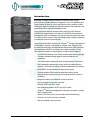
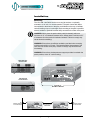
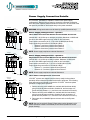
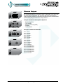
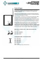
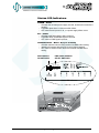
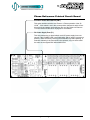
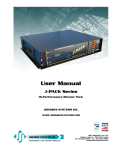
User Manual
JS-ICON 624 PACK
Portable Dimmer Pack
™
JOHNSON SYSTEMS INC.
Spring 2007
www.johnsonsystems.com
Table of Contents
Introduction.......................................................................................................3
Characteristics..................................................................................................4
JS-ICON™ 624 DMX
JS-ICON™ 624 CC
6 - 2.4kW Dimming Strip
Installation........................................................................................................5
Power Supply Connection Details....................................................................6
Dimmer Output.................................................................................................7
Control Input.....................................................................................................8
Status LED Indicators.......................................................................................9
System Configuration and Setup....................................................................10
Basic JS-ICON™ Troubleshooting...................................................................11
JS-ICON™ 624 ND
6 - 2.4kW Relay Strip
JS-ICON™ 624 PACK
6 - 2.4kW Portable Dimming Pack
Precision Demultiplexer Printed Circuit Board...............................................12
Phase Reference Printed Circuit Board.........................................................13
This manual is accurate at time of printing
and subject to revisions and technical
updates as required without prior notice.
Please visit
www.johnsonsystems.com
for applicable updates.
JS-ICON™ 624 ARCH
6 - 2.4kW Centralized Wall Mount
Architectural Dimming Rack
2
www.johnsonsystems.com
Introduction
JS-ICON™ portable dimmers deliver the ultimate value in high
performance portable dimming. Designed to set a new standard, this
rugged design is ideal for use in applications where multiple location
dimming is required. Simple to install and operate, these dimmers can
significantly lower electrical installation costs.
Large input wire capacity permits feeder power up to 60 Amps at
120/240 Volt single-phase or 40 Amps at 120/208 Volt three-phase!
Designed for ease of installation and service with removable top panel
for control section access. Future servicing of high voltage receptacles
or electronic controls is fast and easy.
Large high performance chokes and “MagLev®” thermal management
technology for superior cooling that is virtually silent. All electronics
are easily and remotely monitored with intuitive status LED indicators.
Optional wireless DMX 512 receiver and a high-resolution (16 bit)
fade make this dimmer a star performer in the portable category!
• Six 2400 Watt dimmers in a robust portable high density package.
• Compact stackable design permits system expansion as
necessary.
• Two-fered output receptacles allow for high density load control.
• Dims standard incandescent, quartz, and low-voltage fixtures.
• Superior 16-bit fade resolution provides unmatched performance.
• Both DMX 512 and individual analog control inputs.
• Optional wireless DMX receiver eliminates control wiring.
• Integral spring retracted, low profile carrying handle for ease of
portability.
• Magnetic breakers for maximum circuit protection.
• Over-heat and over-current protected.
• Dimmer SCR’s are 200% rated.
• Non-proprietary dimmer SCR’s are 200% rated.
•“MagLev®” thermal management technology for superior cooling
that is virtually silent.
• Status LED’s allow easy remote setup and troubleshooting.
• Optional 19” rack mount ears available.
• Industry leading 3 year warranty.
www.johnsonsystems.com
3
Characteristics
• Power Requirements: 120/208 VAC 3Ø 5 wire up to 40A. Max. rating
14.4kW. or 120/240 VAC 1Ø 4 wire up to 60A. Max. rating 14.4kW.
• Power Termination: Terminal block. 20A magnetic breaker
protection per circuit.
• Environment: Temperature Range: 32°F (0°C) to 104°F (40°C) ambient.
Humidity Range: 0% to 90% non-condensing.
• Dimmer Capacity and Load Type: 6 x 2.4kW standard incandescent,
quartz, and dimmable (SCR/Leading-Edge) electronic low-voltage
fixtures.
• Switch Type: 200% rated, non-proprietory SCR solid state relay.
• Rise Time: 300μs fully epoxy-encapsulated chokes are made from ultra
low audible noise core material.
• Physical: 16” W x 17” D x 7” H (40.6 cm x 43.2 cm x 17.8 cm).
• Weight: Approximately 35 lbs. (16 kg).
• Material: 0.125” aluminum.
• Finish: Textured black powdercoat.
Optional
Wireless Receiver
DMX and/or Analog
Control Input
20A Magnetic Breakers
Status LED Indicators
4
www.johnsonsystems.com
Installation
Mounting
The JS-ICON™ 624 PACK can be set on any flat surface, or optionally
mounted in a 19” rack, for normal operation. The pack comes with rubber
feet mounted to the bottom of the pack, and indents on the top, to facilitate
vertical stacking of up to 8 units high. Rack mounting of the pack is possible
with the addition of optional brackets easily mounted to the sides of the pack.
WARNING: Never place the packs side by side (horizontally) without a
minimum of 12” of clearance between them. Always leave a minimum of 6”
of clearance from the packs air intake and exhaust. Failure to comply may
cause thermal overheating.
WARNING: Ensure there is sufficient ventilation provided when mounting
multiple packs within a 19” rack. The internal ambient temperature of the
rack must not exceed 104F (40C). Failure to comply may cause thermal
overheating.
WARNING: Ensure there is adequate rear support provided to maintain the
packs position, when 19” rack mounting.
Right Side View
Cool Air Intake
Left Side View
Hot Air Exhaust
Optional 19”
Rack Mount Brackets
6”
Minimum Clearance
For Hot Air Exhaust
12”
Minimum Clearance
KEEP CLEAR
www.johnsonsystems.com
6”
Minimum Clearance
For Cool Air Intake
5
Power Supply Connection Details
The JS-ICON™ 624 PACK is capable of various 120V power supply
configurations. Remove the top panel to access the contractor termination
area, where the required power terminals are located. A 1.30” knockout in the
rear panel is provided for wire/conduit entry to the power terminals.
To Breakers 1 - 6
#12 AWG Wire
1 2
3 4
WARNING: Wiring termination must be done by qualified personnel only!
To Neutral
Terminal Block
5 6
To Phase
Reference PCB
#18 AWG Wire
Power Supply Configurations - Option 1:
Three-Phase with Internal Dimmer/Circuit Breaker Protection
A
B
C
120/208 VAC, 3Ø, 5-Wire up to 40 Amps per phase. Maximum 14.4kW total.
N
Incoming Phases
Incoming Neutral
Incoming Earth Ground
NOTE: Power supply requires an external disconnect.
To Breakers 1 - 6
#12 AWG Wire
123
456
To Neutral
Terminal Block
Power Supply Configurations - Option 2:
To Phase
Reference PCB
#18 AWG Wire
A
B
C
Incoming Earth Ground
To Breakers 1 - 6
#12 AWG Wire
56
To Neutral
Terminal Block
To Phase
Reference PCB
#18 AWG Wire
A
B
C
120/240 VAC, 1Ø, 4-Wire up to 60A per phase. Maximum 14.4kW total.
NOTE: Power supply requires an external disconnect.
Incoming Neutral
3 4
Single-Phase with Internal Dimmer/Circuit Breaker Protection
Use #2 to #12 AWG copper wire only, rated for 90°C minimum.
Torque power connections (A, C, N) to 5.0-5.6 NM (45-50 LB-IN).
Torque ground lug connection to 5.6 NM (50 LB-IN).
• Dimmers 1, 2, and 3 are powered from Phase A.
• Dimmers 4, 5, and 6 are powered from Phase C.
N
Incoming Phases
12
Use #2 to #12 AWG copper wire only, rated for 90°C minimum.
Torque power connections (A, B, C, N) to 5.0-5.6 NM (45-50 LB-IN).
Torque ground lug connection to 5.6 NM (50 LB-IN).
• Dimmers 1 and 2 are powered from Phase A.
• Dimmers 3 and 4 are powered from Phase B.
• Dimmers 5 and 6 are powered from Phase C.
N
Incoming Phases
Incoming Neutral
Incoming Earth Ground
Three-Phase to Single-Phase Conversion
JS-ICON™ systems are shipped from the factory ready for three-phase
operation unless otherwise specified at the time of purchase. The following
steps will need to be followed to convert the JS-ICON™ from three-phase
operation to single-phase operation.
1. Remove wire #3 (red #12AWG wire, marked with black heat-shrink)
going from the B power terminal to breaker #3, and reconnect to A
power terminal (dimmers 1, 2, and 3 are now connected to Phase A).
2. Remove wire #4 (red #12AWG wire, marked with blue heat-shrink)
going from the B power terminal to breaker #4 and reconnect to C
power terminal (dimmers 4, 5, and 6 are now connected to Phase C).
3. Reconnect the red #18AWG phase reference wire to the B power
terminal.
NOTE: Be sure to set the 3-Phase/1-Phase select switch (located on the
Phase Reference Printed Circuit Board) to the correct position to ensure
proper dimming.
6
www.johnsonsystems.com
Dimmer Output
Bates (Stage Pin)
Six (6) 2400 Watt dimmers (maximum rating 14,400 Watts at 120 VAC) with
two-fered output receptacles. The JS-ICON™ 624 PACK is designed for
high performance dimming of standard incandescent, quartz, and dimmable
(SCR/Leading-Edge) electronic low-voltage fixtures.
Output Connector/Receptacle Options
TLG (L520R)
• Bates (Stage Pin)
• TLG (L520R)
• Edison (U-Ground) (520R)
•Socapex
• Terminal Block
Socapex Connection Details
Edison (U-Ground) (520R)
Socapex
Pin 1 = Line 1
Pin 2 = Neutral 1
Pin 3 = Line 2
Pin 4 = Neutral 2
Pin 5 = Line 3
Pin 6 = Neutral 3
Pin 7 = Line 4
Pin 8 = Neutral 4
Pin 9 = Line 5
Pin 10 = Neutral 5
Pin 11 = Line 6
Pin 12 = Neutral 6
Pin 13 = Earth Ground 1
Pin 14 = Earth Ground 2
Pin 15 = Earth Ground 3
Pin 16 = Earth Ground 4
Pin 17 = Earth Ground 5
Pin 18 = Earth Ground 6
Pin 19 = Not Used
Terminal Block
www.johnsonsystems.com
7
Control Input
The JS-ICON™ 624 DMX accepts both DMX 512-A protocol and analog
0-10VDC. These control inputs are configured for HTP (highest takes
precedence) operation.
DMX Data Input and DMX Data Thru is connected via external 5-pin XLR
connectors located on the front panel of the pack, or via internal breakaway
type connectors (see diagram on page 9).
POWER/DMX IN
ID
RF OUT
RADIO
CHANNEL
RESET
Wireless DMX Option
Analog 0-10VDC is connected via an external 9-Pin D-Subminiature (DB9)
connector located on the front panel of the pack. The DB9 facilitates
connection of a simple analog control station (Johnson Systems Inc. Part #
CS-2903-6) where local control is required. Analog may also be connected
internally via internal breakaway type connectors (see diagram on page 9).
Wireless DMX (WDS) is optional for all JS-ICON™ Series dimming models.
The WDS (Wireless Dimming System) from City Theatrical has been
selected for its reliability and ease of use. The “WDS Kit” - supplied only by
Johnson Systems - can be easily adapted to all JS-ICON™ products. It comes
complete with a wiring harness and mounting hardware, and installs quickly.
For more information, see the JS-ICON™ Wireless DMX User Manual.
DMX Input and Thru 5-Pin / XLR Connection Details
Pin 1 = Common
Pin 2 = Data 1– (Input/Thru)
Pin 3 = Data 1+ (Input/Thru)
Pin 4 = Data 2– (Thru)
Pin 5 = Data 2+ (Thru)
Analog Input DB9 / Connection Details
Pin 1 = Analog Input 1
Pin 2 = Analog Input 2
Pin 3 = Analog Input 3
Pin 4 = Analog Input 4
Pin 5 = Analog Input 5
Pin 6 = Analog Input 6
Pin 7 = Common
Pin 8 = Common
Pin 9 = +12VDC Power Supply (200mA Maximum)
8
www.johnsonsystems.com
Status LED Indicators
POWER = Green
• ON when the on-board power supply is active, and the microcontroller is
running.
• FLASHES when there is a microcontroller failure.
• OFF when Phase-A power is off, or a power supply failure occurs.
RX
•
•
•
= Amber
ON when valid DMX signal is being received.
FLASHES when invalid DMX signal is received.
OFF when no DMX signal is present.
CONTROL LEVEL = Blue x 6 (1 per channel)
• ON when dimmer control is being received via DMX and/or analog.
• Intensity will increase with the level of control being received.
• OFF when no dimmer control levels are received via DMX and/or
analog.
MODE SELECT
DIP SWITCHES
DMX START ADDRESS
SELECT SWITCHES
Status LED Indicators
www.johnsonsystems.com
9
System Configuration and Setup
1. SETTING THE DMX START ADDRESS
Select the desired DMX start address for the JS-ICON™ via the three
rotary DMX START ADDRESS SELECT SWITCHES located on the front
of the control box (as pictured on the previous page). This start address
is selectable in single channel increments. All dimmers within a given JSICON™ will numerically/incrementally follow the selected start address for a
total of six channels. Therefore, if the DMX start address is 001, then the JSICON™’s dimmers will be addressed as 001, 002, 003, 004, 005, and 006.
2. CONFIGURE THE MODE SELECT DIP SWITCHES
DMX TERM: MODE SELECT DIP SWITCH #1
Setting this switch to the “ON” position activates the DMX “end-of-line”
termination. In a DMX network, the device that appears last in the daisy
chain of devices is designated as the “end of line” and must be terminated
properly to maintain the integrity of DMX data transmission. It is important
that only the “end-of-line” device is terminated.
DMX HOLD: MODE SELECT DIP SWITCH #3
Setting this switch to the “ON” position activates the DMX Hold feature.
With the loss of DMX, the JS-ICON™ will “hold” the last DMX data levels
received for 2 minutes. Setting this switch to the “OFF” position disables this
feature, and will “hold” the last DMX data levels received for 2 seconds.
DIMMER TEST: MODE SELECT DIP SWITCH #4
Setting this switch to the “ON” position activates the Dimmer Test feature.
This feature enables the selection of one dimmer, or all dimmers, to be
turned full on. Selection of the dimmer is via the rotary DMX START
ADDRESS X1 switch. Setting the DMX address to “001” through “006” turns
the corresponding dimmer output to full. Setting the DMX address to “007”
turns all dimmers outputs to full on. Setting this switch to the “OFF” position
will permit normal operation via DMX and/or analog control.
CURVE SELECT: MODE SELECT DIP SWITCH #5 AND #6
These two DIP switches allow for modification of the dimmer output curve.
Below is a selection chart including the four possible dimmer output curves.
10
DIP SWITCH #5
DIP SWITCH #6
DIMMER CURVE
OFF
OFF
Square Law (Factory Default)
OFF
ON
Direct Drive
ON
OFF
Channel 1 functions as non-dim with a 50% threshold trigger.
Channels 2 - 6 are assigned as Square Law.
ON
ON
All dimmers function as non-dims with a 50% threshold trigger.
www.johnsonsystems.com
Basic JS-ICON™ Troubleshooting
Fault/Complaint
Status LED Indicators
Possible Reason/Fix
No output (all circuits).
Power LED Off.
No power to system. Check main breaker.
No output (all circuits).
Power LED Flashes.
Microcontroller failure. Contact factory.
No output (all circuits).
Power LED On, RX LED Off.
No DMX signal is present.
No output (all circuits).
Power LED On, RX LED Flashes.
Invalid DMX signal is received.
No output (all circuits).
Power LED On, RX LED On,
Control Level LED’s Off.
Verify correct DMX Start Address is set.
No output (all circuits).
All LED’s On.
Dimmer circuit breakers off or tripped. Check
breakers.
No output (one or
more circuits).
All LED’s On.
Dimmer circuit breaker(s) off or tripped.
Check breakers.
Internal hardware failure. Contact factory.
Burnt out lamp(s) or defective fixture.
Replace with known good fixture and lamp.
Light(s) do not dim,
on/off only.
All LED’s On.
JS-ICON™ configured as a “non-dim”. Check
DIP switch settings.
JS-ICON™ incorrectly wired. Verify contractor
wiring and power type (1-phase or 3-phase).
Confirm model number power requirement.
Contact factory.
Lights on circuits 3
and 4 do not dim,
on/off only.
All LED’s On.
JS-ICON™ incorrectly wired. Verify contractor
wiring and power type (1-phase or 3-phase).
Verify 1-phase/3-phase switch is set for the
correct incoming power supply type.
Light(s) will not dim
out completely.
All LED’s On.
Control levels present on DMX. Check DMX.
Lights stuck on.
Power LED On, RX LED On,
Control Level LED’s Off.
Defective SSR. Replace SSR power pack.
Lights off, no control.
Power LED On, RX LED On,
Control Level LED’s On.
Dimmer circuit breaker(s) off or tripped.
Check breakers.
Analog signal present. Remove analog
signal source and re-check.
Burnt out lamp(s) or defective fixture.
Replace with known good fixture or lamp.
Defective SSR. Replace SSR power pack.
Lights flickering.
Power LED On, RX LED On,
Control Level LED’s On or Off.
Defective SSR. Replace SSR power pack.
Lights flickering.
Power LED On, RX LED On,
Control Level LED’s flickering
between On and Off.
Noise on DMX line. Verify DMX termination
is correct for the system.
Noise on analog inputs. Disconnect analog
inputs and re-check.
Defective SSR. Replace SSR power pack.
WARNING: Ensure all power is disconnected prior to servicing! All
servicing of this product should be performed by authorized personnel only!
Unauthorized service may void the warranty!
www.johnsonsystems.com
11
Precision Demultiplexer Printed Circuit Board
DMX INPUT/THRU Connection (J11)
This internal DMX connection may be used alternatively to the external
5-Pin XLR connectors. It is also the location used for connection of the
wireless DMX receiver option.
+5VDC and +15VDC Power Supply Output Connection (J8)
This connection supplies power for external devices. The +5VDC supply
is normally used for powering the wireless DMX receiver option, while the
+15VDC supply may be used for other external devices. External devices
should not exceed the maximum combined current draw of 200mA.
0-10VDC Analog Inputs with +12VDC Power Supply (J9)
This connection is the location to land the 0-10VDC analog inputs.
“ANA1” through “ANA6” controls dimmer 1 through dimmer 6 respectively.
This connection also provides a +12VDC power supply normally used for
powering external analog devices. External devices should not exceed the
maximum combined current draw of 200mA.
12
www.johnsonsystems.com
Phase Reference Printed Circuit Board
3-Phase/1-Phase Select Switch (SW1)
This switch enables selection of 3-Phase or 1-Phase operation of the JSICON™ . If this switch is not in the correct position, dimmers 3 and 4 will not
dim correctly and appear as though they are non-dim. Refer to 3-Phase to
1-Phase conversion directions on page 6 for more details.
DC Power Supply Fuse (F1)
This fuse protects the on-board switch mode DC power supply from overcurrent. If the “POWER” LED is not illuminating, and AC power is present on
phase A, check the fuse by removing the fuse holder cap and inspecting, or
measure continuity. If the fuse needs to be replaced, only use a fuse rated
the same as the original GDC 250mA 250V fuse.
www.johnsonsystems.com
13
Notes
14
www.johnsonsystems.com
Notes
www.johnsonsystems.com
15
User Manual
JS-ICON™ Series Dimmers
Spring 2007
www.johnsonsystems.com