1
Canopy™ Access Point
Cluster and Gen II Cluster
Management Module
USER MANUAL
AP_CMM2-UM-en
Issue 4
December 2003
© 2003 Motorola, Inc. All rights reserved. Printed in the U.S.A.
NOTICES
Important Note on Modifications
Intentional or unintentional changes or modifications to the equipment must not be made unless under the express consent of the party
responsible for compliance. Any such modifications could void the user’s authority to operate the equipment and will void the
manufacturer’s warranty.
U.S. Federal Communication Commision (FCC) and Industry Canada (IC) Notification
This device complies with part 15 of the U. S. FCC Rules and Regulations and with RSS-210 of Industry Canada. Operation is subject
to the following two conditions: (1) This device may not cause harmful interference, and (2) This device must accept any interference
received, including interference that may cause undesired operation. In Canada, users should be cautioned to take note that high power
radars are allocated as primary users (meaning they have priority) of 5250 – 5350 MHz and 5650 – 5850 MHz and these radars could
cause interference and/or damage to license-exempt local area networks (LELAN).
This equipment has been tested and found to comply with the limits for a Class B digital device, pursuant to Part 15 of the U.S. FCC
Rules and with RSS-210 of Industry Canada. These limits are designed to provide reasonable protection against harmful interference in
a residential installation. This equipment generates, uses, and can radiate radio-frequency energy and, if not installed and used in
accordance with these instructions, may cause harmful interference to radio communications. If this equipment does cause harmful
interference to radio or television reception, which can be determined by turning the equipment on and off, the user is encouraged to
correct the interference by one or more of the following measures:
Increase the separation between the affected equipment and the unit;
Connect the affected equipment to a power outlet on a different circuit from that which the receiver is connected to;
Consult the dealer and/or experienced radio/TV technician for help.
FCC IDs and Industry Canada Certification Numbers are listed in the following table:
Reflector
FCC ID
Industry Canada
Maximum
Transmitter
Cert Number
Power
SM AP BH
ISM 2400-2483.5 MHz
340mW
Allowed on SM and BH
ABZ89FC5808
Applied for
SM AP BH
U-NII 5250-5350 MHz
200mW
Not Allowed
ABZ89FC3789
109W-5200
SM AP BH
U-NII 5725-5825 MHz
200mW
Allowed on SM and BH
ABZ89FC4816
109W-5700
SM AP BH
ISM 5725-5850 MHz
200mW
Allowed on SM and BH
ABZ89FC5804
109W-5700
The term “IC:” before the radio certification number only signifies that Industry Canada technical specifications were met.
Module
Types
Frequency Band Range
European Community Notification
Notification of Intended Purpose of Product Uses
This product is a two-way radio transceiver suitable for use in Broadband RLAN systems. It uses operating frequencies which are not
harmonized through the EC. All licenses must be obtained before using the product in any EC country.
Declaration of conformity:
Motorola declares the GHz radio types listed below comply with the essential requirements and other relevant provisions of
Directive1999/5/EC.
Relevant Specification
EN 301 893 or similar - radio spectrum
EN301489-17 - EMC
EN60950 - safety
Product Details for Products Tested for Compliance with Relevant EC Directives
Module
Type
Frequency
Band Range
Maximum
Transmitter
Power
Effective Isotropic
Radiated Power
(EIRP)
Modulation Type
Operating Channels
Access Point
5.725 to 5.825
GHz
200mW RMS
1 Watt EIRP
High Index 2-level
FSK
5745 to 5805 MHz in
5 MHz increments
Subscriber
Module
Subscriber
Module with
Reflector
Backhaul
5.725 to 5.825
GHz
5.725 to 5.825
GHz
200mW RMS
1 Watt EIRP
63 Watts EIRP
5745 to 5805 MHz in
5 MHz increments
5745 to 5805 MHz in
5 MHz increments
20 MHz
200mW RMS
High Index 2-level
FSK
High Index 2-level
FSK
5.725 to 5.825
GHz
200mW RMS
1 Watt EIRP
High Index 2-level
or 4-level FSK
5745 to 5805 MHz in
5 MHz increments
20 MHz
AP_CMM2 User Manual Issue 4 Draft
Nonoverlapping
Channel
Spacing
20 MHz
20 MHz
Page 2 of 50
Backhaul with
Reflector
5.725 to 5.825
GHz
200mW RMS
63 Watts EIRP
High Index 2-level
or 4-level FSK
5745 to 5805 MHz in
5 MHz increments
20 MHz
Canopy can be configured to operate at a range of frequencies, but at this time, only channels from 5745 MHz through 5805 MHz of the
5.7 GHz product have been tested for compliance with relevant EC directives. Before configuring equipment to operate outside this
range, please check with your regulator.
Exposure Note
A Canopy module must be installed to provide a separation distance of at least 20 cm (7.9 in) from all persons. When adding the Canopy
reflector dish, the reflector dish must be installed to provide a separation distance of at least 1.5m (59.1 in) from all persons. When so
installed, the module’s RF field is within Health Canada limits for the general population; consult Safety Code 6, obtainable from Health
Canada’s website http://www.hc-sc.gc.ca/rpb.
In both configurations the maximum RMS power does not exceed 340mW.
The applicable power density exposure limit is 10 Watt/m2, according to the FCC OET Bulletin 65, the ICNIRP guidelines, and the
Health Canada Safety Code 6. The corresponding compliance distances referenced above have been determined by assuming worst-case
scenarios. The peak power density (S) in the far-field of a radio-frequency source with rms transmit power P and antenna gain G at a
distance d is
S=
P ⋅G
4π d 2
In the case of the Canopy module without reflector, the gain is 8 dBi (a factor of 6.3), so the peak power density equals the exposure
limit at a distance of 13 cm for 2.4 GHz product and 10 cm for 5.2 and 5.7 GHz product. A power compliance margin of over 2 is
artificially introduced by setting the distance to a consistent 20 cm across all modules, giving a power compliance margin of x2.4 for 2.4
GHz modules and x4 for 5.2 and 5.7 GHz modules.
In the case of the Canopy module with reflector, the gain depends on frequency and ranges from 19 dBi (a factor of 80) for 2.4 GHz
modules to 26 dBi (a factor of 400) for 5.7 GHz modules, so the peak power density equals the exposure limit at a distance of 46 to 80
cm. A power compliance margin is artificially introduced by defining a consistent compliance distance of 1.5 m across all modules,
giving a power compliance margin of x10 for 2.4 GHz modules and x3.5 for 5.7 GHz modules. The compliance distance is greatly
overestimated in this case because the far-field equation neglects the physical dimension of the antenna, which is modeled as a pointsource.
Software License Terms and Conditions
ONLY OPEN THE PACKAGE, OR USE THE SOFTWARE AND RELATED PRODUCT IF YOU ACCEPT THE TERMS OF THIS
LICENSE. BY BREAKING THE SEAL ON THIS DISK KIT / CDROM, OR IF YOU USE THE SOFTWARE OR RELATED
PRODUCT, YOU ACCEPT THE TERMS OF THIS LICENSE AGREEMENT. IF YOU DO NOT AGREE TO THESE TERMS, DO
NOT USE THE SOFTWARE OR RELATED PRODUCT; INSTEAD, RETURN THE SOFTWARE TO PLACE OF PURCHASE FOR
A FULL REFUND. THE FOLLOWING AGREEMENT IS A LEGAL AGREEMENT BETWEEN YOU (EITHER AN INDIVIDUAL
OR ENTITY), AND MOTOROLA, INC. (FOR ITSELF AND ITS LICENSORS). THE RIGHT TO USE THIS PRODUCT IS
LICENSED ONLY ON THE CONDITION THAT YOU AGREE TO THE FOLLOWING TERMS.
Now, therefore, in consideration of the promises and mutual obligations contained herein, and for other good and valuable consideration,
the receipt and sufficiency of which are hereby mutually acknowledged, you and Motorola agree as follows:
Grant of License. Subject to the following terms and conditions, Motorola, Inc., grants to you a personal, revocable, non-assignable,
non-transferable, non-exclusive and limited license to use on a single piece of equipment only one copy of the software contained on this
disk (which may have been pre-loaded on the equipment)(Software). You may make two copies of the Software, but only for backup,
archival, or disaster recovery purposes. On any copy you make of the Software, you must reproduce and include the copyright and other
proprietary rights notice contained on the copy we have furnished you of the Software.
Ownership. Motorola (or its supplier) retains all title, ownership and intellectual property rights to the Software and any copies,
including translations, compilations, derivative works (including images) partial copies and portions of updated works. The Software is
Motorola’s (or its supplier's) confidential proprietary information. This Software License Agreement does not convey to you any interest
in or to the Software, but only a limited right of use. You agree not to disclose it or make it available to anyone without Motorola’s
written authorization. You will exercise no less than reasonable care to protect the Software from unauthorized disclosure. You agree not
to disassemble, decompile or reverse engineer, or create derivative works of the Software, except and only to the extent that such activity
is expressly permitted by applicable law.
Termination. This License is effective until terminated. This License will terminate immediately without notice from Motorola or
judicial resolution if you fail to comply with any provision of this License. Upon such termination you must destroy the Software, all
accompanying written materials and all copies thereof, and the sections entitled Limited Warranty, Limitation of Remedies and
Damages, and General will survive any termination.
Limited Warranty. Motorola warrants for a period of ninety (90) days from Motorola’s or its customer’s shipment of the Software to
you that (i) the disk(s) on which the Software is recorded will be free from defects in materials and workmanship under normal use and
(ii) the Software, under normal use, will perform substantially in accordance with Motorola’s published specifications for that release
level of the Software. The written materials are provided "AS IS" and without warranty of any kind. Motorola's entire liability and your
AP_CMM2 User Manual Issue 4 Draft
Page 3 of 50
sole and exclusive remedy for any breach of the foregoing limited warranty will be, at Motorola's option, replacement of the disk(s),
provision of downloadable patch or replacement code, or refund of the unused portion of your bargained for contractual benefit up to the
amount paid for this Software License.
THIS LIMITED WARRANTY IS THE ONLY WARRANTY PROVIDED BY MOTOROLA, AND MOTOROLA AND ITS
LICENSORS EXPRESSLY DISCLAIM ALL OTHER WARRANTIES, EITHER EXPRESS OF IMPLIED, INCLUDING BUT NOT
LIMITED TO IMPLIED WARRANTIES OF MERCHANTABILITY AND FITNESS FOR A PARTICULAR PURPOSE AND
NONINFRINGEMENT. MOTOROLA DOES NOT WARRANT THAT THE OPERATION OF THE SOFTWARE WILL BE
UNINTERRUPTED OR ERROR-FREE, OR THAT DEFECTS IN THE SOFTWARE WILL BE CORRECTED. NO ORAL OR
WRITTEN REPRESENTATIONS MADE BY MOTOROLA OR AN AGENT THEREOF SHALL CREATE A WARRANTY OR IN
ANY WAY INCREASE THE SCOPE OF THIS WARRANTY. MOTOROLA DOES NOT WARRANT ANY SOFTWARE THAT
HAS BEEN OPERATED IN EXCESS OF SPECIFICATIONS, DAMAGED, MISUSED, NEGLECTED, OR IMPROPERLY
INSTALLED. BECAUSE SOME JURISDICTIONS DO NOT ALLOW THE EXCLUSION OR LIMITATION OF IMPLIED
WARRANTIES, THE ABOVE LIMITATIONS MAY NOT APPLY TO YOU.
Limitation of Remedies and Damages. Regardless of whether any remedy set forth herein fails of its essential purpose, IN NO EVENT
SHALL MOTOROLA OR ANY OF THE LICENSORS, DIRECTORS, OFFICERS, EMPLOYEES OR AFFILIATES OF THE
FOREGOING BE LIABLE TO YOU FOR ANY CONSEQUENTIAL, INCIDENTAL, INDIRECT, SPECIAL OR SIMILAR
DAMAGES WHATSOEVER (including, without limitation, damages for loss of business profits, business interruption, loss of business
information and the like), whether foreseeable or unforeseeable, arising out of the use or inability to use the Software or accompanying
written materials, regardless of the basis of the claim and even if Motorola or a Motorola representative has been advised of the
possibility of such damage. Motorola's liability to you for direct damages for any cause whatsoever, regardless of the basis of the form
of the action, will be limited to the price paid for the Software that caused the damages. THIS LIMITATION WILL NOT APPLY IN
CASE OF PERSONAL INJURY ONLY WHERE AND TO THE EXTENT THAT APPLICABLE LAW REQUIRES SUCH
LIABILITY. BECAUSE SOME JURISDICTIONS DO NOT ALLOW THE EXCLUSION OR LIMITATION OF LIABILITY FOR
CONSEQUENTIAL OR INCIDENTAL DAMAGES, THE ABOVE LIMITATION MAY NOT APPLY TO YOU.
Maintenance and Support. Motorola shall not be responsible for maintenance or support of the software. By accepting the license
granted under this agreement, you agree that Motorola will be under no obligation to provide any support, maintenance or service in
connection with the Software or any application developed by you. Any maintenance and support of the Related Product will be
provided under the terms of the agreement for the Related Product.
Transfer. In the case of software designed to operate on Motorola equipment, you may not transfer the Software to another party except:
(1) if you are an end-user, when you are transferring the Software together with the Motorola equipment on which it operates; or 2) if
you are a Motorola licensed distributor, when you are transferring the Software either together with such Motorola equipment or are
transferring the Software as a licensed duly paid for upgrade, update, patch, new release, enhancement or replacement of a prior version
of the Software. If you are a Motorola licensed distributor, when you are transferring the Software as permitted herein, you agree to
transfer the Software with a license agreement having terms and conditions no less restrictive than those contained herein. You may
transfer all other Software, not otherwise having an agreed restriction on transfer, to another party. However, all such transfers of
Software are strictly subject to the conditions precedent that the other party agrees to accept the terms and conditions of this License, and
you destroy any copy of the Software you do not transfer to that party. You may not sublicense or otherwise transfer, rent or lease the
Software without our written consent. You may not transfer the Software in violation of any laws, regulations, export controls or
economic sanctions imposed by the U.S. Government.
Right to Audit. Motorola shall have the right to audit annually, upon reasonable advance notice and during normal business hours, your
records and accounts to determine compliance with the terms of this Agreement.
Export Controls. You specifically acknowledge that the software may be subject to United States and other country export control laws.
You shall comply strictly with all requirements of all applicable export control laws and regulations with respect to all such software and
materials.
U.S. Government Users. If you are a U.S. Government user, then the Software is provided with "RESTRICTED RIGHTS" as set forth
in subparagraphs (c)(1) and (2) of the Commercial Computer Software-Restricted Rights clause at FAR 52 227-19 or subparagraph
(c)(1)(ii) of the Rights in Technical Data and Computer Software clause at DFARS 252.227-7013, as applicable.
Disputes. You and Motorola hereby agree that any dispute, controversy or claim, except for any dispute, controversy or claim involving
intellectual property, prior to initiation of any formal legal process, will be submitted for non-binding mediation, prior to initiation of
any formal legal process. Cost of mediation will be shared equally. Nothing in this Section will prevent either party from resorting to
judicial proceedings, if (i) good faith efforts to resolve the dispute under these procedures have been unsuccessful, (ii) the dispute, claim
or controversy involves intellectual property, or (iii) interim relief from a court is necessary to prevent serious and irreparable injury to
that party or to others.
General. Illinois law governs this license. The terms of this license are supplemental to any written agreement executed by both parties
regarding this subject and the Software Motorola is to license you under it, and supersedes all previous oral or written communications
between us regarding the subject except for such executed agreement. It may not be modified or waived except in writing and signed by
an officer or other authorized representative of each party. If any provision is held invalid, all other provisions shall remain valid, unless
such invalidity would frustrate the purpose of our agreement. The failure of either party to enforce any rights granted hereunder or to
take action against the other party in the event of any breach hereunder shall not be deemed a waiver by that party as to subsequent
enforcement of rights or subsequent action in the event of future breaches.
AP_CMM2 User Manual Issue 4 Draft
Page 4 of 50
Hardware Warranty in U.S.
Motorola U.S. offers a warranty covering a period of one year from the date of purchase by the customer. If a product is found defective
during the warranty period, Motorola will repair or replace the product with the same or a similar model, which may be a reconditioned
unit, without charge for parts or labor.
IN NO EVENT SHALL MOTOROLA BE LIABLE TO YOU OR ANY OTHER PARTY FOR ANY DIRECT, INDIRECT,
GENERAL, SPECIAL, INCIDENTAL, CONSEQUENTIAL, EXEMPLARY OR OTHER DAMAGE ARISING OUT OF THE USE
OR INABILITY TO USE THE PRODUCT (INCLUDING, WITHOUT LIMITATION, DAMAGES FOR LOSS OF BUSINESS
PROFITS, BUSINESS INTERRUPTION, LOSS OF BUSINESS INFORMATION OR ANY OTHER PECUNIARY LOSS, OR FROM
ANY BREACH OF WARRANTY, EVEN IF MOTOROLA HAS BEEN ADVISED OF THE POSSIBILITY OF SUCH DAMAGES.
(Some states do not allow the exclusion or limitation of incidental or consequential damages, so the above exclusion or limitation may
not apply to you.) IN NO CASE SHALL MOTOROLA’S LIABILITY EXCEED THE AMOUNT YOU PAID FOR THE PRODUCT.
Trademarks, Product Names, and Service Names
MOTOROLA, the stylized M Logo and all other trademarks indicated as such herein are trademarks of Motorola, Inc. ® Reg. U.S. Pat
& Tm. Office. Canopy is a trademark of Motorola, Inc. All other product or service names are the property of their respective owners.
Motorola, Inc
http://www.motorola.com/canopy
AP_CMM2 User Manual Issue 4 Draft
Page 5 of 50
TABLE OF CONTENTS
GETTING STARTED ........................................................................................... 11
Welcome ............................................................................................................................................. 11
Intended Use....................................................................................................................................... 11
Document Change History ................................................................................................................. 11
PRODUCT DESCRIPTION .................................................................................. 11
Operation ............................................................................................................................................ 12
Configuration....................................................................................................................................... 12
BACKGROUND INFORMATION on NETWORKING.......................................... 15
SYSTEM OVERVIEW AND SITE PLANNING ..................................................... 16
Site Selection Criteria ......................................................................................................................... 17
General Considerations...................................................................................................................... 18
Channel Plans..................................................................................................................................... 19
2.4 GHz Recommended Frequencies............................................................................................ 19
5.2 GHz Recommended Frequencies............................................................................................ 19
5.7 GHz Recommended Frequencies............................................................................................ 19
Single Access Point Module........................................................................................................... 20
Single Access Point Cluster ........................................................................................................... 20
Multiple Access Points Clusters ..................................................................................................... 20
Networking Information ...................................................................................................................... 22
Lightning Protection............................................................................................................................ 22
Electrical Requirements ..................................................................................................................... 22
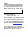
ADVANCED FEATURES..................................................................................... 23
Security - DES Encryption.................................................................................................................. 23
Security - AES Encryption.................................................................................................................. 23
Bandwidth Management..................................................................................................................... 24
High Priority Bandwith ........................................................................................................................ 24
Branding.............................................................................................................................................. 25
SNMP .................................................................................................................................................. 26
INSTALLATION ................................................................................................... 27
Unpack the Canopy Products ............................................................................................................ 27
Configuration of the Access Point Modules....................................................................................... 27
Configuration of the Cluster Management Module ........................................................................... 28
Installation of the Equipment.............................................................................................................. 28
Verification .......................................................................................................................................... 31
CABLING ............................................................................................................. 32
THE INTERFACE SCREENS .............................................................................. 34
Quick Start .......................................................................................................................................... 34
Status Page......................................................................................................................................... 35
Configuration....................................................................................................................................... 37
Canopy Default Plug........................................................................................................................... 41
Event Log ............................................................................................................................................ 42
LUID Select......................................................................................................................................... 42
Link Test.............................................................................................................................................. 43
AP_CMM2 User Manual Issue 4 Draft
Page 6 of 50
Time & Date ........................................................................................................................................ 43
Sessions.............................................................................................................................................. 44
GPS Status ......................................................................................................................................... 46
Ethernet Stats ..................................................................................................................................... 46
Expanded Stats................................................................................................................................... 47
ACCESSORIES ................................................................................................... 48
APPENDIX ........................................................................................................... 49
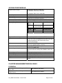
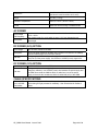
SPECIFICATIONS ............................................................................................... 49
Access Point Module .......................................................................................................................... 50
Cluster Management Module Gen II.................................................................................................. 50
Physical ............................................................................................................................................... 50
AC Power ............................................................................................................................................ 51
DC Power (24V) Option...................................................................................................................... 51
DC Power (12V) Option...................................................................................................................... 51
Cable Specifications ........................................................................................................................... 51
TABLE OF FIGURES
Figure 1: Canopy Access Point Module ................................................................................................ 12
Figure 2: Front view of Cluster Management Module, Installed........................................................... 13
Figure 3: Bottom view of Cluster Management Module, Installed........................................................ 14
Figure 4: System Wiring Diagram.......................................................................................................... 17
Figure 5: Fresnel Zone........................................................................................................................... 18
Figure 6: Laying out multiple Access Point clusters ............................................................................. 21
Figure 7: Location of 115/230 V Switch................................................................................................. 28
Figure 8: Detail of pole mounting........................................................................................................... 29
Figure 9: Detail of GPS antenna mounting ........................................................................................... 30
Figure 10: Port indicator LED on Ethernet switch................................................................................. 31
Figure 11: Quick Start web page ........................................................................................................... 34
Figure 12: Status web page ................................................................................................................... 35
Figure 13: Configuration web page ....................................................................................................... 37
Figure 14: LUID Select web page.......................................................................................................... 42
Figure 15: Link Test web page .............................................................................................................. 43
WELCOME
Thank you for your purchase of a Motorola Canopy Access Point cluster and/or Cluster
Management Module. This new technology is the latest innovation in high speed wireless
networking. Some of the Canopy system features are:
• Network speeds of 10/100 BaseT
• Small compact design
• No special set up on your PC.
INTENDED USE
This manual is intended to be used with Canopy software release version 3.x or greater. The
intended audience for this manual is system operators and equipment installers.
DOCUMENT CHANGE HISTORY
AP_CMM2 User Manual Issue 4 Draft
Page 7 of 50
New in Issue 4:
• Modules operating in the 2.4 GHz ISM band are described
• One year warranty
New in Issue 3:
• AES product described, along with DES product
• 5.7 GHz ISM supports 6 channels (up from 4 with 5.7 GHz U-NII)
• 5.7 GHz ISM frequencies approved for use in Canada, as well as US
• Maximum power used by an Access Point module increases to 8.4 watts
• Shielded cables strongly recommended for all infrastructure cabling connecting APs,
BHs, and CMM
• MAC addresses of older non-autosensing modules are listed (non-autosensing
modules require correct choice of straight-thru vs crossover cables)
New in Issue 2:
• Updated Notices section including European Community Notification, RF
Exposure Note, and Software License Terms and Conditions.
• Measurement units internationalized with metric as well as English units
• Updates for new hardware features:
- Currently shipping modules now auto-sense the Ethernet termination –
either a straight-thru or crossover RJ-45 cable can be used to connect to
either a network interface card or hub, switch, or router.
- The currently shipping CMM has additional cable openings to ease the use
of shielded cable.
• References to the Canopy Bandwidth and Authentication Manager (BAM), and the
additional bandwidth and security features it offers beyond the features provided
by an Access Point with no BAM in the network.
• Specifications changed to reflect expanded lower temperature limit of -40°F (40°C) for all equipment.
• Specifications clarified and edited for CE Listing for European Community
PRODUCT DESCRIPTION
OPERATION
The Canopy Access Point module’s simple design allows for deployment ease. The Canopy
Cluster Management Module provides everything necessary to make a system of single or multiple
Canopy Access Point modules operational. It provides power, GPS synchronization and Ethernet
connectivity.
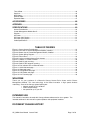
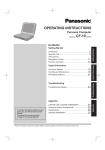
CONFIGURATION
Access Point Module
As shown below, the base cover of the module snaps off to expose the Ethernet and GPS sync
connectors as well as diagnostic LEDs. The base cover is released by depressing a lever on the
back side of the base cover.
AP_CMM2 User Manual Issue 4 Draft
Page 8 of 48
Canopy AP
RJ45
Connector
RJ11
Connector
Connection
LEDs
Base Cover
Base Cover
Ethernet
Cable
Base Cover
Release
Lever
Ethernet
Cable
Figure 1: Canopy Access Point Module
The diagnostic LEDs report information about the current status of the Access Point module. The
following descriptions explain the function of each LED from left to right.
LNK: The link LED displays the status of the Ethernet link to the Canopy module. The LED will be
constantly lit if there is an Ethernet link present. The LED is colored green.
ACT/4: The activity LED displays the status of any data activity on the Ethernet link. The LED will
flash (at no particular speed) when data is being transferred on the Ethernet link. The LED is
colored orange.
GPS/3: The GPS LED displays the status of the sync pulse and is lit constantly when the pulse is
being received. The LED is red.
SES/2: The session LED is not used on the Access Point module. The LED is green.
SYN/1: The sync LED displays sync status. In short, this LED will lit all the time on an Access
Point module. The LED is orange.
PWR: The power LED displays the status of power to the module. The LED will be constantly lit if
power is applied correctly. The LED is red.
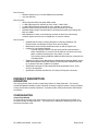
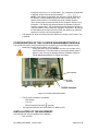
Cluster Management Module generation II
There are four major assemblies contained inside the Cluster Management Module. They are the
Ethernet switch, the power transformer, the interconnect board and the GPS receiver.
AP_CMM2 User Manual Issue 4 Draft
Page 9 of 48
Ethernet switch
Extra fuse
GPS
sync
Ethernet
DC power connectors
AC power connectors
Figure 2: Front view of Cluster Management Module, Installed
AP_CMM2 User Manual Issue 4 Draft
Page 10 of 48
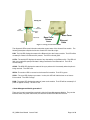
Earlier units had four openings on the bottom of the Cluster Management Module as shown in the
following figure. Currently shipping units have two additional Ethernet cable and GPS sync cable
openings, to allow use of thicker, shielded cables.
N-connector to GPS antenna
GPS sync cables
Network feed
Power feed
Ethernet cables
Figure 3: Bottom view of Cluster Management Module, Installed
Mains AC power feed should be either 12 AWG or 14 AWG (4 mm2 or 2.5 mm2) wire, with the
thicker gauge recommended for longer power runs.
AP_CMM2 User Manual Issue 4 Draft
Page 11 of 48
BACKGROUND INFORMATION ON NETWORKING
Computers are assigned IP addresses by network operators, which have two methods available,
static or dynamic IP addressing. The user of this document will need to understand how IP
addressing is done at their particular location.
All Canopy radio products (Subscriber Modules, Access Point Modules, and Backhaul Modules)
have the default IP address of 169.254.1.1. For a computer to talk to Canopy, as it comes from the
factory, either of the following conditions must be met:
•
•
If the computer is not configured for DHCP, then it has to have a static IP address on
the 169.254 network (i.e. 169.254.1.5)
If the computer is configured for DHCP, then it will automatically obtain an IP address
on the 169.254 network after minute or two as long as it is not connected to the
network.
AP_CMM2 User Manual Issue 4 Draft
Page 12 of 48
SYSTEM OVERVIEW AND SITE PLANNING
Definitions:
Access Point Module – one (1) module that is used to distribute Internet services in a 60-degree
sector of up to 200 subscribers.
Access Point Cluster – two (2) to six (6) Access Point modules used to distribute Internet service to
a community of up to 1200 subscribers. Each Access Point module will cover a 60-degree sector
for a total of up to 360 degrees.
Cluster Management Module – a module that contains power, GPS timing, and networking for an
Access Point cluster. Canopy Backhaul Modules can also be connected to the Cluster
Management Module making it the central connectivity point for an entire site.
Overview:
In the Canopy System, each subscriber module communicates with an Access Point module in an
assign time slot that is controlled by the Access Point. The Access Point module coordinates the
data needs of the subscriber in both the downlink and the uplink to allow for seamless
communication throughout the entire network.
Access Point modules use a multipoint protocol to communication with each of the subscriber
modules registered in the system. Access Point modules can be deployed in the 2.4, the 5.2 GHz,
or the 5.7 GHz band allowing for a very versatile system architecture to reach out through the lastmile to all potential customers.
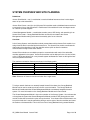
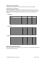
The maximum connection distances are shown in the following table:
Band
Passive Reflector on SM?
Maximum range
2.4 GHz
No
5 miles (8 km)
2.4 GHz
Yes
15 miles (24 km)
5.2 GHz
Not allowed
2 miles (3.6 km)
5.7 GHz
No
2 miles (3.6 km)
5.7 GHz
Yes
10 miles (16 km)
Note: Distances will based on terrain and other line of sight issues.
To bring a network feed out to a remotely located Access Point cluster, the Canopy Backhaul
Module can be used to create a point-to-point link out to the location. The Canopy Backhaul
Module will interface with the Cluster Management Module to seamlessly integrate the entire
system. For more information on the Canopy Backhaul Module see its user manual.
The Cluster Management Module is key to the operation of the Canopy System. At one cluster site
or throughout the system the Cluster Management Module provides a GPS timing pulse to each
module so that their transmission cycles are synchronized. If one Access Point module were to not
be synchronized then it may be transmitting during a receive cycle of the other modules and cause
the receiver to be desensitized. This is also true of the Canopy Backhaul timing master Modules.
AP_CMM2 User Manual Issue 4 Draft
Page 13 of 48
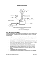
System Wiring Diagram
AP units
GPS sync & Ethernet
cables from each unit*
GPS antenna
GPS antenna
cable
optional
backhaul module
Network Connection
in
Cluster
Management
AP
Installation Kit
Module
300SS
AC or DC
power in
grounding
system
* Cables from only 1 sector are shown in diagram. There are 2 cables,
Ethernet and GPS sync, that would connect each sector unit to the AP
Installation kit.
Figure 4: System Wiring Diagram
SITE SELECTION CRITERIA
There are various issues that need to be taken into consideration when choosing a location for the
network infrastructure. The following is a list of those considerations. There may be others, as
each site is unique.
•
•
•
•
•
•
•
Height is essential when installing Canopy Access Points. The Canopy Access Point
modules must be mounted higher than other objects located immediately around them
such as trees, buildings, and tower legs, but at least 2 feet (0.6 m) below the highest
point on the tower or pole for lightning protection.
There should be no obstructions that will interfere with the unit’s internal antenna. The
area immediately in front of an Access Point module must be clear of all obstructions.
Will the installation area change in the future? Will there be structures high enough to
interfere with the signal? Will trees grow into the line-of-sight path?
When possible, avoid high RF energy sites (i.e. AM/FM stations, high powered
antennas, etc.) Do not place Canopy equipment in the same plane as other RF
equipment.
The means used by the installer to attach the Access Point cluster to the tower,
rooftop, or pole should be rigid and should not move or flex due to wind or other
vibrations.
Tower availability…will a tower have to be erected?
There must be grounding systems available for protection of the Canopy equipment.
AP_CMM2 User Manual Issue 4 Draft
Page 14 of 48
•
Lighting arrestors are required in installation area to transport lightning strikes away
from equipment.
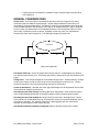
GENERAL CONSIDERATIONS
Fresnel Loss - The Fresnel Zone is a theoretical area around the line of sight of an antenna
transmission that can affect the signal strength. Objects that penetrate the Fresnel Zone can
cause fading of the transmitted signal. This fading is caused by the cancellation of the signal due
to out-of-phase reflections and absorption of the signal. An unobstructed line of sight is important,
but it is not the only determination of an adequate placement. Even though the path has a clear
line of sight, if obstructions (such as terrain, vegetation, metal roofs, cars, etc.) penetrate the
Fresnel zone, there may be signal loss. The following illustrates a Fresnel zone.
Fresnel Zone
D1
D2
Transmitter
Receiver
Figure 5: Fresnel Zone
Free Space Path Loss – As an RF signal travels through space, it is attenuated by the distance
from the initial transmission point. The farther away from the transmission point, the weaker the RF
signal.
Foliage Loss – Tree and plant foliage will cause additional signal loss. Seasonal density, moisture
content of the foliage, and other factors such as wind may change the amount of loss. Caution
should be used when a link may transmit though this type of environment.
Carrier to Interference – describes how much signal advantage must be engineered into the radio
link to tolerate an interfering transmission.
How many Access Point clusters are being planned for deployment? Each cluster will need to
use a Cluster Management Module for seamless operation within the entire Canopy System.
How many Access Point modules are being planned for each site in the deployment? Access
Point modules can be distributed; they do not necessarily have to be mounted immediately next to
each other for operation. For example, if the site is a three-legged tower, two Access Point
modules can be mounted to each of the tower legs.
How will the subscriber modules be deployed relative to planned Access Point clusters?
AP_CMM2 User Manual Issue 4 Draft
Page 15 of 48
CHANNEL PLANS
Whether using 2.4, 5.2, or 5.7 GHz modules, frequencies should never be placed closer
than 20 MHz. 5.2 and 5.7 GHz modules allow the operator to chose frequencies every 5
MHz. 2.4 GHz modules allow the operator to chose frequencies every 2.5 MHz. This is
so that in the event of co-location with other equipment the operator can customize the
channel layout for interoperability.
Backhauls and APs operating in the same frequency band (within the 2.4 GHz band, within the 5.2
GHz band, or within the 5.7 GHz band) need 100 feet (30 m) of physical separation, as their
different transmit and receive frame structures otherwise would cause interference.
2.4 GHz Recommended Frequencies
The following are the 3 non-overlapping channels that are recommended by the Canopy team for
use with an Access Point cluster:
•
•
•
2.415 GHz
2.435 GHz
2.4575 GHz
Note this gives 20 MHz of separation between one pair of channels, and 22.5 MHz of separation
between the other pair. Depending on the RF environment you are operating in, you may want to
put the middle channel at 2.4375 GHz and give additional separation between it and the 2.435 GHz
channel, or move the top channel down to 2.455, or the bottom channel up to 2.4175, as long as
you maintain at least 20 MHz of separation between channels. You can use the Spectrum Analysis
feature in an SM or BHS, or a standalone spectrum analyzer, to help evaluate the RF environment
and guide you in site-specific frequency engineering.
5.2 GHz Recommended Frequencies
The following are the 3 non-overlapping channels that are recommended by the Canopy team for
use with an Access Point cluster:
•
•
•
5.275 GHz
5.300 GHz
5.325 GHz
5.7 GHz Recommended Frequencies
The following are the 6 non-overlapping channels that are recommended for use in an Access
Point cluster when the ISM frequencies are available. Note: only 3 channels are actually needed
for the fully populated cluster. Any of the six channels can also used for backhaul point-to-point
links:
• 5.735 GHz
• 5.755 GHz
• 5.775 GHz
• 5.795 GHz
• 5.815 GHz
• 5.835 GHz
Canopy 5.7 GHz modules can operate up to 5.840 GHz. If your frequency engineering plan allows,
consider using the additional 5 MHz of separation between your AP frequencies and your backhaul
frequencies.
AP_CMM2 User Manual Issue 4 Draft
Page 16 of 48
Single Access Point Module
A single Access Point module can use any of the frequency channels that are available.
Single Access Point Cluster
Use the following table as a recommendation to assign frequency channels and sector IDs (see
section on Configuration interface screen for information on sector IDs). Each frequency is reused
on the sector that is at a 180-degree offset. Symbol refers to the layout in the diagram below
(Figure 6).
2.4 GHz Plan
Direction of Access Point
sector
North – (0°)
Northeast – (60°)
Southeast – (120°)
South – (180°)
Southwest – (240°)
Northwest – (300°)
Frequency
2.415 GHz
2.435 GHz
2.4575 GHz
2.415 GHz
2.435 GHz
2.4575 GHz
Sector ID
Symbol
0
1
2
3
4
5
A
B
C
A
B
C
Frequency
5.275 GHz
5.300 GHz
5.325 GHz
5.275 GHz
5.300 GHz
5.325 GHz
Sector ID
0
1
2
3
4
5
Symbol
A
B
C
A
B
C
Frequency
5.735 GHz
5.755 GHz
5.775 GHz
5.735 GHz
5.755 GHz
5.775 GHz
Sector ID
0
1
2
3
4
5
Symbol
A
B
C
A
B
C
5.2 GHz Plan
Direction of Access Point sector
North – (0°)
Northeast – (60°)
Southeast – (120°)
South – (180°)
Southwest – (240°)
Northwest – (300°)
5.7 GHz Plan
Direction of Access Point sector
North – (0°)
Northeast – (60°)
Southeast – (120°)
South – (180°)
Southwest – (240°)
Northwest – (300°)
Multiple Access Points Clusters
When deploying multiple Access Point cluster in a given area it is recommended that the clusters
be aligned in the following manner.
AP_CMM2 User Manual Issue 4 Draft
Page 17 of 48
A
A
C
B
B
C
C
B
B
C
A
C
A
A
B
B
C
A
C
B
A
A
B
C
A
C
B
A
C
B
C
A
B
A
C
B
B
B
C
A
C
A
Figure 6: Laying out multiple Access Point clusters
AP_CMM2 User Manual Issue 4 Draft
Page 18 of 48
NETWORKING INFORMATION
The Canopy Access Point module will each use an IP address on the operator’s network. It is
recommended that the Access Point modules never be placed directly onto the Internet. IP
addresses may be assigned sequentially clockwise around an Access Point cluster for easier
manageability. The operator will also need to identify the appropriate subnet mask and network
gateway each of the modules.
From the factory, each Access Point module is assigned a unique MAC address and the following
default networking information:
•
•
•
IP address of 169.254.1.1
Subnet mask of 255.255.0.0
Network gateway of 169.254.0.0
LIGHTNING PROTECTION
•
The Canopy Access Point module, Cluster Management Module, and GPS antenna must
be mounted at least 2 feet below the highest point at the site for lightning strike mitigation.
It is highly recommended that the site have a lightning protection system installed.
•
Ensure the location is properly grounded for lightning protection according to all applicable
national and local codes.
•
To protect operator equipment from surges on the Ethernet cable that is connected to the
Canopy System, the Canopy surge suppressor must be used.
ELECTRICAL REQUIREMENTS
•
Specifications for the voltages and distance can be found in the Specification section of
this manual.
•
There is a fuse in the CMM for short-circuit protection. In addition, good electrical practice
requires a circuit breaker in the electrical circuit supplying the CMM, or other means to
provide a disconnect device and back-up short-circuit protection.
•
Make certain the installation conforms to applicable country and local codes, such as the .
National Electrical Code (NEC) in the US. If uncertain of code requirements, obtain the
services of a licensed electrician.
AP_CMM2 User Manual Issue 4 Draft
Page 19 of 48
ADVANCED FEATURES
These features may be used in the Canopy System but are not required for basic operation.
SECURITY - DES ENCRYPTION
Standard Canopy modules provide Data Encryption Standard (DES) encryption. DES is a secret
key encryption scheme using a 56 bit key. The basics of DES are that it performs a series of bit
permutations, substitutions, and recombination operations on blocks of data using a secret key.
On the Canopy system, encryption of the over the air link is enabled or disabled per Access Point
module or per Backhaul timing master module. The Canopy modules contain unique factory
programmed secret keys to establish the encrypted link. If an authentication key (must be the same
key on each end of the backhaul link) has been entered using the Backhaul Configuration page,
then that key is also used to establish the DES encryption key. Encryption does not affect the
performance or throughput of the system.
SECURITY - AES ENCRYPTION
Motorola also offers Canopy products that provide Advanced Encryption Standard (AES)
encryption. Like DES, AES is a secret key encryption scheme, but AES uses the Rijndael algorithm
and 128 bit keys to establish a higher level of security than DES.
Due to the level of security provided by AES, the US government has established export controls
on communications products that use AES. These export controls may mean that outside of the US
AES products
Canopy
AES products
are only run
available
the same
in certain
software
regions
as DES
– check
products,
with your
so the
Canopy
features
distributor
availableorare
reseller
for availability
exactly
the same
in your
and area.
work the same with the only exception being that the AES products provide
AES instead of DES encryption when enabled for encryption on the Configuration screen. All the
interface screens, Status pages, Configuration pages, etc. are identical. As new software features
become available on DES products, the same software and the same features will be available for
AES products.
DES backhauls are available in both 10 Mbps and 20 Mbps signaling rates. AES backhauls are
only available with a 10 Mbps signaling rate.
Canopy DES products are not upgradeable to AES. To have the option of AES encryption, you
must purchase AES products.
Canopy AES products use a different FPGA load than DES products. However, the FPGA will be
upgraded as needed to provide new features or services similar to the DES products.
The same as with DES, encryption of the over the air link is enabled or disabled per Access Point
module or per Backhaul timing master module. The Canopy modules contain unique factory
programmed secret keys to establish the encrypted link. If an authentication key (must be the same
key on each end of the backhaul link) has been entered using the Backhaul Configuration page,
then that key is also used to establish the AES encryption key.
Canopy AES products and DES products do not interoperate when enabled for encryption, as DES
and AES are different encryption schemes. An AES AP with encryption enabled can only
communicate with AES SMs, and similarly an AES Backhaul timing master module with encryption
enabled can only communicate with an AES Backhaul timing slave module. However, if encryption
is disabled, AES modules can communicate with DES modules.
AP_CMM2 User Manual Issue 4 Draft
Page 20 of 48
BANDWIDTH MANAGEMENT
Subscriber Module bandwidth management is set per Access Point. All Subscriber Modules which
register to an Access Point module will receive and use the same bandwidth management
information.
The software uses “token buckets” to manage each subscriber’s bandwidth. Each subscriber’s
bucket (actually two buckets, one for uplink and one for downlink) is constantly being filled with
tokens at the Sustained rate, up to the Burst size (the size of their bucket). When they use the
internet, they have full bandwidth until they “drain” their bucket, then they only have the Sustained
rate, until they quit draining their bucket, and let it refill a bit.
After a burst is fully or partially used, it then “recharges” at the Sustained rate. Short bursts
recharge quickly, often before the next burst. Large bursts take longer to recharge.
The way bandwidth management appears to the subscriber is that as long as they are doing
normal web browsing and e-mail handling, small file transfers, and short streaming video, they will
rarely be speed limited, depending on what the bandwidth management is set to. If they do large
downloads (software upgrades, streaming video, and so on), or a series of medium-size
downloads, they will have high bandwidth until they hit the burst limit, then drop down in speed to
the sustained setting. When they are idle, the burst limit will then “recharge” at the sustained rate.
To manage bandwidth separately for each SM, Canopy offers the Bandwidth and Authentication
Manager (BAM). The BAM supports per-SM setting of Sustained Uplink, Sustained Downlink,
Uplink Burst, and Downlink Burst, as well as SM authentication and user-specification of DES keys.
The BAM is a Canopy software product running on a networked Linux PC.
HIGH PRIORITY BANDWITH
To support traffic with a low latency requirement such as VoIP (voice over IP), the Canopy System
implements a high priority data pipe. This implementation does not affect the inherent latencies in
the Canopy System but allows high priority traffic to be serviced immediately. The high priority pipe
separates low latency trafiic from traffic that is latency tolerant such as standard web surfing and
file downloads. This traffics is separated by the Canopy System via the IPv4 TOS (type of service)
Low Latency bit. If this bit is set, the packet will be sent on the high priority pipe. This pipe is
serviced before any normal priority traffic.
The high priority system is enabled via four fields found in the Configuration web page. The fields
are:
• High Priority Uplink Percentage
• Uacks Reserved High
• Dacks Reserved High
• NumCtrlSlots Reserved High
The High Priority Uplink Percentage parameter describes the percentage of the uplink bandwidth
that will be dedicated to low latency traffic. When set, this percentage of RF link bandwidth will be
permanently allocated to low latency traffic regardless of the amount of this kind of traffic present.
There is no corresponding downlink parameter as this bandwidth is allocated on as-needed basis
by the scheduling algorithms.
The UAcks (Uplink ACK) Reserved High parameter describes the number of slots used to
acknowledge high priority data that is received by a subscriber module. The Canopy team
recommends that this parameter be set to 3 and then the TotalNumUAcksSlots parameter should
be set to 6.
AP_CMM2 User Manual Issue 4 Draft
Page 21 of 48
The DAcks (Downlink ACK) Reserved High parameter describes the number of slots used to
acknowledge high priority data that is received by an Access Point module. The Canopy team
recommends that this parameter be set to 3 and NumDAckSlots parameter should be set to 6.
The NumCtrlSlots Reserved High parameter describes the number of slots used to send control
messages to an Access Point module. The Canopy team recommends that this parameter be set
to 3 and the NumCtlSlots parameter should be set to 6.
When all these parameters are configured, all high priority traffic in the uplink direction will be
serviced via this pipe at the percentage configured. This is true even if the high priority traffic
volume exceeds the configured capacity and there is no non-high priority traffic.
BRANDING
On each Canopy module, the web-based interface screens have a Canopy logo that can be
replaced with an operator’s company logo. The Canopy logo file is called canopy.jpg and the
replacement file must also be called canopy.jpg. The new file is transferred via FTP to the module
and then added to a special filesystem through a telnet session. The following command can be
used during a telnet session:
•
•
•
addwebfile – add a custom logo file to the filesystem
clearwebfile – clear the customer logo file from the filesystem
lsweb – list the custom logo file and display the storage space available on the filesystem
The following is a sample FTP session:
> ftp 169.254.1.1
Connected to 169.254.1.1
220 FTP server ready
Name (169.254.1.1:none): root
331 Guest login ok
Password: <password-if-configured>
230 Guest login ok, access restrictions apply.
ftp> binary
200 Type set to I
ftp> put canopy.jpg
ftp> quit
221 Goodbye
The following is a sample telnet session:
/---------\
C A N O P Y
Motorola Broadband Wireless Technology Center
(Copyright 2001, 2002 Motorola Inc.)
Login: root
Password: <password-if-configured>
Telnet+> lsweb
Flash Web files
free directory entries: 32
free file space
64336 bytes
Telnet+> addwebfile canopy.jpg
Telnet +> lsweb
Flash Web files
/canopy.jpg
7867
free directory entries: 31
free file space: 56468
AP_CMM2 User Manual Issue 4 Draft
Page 22 of 48
Telnet +> clearwebfile
Telnet+> lsweb
Flash Web files
free directory entries: 32
free file space
64336 bytes
SNMP
Simple Network Management Protocol (SNMP) can be used to monitor the Canopy modules. The
standard MIB-II (systems and interfaces) objects are programmed into the modules. For specific
information on this MIB see RFC 1213 for details.
With Canopy Release 3.2, the Canopy Enterprise MIB is available for additional information
reporting and control. Consult the Release 3.2 Software Release Notes for additional information.
AP_CMM2 User Manual Issue 4 Draft
Page 23 of 48
INSTALLATION
The following steps are required to install the Canopy Access Point module(s), the Cluster
Management Module, and the GPS antenna:
• Unpack the Canopy products
• Configuration of the Access Point modules
• Configuration of the Cluster Management Module
• Installation of the Access Point modules, Cluster Management Module, and GPS antenna
• Verification
UNPACK THE CANOPY PRODUCTS
Upon receipt, carefully inspect all shipping boxes for signs of damage. If there is damage,
immediately notify the transporatation company.
Unpack equipment, making sure that all ordered components have arrived. It is recommended that
you save all the packing materials. They can be used for transportation of the equipment to and
from installation sites.
CONFIGURATION OF THE ACCESS POINT MODULES
In all cases, for configuration changes to take effect, the operator must
1. Make the configuration change or changes on a module’s web page.
2. Save the configuration change or changes, using the Save button.
a. Make and Save additional configuration changes if desired.
3. Reboot the module, using the Reboot button.
The configuration changes don’t take effect until the module is rebooted.
The are two methods that can be used to configure each of the Access Point modules. The first
method is to use the Quick Start feature of the product. For more information on Quick Start see
The Interface Screens. The second is to manually set each of the parameters.
The Access Point module, from the factory, is configured to not transmit on any frequency. This is
done so that an operator does not accidentally turn on an unsynchronized Access Point module.
An operator will need to verify the following information:
• Will the Access Point module need to generate its own sync pulse or will it receive it
from the Cluster Management Module?
• The operator will assign a RF frequency for the module to transmit.
• The operator may assign value for uplink and downlink bandwidth capping. If the
Access Point module is in a cluster with other modules then this parameters on all
units must be set exactly the same.
• The operator will assign an IP address to the module for the network it will be installed
on and assign an appropriate subnet mask and network gateway.
• The operator must configure the appropriate color code on the Access Point module so
that subscriber modules can register with it. The color codes must match for
registration.
• The operator must configure the maximum range that the Access Point module will
register a subscriber module. If the Access Point module is in a cluster with other
modules then this parameter on all units must be set exactly the same.
• The operator can prevent unauthorized users from connectig to the Access Point
module’s web based interface by assigning a password. There is no default password
and password protection is turn off is turn off from the factory.
AP_CMM2 User Manual Issue 4 Draft
Page 24 of 48
Passwords can be from 1 to 16 characters. Any combination of characters
is allowed, except for these special characters: “ , . ‘ { } / \ ; : [ ] ( ) ` ~
- NOTE: If the operator forgets either the password or the IP address for
the module, a Canopy default plug can be used to regain access. For
details, see the section on the default plug under Interface Screens.
- There are two types of passwords that can be configured: display-only or
full-access. The display-only password allows the operator to view the
module’s current status. The full-access password allows the operator to
view the module’s current status and change its configuration. By viewing
the red lettering to the right of the entry fields, the operator can tell that a
password is set, but can’t see the password.
The operator can enter information about the Site Name, Location, and Contact. This
is optional.
-
•
CONFIGURATION OF THE CLUSTER MANAGEMENT MODULE
The operator will need to verify the following when configuring a Cluster Management Module:
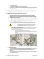
• What type of power will the module use, AC or DC?
• If using AC power, there is a switch to choose 115V or 230V on the
power transformer. This switch must be set correctly before power is
applied, or the unit may be damaged. See the schematic inside the
Cluster Management Module for further information.
Fuse receptacle
AC power
connectors
115/230 V switch
Figure 7: Location of 115/230 V Switch
•
•
The AC power connectors are labeled
- N for Neutral
- L for Line
- PE for Protective Earth (PE)
(ground)
The maximum thickness wire to be used is 12 AWG (4 mm2).
INSTALLATION OF THE EQUIPMENT
The following tools may be needed during installation:
• 3/8” nut driver
AP_CMM2 User Manual Issue 4 Draft
Page 25 of 48
•
•
•
•
12” adjustable wrench
7/16” wrench for installation of GPS mounting bracket
14mm wrench for installation of Cluster Management Module pole-mounting brackets
Needle-nose pliers
When power is applied to a Canopy module or the unit reset via the web-based interface, the
module will take approximately 25 seconds to boot up. During this boot up time, power on selftests and other diagnostics are being performed.
The following steps are needed to install the Canopy equipment:
•
•
•
•
Remove the base cover from all Canopy Access Point modules to be installed.
Remove the GPS sync cable knockout from the base cover with needle-nose pliers.
Mount the Access Point modules:
- The modules can be mounted in a variety of locations, choose the best location
for your particular application. Modules do not have to mounted directly next to
each other, they can be distributed throughout a given site. Mounting can be done
by using stainless steel hose clamps or another equivalent fastener.
Mount the Cluster Management Module
- Mount the module in a location that will allow access for service if necessary.
-
-
The farthest that the Access Point modules can be from the
Cluster Management Module is 328 feet (100 meters).
The module should not be mounted closer than 10 feet (3 meters) to the Access
Point modules or Backhaul Modules
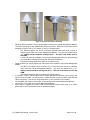
The module box has flanges for ease of installation. Hardware is included to
support different mounting options:
- Directly to a wall (screws or bolts not included)
- Around irregular shaped objects (via adjustable stainless steel bands,
included)
- To a pole with an outside diameter of 1.25 to 3.00 inches
(approximately 3 to 8 cm). (toothed V brackets, included).
Figure 8: Detail of pole mounting
•
Mount the GPS antenna
- The GPS antenna must be located so that it has an unobstructed view of the sky (20degrees off the horizon) and is not the highest item at the installation site (for
lightning).
- The GPS antenna mount is provided with U-bolts for pole sizes of 1.25 to 1.50 inches
(approximately 3 to 4 cm).
AP_CMM2 User Manual Issue 4 Draft
Page 26 of 48
Figure 9: Detail of GPS antenna mounting
•
•
•
•
•
•
Route the Ethernet cables from the Access Point modules to the Cluster Management Module.
The strain relief plugs on the CMM already have precut holes. Each hole of the strain relief is
designed to hold two CAT 5 UTP cables, or one if it is shielded cable.
- The Ethernet cables use RJ-45 connectors (standard Ethernet) that connect to
matching ports within the Cluster Management Module. The ports are labeled with a
“J3”. Always connect modules starting at port 1. This port is the master port for
the CMM.
- A total of 8 ports are available on the Cluster Management Module to accommodate
any combination of Access Point modules and Backhaul Modules.
- Connect the remaining Ethernet cables in the same manner.
Route the GPS sync (serial) cables from the Access Point modules to the Cluster Management
Module.
- The GPS sync cables use 6 conductor RJ-11 connectors that connect to matching
ports within the Cluster Management Module. The ports are labeled with a “J1 ”.
Always connect modules starting with port 1. This port is the master port for the
CMM.
- Connect the remaining GPS sync cables in the same manner.
If necessary, route a network cable into the Cluster Management Module and connect to the
uplink port on the switch. As with any such installed devices, proper grounding of the Ethernet
cable is necessary. The Canopy Surge Suppressor is such a device for this situation.
Connect GPS coax cable to N-connector on the outside of the Cluster Management Module.
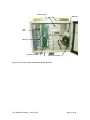
Connect AC or DC power to the Cluster Management Module.
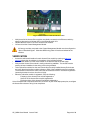
When power is applied the “power ” LED on the Ethernet switch should come on as well a
green LED on the circuit board as show in the following figure.
AP_CMM2 User Manual Issue 4 Draft
Page 27 of 48
Figure 10: Port indicator LED on Ethernet switch
•
•
•
Verify that all of the Access Point modules are reliably connected to the Ethernet switch by
observing that each port indicator LED on the Ethernet switch is lit.
Replace the base cover on all of the Access Point modules.
Close and lock the Cluster Management Module.
All Canopy modules connected to the Cluster Management Module must be configured to
“Sync to Received Signal”. Otherwise GPS timing pulse will not be transmitted to the
modules.
VERIFICATION
•
Access the web based interface for each Access Point module by opening up http://<ipaddress> where the <ip-address> is the address of the individual module.
• Click on “GPS Status” from the menu located on the left hand side of the web page.
• Verify that the Access Point module is seeing and tracking satellites. The module must be
tracking at least 4 satellites for the timing pulse to be generated.
• Take a subscriber module into the area surrounding the newly installed Access Point cluster
and verify that the subscriber module registers to each of the installed Access Point modules.
The subscriber must have the same color code as the Access Point for successful registration
(assuming that there is also a clear line-of-sight).
• When the subscriber module is registered, verify the following:
- Frequency of the Access Point module registered to
- Sector ID of the Access Point module registered to
- Physical position of the Access Point Module registered to
If the information that is reported back does not conform to your initial deployment plan, reconfigure
the Access Point cluster to bring it into compliance.
AP_CMM2 User Manual Issue 4 Draft
Page 28 of 48
CABLING
It is strongly recommended to use shielded cable for all Canopy infrastructure cabling associated
with Backhauls, Access Points, and Cluster Management Modules. The environment these
modules operate in often has significant or unknown or varying RF energy, and experience has
been that the additional cost of shielded cabling is more than compensated by predictable
operation and reduced debugging and support costs.
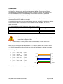
The following information describes the wiring standards for installing a Canopy system. All
diagrams use the EIA/TIA 568B color standard.
Currently shipping modules auto-sense the Ethernet cable type – either RJ-45 straight-thru cable or
RJ-45 crossover cable can be used to connect a network interface card (NIC), hub, router, or
switch to a module.
The following table shows MAC Addresses of Auto-sensing modules:
MAC Address (ESN)
Non-auto-sensing
Auto-sensing
2.4 Modules
All
5.2 Modules
≤ 0a003e0021c8
≥ 0a003e0021c9
5.7 Modules
≤ 0a003ef00f79
≥ 0a003ef00f7a
Very early modules did not auto-sense. In cases where older modules are used:
•
•
When connecting a Canopy device directly to a network interface card (NIC)
use a RJ-45 straight-thru cable.
When connecting a Canopy device directly to a hub, switch, or router use a RJ-45
crossover cable.
When using the Canopy AC wall adapter the +V is +11.5VDC to +30VDC with a nominal value of
+24 VDC, and the maximum Ethernet cable run with the AC wall adapter is 328 feet (100 meters).
RJ-45 Straight-Thru:
pin 1 →
pin 2 →
pin 3 →
pin 4 →
pin 5 →
pin 6 →
pin 7 →
pin 8 →
white / orange
orange
white / green
blue
white / blue
green
white / brown
brown
← pin 1
← pin 2
← pin 3
← pin 4
← pin 5
← pin 6
← pin 7
← pin 8
Pin
RJ-45 Straight-Thru
Pin
TX+ 1
1 RX+
TX- 2
2 RX-
RX+ 3
3 TX+
4
4
5
5
+V
+V
RX- 6
+V
return
6 TX-
7
7
8
8
+V
return
Pins 4, 5, 7, and 8 are used to carry power to the Canopy modules.
AP_CMM2 User Manual Issue 4 Draft
Page 29 of 48
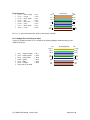
RJ-45 Crossover:
pin 1 →
pin 2 →
pin 3 →
pin 4 →
pin 5 →
pin 6 →
pin 7 →
pin 8 →
white / orange
orange
white / green
blue
white / blue
green
white / brown
brown
Pin
← pin 3
← pin 6
← pin 1
← pin 4
← pin 5
← pin 2
← pin 7
← pin 8
RJ-45 Crossover
Pin
TX+ 1
3 RX+
TX- 2
6 RX-
RX+ 3
1 TX+
4
4
5
5
+V
+V
RX- 6
+V
return
2 TX-
7
7
8
8
+V
return
Pins 4, 5, 7, and 8 are used to carry power to the Canopy modules.
RJ-11 Straight-Thru (for GPS sync cable)
Using CAT 5 cable and 6-pin RJ-11 connectors, the following diagram shows the wiring of the
cable for GPS sync.
Pin
1-pps 1
pin 1 → white / orange
pin 2 → white / green
pin 3 → white / blue
pin 4 → green
pin 5 → blue
pin 6 → orange
the 4th pair is not used
← pin 1
← pin 2
← pin 3
← pin 4
← pin 5
← pin 6
AP_CMM2 User Manual Issue 4 Draft
RJ-11 Straight-Thru
Pin
1 1-pps
TX+ 2
2 RX+
RX+ 3
3 TX+
not
used
4
4
5
5
not
used
gnd 6
6 gnd
not
used
not
used
Page 30 of 48
THE INTERFACE SCREENS
The Canopy Access Point module contains a series of web pages that are used to interface to the
unit. The following is a quick reference to interface screens. Note: These screens are subject to
change by subsequent software versions. To access the web based interface you first must be on
a computer that is in some way connected to the Access Point module. This can be done either
directly or through a network. Enter the IP address of the Access Point module (default is
169.254.1.1) into the address bar of your browser and hit enter on your keyboard. The following
web based interface pages are accessible:
•
•
•
•
•
•
•
•
•
•
•
Quick Start
Status
Configuration
Event Log
LUID Select
Link Test
Time & Date
Sessions
GPS Status
Ethernet Stats
ExtendedStats
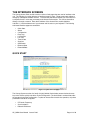
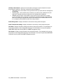
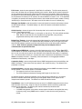
QUICK START
Figure 11: Quick Start web page
The Canopy System consists of a family of highly flexible, fixed wireless access devices that can
be put into service quickly and with a minimal configuration. The Quick Start is a wizard that walks
the operator through that configuration. To place an Access Point module into operation, only three
parameters need to be configured:
•
•
•
RF Carrier Frequency
Synchronization
Network IP Address
AP_CMM2 User Manual Issue 4 Draft
Page 31 of 48
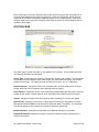
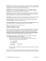
Each of the pages in the Quick Start will explain a little about Canopy and ask the operator for a
choice that best addresses the network requirements. At the end, the operator will be given the
opportunity to review the configuration selected and save it to non-volatile memory. None of the
changes made prior to saving the configuration will affect the system so experimentation with the
interface is encouraged.
STATUS PAGE
Figure 12: Status web page
The Status page contains information on the operation of the product. It is the default web page.
The following parameters are displayed:
Device Type: displays the type of Canopy module that is currently being viewed. This field will let
the operator know the frequency band of the module, the protocol that it is utilizing, and the MAC
address of the module. The frequency band can either be in the 2.4, 5.2, or 5.7 GHz band.
Software Version: displays the version of the software that is currently loaded into the module.
Please make note of this information when obtaining technical support.
FPGA Version: displays the version of the FPGA (field programmable gate array) that is currently
loaded into the module. Please make not of this information when obtaining technical support.
Uptime: displays the length of time the module has been operating since power was applied.
System Time: displays the current time. If the Access Point module is connected to a Cluster
Management Module (CMM) then the time will be Greenwich Mean Time (GMT). Any subscriber
module that registers to the Access Point module will inherit the system time.
Ethernet Interface: displays the configuration of the Ethernet interface on the module.
Registered SM Count: displays the number of subscriber modules currently registered to the
Access Point module.
AP_CMM2 User Manual Issue 4 Draft
Page 32 of 48
GPS Sync Pulse Status: displays the current status of the type of synchronization the Access
Point module is receiving. There are 3 values that could be displayed:
• Generating sync: If the module is set to generate its own sync pulse then this message will
be displayed.
• Receiving Sync: If the module is set to receive a sync pulse from an outside source (not
itself) and is actually receiving the pulse then this message will be displayed.
• ERROR: No Sync Pulse: If the module is set to receive a sync pulse from an outside
source (not itself) and it is currently not receiving the pulse this message will be displayed.
When this message is displayed the Access Point module will turn its transmitter off so as
to not create any self-interference within the Canopy System.
Radio Slicing Value: displays information to be used be Canopy technical support.
Radio Transmit Gain Setting: displays information to be used by Canopy technical support.
Site Name: displays information relating to the name of the physical module. This parameter can
be set by the operator on the Configuration web page. This information is set into the sysName
SNMP MIB-II object and can be polled via a SNMP management server.
Site Contact: displays contact information for the physical module. This parameter can be set by
the operator on the Configuration web page. This information is set into the sysContact SNMP MIBII object and can be polled via a SNMP management server.
AP_CMM2 User Manual Issue 4 Draft
Page 33 of 48
CONFIGURATION
Figure 13: Configuration web page
The Configuration web page contains information and configurable parameters pertaining to the
operation of the product. The first line of information on the Configuration screen is a repeat of the
Device Type from the Status web page. The following are the parameters and their descriptions.
Sync Input: choose the type of synchronization that this Access Point module will use.
If “Sync to Received Signal” is chosen, then it is assumed that:
•
•
this Access Point module it connected to a Cluster Management Module and will be
receiving a sync pulse via GPS
this Access Point module is connected to another Access Point module that is generating
its own sync pulse.
If “Generate Sync Signal” is chosen then it is assumed that:
•
•
this Access Point module is a stand-alone module with no other Access Point modules
within a 5 mile radius.
this Access Point module is generating the sync pulse for a cluster of Access Point
modules and there are no other Access Point modules within a 5-mile radius.
Link Negotiation Speeds: choose the type of link speed desired for the Ethernet connection. The
default for this parameter is for all the choices to be checked.
RF Frequency Carrier: choose the frequency that the module will transmit on. The default from
the factory is to have this parameter set to none.
Downlink Data: choose the percentage of the aggregate throughput that is needed for the
downlink (i.e going from the Access Point module to the subscriber). For example, if the aggregate
throughput on the Access Point module is 6 Mbits, then configuring this parameter for 75% will
allocate 4.5 Mbits for the downlink and 1.5 Mbits for the uplink. If the Access Point module is in a
AP_CMM2 User Manual Issue 4 Draft
Page 34 of 48
cluster with other modules then this parameter on all units must be set exactly the same. The
default for this parameter is 75%.
High Priority Uplink Percentage: describes the percentage of the uplink bandwidth that will be
dedicated to low latency traffic. When set, this percentage of RF link bandwidth will be
permanently allocated to low latency traffic regardless of the amount of this kind of traffic present.
There is no corresponding downlink parameter as this bandwidth is allocated on as-needed basis
by the scheduling algorithms.
Total NumUAckSlots: describes the total number of slots used to acknowledge data that is
received by a subscriber module. If the Access Point module is in a cluster with other modules
then this parameter on all units must be set exactly the same. The default should be set to 3.
Uacks Reserved High: describes the number of slots used to acknowledge high priority data that
is received by a subscriber module. The Canopy team recommends that this parameter be set to 3
and then the Total NumUAcksSlots parameter should be set to 6.
NumDAckSlots: describes the total number of slots used to acknowledge data that is received by
an Access Point module. If the Access Point module is in a cluster with other modules then this
parameter on all units must be set exactly the same. The default should be set to 3.
Dacks Reserved High: describes the number of slots used to acknowledge high priority data that
is received by an Access Point module. The Canopy team recommends that this parameter be set
to 3 and NumDAckSlots parameter should be set to 6.
NumCtlSlots: describes the total number of slots used to send control messages to an Access
Point module. If the Access Point module is in a cluster with other modules then this parameter on
all units must be set exactly the same. The default should be set to 3.
NumCtlSlots Reserved High: describes the number of slots used to send control messages to an
Access Point module. The Canopy team recommends that this parameter be set to 3 and the
NumCtlSlots parameter should be set to 6.
Sustained Uplink Data Rate: choose the rate at which each Subscriber Module registered to this
AP will be capped in the uplink direction. The default is 10,000 kbps, which means that there is no
restriction on the uplink.
Uplink Burst Allocation: choose the maximum value that each individual subscriber module will
have for burst traffic in the uplink direction. The default is 10,000 kb.
Sustained Downlink Data Rates: choose the rate at which each Subscriber Module registered to
this AP will be capped in the downlink direction. The default is 10,000 kbps, which means that
there is no restriction on the downlink.
Downlink Burst Allocation: choose the maximum value that each individual subscriber module
will have for burst traffic in the downlink direction. The default is 10,000 kb.
LAN IP: enter in the IP address that will be associated with the Ethernet connection on this
module. The default address is 169.254.1.1. If the IP address is forgotten, the operator will need
physical access to the module and will need to create a Canopy “default plug”. See steps at the
end of this section for use of a default plug.
AP_CMM2 User Manual Issue 4 Draft
Page 35 of 48
LAN Subnet Mask: enter in an appropriate subnet mask for the module to “talk” on the network.
The default value for this parameter is 255.255.255.0.
Default Gateway: enter in the appropriate gateway for the module to “talk” on the network. The
default for this parameter is 169.254.0.0.
Private IP: the default for this parameter is 192.168.101.1. It is recommended that the operator
not change this parameter. A flat, class C subnet is used to communicate with each of the
subscriber modules that have registered. The Access Point uses a combination of the private IP
and the logical unit ID (LUID) of the subscriber module.
For example, if there are two subscriber modules (LUID 2 and LUID 3) registered to an Access
Point module, then the Access Point uses the following to communicate to each:
Unit
Access Point module
subscriber module 1
subscriber module 2
LUID
Private IP
1
2
3
192.168.101.1
192.168.101.2
192.168.101.3
If the private IP address is changed then it must designate a Class C subnet that is not used for
anything else and the address must be in the form of xxx.xxx.xxx.1, where 1 is the last octet of the
address.
Color Code: enter in a value (0-254). The color code on the subscriber module and the Access
Point module must match in order for registration to occur. Color code is not a security feature. It
is a means for the Canopy System operator to segregate an individual network or neighbor Canopy
networks. Also, color code can be used to force a subscriber module to only register to a specific
Access Point module even though the subscriber module may be able to see multiple Access Point
modules. The default value for this parameter is 0 on all Canopy modules.
Sector ID: choose an ID number to give to this Access Point module. This parameter does not
affect the operation of the module in any way. Its purpose is just another means to identify the
Access Point module. When observing a subscriber module’s AP Eval Data web page, the sector
ID is one of the distinguishing fields present to help the operator understand what Access Point
module is seen. It is recommended that when constructing an Access Point cluster (2-6 modules)
that each sector be given a different ID and that the pattern be repeated throughout the entire
Canopy System for manageability.
Max Range: enter in a distance (in miles). This parameter controls the maximum distance that a
subscriber module will be allowed to register. The subscriber module must still meet minimum
requirements for an acceptable link in order to register. If the Access Point module is in a cluster
with other modules then this parameter on all units must be set exactly the same. The default for
this parameter is 2 miles.
Display-Only Access: enter the same password in both fields for verification. The display-only
password, when used, will allow only view activities to the module. When the display-only
password is set and not the full-access password, the display-only password will be tied to telnet
and FTP sessions to the module. If the full-access password is also set then it has precedence on
the telnet and FTP sessions. If the password is forgotten, the operator will need physical access to
the module and will need to create a Canopy “default plug” to override the unit. See steps at end of
section for use and creation of a default plug.
AP_CMM2 User Manual Issue 4 Draft
Page 36 of 48
Full Access: enter the same password in both fields for verification. The full-access password,
when used, will allow view and change activities to the module. When the full-access password is
set, the password will also be tied to telnet and FTP sessions to the module. When prompted for
the password via the web-based interface, there is no username required; however when prompted
for the password via a telnet or FTP session, the user that MUST be used is “root”. If the password
is forgotten, the operator will need physical access to the module and will need to create a Canopy
“default plug” to override the unit. See steps at end of this section for use of a default plug.
Webpage Auto Update: enter time period (in seconds) desired to have the web browser refresh
the web-based interface. The default setting is 0, which will cause the web-based interface to
never refresh.
Airlink Security: choose the type of air link security that is to be used on this Access Point
module. There are two choices:
• Normal: With this mode there is no encryption on the air link. This is the default operation.
• DES: With this mode the air link is encrypted using single DES, using a factory
programmed secret key that is unique for each module.
Bridge Entry Timeout: choose the appropriate bridge timeout for correct network operation with
existing network infrastructure. It is important that this parameter be set for a longer time period
than the ARP (address resolution protocol) cache timeout of the router being used to feed the
network. Note: Failure to properly configure this may lead to temporary loss of
communication to specific end users.
AP Background BER Mode: choose to have this feature turned on or off. Bit Error Rate (BER)
mode will allow an operator another means to verify the functionality of a link. When BER mode is
turn on a bit error rate can be read on the subscriber side to determine the quality of a registered
link. If the Access Point module is in a cluster with other modules then this parameter on all units
must be set exactly the same. Continually, when this feature is on the aggregate available
bandwidth will decrease by ~200 Kbps.
Community String: enter a string that will allow a SNMP management server accessibility to the
SNMP information. There must not be any spaces in the community string. The default for this
parameter is “Canopy”.
Accessing Subnet: enter the network that will be allowed to access SNMP information from the
canopy module. There are two pieces of information needed:
• The network in the form of xxx.xxx.xxx.xxx
• The CIDR (Classless Interdomain Routing) prefix length in the form of /xx
An example would be 198.32.0.0/16 where /16 is a subnet mask of 255.255.0.0. An Internet
search on Classless Interdomain Routing will provide greater detail on this subject for the
inexperienced network operator. The default is to allow all networks access.
Trap Address: enter in an IP address (xxx.xxx.xxx.xxx) of an SNMP management server where
trap information can be sent. A trap is a way for the module to tell the monitoring system that
something has happened. The following are scenarios where traps would be sent:
• after a reboot of the module
• if a SNMP management server tried to access agent information and supplied the wrong
community string, wrong SNMP version number, or came from the wrong accessing
subnet.
AP_CMM2 User Manual Issue 4 Draft
Page 37 of 48
Site Name: enter information relating to a name given to the physical module. This parameter will
set the supplied information into the sysName SNMP MIB-II object and can be polled by a SNMP
management server. The buffer size for this field is 128 characters.
Site Contact: enter contact information relating to the module. This parameter will set the
supplied information into the sysContact SNMP MIB-II object and can be polled by a SNMP
management server. The buffer size for this field is 128 characters.
Site Location: enter information relating to the physical location of the module. This parameter
will set the supplied information into the sysLocation SNMP MIB-II object and can be polled by a
SNMP management server. The buffer size for this field is 128 characters.
Save Changes: by clicking on this button, any changes that have been made on the Configuration
page will be committed to flash memory and will take effect after the next module reboot.
Undo Save Changes: by clicking on this button, any changes that have been made and not
committed through a reboot of the module will be undone.
Set to Factory Defaults: depressing this button will change all of the configurable parameters (all
of which are contained on the Configuration page) back to their factory settings.
Reboot: depressing this button will reboot the module.
CANOPY DEFAULT PLUG
When inserted, the default plug brings the module up with a default configuration. This allows the
operator to regain control of a module, which may be using an IP address and/or password that
has been forgotten. The default plug will also override the passwords for access and change
control and set the LAN1 IP address back to 169.254.1.1. This does not, by itself, change any
configuration, rather, it allows the operator to attach to the module using the default configuration
so that they can read the actual non-default values and set them accordingly.
The following steps outline the creation of a default plug (this plug can also be purchase for a
nominal fee at http://www.best-tronics.com/motorola):
• Obtain a RJ-11, 6-pin connector and a small length of CAT 5 cable.
• Pin-out all 6-pins and then short (i.e. solder) together pins 4 and 6 on the other end.
Remaining wires should not be connected to anything.
-
•
pin 1 →
pin 2 →
pin 3 →
pin 4 →
pin 5 →
pin 6 →
white / orange
white / green
white / blue
green
solder to orange
blue
orange
solder to green
Insert “default plug” in the GPS sync port of the module and apply power to the module via
its Ethernet cable.
When the module is booted up (power applied) it will be in default mode where the IP address will
be 169.254.1.1 and the passwords will be blank. All other configurations will have been preserved.
AP_CMM2 User Manual Issue 4 Draft
Page 38 of 48
EVENT LOG
This page contains information that is recorded from the subscriber module for troubleshooting
purposes. Please make note of the information that is gathered here when calling for technical
support.
Clear Event Log: this button will clear the event log.
LUID SELECT
Figure 14: LUID Select web page
This web page makes is possible for the operator to view the web pages of registered subscriber
modules over the RF link. The operator should view the Sessions web page to determine what the
logical unit ID (LUID) is for the subscriber module in question. Enter the LUID into the supplied
field and click the “Change LUID” button to set the parameter. Click “View Current Subscriber
Modem” to then access the subscriber module.
AP_CMM2 User Manual Issue 4 Draft
Page 39 of 48
LINK TEST
Figure 15: Link Test web page
The Link Test is a test for measuring the throughput and efficiency of the RF link between two
Canopy modules.
To perform a link test enter a number into the field labeled “Duration”. The duration is the number
of seconds the RF link will be tested. Start the link test by clicking the “Start Test” button. The test
will now run for the set duration. If the web page is not set to automatically refresh, click the
“Refresh Display” button to see the results. For a Canopy System link to be considered acceptable
it is necessary for the efficiencies of the link test to be greater than 90% in both the uplink and
downlink direction. It is recommended that when a new link is installed that a link test be executed
to ensure that the efficiencies are within recommended guidelines.
The key fields are:
• Downlink RATE, bits per second
• Uplink RATE, bits per second
• Downlink Efficiency, percent
• Uplink Efficiency, percent
TIME & DATE
This web page is used to set the time and date of the Access Point module when it is not
connected to a Cluster Management Module (CMM). The time and date would need to be set
every time there is a power cycle. The format for the entry is:
Time: hh:mm:ss Date: mm/dd/yyyy
•
•
•
•
•
hh:
mm:
ss:
mm:
dd:
two digit hour in military time
two digit minute
two digit second
two digit month
two digit day
AP_CMM2 User Manual Issue 4 Draft
Page 40 of 48
•
yyyy:
four digit year
Enter in the appropriate information and click the Set Time and Date button.
SESSIONS
The Session web page contains information on each of the subscriber modules that has registered
to the Access Point module. For each of the subscriber modules certain bits of information are
shown on this web page. An example of such information is:
LUID: 002 : MAC: 0a-00-3e-00-02-2f State: IN SESSION
Software Version : CANOPY 3.1 Aug 21 2002 13:52:12
FPGA Version : 08200207
Session Timeout: 7, AirDelay 5
Session Count: 2, Reg Count 2, Re-Reg Count 2
Average RSSI: 1842, Last RSSI: 1873
Average Jitter: 6, Last Jitter: 5
Descriptions of the parameters that are useful for managing and troubleshooting a Canopy System
are:
LUID: displays the logical unit ID of the subscriber module. As each subscriber module registers
to the Access Point module it is assigned a LUID. The LUID range starts at 2. If a subscriber
module were to lose its registration with the Access Point and then regain the registration it will
retain the same LUID, as long power has not cycled on the Access Point module.
MAC: displays the MAC address (or electronic serial number) of the subscriber module.
State: displays the current status of the subscriber module. There are two states:
• IN SESSION: the subscriber module is currently registered to the Access Point module.
• IDLE: the subscriber module was registered to the Access Point module at one time, but is
not currently.
Software Version: displays the version of software that is running on the subscriber module. If
this parameter is not present, then a software version prior to release version 3.1 is on that module.
FPGA Version: displays the version of FPGA that is running on the subscriber module. If this
parameter is not present, then a FPGA version prior to release version 082002 is on the module.
AirDelay: displays the distance of the subscriber module from the Access Point module. The
number presented needs to be multiplied by 49 to convert the number to feet.
Session Count: displays the number of sessions that this subscriber module has had with the
Access Point module. If this value is excessive large compared to other subscriber modules
registered with this Access Point, there may be an issue with the installation of the subscriber.
Reg Count: displays the number of registration request messages the Access Point module has
seen from the subscriber module. If this value is excessive large compared to other subscriber
modules registered with this Access Point, there may be an issue with the installation of the
subscriber.
Re-Reg Count: displays the number of registration request messages the Access Point module
has seen from the subscriber module that is already in session. If this value is excessive large
compared to other subscriber modules registered with this Access Point, there may be an issue
with the installation of the subscriber.
AP_CMM2 User Manual Issue 4 Draft
Page 41 of 48
Average RSSI: displays the average RSSI value for the subscriber module.
Last RSSI: displays the last RSSI value for the subscriber module.
Average Jitter: displays the average Jitter value for the subscriber module.
Last Jitter: displays the last Jitter value for the subscriber module.
AP_CMM2 User Manual Issue 4 Draft
Page 42 of 48
GPS STATUS
The GPS Status web page displays information about satellites seen and tracked when the Access
Point module is configured to “sync to the received signal” and is connected to a Cluster
Management Module.
ETHERNET STATS
The Packet Stats web page reports TCP throughput and error information for the Ethernet
connection of the subscriber module. The following definitions are available:
inoctets count: displays the total number of octets received on the interface, including framing
characters.
inucastpkts count: displays the total number of subnetwork-unicast packets delivered to a higher
layer protocol
innucastpkts count: displays the total number of non-unicast (i.e. subnetwork-broadcast or
subnetwork-multicast) packets delivered to a higher layer protocol.
indiscards count: displays the total number of inbound packets which were chosen to be
discarded even though no errors had been detected to prevent their be deliverable to higher layer
protocol. One possible reason to discard could be to free up buffer space.
inerrors count: displays the total number of inbound packets that contained errors preventing
them from being delivered to a higher layer protocol.
inunknownprotos count: displays the total number of packets received via the interface which
were discards because of an unknown or unsupported protocol.
outoctets count: displays the total number of octets transmitted out of the interface, including
framing characters.
outucastpkts count: displays the total number of packets that higher-level protocols requested be
transmitted to a subnetwork-unicast address, including those that were discarded or not sent.
outnucastpkts count: displays the total number of packets that higher-level protocols requested
be transmitted to a non-unicast (i.e. subnetwork-broadcast or subnetwork-multicast) address,
including those that were discarded or not sent.
outdiscards count: displays the total number of outbound packets which were chosen to be
discarded even though no errors had been detected to prevent their being transmitted. One
possible reason for discarding such a packet could be to free up buffer space.
outerrrors count: displays the total number of outbound packets that could not be transmitted
because of errors.
RxBabErr: displays the total number of receiver babble errors.
EthBusErr: displays the total number of Ethernet bus errors on the Ethernet controller.
CRCError: displays the total number of CRC errors on the Ethernet controller.
RxOverrun: displays the total number of receiver-overrun errors on the Ethernet controller.
AP_CMM2 User Manual Issue 4 Draft
Page 43 of 48
Late Collision: displays the total number of late collisions on the Ethernet controller. A normal
collision occurs during the first 512 bits of the frame transmission. If a collision occurs after the 512
bit times, then it is considered a late collision. A late collision should be taken as a serious network
problem, since it causes the frame being transmitted to be discarded. The most common cause of
late collisions is a mismatch between duplex configurations at each end of a link segment.
RetransLimitExp: displays the total number of retransmit limit expirations.
TxUnderrun: displays the total number of transmission-underrun errors on the Ethernet controller.
CarSenseLost: displays the total number of carrier sense lost errors occurred on the Ethernet
controller.
EXPANDED STATS
Clicking on the Expanded Stats link will display a number of pages of statistics that are maintained
by the Canopy module. Canopy Technical Support may ask the operator for specific information in
this section when troubleshooting an issue.
AP_CMM2 User Manual Issue 4 Draft
Page 44 of 48
ACCESSORIES
The following accessories are available for use with the Canopy System. To purchase
accessories, please contact an authorized Canopy dealer, unless otherwise noted.
•
•
•
•
•
Universal mounting bracket
Passive reflector dishes for use with 2.4 and 5.7 GHz subscriber modules
102-132 V AC power supply with North American plug, part number ACPS110
100-240 V AC power supply with North American, UK, and Euro plugs, part number
ACPSSW-02
Cable assemblies for the Canopy System can be ordered from Best-Tronics Manufacturing
Inc. by going to their website at http://www.best-tronics.com/motorola. Due to the RF
environment Canopy Backhauls, Access Points, and Cluster Management Modules often
operate in, it is strongly recommended to use shielded cable for infrastructure cabling
connecting these modules.
AP_CMM2 User Manual Issue 4 Draft
Page 45 of 48
APPENDIX
There are two basic concepts that are needed for a basic understanding of networking, IP
addresses and subnet masks. IP addresses are 32-bit binary numbers that have two
corresponding parts or sub-addresses, the first part identifying the network and the second part
identifying the hosts on the network. An imaginary boundary separates the first part from the
second. This imaginary boundary is marked by way of the subnet mask. The subnet mask is
another 32-bit binary number the acts like a filter on the IP address. When a subnet mask has a bit
set to 1, the corresponding bit in the IP address is part of the network address. A subnet is
classified as either a class A, class B, or class C network. The following table shows the common
subnet mask classes:
Class
Network Portion
Host Portion
A
11111111
00000000 00000000 00000000
B
11111111 11111111
00000000 00000000
C
11111111 11111111 11111111
00000000
For example, if you have an IP address of 169.254.1.1 and a subnet mask of 255.255.0.0, then the
first 16-bits of the 32-bit IP address identify the network.
10101001 11111110 00000001 00000001
11111111 11111111 00000000 00000000
IP address
Subnet Mask
There are 216 (65,536) addressable hosts in this example and 169.254 is the network. There is one
last piece of information that is needed here. Subnet masks are not shipped around in the IP
packet, the packet only contains the 32-bit IP address of the destination. So without this valuable
piece of information devices have no idea what portion of the IP address is part of the network and
which is part of the host address. How does data know where it is supposed to go? IP systems
developed a unique form of logic to make this determination. Class A network addresses always
have the first bit of their IP address set to 0. Class B network addresses always have their first bit
set to 1 and their second bit set to 0. Class C network addresses always have their first two bits
set to 1 and the third bit set to 0. By examining these first bits of the IP address a device can
determine what subnet mask should be applied to the IP address and determine where to route the
data.
The following is a synopsis of an Internet Draft (http://www.ietf.org/internet-drafts/draft-ietfzeroconf-ipv4-linklocal-05.txt) that describes how Microsoft and Apple operating systems react
when a DHCP server is not found on the network. In general, a computer needs certain
configuration information to operate on a network. Those configurations are an IP address, a
subnet mask, and possibly a gateway address. A DHCP server will automatically assign this
configuration information to a computer on a network or an operator is required to manually input
these configurable items. When a computer is brought online and a DHCP server is not accessible
(i.e. server is down or the computer is not plugged into the network) Microsoft and Apple operating
systems will default to an IP address and subnet mask of 169.254.x.x and 255.255.0.0
(169.254/16).
SPECIFICATIONS
AP_CMM2 User Manual Issue 4 Draft
Page 46 of 48
ACCESS POINT MODULE
Frequency Band Ranges
Access Method
Signaling Rate
Modulation Type
Carrier to Interference (C/I)
Receiver Sensitivity
Operating Range
Transmitter Power
DC Power measured at DC converter
Interface
Protocols Used by CANOPY
Protocols Supported by Canopy
Software Upgrade Path
Network Management
Operation Temperature
Weight
Dimensions
2.4 Modules: ISM 2.4 to 2.4835 GHz
5.2 Modules: U-NII: 5.25 to 5.35 GHz
5.7 Modules: ISM: 5.725 to 5.850 GHz
TDD/TDMA
10 Mbps
High Index 2-level Frequency Shift Keying (FSK)
(Optimized for interference rejection)
3dB nominal, with receiver input at -65 dBm and higher
-83dBm 10-4 BER
Module
Reflector on SM?
Typical Range
Type
5.2 AP
No - Not allowed
2 miles (3.6 km)
in US or Canada
5.7 AP
No
2 miles (3.6 km)
5.7 AP
Yes
10 miles (16 km)
2.4 AP
No
5 miles (8 km)
2.4 AP
Yes
15 miles (24 km)
Meets FCC U-NII/ISM and IC LELAN ERP Limit
0.3A @ 24 VDC (7.2 watts) typical
0.35 A @ 24 VDC (8.4 watts) max (long cable runs, high
ambient temperature, high transmit ratio (set by
downlink percentage))
10/100 BaseT, half/full duplex
Rate auto negotiated (802.3 compliant)
IPV4, UDP, TCP, ICMP, Telnet,
HTTP, FTP, SNMP, DES
Switched Layer 2 Transport with support for all common
Ethernet protocols including IPV6, NetBIOS, DHCP, IPX,
etc.
Remotely downloaded into flash memory
HTTP, TELNET, FTP, SNMP
-40°F to +131ºF (-40°C to +55°C)
1 lb. (.45kg)
11.75” H x 3.4” W x 3.4” D (29.9 cm H x 8.6 cm W x 8.6
cm D)
CLUSTER MANAGEMENT MODULE GEN II
PHYSICAL
Max length from Cluster Management Module
to any radio
Max length from Cluster Management Module
to GPS antenna
AP_CMM2 User Manual Issue 4 Draft
328 cable feet (100 meters)
100 cable feet (30.5 meters)
Page 47 of 48
Dimensions
17.00” H x 12.88” W x 6.50” D
(43.18 cm H x 32.72 cm W x 16.51 cm D)
Weight
25.0 lbs. (11.3 kg)
Operation Temperature
-40°F to +131°F (-40°C to +55°C)
Overall
Meets CE IP44 according to EN60529:2000
AC POWER
Input Voltage
and Frequency
Input power
100 V – 240 V~, 0.7 A – 0.35 A, settable to either 230 V or 115 V nominal input.
50 Hz – 60 Hz
Note: Applying 230 V to a unit which is set to 115 V may damage the unit.
Nominal 66 watts, max 92 watts with 8 modules connected to the CMM at max
cable length.
DC POWER (24V) OPTION
Input voltage
Input power
Use note
18 to 32 VDC, measured at CMM
Nominal 60 watts. Maximum 84 watts with 8 modules connected to the CMM at
maximum cable length. 9A inrush upon start-up.
If using a typical “24V +/-5%” power supply, ensure that CMM is within 400 cable
feet (120 m) of the power supply. Use minimum 12 AWG (4 mm2) copper wire.
DC POWER (12V) OPTION
Input voltage
11.5 to 32 VDC, measured at CMM
Use note
If using a 12V power source (typically an automobile battery in a test or
emergency situation), use 12 AWG (4 mm2) wire between the power supply and
the CMM, ensure that the CMM is within 10 cable feet (3 m) of the power
supply, and ensure the modules are within 20 cable feet (6 m) of the CMM.
CABLE SPECIFICATIONS
Ethernet, GPS
sync, and GPS
coax cables
The use of cables that conform to the operational temperature of the product as
well as being UV light protected is mandatory. See Accessories for retailer of
cables.
AP_CMM2 User Manual Issue 4 Draft
Page 48 of 48